EP1666735A1 - Hydraulic control device of industrial machinery - Google Patents
Hydraulic control device of industrial machinery Download PDFInfo
- Publication number
- EP1666735A1 EP1666735A1 EP04773255A EP04773255A EP1666735A1 EP 1666735 A1 EP1666735 A1 EP 1666735A1 EP 04773255 A EP04773255 A EP 04773255A EP 04773255 A EP04773255 A EP 04773255A EP 1666735 A1 EP1666735 A1 EP 1666735A1
- Authority
- EP
- European Patent Office
- Prior art keywords
- hydraulic
- merging
- circuits
- pressure
- hydraulically driven
- Prior art date
- Legal status (The legal status is an assumption and is not a legal conclusion. Google has not performed a legal analysis and makes no representation as to the accuracy of the status listed.)
- Withdrawn
Links
- 239000003921 oil Substances 0.000 claims abstract description 59
- 238000011144 upstream manufacturing Methods 0.000 claims abstract description 5
- 238000010992 reflux Methods 0.000 claims description 7
- 230000008602 contraction Effects 0.000 abstract description 6
- 238000010586 diagram Methods 0.000 description 5
- 230000033001 locomotion Effects 0.000 description 4
- 230000001174 ascending effect Effects 0.000 description 1
- 230000000694 effects Effects 0.000 description 1
- 238000000034 method Methods 0.000 description 1
- 230000000630 rising effect Effects 0.000 description 1
- 239000011435 rock Substances 0.000 description 1
Images

Classifications
-
- B—PERFORMING OPERATIONS; TRANSPORTING
- B66—HOISTING; LIFTING; HAULING
- B66F—HOISTING, LIFTING, HAULING OR PUSHING, NOT OTHERWISE PROVIDED FOR, e.g. DEVICES WHICH APPLY A LIFTING OR PUSHING FORCE DIRECTLY TO THE SURFACE OF A LOAD
- B66F9/00—Devices for lifting or lowering bulky or heavy goods for loading or unloading purposes
- B66F9/06—Devices for lifting or lowering bulky or heavy goods for loading or unloading purposes movable, with their loads, on wheels or the like, e.g. fork-lift trucks
- B66F9/075—Constructional features or details
- B66F9/20—Means for actuating or controlling masts, platforms, or forks
- B66F9/22—Hydraulic devices or systems
-
- E—FIXED CONSTRUCTIONS
- E02—HYDRAULIC ENGINEERING; FOUNDATIONS; SOIL SHIFTING
- E02F—DREDGING; SOIL-SHIFTING
- E02F9/00—Component parts of dredgers or soil-shifting machines, not restricted to one of the kinds covered by groups E02F3/00 - E02F7/00
- E02F9/20—Drives; Control devices
- E02F9/22—Hydraulic or pneumatic drives
- E02F9/2221—Control of flow rate; Load sensing arrangements
- E02F9/2239—Control of flow rate; Load sensing arrangements using two or more pumps with cross-assistance
-
- E—FIXED CONSTRUCTIONS
- E02—HYDRAULIC ENGINEERING; FOUNDATIONS; SOIL SHIFTING
- E02F—DREDGING; SOIL-SHIFTING
- E02F9/00—Component parts of dredgers or soil-shifting machines, not restricted to one of the kinds covered by groups E02F3/00 - E02F7/00
- E02F9/20—Drives; Control devices
- E02F9/22—Hydraulic or pneumatic drives
- E02F9/2278—Hydraulic circuits
- E02F9/2292—Systems with two or more pumps
-
- E—FIXED CONSTRUCTIONS
- E02—HYDRAULIC ENGINEERING; FOUNDATIONS; SOIL SHIFTING
- E02F—DREDGING; SOIL-SHIFTING
- E02F9/00—Component parts of dredgers or soil-shifting machines, not restricted to one of the kinds covered by groups E02F3/00 - E02F7/00
- E02F9/20—Drives; Control devices
- E02F9/22—Hydraulic or pneumatic drives
- E02F9/2278—Hydraulic circuits
- E02F9/2296—Systems with a variable displacement pump
-
- F—MECHANICAL ENGINEERING; LIGHTING; HEATING; WEAPONS; BLASTING
- F15—FLUID-PRESSURE ACTUATORS; HYDRAULICS OR PNEUMATICS IN GENERAL
- F15B—SYSTEMS ACTING BY MEANS OF FLUIDS IN GENERAL; FLUID-PRESSURE ACTUATORS, e.g. SERVOMOTORS; DETAILS OF FLUID-PRESSURE SYSTEMS, NOT OTHERWISE PROVIDED FOR
- F15B11/00—Servomotor systems without provision for follow-up action; Circuits therefor
- F15B11/16—Servomotor systems without provision for follow-up action; Circuits therefor with two or more servomotors
- F15B11/161—Servomotor systems without provision for follow-up action; Circuits therefor with two or more servomotors with sensing of servomotor demand or load
- F15B11/165—Servomotor systems without provision for follow-up action; Circuits therefor with two or more servomotors with sensing of servomotor demand or load for adjusting the pump output or bypass in response to demand
-
- F—MECHANICAL ENGINEERING; LIGHTING; HEATING; WEAPONS; BLASTING
- F15—FLUID-PRESSURE ACTUATORS; HYDRAULICS OR PNEUMATICS IN GENERAL
- F15B—SYSTEMS ACTING BY MEANS OF FLUIDS IN GENERAL; FLUID-PRESSURE ACTUATORS, e.g. SERVOMOTORS; DETAILS OF FLUID-PRESSURE SYSTEMS, NOT OTHERWISE PROVIDED FOR
- F15B11/00—Servomotor systems without provision for follow-up action; Circuits therefor
- F15B11/16—Servomotor systems without provision for follow-up action; Circuits therefor with two or more servomotors
- F15B11/17—Servomotor systems without provision for follow-up action; Circuits therefor with two or more servomotors using two or more pumps
-
- F—MECHANICAL ENGINEERING; LIGHTING; HEATING; WEAPONS; BLASTING
- F15—FLUID-PRESSURE ACTUATORS; HYDRAULICS OR PNEUMATICS IN GENERAL
- F15B—SYSTEMS ACTING BY MEANS OF FLUIDS IN GENERAL; FLUID-PRESSURE ACTUATORS, e.g. SERVOMOTORS; DETAILS OF FLUID-PRESSURE SYSTEMS, NOT OTHERWISE PROVIDED FOR
- F15B2211/00—Circuits for servomotor systems
- F15B2211/20—Fluid pressure source, e.g. accumulator or variable axial piston pump
- F15B2211/205—Systems with pumps
- F15B2211/2053—Type of pump
- F15B2211/20546—Type of pump variable capacity
- F15B2211/20553—Type of pump variable capacity with pilot circuit, e.g. for controlling a swash plate
-
- F—MECHANICAL ENGINEERING; LIGHTING; HEATING; WEAPONS; BLASTING
- F15—FLUID-PRESSURE ACTUATORS; HYDRAULICS OR PNEUMATICS IN GENERAL
- F15B—SYSTEMS ACTING BY MEANS OF FLUIDS IN GENERAL; FLUID-PRESSURE ACTUATORS, e.g. SERVOMOTORS; DETAILS OF FLUID-PRESSURE SYSTEMS, NOT OTHERWISE PROVIDED FOR
- F15B2211/00—Circuits for servomotor systems
- F15B2211/20—Fluid pressure source, e.g. accumulator or variable axial piston pump
- F15B2211/205—Systems with pumps
- F15B2211/20576—Systems with pumps with multiple pumps
-
- F—MECHANICAL ENGINEERING; LIGHTING; HEATING; WEAPONS; BLASTING
- F15—FLUID-PRESSURE ACTUATORS; HYDRAULICS OR PNEUMATICS IN GENERAL
- F15B—SYSTEMS ACTING BY MEANS OF FLUIDS IN GENERAL; FLUID-PRESSURE ACTUATORS, e.g. SERVOMOTORS; DETAILS OF FLUID-PRESSURE SYSTEMS, NOT OTHERWISE PROVIDED FOR
- F15B2211/00—Circuits for servomotor systems
- F15B2211/30—Directional control
- F15B2211/305—Directional control characterised by the type of valves
- F15B2211/30525—Directional control valves, e.g. 4/3-directional control valve
- F15B2211/3053—In combination with a pressure compensating valve
- F15B2211/30535—In combination with a pressure compensating valve the pressure compensating valve is arranged between pressure source and directional control valve
-
- F—MECHANICAL ENGINEERING; LIGHTING; HEATING; WEAPONS; BLASTING
- F15—FLUID-PRESSURE ACTUATORS; HYDRAULICS OR PNEUMATICS IN GENERAL
- F15B—SYSTEMS ACTING BY MEANS OF FLUIDS IN GENERAL; FLUID-PRESSURE ACTUATORS, e.g. SERVOMOTORS; DETAILS OF FLUID-PRESSURE SYSTEMS, NOT OTHERWISE PROVIDED FOR
- F15B2211/00—Circuits for servomotor systems
- F15B2211/30—Directional control
- F15B2211/305—Directional control characterised by the type of valves
- F15B2211/3056—Assemblies of multiple valves
-
- F—MECHANICAL ENGINEERING; LIGHTING; HEATING; WEAPONS; BLASTING
- F15—FLUID-PRESSURE ACTUATORS; HYDRAULICS OR PNEUMATICS IN GENERAL
- F15B—SYSTEMS ACTING BY MEANS OF FLUIDS IN GENERAL; FLUID-PRESSURE ACTUATORS, e.g. SERVOMOTORS; DETAILS OF FLUID-PRESSURE SYSTEMS, NOT OTHERWISE PROVIDED FOR
- F15B2211/00—Circuits for servomotor systems
- F15B2211/30—Directional control
- F15B2211/31—Directional control characterised by the positions of the valve element
- F15B2211/3105—Neutral or centre positions
- F15B2211/3116—Neutral or centre positions the pump port being open in the centre position, e.g. so-called open centre
-
- F—MECHANICAL ENGINEERING; LIGHTING; HEATING; WEAPONS; BLASTING
- F15—FLUID-PRESSURE ACTUATORS; HYDRAULICS OR PNEUMATICS IN GENERAL
- F15B—SYSTEMS ACTING BY MEANS OF FLUIDS IN GENERAL; FLUID-PRESSURE ACTUATORS, e.g. SERVOMOTORS; DETAILS OF FLUID-PRESSURE SYSTEMS, NOT OTHERWISE PROVIDED FOR
- F15B2211/00—Circuits for servomotor systems
- F15B2211/30—Directional control
- F15B2211/31—Directional control characterised by the positions of the valve element
- F15B2211/3144—Directional control characterised by the positions of the valve element the positions being continuously variable, e.g. as realised by proportional valves
-
- F—MECHANICAL ENGINEERING; LIGHTING; HEATING; WEAPONS; BLASTING
- F15—FLUID-PRESSURE ACTUATORS; HYDRAULICS OR PNEUMATICS IN GENERAL
- F15B—SYSTEMS ACTING BY MEANS OF FLUIDS IN GENERAL; FLUID-PRESSURE ACTUATORS, e.g. SERVOMOTORS; DETAILS OF FLUID-PRESSURE SYSTEMS, NOT OTHERWISE PROVIDED FOR
- F15B2211/00—Circuits for servomotor systems
- F15B2211/30—Directional control
- F15B2211/315—Directional control characterised by the connections of the valve or valves in the circuit
- F15B2211/3157—Directional control characterised by the connections of the valve or valves in the circuit being connected to a pressure source, an output member and a return line
- F15B2211/31576—Directional control characterised by the connections of the valve or valves in the circuit being connected to a pressure source, an output member and a return line having a single pressure source and a single output member
-
- F—MECHANICAL ENGINEERING; LIGHTING; HEATING; WEAPONS; BLASTING
- F15—FLUID-PRESSURE ACTUATORS; HYDRAULICS OR PNEUMATICS IN GENERAL
- F15B—SYSTEMS ACTING BY MEANS OF FLUIDS IN GENERAL; FLUID-PRESSURE ACTUATORS, e.g. SERVOMOTORS; DETAILS OF FLUID-PRESSURE SYSTEMS, NOT OTHERWISE PROVIDED FOR
- F15B2211/00—Circuits for servomotor systems
- F15B2211/30—Directional control
- F15B2211/32—Directional control characterised by the type of actuation
- F15B2211/327—Directional control characterised by the type of actuation electrically or electronically
-
- F—MECHANICAL ENGINEERING; LIGHTING; HEATING; WEAPONS; BLASTING
- F15—FLUID-PRESSURE ACTUATORS; HYDRAULICS OR PNEUMATICS IN GENERAL
- F15B—SYSTEMS ACTING BY MEANS OF FLUIDS IN GENERAL; FLUID-PRESSURE ACTUATORS, e.g. SERVOMOTORS; DETAILS OF FLUID-PRESSURE SYSTEMS, NOT OTHERWISE PROVIDED FOR
- F15B2211/00—Circuits for servomotor systems
- F15B2211/40—Flow control
- F15B2211/405—Flow control characterised by the type of flow control means or valve
- F15B2211/40546—Flow control characterised by the type of flow control means or valve with flow combiners
-
- F—MECHANICAL ENGINEERING; LIGHTING; HEATING; WEAPONS; BLASTING
- F15—FLUID-PRESSURE ACTUATORS; HYDRAULICS OR PNEUMATICS IN GENERAL
- F15B—SYSTEMS ACTING BY MEANS OF FLUIDS IN GENERAL; FLUID-PRESSURE ACTUATORS, e.g. SERVOMOTORS; DETAILS OF FLUID-PRESSURE SYSTEMS, NOT OTHERWISE PROVIDED FOR
- F15B2211/00—Circuits for servomotor systems
- F15B2211/40—Flow control
- F15B2211/42—Flow control characterised by the type of actuation
- F15B2211/426—Flow control characterised by the type of actuation electrically or electronically
-
- F—MECHANICAL ENGINEERING; LIGHTING; HEATING; WEAPONS; BLASTING
- F15—FLUID-PRESSURE ACTUATORS; HYDRAULICS OR PNEUMATICS IN GENERAL
- F15B—SYSTEMS ACTING BY MEANS OF FLUIDS IN GENERAL; FLUID-PRESSURE ACTUATORS, e.g. SERVOMOTORS; DETAILS OF FLUID-PRESSURE SYSTEMS, NOT OTHERWISE PROVIDED FOR
- F15B2211/00—Circuits for servomotor systems
- F15B2211/50—Pressure control
- F15B2211/505—Pressure control characterised by the type of pressure control means
- F15B2211/50509—Pressure control characterised by the type of pressure control means the pressure control means controlling a pressure upstream of the pressure control means
- F15B2211/50536—Pressure control characterised by the type of pressure control means the pressure control means controlling a pressure upstream of the pressure control means using unloading valves controlling the supply pressure by diverting fluid to the return line
-
- F—MECHANICAL ENGINEERING; LIGHTING; HEATING; WEAPONS; BLASTING
- F15—FLUID-PRESSURE ACTUATORS; HYDRAULICS OR PNEUMATICS IN GENERAL
- F15B—SYSTEMS ACTING BY MEANS OF FLUIDS IN GENERAL; FLUID-PRESSURE ACTUATORS, e.g. SERVOMOTORS; DETAILS OF FLUID-PRESSURE SYSTEMS, NOT OTHERWISE PROVIDED FOR
- F15B2211/00—Circuits for servomotor systems
- F15B2211/50—Pressure control
- F15B2211/51—Pressure control characterised by the positions of the valve element
- F15B2211/513—Pressure control characterised by the positions of the valve element the positions being continuously variable, e.g. as realised by proportional valves
-
- F—MECHANICAL ENGINEERING; LIGHTING; HEATING; WEAPONS; BLASTING
- F15—FLUID-PRESSURE ACTUATORS; HYDRAULICS OR PNEUMATICS IN GENERAL
- F15B—SYSTEMS ACTING BY MEANS OF FLUIDS IN GENERAL; FLUID-PRESSURE ACTUATORS, e.g. SERVOMOTORS; DETAILS OF FLUID-PRESSURE SYSTEMS, NOT OTHERWISE PROVIDED FOR
- F15B2211/00—Circuits for servomotor systems
- F15B2211/50—Pressure control
- F15B2211/515—Pressure control characterised by the connections of the pressure control means in the circuit
- F15B2211/5157—Pressure control characterised by the connections of the pressure control means in the circuit being connected to a pressure source and a return line
-
- F—MECHANICAL ENGINEERING; LIGHTING; HEATING; WEAPONS; BLASTING
- F15—FLUID-PRESSURE ACTUATORS; HYDRAULICS OR PNEUMATICS IN GENERAL
- F15B—SYSTEMS ACTING BY MEANS OF FLUIDS IN GENERAL; FLUID-PRESSURE ACTUATORS, e.g. SERVOMOTORS; DETAILS OF FLUID-PRESSURE SYSTEMS, NOT OTHERWISE PROVIDED FOR
- F15B2211/00—Circuits for servomotor systems
- F15B2211/50—Pressure control
- F15B2211/52—Pressure control characterised by the type of actuation
- F15B2211/528—Pressure control characterised by the type of actuation actuated by fluid pressure
-
- F—MECHANICAL ENGINEERING; LIGHTING; HEATING; WEAPONS; BLASTING
- F15—FLUID-PRESSURE ACTUATORS; HYDRAULICS OR PNEUMATICS IN GENERAL
- F15B—SYSTEMS ACTING BY MEANS OF FLUIDS IN GENERAL; FLUID-PRESSURE ACTUATORS, e.g. SERVOMOTORS; DETAILS OF FLUID-PRESSURE SYSTEMS, NOT OTHERWISE PROVIDED FOR
- F15B2211/00—Circuits for servomotor systems
- F15B2211/60—Circuit components or control therefor
- F15B2211/63—Electronic controllers
- F15B2211/6303—Electronic controllers using input signals
- F15B2211/6306—Electronic controllers using input signals representing a pressure
- F15B2211/6313—Electronic controllers using input signals representing a pressure the pressure being a load pressure
Definitions
- This invention relates to a hydraulic control device for an industrial machine, and relates to a hydraulic control device preferred for use in a heavy duty cargo handling vehicle, such as a reach stacker, which has a plurality of main hydraulically driven working machines.
- a reach stacker having a spreader suspended from the front end of a telescopic boom has two main hydraulically driven working machines, i.e., a telescopic cylinder for expanding and contracting the telescopic boom, and a tilt cylinder for raising and lowering the telescopic boom.
- Hydraulic circuits therefor are also composed of two lines, i.e., a line for expansion and contraction, and a line for raising and lowering, and require high flow rates of pressure oil according to the working speed. This has posed the problem that during a vertically ascending operation of the spreader (under unloaded conditions of the reach stacker) or the like, there is need for a fixed pump capable of supplying a high flow rate of pressure oil to each line.
- Patent Document 1 discloses, particularly, a technique of providing a merging valve for merging pressure oils from two hydraulic pumps in a hydraulic drive device for a working machine, such as a hydraulic shovel.
- an engine 100 a first hydraulic pump 101 and a second hydraulic pump 102, each of a variable capacity type, driven by the engine 100; a group of first directional control valves 103 of a center bypass type connected to the first hydraulic pump 101; a group of second directional control valves of a center bypass type connected to the second hydraulic pump 102 and including a merging directional control valve 104; a merging valve 106, connected to the farthest downstream directional control valve of the group of first directional control valves 103 via a center bypass passage 105, for merging the pressure oil of the first hydraulic pump 101 with the pressure oil of the second hydraulic pump 102 to enable the merged pressure oil to be supplied to the merging directional control valve 104 of the group of second directional control valves; a merging circuit 107 for bringing the merging valve 106 and a supply port of the merging directional control valve 104 into communication; and a merging actuator 108 controlled by the merging directional control valve 104
- the merging directional control valve 104 when the merging actuator 108 is to be driven, the merging directional control valve 104 is switched to a right-hand position in FIG. 4 by a pilot pressure, and the merging valve 106 is switched to a closed position against a spring force. As a result, a hydraulic circuit between the center bypass passage 105 and the tank side is shut off. Thus, the pressure oil of the first hydraulic pump 101 is supplied to the supply port of the merging directional control valve 104 via the center bypass passage 105 and the merging circuit 107 upon merger with the pressure oil of the second hydraulic pump 102.
- Patent Document 1 Japanese Patent Application Laid-Open No. 2001-295803 (FIG. 5)
- Patent Document 1 discloses as follows: In the actual operation, there are few cases where the concerned directional control valve 103 completely closes the center bypass passage 105. Thus, a part of the pressure oil of the first hydraulic pump 101 tends to be supplied to the merging circuit 107. As a result, the merging actuator 108 is prone to be driven by the part of the pressure oil of the first hydraulic pump 101 and the pressure oil of the second hydraulic pump 102.
- the center bypass passage 105 for the concerned directional control valve 103 is necessarily constricted, so that the flow rate of the pressure oil supplied from the first hydraulic pump 101 is itself limited. This has resulted in the drawback that a requirement of the merging actuator 108 for a high flow rate of the pressure oil (in other words, a high speed action) cannot be fully satisfied.
- a hydraulic control device for an industrial machine intended for attaining the above object, is a hydraulic control device for an industrial machine, including a plurality of variable capacity hydraulic pumps driven by a power plant, main hydraulic circuits on a plurality of lines connecting the hydraulic pumps to a plurality of hydraulically driven working machines, and control valves, interposed in the main hydraulic circuits on the plurality of lines, for controlling flow rates and directions of pressure oils supplied to the hydraulically driven working machines, and characterized in that a merging block, which constitutes a merging circuit for merging the pressure oils of the main hydraulic circuits on the plurality of lines according to operating conditions of the hydraulically driven working machines, is provided on the main hydraulic circuits located upstream of the control valves.
- differential circuit blocks which reflux the pressure oils from discharge (rod-side) ports of the hydraulically driven working machines to supply (head-side) ports of the hydraulically driven working machines, are provided on the main hydraulic (cylinder drive) circuits between the control valves and the hydraulically driven working machines corresponding to the control valves, thereby refluxing the pressure oils during the merging of the pressure oils.
- control over swash plate inclination angles of the hydraulic pumps is load-responsive, and the hydraulic pumps and the control valves corresponding to the hydraulic pumps are connected together by load pressure (load sensing pressure) circuits.
- the hydraulically driven working machines are a tilt cylinder and a telescopic cylinder for a telescopic boom of a reach stacker, and the pressure oils of the main hydraulic circuits on the plurality of lines, and load pressures of load pressure circuits are simultaneously merged by the merging block during a combined operation of both cylinders.
- the pressure oils of the main hydraulic circuits on the plurality of lines are merged, and the plurality of hydraulic pumps are used as if they were a single pump.
- a high flow rate of pressure oil can be controlled efficiently to achieve a no-load high speed action.
- the present invention merely involves a configuration in which the merging block is provided in the main hydraulic circuits located upstream of the control valves. Hence, the desired function can be performed with the use of a simple hydraulic instrument configuration.
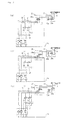
- FIG. 1 is a hydraulic circuit diagram of a reach stacker showing an embodiment of a hydraulic control device for an industrial machine.
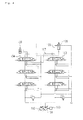
- FIGS. 2 (a) to 2 (c) are hydraulic circuit diagrams showing different operating states.
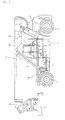
- FIG. 3 is a side view of the reach stacker.
- a reach stacker comprises a telescopic boom 6 supported on a frame 4 via a tower 5 so as to be raisable and lowerable, the frame 4 having a pair of front wheels 1 and rear wheels 2 and being cable of running by the action of an engine (power plant) 3.
- a spreader 7, which can hold a long container or the like, is suspended from the front end of an inner boom 6a of the telescopic boom 6.
- the telescopic boom 6 makes rising and lowering motions by the action of two tilt cylinders (hydraulically driven working machines) 8 provided as a pair between the frame 4 and an outer boom 6b, and also makes expanding and contracting motions by the action of a single telescopic cylinder (hydraulically driven working machine) 9 provided between the inner boom 6a and the outer boom 6b.
- a cab 11 is provided on the frame 4 so as to be slidable in a longitudinal direction via a pair of (i.e., right and left) rails 10.
- the two tilt cylinders 8 (only one of them is shown for convenience's sake in the drawing) are connected, via a main hydraulic (cylinder drive) circuit 21, to a first hydraulic pump 20 of a variable capacity type driven by the engine 3. These tilt cylinders 8 make expanding and contracting motions when a pressure oil from the first hydraulic pump 20 is supplied and discharged by a raising and lowering control valve (device) 22 interposed in the main hydraulic circuit 21.
- the single telescopic cylinder 9 is connected, via a main hydraulic (cylinder drive) circuit 24, to a second hydraulic pump 23 of a variable capacity type similarly driven by the engine 3.
- the single telescopic cylinder 9 makes expanding and contracting motions when a pressure oil from the second hydraulic pump 23 is supplied and discharged by an expansion and contraction control valve (device) 25 interposed in the main hydraulic circuit 24.
- the raising and lowering control valve (device) 22 includes a servo valve 26a for controlling the flow rate and direction of the pressure oil supplied to the tilt cylinder 8, a pressure compensating valve 27a, provided in a passage ahead of the servo valve 26a, for maintaining a constant flow rate under varying pressure (load), and a pressure control valve 28a provided in a passage leading to a tank 29.
- the expansion and contraction control valve (device) 25 includes a servo valve 26b for controlling the flow rate and direction of the pressure oil supplied to the telescopic cylinder 9, a pressure compensating valve 27b, provided in a passage ahead of the servo valve 26b, for maintaining a constant flow rate under varying pressure (load), and a pressure control valve 28b provided in a passage leading to the tank 29.
- Control over the swash plate inclination angles of the first hydraulic pump 20 and the second hydraulic pump 23 is load-responsive.
- the hydraulic pumps 20, 23 and the servo valves 26a, 26b corresponding to the hydraulic pumps 20, 23, respectively, are connected together by load pressure circuits 30, 31.
- the reference numerals 32, 33 denote check valves.
- a merging block 34 constituting a merging circuit which merges the pressure oils of the main hydraulic circuits 21, 24 on the two lines, and the load pressures of the load pressure circuits 30, 31 on the two lines, according to the operating conditions of the tilt cylinders 8 and the telescopic cylinder 9. That is, a merger/independence electromagnetic selector valve 35 is provided on a passage connecting the main hydraulic circuits 21, 24 on the two lines, while a merger/independence electromagnetic selector valve 36 is provided on a passage connecting the load pressure circuits 30, 31 on the two lines.
- differential circuit blocks 37, 38 are provided for refluxing the pressure oils from discharge (rod-side) ports during expansion of the tilt cylinder 8 and the telescopic cylinder 9 to supply (head-side) ports during expansion of these cylinders. That is, electromagnetic selector valves 39a, 39b, which can be opened during a predetermined expansion, are provided on bypass passages connecting head-side passages 21a, 24a and rod-side passages 21b, 24b of the main hydraulic circuits 21, 24. Moreover, electromagnetic selector valves 40a, 40b, which can be closed during a predetermined expansion, are provided on the rod-side passages 21b, 24b on the side of the control valves 22, 25 relative to the branch points of the bypass passages.
- the servo valves 26a, 26, the merger/independence electromagnetic selector valves 35, 36, and the electromagnetic selector valves 39a, 39b, 40a, 40b are driven and controlled by a working machine controller (ECU) (not shown).
- ECU working machine controller
- the working machine controller receives inlet signals from a joystick (not shown) operated by an operator inside the cab 11, and oil pressure sensors (not shown) incorporated in the tilt cylinder 8 and the telescopic cylinder 9.
- the working machine controller controls the merging block 34 so as to simultaneously merge the pressure oils of the main hydraulic circuits 21, 24 on the two lines, and the load pressures of the load pressure circuits 30, 31 on the two lines, for example, during a combined operation of the tilt cylinder 8 and the telescopic cylinder 9 under unloaded conditions of the reach stacker (when the spreader 7 does not hold a long container or the like), and controls the differential circuit 37 or 38 so as to reflux the pressure oil on the rod side to the head side during the expansion of the tilt cylinder 8 or the telescopic cylinder 9 which requires a high flow rate of pressure oil, thereby making it possible to achieve a no-load high speed action of the reach stacker.
- the working machine controller controls the merging block 34 so as to keep the pressure oils of the main hydraulic circuits 21, 24 and the load pressures of the load pressure circuits 30, 31 as individual two lines, without merging these pressure oils and these load pressures, during a combined operation of the tilt cylinder 8 and the telescopic cylinder 9 under loaded conditions of the reach stacker (when the spreader 7 holds a long container or the like), thereby making it possible to achieve a load-responsive action of the reach stacker under loaded conditions.
- FIGS. 2(a) to 2(c) A concrete description will be offered based on FIGS. 2(a) to 2(c).
- the servo valve 26a of the raising and lowering control valve 22 is switched to the right-hand position in the drawing, and the merger/independence electromagnetic selector valves 35, 36 of the merging block 34 are both closed.
- the electromagnetic selector valve 39a is closed, while the electromagnetic selector valve 40a is opened.
- the pressure oil of the first hydraulic pump 20 passes through the main hydraulic circuit 21, and supplied at a predetermined flow rate to the rod side of the tilt cylinder 8 by the servo valve 26a, without being merged with the pressure oil of the second hydraulic pump 23.
- the first hydraulic pump 20 varies in the amount of discharge in response to the load pressure of the load pressure circuit 30, exercising efficient control.
- the differential circuit block 37 does not function.
- the servo valve 26a of the raising and lowering control valve 22 is switched to the left-hand position in the drawing, and the merger/independence electromagnetic selector valves 35, 36 of the merging block 34 are both closed.
- the electromagnetic selector valve 39a is closed, while the electromagnetic selector valve 40a is opened.
- the pressure oil of the first hydraulic pump 20 passes through the main hydraulic circuit 21, and supplied at a predetermined flow rate to the head side of the tilt cylinder 8 by the servo valve 26a, without being merged with the pressure oil of the second hydraulic pump 23.
- the first hydraulic pump 20 varies in the amount of discharge in response to the load pressure of the load pressure circuit 30, exercising efficient control.
- the differential circuit block 37 does not function.
- the servo valve 26a of the raising and lowering control valve 22 is switched to the left-hand position in the drawing, and the merger/independence electromagnetic selector valves 35, 36 of the merging block 34 are both opened.
- the electromagnetic selector valve 39a is opened, while the electromagnetic selector valve 40a is closed.
- the pressure oil of the second hydraulic pump 23 is merged with the pressure oil of the first hydraulic pump 20 via the merger/independence electromagnetic selector valve 35, and a required high flow rate of pressure oil is supplied to the head side of the tilt cylinder 8 by the servo valve 26a. That is, at the initial stage of vertical ascent of the telescopic boom 6, the load is higher on the tilt cylinder 8 than on the telescopic cylinder 9, thus requiring a high flow rate of pressure oil.
- the adequate flow rate for this requirement can be supplied by causing the first hydraulic pump 20 and the second hydraulic pump 23 to function as if they were a single pump.
- the differential block 37 also functions to reflux the pressure oil on the rod side of the tilt cylinder 8 to the head side of the tilt cylinder 8 via the electromagnetic selector valve 39a without returning it to the tank 29.
- the flow rate of the pressure oil supplied to the head side of the tilt cylinder 8 is increased, thereby achieving an even higher speed action.
- the same load pressure is exerted on the first hydraulic pump 20 and the second hydraulic pump 23 via the merger/independence electromagnetic selector valve 36, and the amount of discharge become variable according to this load pressure.
- efficient control is effected.
- the hydraulic control device for an industrial machine can be applied not only to a heavy duty cargo-handling vehicle such as a reach stacker, but also to an industrial (transport) machine such as a crane.
Landscapes
- Engineering & Computer Science (AREA)
- Structural Engineering (AREA)
- General Engineering & Computer Science (AREA)
- Civil Engineering (AREA)
- Mechanical Engineering (AREA)
- Fluid Mechanics (AREA)
- Physics & Mathematics (AREA)
- Mining & Mineral Resources (AREA)
- Transportation (AREA)
- Geology (AREA)
- Life Sciences & Earth Sciences (AREA)
- Chemical & Material Sciences (AREA)
- Combustion & Propulsion (AREA)
- Fluid-Pressure Circuits (AREA)
- Forklifts And Lifting Vehicles (AREA)
Abstract
A hydraulic control device for an industrial machine, which can efficiently control a high flow rate of a pressure oil by a simple hydraulic instrument configuration, is provided. For this purpose, in a hydraulic control device for a reach stacker, including first and second hydraulic pumps (20, 23) of a variable capacity type driven by an engine (3) of the reach stacker, main hydraulic circuits (21, 24 on two lines connecting these hydraulic pumps to a tilt cylinder (8) and a telescopic cylinder (9) corresponding to the hydraulic pumps, and a raising and lowering control valve (22) and an expansion and contraction control valve (25), interposed in the main hydraulic circuits on the two lines, for controlling the flow rates and directions of pressure oils supplied to the tilt cylinder (8) and the telescopic cylinder (9), a merging block (34), which constitutes a merging circuit for merging the pressure oils of the main hydraulic circuits (21, 24) on the two lines according to operating conditions of the tilt cylinder (8) and the telescopic cylinder (9), is provided on the main hydraulic circuits located upstream of the control valves (22, 25).
Description
- This invention relates to a hydraulic control device for an industrial machine, and relates to a hydraulic control device preferred for use in a heavy duty cargo handling vehicle, such as a reach stacker, which has a plurality of main hydraulically driven working machines.
- A reach stacker having a spreader suspended from the front end of a telescopic boom has two main hydraulically driven working machines, i.e., a telescopic cylinder for expanding and contracting the telescopic boom, and a tilt cylinder for raising and lowering the telescopic boom. Hydraulic circuits therefor are also composed of two lines, i.e., a line for expansion and contraction, and a line for raising and lowering, and require high flow rates of pressure oil according to the working speed. This has posed the problem that during a vertically ascending operation of the spreader (under unloaded conditions of the reach stacker) or the like, there is need for a fixed pump capable of supplying a high flow rate of pressure oil to each line.
-
Patent Document 1 discloses, particularly, a technique of providing a merging valve for merging pressure oils from two hydraulic pumps in a hydraulic drive device for a working machine, such as a hydraulic shovel. - That is, as shown in FIG. 4, there are provided an
engine 100; a firsthydraulic pump 101 and a secondhydraulic pump 102, each of a variable capacity type, driven by theengine 100; a group of firstdirectional control valves 103 of a center bypass type connected to the firsthydraulic pump 101; a group of second directional control valves of a center bypass type connected to the secondhydraulic pump 102 and including a mergingdirectional control valve 104; amerging valve 106, connected to the farthest downstream directional control valve of the group of firstdirectional control valves 103 via acenter bypass passage 105, for merging the pressure oil of the firsthydraulic pump 101 with the pressure oil of the secondhydraulic pump 102 to enable the merged pressure oil to be supplied to the mergingdirectional control valve 104 of the group of second directional control valves; a mergingcircuit 107 for bringing themerging valve 106 and a supply port of the mergingdirectional control valve 104 into communication; and a mergingactuator 108 controlled by the mergingdirectional control valve 104. - According to the above-described configuration, when the merging
actuator 108 is to be driven, the mergingdirectional control valve 104 is switched to a right-hand position in FIG. 4 by a pilot pressure, and the mergingvalve 106 is switched to a closed position against a spring force. As a result, a hydraulic circuit between thecenter bypass passage 105 and the tank side is shut off. Thus, the pressure oil of the firsthydraulic pump 101 is supplied to the supply port of the mergingdirectional control valve 104 via thecenter bypass passage 105 and the mergingcircuit 107 upon merger with the pressure oil of the secondhydraulic pump 102. The pressure oil, as the product of merger between the pressure oils from the firsthydraulic pump 101 and the secondhydraulic pump 102, is supplied from the mergingdirectional control valve 104 to the mergingactuator 108. The mergingactuator 108 is thus activated to drive a crusher (as an attachment) of a hydraulic shovel (not shown), performing crushing work, etc. for rocks.
Patent Document 1: Japanese Patent Application Laid-Open No. 2001-295803 (FIG. 5) - With the hydraulic drive device of
Patent Document 1, however, when, for a combined operation of the crusher and an arm and a boom (not shown), the concerned directional control valve included in the group of firstdirectional control valves 103 is also switched, for example, the pressure oil of the firsthydraulic pump 101 is supplied to the concerneddirectional control valve 103, and thecenter bypass passage 105 is shut off by the concerneddirectional control valve 103 on the hydraulic circuit. Thus, the pressure oil of the firsthydraulic pump 101 is not supplied to themerging circuit 107. In other words, it is not that the pressure oil of the firsthydraulic pump 101 is merged with the pressure oil of the secondhydraulic pump 102 and supplied to the mergingactuator 108. - In the case of the above-described combined operation,
Patent Document 1 discloses as follows: In the actual operation, there are few cases where the concerneddirectional control valve 103 completely closes thecenter bypass passage 105. Thus, a part of the pressure oil of the firsthydraulic pump 101 tends to be supplied to themerging circuit 107. As a result, the mergingactuator 108 is prone to be driven by the part of the pressure oil of the firsthydraulic pump 101 and the pressure oil of the secondhydraulic pump 102. - With the above-mentioned combined operation, however, the
center bypass passage 105 for the concerneddirectional control valve 103 is necessarily constricted, so that the flow rate of the pressure oil supplied from the firsthydraulic pump 101 is itself limited. This has resulted in the drawback that a requirement of the mergingactuator 108 for a high flow rate of the pressure oil (in other words, a high speed action) cannot be fully satisfied. - It is therefore an object of the present invention to provide a hydraulic control device for an industrial machine, the hydraulic control device being capable of efficiently controlling a high flow rate of a pressure oil by a simple configuration of a hydraulic instrument.
- A hydraulic control device for an industrial machine according to the present invention, intended for attaining the above object, is a hydraulic control device for an industrial machine, including
a plurality of variable capacity hydraulic pumps driven by a power plant,
main hydraulic circuits on a plurality of lines connecting the hydraulic pumps to a plurality of hydraulically driven working machines, and
control valves, interposed in the main hydraulic circuits on the plurality of lines, for controlling flow rates and directions of pressure oils supplied to the hydraulically driven working machines, and characterized in that
a merging block, which constitutes a merging circuit for merging the pressure oils of the main hydraulic circuits on the plurality of lines according to operating conditions of the hydraulically driven working machines, is provided on the main hydraulic circuits located upstream of the control valves. - Preferably, differential circuit blocks, which reflux the pressure oils from discharge (rod-side) ports of the hydraulically driven working machines to supply (head-side) ports of the hydraulically driven working machines, are provided on the main hydraulic (cylinder drive) circuits between the control valves and the hydraulically driven working machines corresponding to the control valves, thereby refluxing the pressure oils during the merging of the pressure oils.
- Preferably, control over swash plate inclination angles of the hydraulic pumps is load-responsive, and the hydraulic pumps and the control valves corresponding to the hydraulic pumps are connected together by load pressure (load sensing pressure) circuits.
- It is preferredbecause of system efficiency that the hydraulically driven working machines are a tilt cylinder and a telescopic cylinder for a telescopic boom of a reach stacker, and the pressure oils of the main hydraulic circuits on the plurality of lines, and load pressures of load pressure circuits are simultaneously merged by the merging block during a combined operation of both cylinders.
- According to the present invention with the above features, during a combined operation or the like of the hydraulically driven working machine under unloaded conditions at a lower load pressure than that under loaded conditions of the machine, the pressure oils of the main hydraulic circuits on the plurality of lines are merged, and the plurality of hydraulic pumps are used as if they were a single pump. By so doing, a high flow rate of pressure oil can be controlled efficiently to achieve a no-load high speed action. Furthermore, the present invention merely involves a configuration in which the merging block is provided in the main hydraulic circuits located upstream of the control valves. Hence, the desired function can be performed with the use of a simple hydraulic instrument configuration.
-
- [FIG.1] A hydraulic circuit diagram of a reach stacker showing an embodiment of a hydraulic control device for an industrial machine.
- [FIGS. 2(a) to 2 (c)] Hydraulic circuit diagrams showing different operating states.
- [FIG. 3] A side view of the reach stacker.
- [FIG. 4] A hydraulic circuit diagram showing a conventional example.
Description of the Reference Numerals: 1 front wheel, 2 rear wheel, 3 engine, 4 frame, 5 tower, 6 telescopic boom, 7 spreader, 8 tilt cylinder, 9 telescopic cylinder, 10 rail, 11 cab, 20 first hydraulic pump, 21 main hydraulic circuit, 22 raising and lowering control valve, 23 second hydraulic pump, 24 main hydraulic circuit, 25 expansion and contraction control valve, 26a, 26b servo valves, 27a, 27b pressure compensating valves, 28a, 28b pressure control valves, 29 tank, 30, 31 load pressure circuits, 32, 33 check valves, 34 merging block, 35, 36 merger/independence electromagnetic selector valves, 37, 38 differential circuit blocks, 39a, 39b electromagnetic selector valves, 40a, 40b electromagnetic selector valves. - A hydraulic control device for an industrial machine according to the present invention will now be described in detail by an embodiment with reference to the accompanying drawings.
- FIG. 1 is a hydraulic circuit diagram of a reach stacker showing an embodiment of a hydraulic control device for an industrial machine. FIGS. 2 (a) to 2 (c) are hydraulic circuit diagrams showing different operating states. FIG. 3 is a side view of the reach stacker.
- As shown in FIG. 3, a reach stacker comprises a telescopic boom 6 supported on a frame 4 via a
tower 5 so as to be raisable and lowerable, the frame 4 having a pair offront wheels 1 andrear wheels 2 and being cable of running by the action of an engine (power plant) 3. Aspreader 7, which can hold a long container or the like, is suspended from the front end of an inner boom 6a of the telescopic boom 6. - The telescopic boom 6 makes rising and lowering motions by the action of two tilt cylinders (hydraulically driven working machines) 8 provided as a pair between the frame 4 and an outer boom 6b, and also makes expanding and contracting motions by the action of a single telescopic cylinder (hydraulically driven working machine) 9 provided between the inner boom 6a and the outer boom 6b. A
cab 11 is provided on the frame 4 so as to be slidable in a longitudinal direction via a pair of (i.e., right and left)rails 10. - As shown in FIG. 1, the two tilt cylinders 8 (only one of them is shown for convenience's sake in the drawing) are connected, via a main hydraulic (cylinder drive)
circuit 21, to a firsthydraulic pump 20 of a variable capacity type driven by theengine 3. Thesetilt cylinders 8 make expanding and contracting motions when a pressure oil from the firsthydraulic pump 20 is supplied and discharged by a raising and lowering control valve (device) 22 interposed in the mainhydraulic circuit 21. The singletelescopic cylinder 9 is connected, via a main hydraulic (cylinder drive)circuit 24, to a secondhydraulic pump 23 of a variable capacity type similarly driven by theengine 3. The singletelescopic cylinder 9 makes expanding and contracting motions when a pressure oil from the secondhydraulic pump 23 is supplied and discharged by an expansion and contraction control valve (device) 25 interposed in the mainhydraulic circuit 24. - The raising and lowering control valve (device) 22 includes a
servo valve 26a for controlling the flow rate and direction of the pressure oil supplied to thetilt cylinder 8, apressure compensating valve 27a, provided in a passage ahead of theservo valve 26a, for maintaining a constant flow rate under varying pressure (load), and apressure control valve 28a provided in a passage leading to atank 29. The expansion and contraction control valve (device) 25 includes aservo valve 26b for controlling the flow rate and direction of the pressure oil supplied to thetelescopic cylinder 9, apressure compensating valve 27b, provided in a passage ahead of theservo valve 26b, for maintaining a constant flow rate under varying pressure (load), and apressure control valve 28b provided in a passage leading to thetank 29. - Control over the swash plate inclination angles of the first
hydraulic pump 20 and the secondhydraulic pump 23 is load-responsive. Thehydraulic pumps servo valves hydraulic pumps load pressure circuits reference numerals - In the main
hydraulic circuits load pressure circuits control valves block 34 constituting a merging circuit which merges the pressure oils of the mainhydraulic circuits load pressure circuits tilt cylinders 8 and thetelescopic cylinder 9. That is, a merger/independenceelectromagnetic selector valve 35 is provided on a passage connecting the mainhydraulic circuits electromagnetic selector valve 36 is provided on a passage connecting theload pressure circuits - On the main
hydraulic circuits control valves tilt cylinder 8 and thetelescopic cylinder 9, differential circuit blocks 37, 38 are provided for refluxing the pressure oils from discharge (rod-side) ports during expansion of thetilt cylinder 8 and thetelescopic cylinder 9 to supply (head-side) ports during expansion of these cylinders. That is,electromagnetic selector valves side passages side passages hydraulic circuits electromagnetic selector valves side passages control valves - The
servo valves 26a, 26, the merger/independenceelectromagnetic selector valves electromagnetic selector valves - The working machine controller receives inlet signals from a joystick (not shown) operated by an operator inside the
cab 11, and oil pressure sensors (not shown) incorporated in thetilt cylinder 8 and thetelescopic cylinder 9. In response to the inlet signals, the working machine controller controls the mergingblock 34 so as to simultaneously merge the pressure oils of the mainhydraulic circuits load pressure circuits tilt cylinder 8 and thetelescopic cylinder 9 under unloaded conditions of the reach stacker (when thespreader 7 does not hold a long container or the like), and controls thedifferential circuit tilt cylinder 8 or thetelescopic cylinder 9 which requires a high flow rate of pressure oil, thereby making it possible to achieve a no-load high speed action of the reach stacker. - On the other hand, the working machine controller controls the merging
block 34 so as to keep the pressure oils of the mainhydraulic circuits load pressure circuits tilt cylinder 8 and thetelescopic cylinder 9 under loaded conditions of the reach stacker (when thespreader 7 holds a long container or the like), thereby making it possible to achieve a load-responsive action of the reach stacker under loaded conditions. - A concrete description will be offered based on FIGS. 2(a) to 2(c). During contraction (individual operation) of the
tilt cylinder 8 regardless of the loaded condition of the reach stacker, as shown in FIG. 2 (a), theservo valve 26a of the raising and loweringcontrol valve 22 is switched to the right-hand position in the drawing, and the merger/independenceelectromagnetic selector valves block 34 are both closed. In thedifferential circuit block 37, theelectromagnetic selector valve 39a is closed, while theelectromagnetic selector valve 40a is opened. - As a result, the pressure oil of the first
hydraulic pump 20 passes through the mainhydraulic circuit 21, and supplied at a predetermined flow rate to the rod side of thetilt cylinder 8 by theservo valve 26a, without being merged with the pressure oil of the secondhydraulic pump 23. On this occasion, the firsthydraulic pump 20 varies in the amount of discharge in response to the load pressure of theload pressure circuit 30, exercising efficient control. Thedifferential circuit block 37 does not function. - During expansion (individual operation) of the
tilt cylinder 8 under the loaded conditions of the reach stacker, as shown in FIG. 2(b), theservo valve 26a of the raising and loweringcontrol valve 22 is switched to the left-hand position in the drawing, and the merger/independenceelectromagnetic selector valves block 34 are both closed. In thedifferential circuit block 37, theelectromagnetic selector valve 39a is closed, while theelectromagnetic selector valve 40a is opened. - As a result, the pressure oil of the first
hydraulic pump 20 passes through the mainhydraulic circuit 21, and supplied at a predetermined flow rate to the head side of thetilt cylinder 8 by theservo valve 26a, without being merged with the pressure oil of the secondhydraulic pump 23. On this occasion, the firsthydraulic pump 20 varies in the amount of discharge in response to the load pressure of theload pressure circuit 30, exercising efficient control. Thedifferential circuit block 37 does not function. - Next, during expansion of the
tilt cylinder 8 under unloaded conditions at a lower load pressure than that under loaded conditions of the reach stacker (i.e., during a combined operation of thetilt cylinder 8 in combination with thetelescopic cylinder 9 when the telescopic boom 6 vertically ascends), as shown in FIG. 2 (c), theservo valve 26a of the raising and loweringcontrol valve 22 is switched to the left-hand position in the drawing, and the merger/independenceelectromagnetic selector valves block 34 are both opened. In thedifferential circuit block 37, theelectromagnetic selector valve 39a is opened, while theelectromagnetic selector valve 40a is closed. - As a result, the pressure oil of the second
hydraulic pump 23 is merged with the pressure oil of the firsthydraulic pump 20 via the merger/independenceelectromagnetic selector valve 35, and a required high flow rate of pressure oil is supplied to the head side of thetilt cylinder 8 by theservo valve 26a. That is, at the initial stage of vertical ascent of the telescopic boom 6, the load is higher on thetilt cylinder 8 than on thetelescopic cylinder 9, thus requiring a high flow rate of pressure oil. The adequate flow rate for this requirement can be supplied by causing the firsthydraulic pump 20 and the secondhydraulic pump 23 to function as if they were a single pump. - During the above action, the
differential block 37 also functions to reflux the pressure oil on the rod side of thetilt cylinder 8 to the head side of thetilt cylinder 8 via theelectromagnetic selector valve 39a without returning it to thetank 29. Thus, the flow rate of the pressure oil supplied to the head side of thetilt cylinder 8 is increased, thereby achieving an even higher speed action. On this occasion, the same load pressure is exerted on the firsthydraulic pump 20 and the secondhydraulic pump 23 via the merger/independenceelectromagnetic selector valve 36, and the amount of discharge become variable according to this load pressure. Thus, efficient control is effected. - Explanations for the actions for the
telescopic cylinder 9 are omitted, because it is self-evident that the same actions as those for thetilt cylinder 8 are performed for thetelescopic cylinder 9. In the above-described embodiment, the differential circuit blocks 37, 38 may be omitted, and the first and secondhydraulic pumps load pressure circuits - The hydraulic control device for an industrial machine according to the present invention can be applied not only to a heavy duty cargo-handling vehicle such as a reach stacker, but also to an industrial (transport) machine such as a crane.
Claims (4)
- A hydraulic control device for an industrial machine, including
a plurality of variable capacity hydraulic pumps driven by a power plant,
main hydraulic circuits on a plurality of lines connecting said hydraulic pumps to a plurality of hydraulically driven working machines, and
control valves, interposed in said main hydraulic circuits on the plurality of lines, for controlling flow rates and directions of pressure oils supplied to said hydraulically driven working machines, and characterized in that
a merging block, which constitutes a merging circuit for merging the pressure oils of said main hydraulic circuits on the plurality of lines according to operating conditions of said hydraulically driven working machines, is provided on said main hydraulic circuits located upstream of said control valves. - The hydraulic control device for an industrial machine according to claim 1, characterized in that differential circuit blocks, which reflux the pressure oils from discharge ports of said hydraulically driven working machines to supply ports of said hydraulically driven working machines, are provided on said main hydraulic circuits between said control valves and said hydraulically driven working machines corresponding to said control valves, thereby refluxing said pressure oils during said merging of the pressure oils.
- The hydraulic control device for an industrial machine according to claim 1 or 2, characterized in that control over swash plate inclination angles of said hydraulic pumps is load-responsive, and said hydraulic pumps and said control valves corresponding to said hydraulic pumps are connected together by load pressure circuits.
- The hydraulic control device for an industrial machine according to claim 1, 2 or 3, characterized in that said hydraulically driven working machines are a tilt cylinder and a telescopic cylinder for a telescopic boom of a reach stacker, and the pressure oils of said main hydraulic circuits on the plurality of lines, and load pressures of load pressure circuits are simultaneously merged by said merging block during a combined operation of said cylinders.
Applications Claiming Priority (2)
| Application Number | Priority Date | Filing Date | Title |
|---|---|---|---|
| JP2003335194A JP2005098455A (en) | 2003-09-26 | 2003-09-26 | Hydraulic controller of industrial machinery |
| PCT/JP2004/013611 WO2005031172A1 (en) | 2003-09-26 | 2004-09-17 | Hydraulic control device of industrial machinery |
Publications (1)
| Publication Number | Publication Date |
|---|---|
| EP1666735A1 true EP1666735A1 (en) | 2006-06-07 |
Family
ID=34386053
Family Applications (1)
| Application Number | Title | Priority Date | Filing Date |
|---|---|---|---|
| EP04773255A Withdrawn EP1666735A1 (en) | 2003-09-26 | 2004-09-17 | Hydraulic control device of industrial machinery |
Country Status (6)
| Country | Link |
|---|---|
| US (1) | US20060277905A1 (en) |
| EP (1) | EP1666735A1 (en) |
| JP (1) | JP2005098455A (en) |
| CN (1) | CN1846068A (en) |
| AU (1) | AU2004276616A1 (en) |
| WO (1) | WO2005031172A1 (en) |
Cited By (4)
| Publication number | Priority date | Publication date | Assignee | Title |
|---|---|---|---|---|
| WO2008031483A1 (en) * | 2006-09-13 | 2008-03-20 | Robert Bosch Gmbh | Hydraulic control arrangement for the demand-current-regulated (load-sensing-regulated) pressure medium supply to a plurality of hydraulic consumers |
| EP2876075A3 (en) * | 2013-11-26 | 2015-07-22 | Tadano, Ltd. | Boom extending and retracting apparatus of a crane |
| DE112016000101B4 (en) | 2016-08-26 | 2019-05-02 | Komatsu Ltd. | CONTROL SYSTEM, WORK MACHINE AND CONTROL PROCEDURE |
| DE112016000103B4 (en) | 2016-07-29 | 2019-08-14 | Komatsu Ltd. | Control system, work machine and control method |
Families Citing this family (32)
| Publication number | Priority date | Publication date | Assignee | Title |
|---|---|---|---|---|
| DE102004020371A1 (en) * | 2004-04-23 | 2005-11-10 | Botschafter-Knopff, Ilse | Hydraulic control device |
| JP4859407B2 (en) * | 2005-07-19 | 2012-01-25 | Tcm株式会社 | Horizontal holding device for cargo of cargo handling vehicle |
| CA2623109C (en) | 2005-10-14 | 2019-02-19 | Innate Pharma | Nk cell-depleting antibodies for treating immunoproliferative disorders |
| DE102005059238B4 (en) * | 2005-12-12 | 2016-03-31 | Linde Hydraulics Gmbh & Co. Kg | Control valve device for controlling a consumer |
| JP4937663B2 (en) * | 2006-07-31 | 2012-05-23 | キャタピラー エス エー アール エル | Oil level control method for work machines |
| DE102007062888A1 (en) * | 2007-12-28 | 2009-07-02 | Robert Bosch Gmbh | Method for controlling a hydrostatic drive |
| JP2011046479A (en) * | 2009-08-27 | 2011-03-10 | Tcm Corp | Cargo handling device of reach stacker |
| CN101670984B (en) * | 2009-09-29 | 2012-06-06 | 长沙中联重工科技发展股份有限公司 | Optimal control method and control system of single-cylinder bolt type telescopic boom trail |
| CN102695885B (en) * | 2009-12-02 | 2015-04-22 | 沃尔沃建筑设备公司 | A method for controlling a hydraulic system of a working machine |
| CN101718284B (en) * | 2009-12-09 | 2012-06-27 | 中国重型机械研究院有限公司 | Composite control hydraulic system for frame beam |
| KR101718835B1 (en) * | 2010-05-17 | 2017-03-23 | 볼보 컨스트럭션 이큅먼트 에이비 | Hydraulic control valve for construction machinery |
| JP5763317B2 (en) | 2010-09-14 | 2015-08-12 | ニチユ三菱フォークリフト株式会社 | Industrial vehicle |
| CN102423526B (en) * | 2011-09-14 | 2013-11-13 | 徐州重型机械有限公司 | High rise building and fixed fire fighting system thereof |
| CN102330649A (en) * | 2011-09-14 | 2012-01-25 | 徐州重型机械有限公司 | Plunger water pump and liquid control system thereof |
| CN102423521A (en) * | 2011-09-14 | 2012-04-25 | 徐州重型机械有限公司 | Fire extinguishing system and fire engine containing the same |
| CN102701119B (en) * | 2012-06-25 | 2014-04-16 | 安徽合力股份有限公司 | Forward-shift impact preventing hydraulic system for forward-shift type fork truck mast |
| CN103658077B (en) * | 2012-08-31 | 2016-04-27 | 鸿富锦精密工业(深圳)有限公司 | Surface cleaning apparatus |
| CN103287980B (en) * | 2013-06-27 | 2014-10-29 | 湖南中铁五新重工有限公司 | Cantilever crane vertical lift control system |
| CN103738889B (en) * | 2014-01-16 | 2016-02-10 | 安徽纳威光机电科技发展有限公司 | Integrated electric electro-hydraulic proportional control system |
| CN103821451B (en) * | 2014-02-28 | 2017-04-12 | 金川集团股份有限公司 | Hydraulic control system of anti-clamping drill rod of rock drilling machine |
| JP6156221B2 (en) * | 2014-03-26 | 2017-07-05 | 株式会社豊田自動織機 | Industrial vehicle |
| CN105443487B (en) * | 2015-03-04 | 2018-01-16 | 徐州重型机械有限公司 | The control system and method in hydraulic differential loop, crane and lathe |
| CN105271070B (en) * | 2015-08-07 | 2018-06-05 | 林德(中国)叉车有限公司 | A kind of truck hydraulic energy-saving control system and the method for reducing fork truck operating power consumption |
| US10267019B2 (en) * | 2015-11-20 | 2019-04-23 | Caterpillar Inc. | Divided pump implement valve and system |
| CN106006413A (en) * | 2016-08-08 | 2016-10-12 | 中联重科股份有限公司 | Hydraulic control circuit of telescopic boom and engineering machinery with hydraulic control circuit |
| CN106194867A (en) * | 2016-08-31 | 2016-12-07 | 湖南华强电气股份有限公司 | A kind of hydraulic system and mould |
| DE102018202148B3 (en) * | 2018-02-12 | 2019-03-07 | Hawe Hydraulik Se | Hydraulic valve assembly with forced switching and mobile hydraulic system |
| KR102090447B1 (en) * | 2018-07-31 | 2020-04-23 | (주)토탈소프트뱅크 | Reach stacker and method of container loading and unloading by using the same |
| GB201912665D0 (en) | 2019-09-03 | 2019-10-16 | Artemis Intelligent Power Ltd | Hydraulic apparatus |
| JP6859411B2 (en) * | 2019-09-26 | 2021-04-14 | 古河ユニック株式会社 | Speed-up valve device |
| CN110762071B (en) | 2019-11-01 | 2021-07-06 | 中国海洋石油集团有限公司 | Hydraulic power system for underground equipment and underground equipment |
| US11767860B2 (en) * | 2021-11-30 | 2023-09-26 | Cnh Industrial America Llc | Smart flow dual pump hydraulic system |
Family Cites Families (7)
| Publication number | Priority date | Publication date | Assignee | Title |
|---|---|---|---|---|
| DE3044144A1 (en) * | 1980-11-24 | 1982-09-09 | Linde Ag, 6200 Wiesbaden | HYDROSTATIC DRIVE SYSTEM WITH ONE ADJUSTABLE PUMP AND SEVERAL CONSUMERS |
| DE4100988C2 (en) * | 1991-01-15 | 2001-05-10 | Linde Ag | Hydraulic drive system |
| JPH06123302A (en) * | 1992-10-08 | 1994-05-06 | Kayaba Ind Co Ltd | Oil pressure controller of construction machine |
| JP2581858Y2 (en) * | 1992-10-27 | 1998-09-24 | 株式会社小松製作所 | Split / merge switching device for multiple pumps in load sensing system |
| JP3596967B2 (en) * | 1996-02-02 | 2004-12-02 | 日立建機株式会社 | Hydraulic drive for construction machinery |
| JP3446023B2 (en) * | 1997-03-24 | 2003-09-16 | 大淀小松株式会社 | Hydraulic equipment |
| JP2001304202A (en) * | 2000-04-21 | 2001-10-31 | Shin Caterpillar Mitsubishi Ltd | Fluid pressure circuit |
-
2003
- 2003-09-26 JP JP2003335194A patent/JP2005098455A/en not_active Withdrawn
-
2004
- 2004-09-17 AU AU2004276616A patent/AU2004276616A1/en not_active Abandoned
- 2004-09-17 CN CNA2004800250800A patent/CN1846068A/en active Pending
- 2004-09-17 US US10/570,490 patent/US20060277905A1/en not_active Abandoned
- 2004-09-17 WO PCT/JP2004/013611 patent/WO2005031172A1/en active Application Filing
- 2004-09-17 EP EP04773255A patent/EP1666735A1/en not_active Withdrawn
Non-Patent Citations (1)
| Title |
|---|
| See references of WO2005031172A1 * |
Cited By (8)
| Publication number | Priority date | Publication date | Assignee | Title |
|---|---|---|---|---|
| WO2008031483A1 (en) * | 2006-09-13 | 2008-03-20 | Robert Bosch Gmbh | Hydraulic control arrangement for the demand-current-regulated (load-sensing-regulated) pressure medium supply to a plurality of hydraulic consumers |
| EP2876075A3 (en) * | 2013-11-26 | 2015-07-22 | Tadano, Ltd. | Boom extending and retracting apparatus of a crane |
| US9783396B2 (en) | 2013-11-26 | 2017-10-10 | Tadano Ltd. | Boom extending and retracting apparatus of a crane |
| AU2014265140B2 (en) * | 2013-11-26 | 2019-01-31 | Tadano Ltd. | Boom extending and retracting apparatus of a crane |
| DE112016000103B4 (en) | 2016-07-29 | 2019-08-14 | Komatsu Ltd. | Control system, work machine and control method |
| US10385545B2 (en) | 2016-07-29 | 2019-08-20 | Komatsu Ltd. | Control system, work machine, and control method |
| DE112016000101B4 (en) | 2016-08-26 | 2019-05-02 | Komatsu Ltd. | CONTROL SYSTEM, WORK MACHINE AND CONTROL PROCEDURE |
| US10604913B2 (en) | 2016-08-26 | 2020-03-31 | Komatsu Ltd. | Control system, work machine, and control method |
Also Published As
| Publication number | Publication date |
|---|---|
| CN1846068A (en) | 2006-10-11 |
| US20060277905A1 (en) | 2006-12-14 |
| WO2005031172A1 (en) | 2005-04-07 |
| AU2004276616A1 (en) | 2005-04-07 |
| JP2005098455A (en) | 2005-04-14 |
Similar Documents
| Publication | Publication Date | Title |
|---|---|---|
| EP1666735A1 (en) | Hydraulic control device of industrial machinery | |
| US9080310B2 (en) | Closed-loop hydraulic system having regeneration configuration | |
| KR100665358B1 (en) | Mobile handling device | |
| EP0927794B1 (en) | Turning excavator comprising a hydraulic circuit | |
| KR101754290B1 (en) | Hydraulic drive system for construction machine | |
| US20170274930A1 (en) | System architectures for steering and work functions in a wheel | |
| EP2652212B1 (en) | Closed loop drive circuit with open circuit pump assist for high speed travel | |
| US9932993B2 (en) | System and method for hydraulic energy recovery | |
| KR102510852B1 (en) | Hydraulic system and hydraulic control method for construction machine | |
| EP3203087B1 (en) | Work vehicle hydraulic drive system | |
| KR102403991B1 (en) | Boom speed increase hydraulic system for construction machinery | |
| JP4410512B2 (en) | Hydraulic drive | |
| EP3505688B1 (en) | System for controlling construction machinery and method for controlling construction machinery | |
| CN103813940B (en) | Carrying vehicle | |
| EP2955389A1 (en) | Hydraulic system with energy recovery | |
| CN104220762B (en) | The hydraulic circuit of construction machinery and control device thereof | |
| WO2013048712A1 (en) | Regeneration configuration for closed-loop hydraulic systems | |
| CN107882789B (en) | Electro-hydraulic system with negative flow control | |
| WO2016169939A1 (en) | Hydraulic circuit and working machine | |
| EP2918733B1 (en) | Construction machine | |
| EP3683453B1 (en) | Driving device of construction equipment | |
| US4614475A (en) | Hydraulic circuit system for civil engineering and architectural machinery | |
| CN111810476B (en) | Construction machine and method for controlling a construction machine | |
| KR101474070B1 (en) | Hydraulic circuit of construction equipment | |
| US11098462B2 (en) | Construction machine |
Legal Events
| Date | Code | Title | Description |
|---|---|---|---|
| PUAI | Public reference made under article 153(3) epc to a published international application that has entered the european phase |
Free format text: ORIGINAL CODE: 0009012 |
|
| 17P | Request for examination filed |
Effective date: 20060223 |
|
| AK | Designated contracting states |
Kind code of ref document: A1 Designated state(s): DE IT SE |
|
| DAX | Request for extension of the european patent (deleted) | ||
| RBV | Designated contracting states (corrected) |
Designated state(s): DE IT SE |
|
| STAA | Information on the status of an ep patent application or granted ep patent |
Free format text: STATUS: THE APPLICATION HAS BEEN WITHDRAWN |
|
| 18W | Application withdrawn |
Effective date: 20090317 |