EP1666720A1 - Fuel injection valve for internal combustion engine - Google Patents
Fuel injection valve for internal combustion engine Download PDFInfo
- Publication number
- EP1666720A1 EP1666720A1 EP04772977A EP04772977A EP1666720A1 EP 1666720 A1 EP1666720 A1 EP 1666720A1 EP 04772977 A EP04772977 A EP 04772977A EP 04772977 A EP04772977 A EP 04772977A EP 1666720 A1 EP1666720 A1 EP 1666720A1
- Authority
- EP
- European Patent Office
- Prior art keywords
- nozzle
- fuel injection
- fuel
- guide hole
- injection valve
- Prior art date
- Legal status (The legal status is an assumption and is not a legal conclusion. Google has not performed a legal analysis and makes no representation as to the accuracy of the status listed.)
- Granted
Links
Images


Classifications
-
- F—MECHANICAL ENGINEERING; LIGHTING; HEATING; WEAPONS; BLASTING
- F02—COMBUSTION ENGINES; HOT-GAS OR COMBUSTION-PRODUCT ENGINE PLANTS
- F02M—SUPPLYING COMBUSTION ENGINES IN GENERAL WITH COMBUSTIBLE MIXTURES OR CONSTITUENTS THEREOF
- F02M61/00—Fuel-injectors not provided for in groups F02M39/00 - F02M57/00 or F02M67/00
- F02M61/04—Fuel-injectors not provided for in groups F02M39/00 - F02M57/00 or F02M67/00 having valves, e.g. having a plurality of valves in series
- F02M61/10—Other injectors with elongated valve bodies, i.e. of needle-valve type
- F02M61/12—Other injectors with elongated valve bodies, i.e. of needle-valve type characterised by the provision of guiding or centring means for valve bodies
-
- F—MECHANICAL ENGINEERING; LIGHTING; HEATING; WEAPONS; BLASTING
- F02—COMBUSTION ENGINES; HOT-GAS OR COMBUSTION-PRODUCT ENGINE PLANTS
- F02M—SUPPLYING COMBUSTION ENGINES IN GENERAL WITH COMBUSTIBLE MIXTURES OR CONSTITUENTS THEREOF
- F02M61/00—Fuel-injectors not provided for in groups F02M39/00 - F02M57/00 or F02M67/00
- F02M61/04—Fuel-injectors not provided for in groups F02M39/00 - F02M57/00 or F02M67/00 having valves, e.g. having a plurality of valves in series
- F02M61/10—Other injectors with elongated valve bodies, i.e. of needle-valve type
-
- F—MECHANICAL ENGINEERING; LIGHTING; HEATING; WEAPONS; BLASTING
- F02—COMBUSTION ENGINES; HOT-GAS OR COMBUSTION-PRODUCT ENGINE PLANTS
- F02M—SUPPLYING COMBUSTION ENGINES IN GENERAL WITH COMBUSTIBLE MIXTURES OR CONSTITUENTS THEREOF
- F02M55/00—Fuel-injection apparatus characterised by their fuel conduits or their venting means; Arrangements of conduits between fuel tank and pump F02M37/00
- F02M55/002—Arrangement of leakage or drain conduits in or from injectors
-
- F—MECHANICAL ENGINEERING; LIGHTING; HEATING; WEAPONS; BLASTING
- F02—COMBUSTION ENGINES; HOT-GAS OR COMBUSTION-PRODUCT ENGINE PLANTS
- F02M—SUPPLYING COMBUSTION ENGINES IN GENERAL WITH COMBUSTIBLE MIXTURES OR CONSTITUENTS THEREOF
- F02M61/00—Fuel-injectors not provided for in groups F02M39/00 - F02M57/00 or F02M67/00
- F02M61/16—Details not provided for in, or of interest apart from, the apparatus of groups F02M61/02 - F02M61/14
-
- F—MECHANICAL ENGINEERING; LIGHTING; HEATING; WEAPONS; BLASTING
- F02—COMBUSTION ENGINES; HOT-GAS OR COMBUSTION-PRODUCT ENGINE PLANTS
- F02M—SUPPLYING COMBUSTION ENGINES IN GENERAL WITH COMBUSTIBLE MIXTURES OR CONSTITUENTS THEREOF
- F02M2200/00—Details of fuel-injection apparatus, not otherwise provided for
- F02M2200/07—Fuel-injection apparatus having means for avoiding sticking of valve or armature, e.g. preventing hydraulic or magnetic sticking of parts
Definitions
- a fuel injection valve for directly injecting/supplying fuel to the inside of a cylinder of an internal combustion engine such as in the Common Rail System
- a fuel injection valve of the type disclosed in JP-A-7-310621, for example is known.
- This fuel injection valve is configured such that an electromagnetic valve is powered and opened so that a control chamber inside the body of the fuel injection valve becomes communicated with a low-pressure portion, whereby the back pressure of a valve piston is removed, a nozzle needle is lifted, fuel injection is initiated, the powering of the electromagnetic valve is stopped after the elapse of a predetermined amount of time, and the communicated state between the control chamber and the low-pressure portion is released, whereby predetermined back pressure acts on the valve piston, the nozzle needle is pushed down, and fuel injection is terminated.
- An oil pool 37 that stores the high-pressure fuel introduced thereto from the passage 26 via a passage 36 is formed inside the nozzle body 31.
- a tapered portion 38 for causing force to act in a direction where the nozzle needle 32 is moved away from the injection hole 35 due to the pressure of the high-pressure fuel inside the oil pool 37 is formed on the nozzle needle 32.
- tapered form of the tapered portions 33B and 33E in FIG. 2 and FIG. 3 are not limited to being linear and can also be optional tapered forms, such as curvilinear or a mixture of linear and curvilinear.
Landscapes
- Engineering & Computer Science (AREA)
- Chemical & Material Sciences (AREA)
- Combustion & Propulsion (AREA)
- Mechanical Engineering (AREA)
- General Engineering & Computer Science (AREA)
- Fuel-Injection Apparatus (AREA)
Abstract
Description
- The present invention relates to a fuel injection valve for directly injecting/supplying fuel to the inside of a cylinder of an internal combustion engine.
- As a fuel injection valve for directly injecting/supplying fuel to the inside of a cylinder of an internal combustion engine such as in the Common Rail System, a fuel injection valve of the type disclosed in JP-A-7-310621, for example, is known. This fuel injection valve is configured such that an electromagnetic valve is powered and opened so that a control chamber inside the body of the fuel injection valve becomes communicated with a low-pressure portion, whereby the back pressure of a valve piston is removed, a nozzle needle is lifted, fuel injection is initiated, the powering of the electromagnetic valve is stopped after the elapse of a predetermined amount of time, and the communicated state between the control chamber and the low-pressure portion is released, whereby predetermined back pressure acts on the valve piston, the nozzle needle is pushed down, and fuel injection is terminated.
- Incidentally, in regions of extremely low temperature, wax is mixed into the fuel in order to ensure that the aforementioned smooth operation of the fuel injection valve can be secured even at a low temperature. Consequently, there is the problem that, depending on the running condition of the engine, as when the engine is started in a low temperature atmosphere such as -20°C or below, the wax mixed into the fuel is deposited in portions of the fuel injection valve and causes various problems. Particularly when the wax is deposited in a fuel leak passage for allowing the fuel to escape from the high-pressure side to the low-pressure side, there is a tendency for the fuel to become unable to pass therethrough, and for the operation of the fuel injection valve, and particularly the operation of the nozzle needle, to become unstable. As a result, there is the problem that this triggers drawbacks such as the fuel injection operation of the fuel injection valve becoming unstable.
- It is an object of the present invention to provide a fuel injection valve for an internal combustion engine that can solve the aforementioned problem in the prior art.
- It is another object of the present invention to provide a fuel injection valve for an internal combustion engine that can speedily discharge solidified matter when solidified matter arises in the fuel.
- In the present invention, a nozzle needle and/or its guide hole are/is tapered in a fuel injection valve for an internal combustion engine, so when a component included in the fuel solidifies, the solidified matter is speedily discharged from a gap serving as a fuel leak passage formed between the nozzle needle and the guide hole.
- According to the present invention, there is proposed a fuel injection valve for an internal combustion engine comprising a nozzle fixed to a leading end portion of a nozzle holder, with the nozzle being configured such that a nozzle needle inserted into a guide hole inside a nozzle body is guided by the guide hole and moves in an axial direction to open/close an injection hole, wherein at least part of a gap formed between the nozzle needle and the guide hole has a tapered shape that widens toward the nozzle holder. The angle of the tapered portion can be appropriately determined.
- The nozzle needle is supported and guided in the guide hole such that the nozzle needle is movable in an axial direction inside the guide hole. The gap between the nozzle needle and the guide hole is extremely narrow, and high-pressure fuel of a high-pressure portion of the leading end of the nozzle needle slightly leaks through the gap to a low-pressure portion at the nozzle holder side. At least part of the gap is tapered, and the gap has a form including a portion that widens like a skirt from the high-pressure portion to the fuel low-pressure portion. As a result, the width of the gap becomes larger closer to the low-pressure portion. Consequently, when mixed matter such as wax included in the leak fuel solidifies and is deposited inside the gap when the engine is running at a low temperature, the solidified matter inside the gap is sent to the low-pressure side by the movement of the piston of the nozzle needle, so that the solidified matter does not remain inside the gap. For this reason, when fuel having wax mixed therein is used and the fuel injection valve is operated, stable operation can be expected even at a low temperature.
-
- FIG. 1 is a cross-sectional view showing an embodiment of a fuel injection valve for an internal combustion engine according to the present invention.
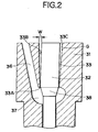
- FIG. 2 is an enlarged cross-sectional view showing the relevant portions of FIG. 1.
- FIG. 3 is an enlarged cross-sectional view of the relevant portions of a modification of the fuel injection valve for an internal combustion engine shown in FIG. 1.
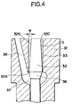
- FIG. 4 is an enlarged cross-sectional view of the relevant portions of a modification of a nozzle shown in FIG. 2.
- The present invention will now be described in greater detail in accordance with the attached drawings.
- FIG. 1 is a cross-sectional view showing an example of an embodiment of a fuel injection valve according to the present invention. That which is represented by
reference numeral 1 is a fuel injection valve for an internal combustion engine used in the Common Rail System for injecting/supplying fuel to a diesel internal combustion engine. Thefuel injection valve 1 is attached to a cylinder of an unillustrated diesel internal combustion engine, is for directly injecting/supplying, to the inside of the cylinder and at a required timing, just the required amount of high-pressure fuel supplied from an unillustrated common rail, and comprises anozzle 3 fixed to the leading end of anozzle holder 2 with aretaining nut 4. Anelectromagnetic valve 5 is disposed on a trailing end of thenozzle holder 2. - The
nozzle holder 2 includes ahollow body 22 in which aguide hole 21 is formed in the axial direction of thehollow body 22, and apressure pin 23 is disposed inside theguide hole 21 such that thepressure pin 23 is movable by theguide hole 21 in the axial direction of theguide hole 21. Anelastic spring 25 is housed inside aspring chamber 24 of thehollow body 22, and a later-describednozzle needle 32 is elastically urged by theelastic spring 25 in the direction of an injection holes35. That which is represented byreference numeral 26 is a passage disposed inside thehollow body 22 in order to supply the high-pressure fuel from the unillustrated common rail to thenozzle 3. - The
nozzle 3 includes anozzle body 31 and thenozzle needle 32. Thenozzle needle 32 is supported and guided, such that it is movable in its axial direction, by aguide hole 33 formed coaxially inside thenozzle body 31. A leadingend portion 32A of thenozzle needle 32 extends inside acylinder portion 34 disposed inside thenozzle body 31 in line with theguide hole 33, and the leading end of thenozzle needle 32 moves as a valve element that opens/closes theinjection hole 35. - Consequently, when the
nozzle needle 32 is retained in the position where it closes theinjection hole 35, fuel is not injected from thefuel injection valve 1. In contrast, when thenozzle needle 32 withdraws and is retained in the position where it opens theinjection hole 35, fuel is injected from thefuel injection valve 1. - An
oil pool 37 that stores the high-pressure fuel introduced thereto from thepassage 26 via apassage 36 is formed inside thenozzle body 31. Atapered portion 38 for causing force to act in a direction where thenozzle needle 32 is moved away from theinjection hole 35 due to the pressure of the high-pressure fuel inside theoil pool 37 is formed on thenozzle needle 32. - A
head 42, in wich adrain chamber 41 extending coaxially with theguide hole 21 in the axial direction of thehollow body 22 is formed facing down, is formed in a trailing end portion of thehollow body 22. Acontrol chamber 45 that is communicated with asupply pathway 43 in the radial direction and adrain pathway 44 in the axial direction is formed in thehead 42. Thesupply pathway 43 is communicated with anintake member 47 via a radial-direction pathway 46 inside thehollow body 22, and a bottom portion of thecontrol chamber 45 is formed by an upper end surface of thepressure pin 23. - A
ball 52 that works as a valve element is fixed to anarmature 51 of theelectromagnetic valve 5. Thearmature 51 is configured such that it is pushed down in the direction of thenozzle 3 by the force of an unillustrated valve spring, whereby theball 52 is pushed against an open end of thedrain pathway 44 to block off thedrain pathway 44. However, when theelectromagnetic valve 5 is urged, thearmature 51 moves in the direction away from thehead 42 counter to the force of the valve spring, whereby theball 52 moves away from the open end of thedrain pathway 44, and thedrain pathway 44 becomes communicated with thedrain chamber 41. - Consequently, when the
electromagnetic valve 5 is not being powered, the open end of thedrain pathway 44 is blocked off by theball 52, whereby thecontrol chamber 45 is filled with the high-pressure fuel. Thus, thenozzle needle 32 closes theinjection hole 35 due to thepressure pin 23, and fuel injection is not conducted. When theelectromagnetic valve 5 is powered, theball 52 moves away from the open end of thedrain pathway 44, the high-pressure fuel inside thecontrol chamber 45 escapes to the fuel low-pressure portion, and the pressure inside thecontrol chamber 45 drops, whereby fuel injection is conducted. When the power to theelectromagnetic valve 5 is cut off, thenozzle needle 32 is again returned to the position where it closes theinjection hole 35, and fuel injection ends. It will be noted that because the act of fuel injection from thenozzle 3 being carried out by controlling the power of theelectromagnetic valve 5 as described above is itself known, further detailed description thereof will be omitted. - A gap G between the
nozzle needle 32 and theguide hole 33 of thenozzle body 31 is an extremely slight gap such that it is substantially oil-tight. However, the pressure of the fuel stored in theoil pool 37 is extremely high, and the high-pressure fuel slightly leaks to the fuel low-pressure side of thenozzle holder 2 through the gap G. If a wax component is mixed into the fuel, the tendency arises for the wax component to be deposited and solidify in the gap G, particularly when thefuel injection valve 1 is operating at a low temperature, which causes thefuel injection valve 1 to operate defectively. - FIG. 2 is an enlarged view of the relevant portions of FIG. 1. As shown in FIG2, in the
fuel injevtion valve 1, at least part of the gap G formed between thenozzle needle 32 and theguide hole 33 has a tapered shape that widens toward thenozzle holder 2 in order to ensure that the aforementioned defective operation does not occur. - In the present embodiment, the
guide hole 33 is formed such that it includes atapered portion 33B that widens from oneend portion 33A at theoil pool 37 side toward thenozzle holder 2, so that the gap G has the tapered shape that widens toward thenozzle holder 2. As a result, a width W of the gap G is extremely narrow at the oneend portion 33A and linearly increases toward anotherend portion 33C of theguide hole 33. That is, the gap G widens like a skirt from the fuel high-pressure portion to the fuel low-pressure portion. - Because the
guide hole 33 is configured as described above, the width W of the gap G in the vicinity of the oneend portion 33A of theguide hole 33 is small, whereby the required oil-tightness can be maintained. Additionally, because the gap G widens like a skirt from the fuel high-pressure portion to the fuel low-pressure portion, when, for example, the wax component in fuel slightly leaking from theoil pool 37 to theguide hole 33 is deposited and solidifies when thefuel injection valve 1 is operating at a low temperature, the solidified matter can easily be moved in the direction of theother end portion 33C of the gap G (in the direction of the nozzle holder 2) and disccharged to the low-pressure portion of thenozzle holde 2. - Consequently, there is not the drawback where the solidified wax component remains inside the gap G, hinders the smooth operation of the
nozzle holder 2, and causes the fuel injection operation to become unstable, as has conventionally been the case. As a result, when fuel having wax mixed therein is used and the fuel injection valve is operated, stable operation can be expected even at a low temperature. - FIG. 3 is a diagram for describing a modification of the tapered portion of the
guide hole 33. In the example shown in FIG. 2, thetapered portion 33B is disposed across theentire guide hole 33, but in the example shown in FIG. 3, thetapered portion 33B is disposed on part of theguide hole 33. As a result, at least part of the gap G has a tapered shape that widens toward thenozzle holder 2. - That is, the vicinity of the one
end portion 33A of theguide hole 33 serves as anon-tapered portion 33D where the width of the gap G is constant and narrow, and atapered portion 33E corresponding to the taperedportion 33B is disposed only between thenon-tapered portion 33D and theother end portion 33C. - According to this configuration, by disposing the
non-tapered portion 33D, the advantage that the oil-tightness between theguide hole 33 and thenozzle needle 32 becomes higher is obtained in addition to the advantage according to the configuration of FIG. 2. - It will be noted that the tapered form of the tapered
portions - FIG. 4 is an enlarged cross-sectional view of the relevant portions of the
nozzle 3 for describing another modification of the gap G shown in FIG. 2. In the configuration shown in FIG. 4, the gap G formed between thenozzle needle 32 and theguide hole 33 is given the tapered shape that widens toward thenozzle holder 2 as a result of a taperedportion 32B being disposed in thenozzle needle 32 rather than as a result of tapering theguide hole 33. - It will be noted with respect to FIG. 4 that by disposing the tapered
portion 32B just on part of thenozzle needle 32, just part of the gap G can be tapered as shown in FIG. 3. - Moreover, at least part of the gap G formed between the
nozzle needle 32 and theguide hole 33 can be given the tapered shape that widens toward thenozzle holder 2 by tapering both theguide hole 33 and thenozzle needle 32. - According to the present invention, the invention is useful for the improvement of a fuel injection valve for an internal combustion engine that can maintain its operational stability, regardless of the running condition, when fuel having a heterogeneous component mixed therein is used and the fuel injection valve for an internal combustion engine is operated.
Claims (6)
- A fuel injection valve for an internal combustion engine comprising a nozzle fixed to a leading end portion of a nozzle holder, with the nozzle being configured such that a nozzle needle inserted into a guide hole inside a nozzle body is guided by the guide hole and moves in an axial direction to open/close an injection hole,
wherein at least part of a gap formed between the nozzle needle and the guide hole has a tapered shape that widens toward the nozzle holder. - The fuel injection valve for an internal combustion engine of claim 1, wherein the entire gap has a tapered shape that widens toward the nozzle holder.
- The fuel injection valve for an internal combustion engine of claim 1, wherein the tapered shape of the gap is a linear tapered shape.
- The fuel injection valve for an internal combustion engine of claim 2, wherein the tapered shape of the gap is a linear tapered shape.
- The fuel injection valve for an internal combustion engine of claim 1, 2, 3, or 4, wherein the gap has a tapered shape as a result of a tapered portion being formed in at least the guide hole.
- The fuel injection valve for an internal combustion engine of claim 1, 2, 3, or 4, wherein the gap has a tapered shape as a result of a tapered portion being formed in at least the nozzle needle.
Applications Claiming Priority (2)
| Application Number | Priority Date | Filing Date | Title |
|---|---|---|---|
| JP2003327214A JP4119812B2 (en) | 2003-09-19 | 2003-09-19 | Fuel injection valve |
| PCT/JP2004/013295 WO2005028853A1 (en) | 2003-09-19 | 2004-09-07 | Fuel injection valve for internal combustion engine |
Publications (3)
| Publication Number | Publication Date |
|---|---|
| EP1666720A1 true EP1666720A1 (en) | 2006-06-07 |
| EP1666720A4 EP1666720A4 (en) | 2010-08-04 |
| EP1666720B1 EP1666720B1 (en) | 2012-07-18 |
Family
ID=34372862
Family Applications (1)
| Application Number | Title | Priority Date | Filing Date |
|---|---|---|---|
| EP04772977A Expired - Lifetime EP1666720B1 (en) | 2003-09-19 | 2004-09-07 | Fuel injection valve for internal combustion engine |
Country Status (6)
| Country | Link |
|---|---|
| US (1) | US20070272771A1 (en) |
| EP (1) | EP1666720B1 (en) |
| JP (1) | JP4119812B2 (en) |
| KR (1) | KR100730862B1 (en) |
| CN (1) | CN100480505C (en) |
| WO (1) | WO2005028853A1 (en) |
Cited By (1)
| Publication number | Priority date | Publication date | Assignee | Title |
|---|---|---|---|---|
| US7367517B2 (en) | 2004-01-27 | 2008-05-06 | Denso Corporation | Fuel injection device inhibiting abrasion |
Families Citing this family (7)
| Publication number | Priority date | Publication date | Assignee | Title |
|---|---|---|---|---|
| DE102006053128A1 (en) * | 2006-11-10 | 2008-05-15 | Robert Bosch Gmbh | Injector for injecting fuel |
| JP2011185264A (en) * | 2010-02-11 | 2011-09-22 | Denso Corp | Injector |
| US8602319B2 (en) * | 2010-10-07 | 2013-12-10 | Caterpillar Inc. | Needle valve member with frustoconical guide segment and fuel injector using same |
| DE102010042688A1 (en) * | 2010-10-20 | 2012-04-26 | Robert Bosch Gmbh | fuel injector |
| DE102011003452A1 (en) * | 2011-02-01 | 2012-08-02 | Robert Bosch Gmbh | Fuel injection component |
| AT512893B1 (en) * | 2013-02-05 | 2013-12-15 | Bosch Gmbh Robert | Component with intermeshing high pressure holes |
| JP2020051368A (en) * | 2018-09-27 | 2020-04-02 | 日立建機株式会社 | Fuel injection device and work machine |
Family Cites Families (11)
| Publication number | Priority date | Publication date | Assignee | Title |
|---|---|---|---|---|
| JPS59130070U (en) * | 1983-02-18 | 1984-08-31 | ダイハツ工業株式会社 | internal combustion engine fuel injection valve |
| GB8318634D0 (en) * | 1983-07-09 | 1983-08-10 | Lucas Ind Plc | Fuel injection nozzles |
| CN85102659B (en) * | 1985-04-01 | 1986-11-12 | 大连工学院 | Multi-hole oil nozzle |
| JP2929713B2 (en) * | 1990-11-28 | 1999-08-03 | 株式会社デンソー | Fuel injection valve |
| CN2091361U (en) * | 1991-05-21 | 1991-12-25 | 梁少平 | Fuel spray nozzle for diesel engine direct-injection combustor |
| JPH07103106A (en) * | 1993-09-30 | 1995-04-18 | Hino Motors Ltd | Fuel injection device |
| DE29504608U1 (en) | 1995-03-17 | 1996-07-11 | Robert Bosch Gmbh, 70469 Stuttgart | Fuel injection valve for internal combustion engines |
| DE10102234A1 (en) * | 2001-01-19 | 2002-07-25 | Bosch Gmbh Robert | High pressure fuel supply unit, for an IC motor with fuel injection, has a drilling through the valve body to take a piston with a sealing section against the guide section of the drilling, with a hydraulic piston centering action |
| DE10147792C2 (en) * | 2001-09-27 | 2003-10-16 | Siemens Ag | Fuel injection valve |
| JP3969247B2 (en) * | 2001-11-06 | 2007-09-05 | 株式会社デンソー | Fuel injection valve |
| JP4066959B2 (en) * | 2004-01-27 | 2008-03-26 | 株式会社デンソー | Fuel injection device |
-
2003
- 2003-09-19 JP JP2003327214A patent/JP4119812B2/en not_active Expired - Fee Related
-
2004
- 2004-09-07 US US10/572,550 patent/US20070272771A1/en not_active Abandoned
- 2004-09-07 KR KR1020067005465A patent/KR100730862B1/en not_active Expired - Fee Related
- 2004-09-07 CN CNB2004800269667A patent/CN100480505C/en not_active Expired - Fee Related
- 2004-09-07 EP EP04772977A patent/EP1666720B1/en not_active Expired - Lifetime
- 2004-09-07 WO PCT/JP2004/013295 patent/WO2005028853A1/en not_active Ceased
Cited By (2)
| Publication number | Priority date | Publication date | Assignee | Title |
|---|---|---|---|---|
| US7367517B2 (en) | 2004-01-27 | 2008-05-06 | Denso Corporation | Fuel injection device inhibiting abrasion |
| US7635098B2 (en) | 2004-01-27 | 2009-12-22 | Denso Corporation | Fuel injection device inhibiting abrasion |
Also Published As
| Publication number | Publication date |
|---|---|
| CN1853042A (en) | 2006-10-25 |
| WO2005028853A1 (en) | 2005-03-31 |
| EP1666720B1 (en) | 2012-07-18 |
| CN100480505C (en) | 2009-04-22 |
| US20070272771A1 (en) | 2007-11-29 |
| KR100730862B1 (en) | 2007-06-20 |
| KR20060030123A (en) | 2006-04-07 |
| EP1666720A4 (en) | 2010-08-04 |
| JP2005090421A (en) | 2005-04-07 |
| JP4119812B2 (en) | 2008-07-16 |
Similar Documents
| Publication | Publication Date | Title |
|---|---|---|
| US7273186B2 (en) | Fuel injection device | |
| JP3707210B2 (en) | Fuel injection control device | |
| US6024297A (en) | Fuel injector | |
| EP0937891B1 (en) | Fuel Injector | |
| EP1666720A1 (en) | Fuel injection valve for internal combustion engine | |
| EP0818623A1 (en) | Injector | |
| JP3898083B2 (en) | Method for injecting lubricating oil into a cylinder of an internal combustion engine | |
| CN101529080A (en) | Injector for injecting fuel into combustion chambers of internal combustion engines | |
| EP1669591A1 (en) | Fuel injection valve | |
| JP2005344622A (en) | Fuel injection valve | |
| EP1717440A1 (en) | Fluid injection nozzle | |
| EP1722101A1 (en) | Seal structure of fuel passage and fuel injection valve having the seal structure | |
| EP0789143B1 (en) | Fuel injector for internal combustion engines | |
| KR20060122974A (en) | Seal structure of the fuel passage and fuel injection valve having the seal structure | |
| KR20160125894A (en) | A fuel valve for a large two-stroke self-igniting internal combustion engine | |
| JP4087817B2 (en) | Fuel injection valve | |
| EP1236883A2 (en) | Fuel system | |
| US20060016915A1 (en) | Fuel injector assembly | |
| JP5335608B2 (en) | Fuel injection device for internal combustion engine | |
| JPH11229998A (en) | Fuel injection device | |
| KR19990059335A (en) | Delivery valve of injection pump for diesel engine | |
| JP5942797B2 (en) | Fuel injection valve | |
| JP2510890Y2 (en) | Fuel injector | |
| RU2253032C2 (en) | Electrohydraulically controlled nozzle for fuel feed accumulator systems | |
| KR20010059847A (en) | Nipple for pouring oil in engine cylinder |
Legal Events
| Date | Code | Title | Description |
|---|---|---|---|
| PUAI | Public reference made under article 153(3) epc to a published international application that has entered the european phase |
Free format text: ORIGINAL CODE: 0009012 |
|
| 17P | Request for examination filed |
Effective date: 20060301 |
|
| AK | Designated contracting states |
Kind code of ref document: A1 Designated state(s): DE FR GB |
|
| DAX | Request for extension of the european patent (deleted) | ||
| RBV | Designated contracting states (corrected) |
Designated state(s): DE FR GB |
|
| A4 | Supplementary search report drawn up and despatched |
Effective date: 20100706 |
|
| RIC1 | Information provided on ipc code assigned before grant |
Ipc: F02M 61/16 20060101ALI20100630BHEP Ipc: F02M 61/12 20060101AFI20100630BHEP Ipc: F02M 55/00 20060101ALI20100630BHEP Ipc: F02M 61/10 20060101ALI20100630BHEP |
|
| 17Q | First examination report despatched |
Effective date: 20110316 |
|
| GRAP | Despatch of communication of intention to grant a patent |
Free format text: ORIGINAL CODE: EPIDOSNIGR1 |
|
| GRAS | Grant fee paid |
Free format text: ORIGINAL CODE: EPIDOSNIGR3 |
|
| GRAA | (expected) grant |
Free format text: ORIGINAL CODE: 0009210 |
|
| AK | Designated contracting states |
Kind code of ref document: B1 Designated state(s): DE FR GB |
|
| REG | Reference to a national code |
Ref country code: GB Ref legal event code: FG4D |
|
| REG | Reference to a national code |
Ref country code: DE Ref legal event code: R096 Ref document number: 602004038601 Country of ref document: DE Effective date: 20120913 |
|
| PLBE | No opposition filed within time limit |
Free format text: ORIGINAL CODE: 0009261 |
|
| STAA | Information on the status of an ep patent application or granted ep patent |
Free format text: STATUS: NO OPPOSITION FILED WITHIN TIME LIMIT |
|
| 26N | No opposition filed |
Effective date: 20130419 |
|
| REG | Reference to a national code |
Ref country code: DE Ref legal event code: R097 Ref document number: 602004038601 Country of ref document: DE Effective date: 20130419 |
|
| PGFP | Annual fee paid to national office [announced via postgrant information from national office to epo] |
Ref country code: GB Payment date: 20130920 Year of fee payment: 10 |
|
| PGFP | Annual fee paid to national office [announced via postgrant information from national office to epo] |
Ref country code: FR Payment date: 20130918 Year of fee payment: 10 Ref country code: DE Payment date: 20131121 Year of fee payment: 10 |
|
| REG | Reference to a national code |
Ref country code: DE Ref legal event code: R119 Ref document number: 602004038601 Country of ref document: DE |
|
| GBPC | Gb: european patent ceased through non-payment of renewal fee |
Effective date: 20140907 |
|
| REG | Reference to a national code |
Ref country code: DE Ref legal event code: R119 Ref document number: 602004038601 Country of ref document: DE Effective date: 20150401 |
|
| REG | Reference to a national code |
Ref country code: FR Ref legal event code: ST Effective date: 20150529 |
|
| PG25 | Lapsed in a contracting state [announced via postgrant information from national office to epo] |
Ref country code: GB Free format text: LAPSE BECAUSE OF NON-PAYMENT OF DUE FEES Effective date: 20140907 Ref country code: DE Free format text: LAPSE BECAUSE OF NON-PAYMENT OF DUE FEES Effective date: 20150401 |
|
| PG25 | Lapsed in a contracting state [announced via postgrant information from national office to epo] |
Ref country code: FR Free format text: LAPSE BECAUSE OF NON-PAYMENT OF DUE FEES Effective date: 20140930 |