EP1666302A1 - Retractable armrest for automotive vehicles. - Google Patents
Retractable armrest for automotive vehicles. Download PDFInfo
- Publication number
- EP1666302A1 EP1666302A1 EP05300949A EP05300949A EP1666302A1 EP 1666302 A1 EP1666302 A1 EP 1666302A1 EP 05300949 A EP05300949 A EP 05300949A EP 05300949 A EP05300949 A EP 05300949A EP 1666302 A1 EP1666302 A1 EP 1666302A1
- Authority
- EP
- European Patent Office
- Prior art keywords
- shaft
- door
- retractable armrest
- armrest according
- support
- Prior art date
- Legal status (The legal status is an assumption and is not a legal conclusion. Google has not performed a legal analysis and makes no representation as to the accuracy of the status listed.)
- Granted
Links
Images


Classifications
-
- B—PERFORMING OPERATIONS; TRANSPORTING
- B60—VEHICLES IN GENERAL
- B60N—SEATS SPECIALLY ADAPTED FOR VEHICLES; VEHICLE PASSENGER ACCOMMODATION NOT OTHERWISE PROVIDED FOR
- B60N2/00—Seats specially adapted for vehicles; Arrangement or mounting of seats in vehicles
- B60N2/24—Seats specially adapted for vehicles; Arrangement or mounting of seats in vehicles for particular purposes or particular vehicles
- B60N2/42—Seats specially adapted for vehicles; Arrangement or mounting of seats in vehicles for particular purposes or particular vehicles the seat constructed to protect the occupant from the effect of abnormal g-forces, e.g. crash or safety seats
- B60N2/4207—Seats specially adapted for vehicles; Arrangement or mounting of seats in vehicles for particular purposes or particular vehicles the seat constructed to protect the occupant from the effect of abnormal g-forces, e.g. crash or safety seats characterised by the direction of the g-forces
- B60N2/4235—Seats specially adapted for vehicles; Arrangement or mounting of seats in vehicles for particular purposes or particular vehicles the seat constructed to protect the occupant from the effect of abnormal g-forces, e.g. crash or safety seats characterised by the direction of the g-forces transversal
-
- B—PERFORMING OPERATIONS; TRANSPORTING
- B60—VEHICLES IN GENERAL
- B60N—SEATS SPECIALLY ADAPTED FOR VEHICLES; VEHICLE PASSENGER ACCOMMODATION NOT OTHERWISE PROVIDED FOR
- B60N2/00—Seats specially adapted for vehicles; Arrangement or mounting of seats in vehicles
- B60N2/75—Arm-rests
- B60N2/78—Arm-rests post or panel mounted
Definitions
- the present invention relates to a retractable armrest intended to be fixed on the inner wall of a motor vehicle door.
- the armrest folds automatically when the door opens and automatically opens when closed.
- the armrests of motor vehicles form protuberances inside the passenger compartment and thus pose a risk of injury to the driver and passengers in the event of an accident. This is particularly the case during a side impact. It is therefore important to propose solutions that reduce or eliminate the risks of such accidents.
- the sliding doors are usually not equipped with armrests because of their size or, where they exist, their width is very low which affects the comfort of passengers.
- the presence of comfortable armrests, therefore of sufficient width, would impose a relatively large shift of the door in the open position, which would require an expensive reinforcement of the support mechanism and opening of the sliding door.
- a retractable armrest is pivotally mounted on the inner wall of the sliding door.
- the armrest can take a retracted position in which it is applied against the inner wall of the door and an extended position in which it extends perpendicularly to the inner wall.
- the armrest When the door is opened, the armrest is automatically retracted.
- the armrest does not deploy automatically. It is necessary to deploy it after closing the door, to grasp it and bring it manually in its deployed position. This maneuver inevitably causes wear of the armrest where it is usually grasped. In addition, the presence of such an accessory is not always obvious for casual passengers.
- the armrest When in the extended position, the armrest can be folded only by a very precise gesture, that is by grasping the edge of the armrest and moving it by exerting a downward force. high. Any other effort applied to the armrest has no effect, the armrest remaining in the deployed position, which constitutes a risk of injury to the driver or passengers in the event of an accident. This is particularly the case during a side impact.
- the object of the invention is to overcome these disadvantages by providing a retractable armrest which folds when it undergoes a lateral force.
- the armrest unfolds and folds automatically, respectively closing and opening the door.
- the system is mechanically connected to the opening and closing kinematics of the door and therefore requires no intervention on the part of the passenger.
- the invention provides a retractable armrest intended to be fixed on the inner wall of an automobile door.
- the armrest comprises a support element pivotally mounted around a shaft between an extended position and a retracted position and means for passing said support element from the deployed position to the retracted position under the effect of a force lateral on said element.
- said means for passing the deployed position to the retracted position comprise elastic means for securing and separating said support member with said shaft.
- said resilient means comprise a holding tab integral with said shaft and a spring connecting on the one hand the support element and on the other hand the holding tab.
- this holding lug has the shape of a "U"
- one leg has a shoulder and the other leg is held in contact with a lug fixed on the support element.
- the spring has the shape of the Greek letter surrounding said shaft, one of the two ends of the spring resting on said lug and the other end resting on said shoulder.
- the support element advantageously has the form of a shelf pivoting about said shaft along one of its two longitudinal edges, the shaft and the longitudinal edge opposite the shaft being substantially contained in a plane inclined relative to to a horizontal plane.
- the inclined plane forms an angle greater than 9 ° with respect to a horizontal plane and the edge opposite the shaft has a rounded shape.
- the armrest comprises elastic means for returning the support element in the retracted position, advantageously constituted by a leaf spring mounted integrally with the shaft, the end of the blade being secured to the inner wall of the door.
- the support element When the door is sliding, the support element is mounted to pivot automatically between said extended position and said retracted position when the sliding door is respectively closed and open and the armrest comprises means for deploying and holding the element d support in deployed position.
- said deployment and holding means comprise a tilting tab integral with the shaft. This tab bears against an abutment fixed to the body of the car before the complete closure of the door and, as and when this closure, the tilt leg passes a first position, for which the element support is in a retracted position, substantially vertical, to a second position for which the support element is in the deployed position, substantially horizontal.
- the embodiment that will be described relates to an armrest attached to a sliding door of a motor vehicle, the support member being pivotally mounted automatically between an extended position and a retracted position when the sliding door is respectively closed and open.
- the invention may also relate to armrests mounted on hinged doors and / or do not include this automatic mechanism for deployment and automatic folding of the support element.
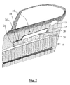
- a sliding door 10 the inner wall 12 is shown without its trim, conventionally comprises a metal structure or "box" and a space 14 for housing an inner handle.
- An armrest 16 consists mainly of a shaft 18, a support element 20 intended to receive the driver's or passenger's elbow or forearm and pivotally mounted around this shaft, of two supports 22 and 24 of the shaft 18 fixed on the inner wall 12 of the door, a tilt tab 26 fixed to one of the two ends of the shaft 18 and a leaf spring 28 attached to the other end of said tree.
- the shaft 18 is intended to be mounted substantially horizontally and parallel to the longitudinal axis of the vehicle.
- the support member 20 is in the deployed position, substantially horizontal, the tilting tab 26 being inclined relative to the vertical.
- FIG. 1 the support member 20 is in the deployed position, substantially horizontal, the tilting tab 26 being inclined relative to the vertical.
- the support element 20 is in the retracted position, substantially parallel to the inner wall of the door 10, the tilting tab 26 being also substantially parallel to the inner wall of the door 10.
- the tilting tab 26 keeps the support member 20 in the deployed position when it cooperates with a fixed stop (74 in Figures 6A and 6B) of the inner wall 12 of the door.
- the support member 20 is in the form of an approximately rectangular shelf with two side edges 30 and 32 (see FIGS. 3 and 4).
- the tablet is pivotally mounted around the shaft 18, along the edge 30.
- the thickness of the tablet is greater towards the longitudinal edge 30 and decreases progressively closer to the lateral edge 32.
- the element of support 20 is provided with two shoulders 34 and 36 which cooperate, in the deployed position, with two stops (not shown in FIG. 3 and reference 38 in FIG. 4) fixed on the inner wall 12 of the door 10.
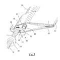
- the supports 24 and 26 each comprise a bearing 40 (FIGS. 3 and 6) and 80 (FIG. 6) allowing the shaft 18 to pivot in the supports.
- elastic means 42 make it possible to secure and detach the support element 20 with the shaft 18.
- These means comprise a lug 44 fixed on the side of the support element 20 and a U-shaped retaining lug 46, fixed on the shaft 18, provided with a shoulder 48 on one of the two legs of the "U", the other leg 50 being in contact with the lug 44.
- the elastic means also comprise a spring 52 having the shape of the Greek letter a. The spring 52 is fixed around the shaft 18. One of its two ends bears on the lug 44 and the other end bears on the shoulder 48.
- the operation of the armrest is as follows.
- the spring 52 resiliently secures the bearing element 20 with the shaft 18.
- the movement of the bearing element 20, which is pivotally mounted around the shaft 18, is connected to that of the shaft 18 by the bracket 46 and by the spring 50.
- the shaft 18 Starting from the extended position of the support member 20, as in Figures 3 and 5A, the shaft 18 by turning counterclockwise causes the rotation of the leg of 46, which causes the rotation of the support element 20 since the end 50 of the holding lug is in abutment on the lug 44.
- the bearing element 20 therefore passes to the folded position, substantially vertical , until the support member comes into contact with the inner wall 12 of the door.
- elastic means in the form of the leaf spring 28, tend to keep the bearing element in the folded position.
- the spring 28 is fixed to the end of the shaft 18, the end of its blade 54 being immobilized by a lug 56 fixed on the support 22, itself fixed on the inner wall of the door.
- the representation of the spring 28 in FIG. 4 corresponds to its maximum stress.
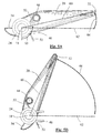
- Figures 5A and 5B are side views of the armrest and illustrate the principle of operation in case of side impact.
- the lateral edge 32 of the support element 20 and the shaft 18 are located substantially in the same plane, represented by the dotted line 60, this plane being inclined with respect to a horizontal plane represented by the dashed line 62.
- the inclination angle 64 is greater than a few degrees, of preferably close to 10 degrees.
- lateral force any force exerted on the longitudinal edge 32 at an angle 63 less than the value of the angle 64 plus 90 °, the angle 63 being measured ( Figure 5A) from the vertical, starting of the six o'clock position of the watch-hour hand and in the opposite direction of the movement of the hand.
- the support member moves to its folded position until reaching an angle 66 which corresponds to a folded position which no longer presents a danger of injury to the passenger or the driver, for example close to 66 degrees as illustrated on the Figure 5B.
- This angle depends on the value of the angle 64 (extended position) and the characteristics of the spring 52. The higher the value of the angle 64, the more easily the support element 20 pivots around the shaft 18. case of side impact.
- the door 10 is in the fully open position and extends parallel to the side of the body 70 of the vehicle.
- the support element 20 is in the retracted position, held in this position, on the one hand, by the return spring 28 acting on the axis 18 and, on the other hand, by the elastic means 42 solidifying the element 20 to support the shaft 18.
- the tilting tab 26, attached to the end of the shaft 18 and forming a rocker, is substantially vertical.
- the tilt tab 26 is positioned first facing a stop 74 secured to the body 70 of the vehicle.
- the door 10 closes completely by making a lateral movement towards the inside of the vehicle.
- the tilting tab 26 then comes into contact with the fixed stop 74, then rotates about the axis 76 which is the axis of rotation of the shaft 18.
- the tilting tab 26 being fixed to the shaft 18, The latter also rotates in the bearings 40 and 80, in the direction of the arrow 78, causing the pivoting of the support element 20 to reach the extended position when the vehicle door is completely closed.
- the support element 20 is held in the extended position by the tilting tab 26 when it comes into contact with the stop 74.
- the element of support 20 can remain constantly in the deployed position, whether the door is open or closed.
- the tilting tab 26, the stop 74 and the return spring are no longer necessary and the possibility of rotation of the shaft 18 is eliminated.
- This simplification does not prevent that in the event of a side impact, the support element 20 can swing towards its retracted position thanks to the resilient means 42 ( Figure 3) solidarisant and disengaging the shaft 18 and the support member 20. This tilting is favored by the inclination angle 64 ( Figure 5).
Landscapes
- Engineering & Computer Science (AREA)
- Aviation & Aerospace Engineering (AREA)
- Transportation (AREA)
- Mechanical Engineering (AREA)
- Seats For Vehicles (AREA)
- Passenger Equipment (AREA)
- Vehicle Step Arrangements And Article Storage (AREA)
- Lock And Its Accessories (AREA)
Abstract
Description
La présente invention a pour objet un accoudoir escamotable destiné à être fixé sur la paroi intérieure d'une porte de véhicule automobile. Lorsque la porte est coulissante, l'accoudoir se replie automatiquement à l'ouverture de la porte et se déploie automatiquement à la fermeture.The present invention relates to a retractable armrest intended to be fixed on the inner wall of a motor vehicle door. When the door is sliding, the armrest folds automatically when the door opens and automatically opens when closed.
Les accoudoirs des véhicules automobiles forment des protubérances à l'intérieur de l'habitacle et de ce fait présentent des risques de blessures pour le conducteur et les passagers en cas d'accident. C'est notamment le cas lors d'un choc latéral. Il est donc important de proposer des solutions qui diminuent ou suppriment les risques de tels accidents.The armrests of motor vehicles form protuberances inside the passenger compartment and thus pose a risk of injury to the driver and passengers in the event of an accident. This is particularly the case during a side impact. It is therefore important to propose solutions that reduce or eliminate the risks of such accidents.
Avec la demande croissante de véhicules automobiles du type monospace, les véhicules sont de plus en plus souvent équipés de portes coulissantes. Ces portes présentent de nombreux avantages parmi lesquels on peut citer une ouverture généralement supérieure par rapport aux portes classiques à charnières et donc un accès plus aisé à l'habitacle.With the increasing demand for cars of the minivan type, vehicles are increasingly equipped with sliding doors. These doors have many advantages among which can be mentioned an opening generally superior compared to conventional hinged doors and thus easier access to the passenger compartment.
Cependant, afin de faciliter leur ouverture, les portes coulissantes ne sont habituellement pas munies d'accoudoirs du fait de leur encombrement ou, lorsqu'ils existent, leur largeur est très faible ce qui nuit au confort des passagers. La présence d'accoudoirs confortables, donc de largeur suffisante, imposerait un décalage relativement important de la porte en position d'ouverture, ce qui nécessiterait un renforcement coûteux du mécanisme de soutien et d'ouverture de la porte coulissante.However, to facilitate their opening, the sliding doors are usually not equipped with armrests because of their size or, where they exist, their width is very low which affects the comfort of passengers. The presence of comfortable armrests, therefore of sufficient width, would impose a relatively large shift of the door in the open position, which would require an expensive reinforcement of the support mechanism and opening of the sliding door.
Une solution à ce problème est décrite dans la demande de brevet français n° FR-A-2813565 déposée le 7 septembre 2000 par la Demanderesse. Un accoudoir escamotable est monté pivotant sur la paroi intérieure de la porte coulissante. L'accoudoir peut prendre une position escamotée dans laquelle il est appliqué contre la paroi intérieure de la porte et une position déployée dans laquelle il s'étend perpendiculairement à la paroi intérieure. A l'ouverture de la porte, l'accoudoir est automatiquement escamoté. Cependant, à la fermeture de la porte, l'accoudoir ne se déploie pas automatiquement. Il est nécessaire, pour le déployer après fermeture de la porte, de le saisir et de l'amener manuellement dans sa position déployée. Cette manoeuvre provoque inévitablement une usure de l'accoudoir à l'endroit où il est habituellement saisi. De plus, la présence d'un tel accessoire n'est pas toujours évidente pour les passagers occasionnels.A solution to this problem is described in the French patent application No. FR-A-2813565 filed on September 7, 2000 by the Applicant. A retractable armrest is pivotally mounted on the inner wall of the sliding door. The armrest can take a retracted position in which it is applied against the inner wall of the door and an extended position in which it extends perpendicularly to the inner wall. When the door is opened, the armrest is automatically retracted. However, when closing the door, the armrest does not deploy automatically. It is necessary to deploy it after closing the door, to grasp it and bring it manually in its deployed position. This maneuver inevitably causes wear of the armrest where it is usually grasped. In addition, the presence of such an accessory is not always obvious for casual passengers.
Lorsqu'il est en position déployé, l'accoudoir ne peut être replié qu'en effectuant un geste bien précis, c'est-à-dire en saisissant le bord de l'accoudoir et en le déplaçant en exerçant une force de bas en haut. Tout autre effort appliqué sur l'accoudoir est sans effet, l'accoudoir restant en position déployée, ce qui constitue un risque de blessure pour le conducteur ou les passagers en cas d'accident. C'est notamment le cas lors d'un choc latéral.When in the extended position, the armrest can be folded only by a very precise gesture, that is by grasping the edge of the armrest and moving it by exerting a downward force. high. Any other effort applied to the armrest has no effect, the armrest remaining in the deployed position, which constitutes a risk of injury to the driver or passengers in the event of an accident. This is particularly the case during a side impact.
Le but de l'invention est de pallier ces inconvénients en proposant un accoudoir escamotable qui se replie lorsqu'il subit un effort latéral. De plus, lorsque la porte est coulissante, l'accoudoir se déploie et se replie automatiquement, respectivement à la fermeture et à l'ouverture de la porte. Le système est relié mécaniquement à la cinématique d'ouverture et de fermeture de la porte et ne nécessite donc aucune intervention de la part du passager.The object of the invention is to overcome these disadvantages by providing a retractable armrest which folds when it undergoes a lateral force. In addition, when the door is sliding, the armrest unfolds and folds automatically, respectively closing and opening the door. The system is mechanically connected to the opening and closing kinematics of the door and therefore requires no intervention on the part of the passenger.
De façon plus précise, l'invention propose un accoudoir escamotable destiné à être fixé sur la paroi interne d'une porte d'automobile. L'accoudoir comporte un élément d'appui monté pivotant autour d'un arbre entre une position déployée et une position rétractée et des moyens de passage dudit élément d'appui de la position déployée vers la position rétractée sous l'effet d'un effort latéral sur ledit élément.More specifically, the invention provides a retractable armrest intended to be fixed on the inner wall of an automobile door. The armrest comprises a support element pivotally mounted around a shaft between an extended position and a retracted position and means for passing said support element from the deployed position to the retracted position under the effect of a force lateral on said element.
Selon un mode de réalisation avantageux, lesdits moyens de passage de la position déployée vers la position rétractée comportent des moyens élastiques pour solidariser et désolidariser ledit élément d'appui avec ledit arbre.According to an advantageous embodiment, said means for passing the deployed position to the retracted position comprise elastic means for securing and separating said support member with said shaft.
Selon une forme de réalisation, lesdits moyens élastiques comportent une patte de maintien solidaire dudit arbre et un ressort reliant d'une part l'élément d'appui et d'autre part la patte de maintien. De façon avantageuse, cette patte de maintien a la forme d'un "U" dont l'une des jambes comporte un épaulement et dont l'autre jambe est maintenue en contact avec un ergot fixé sur l'élément d'appui. Le ressort a la forme de la lettre grecque a entourant ledit arbre, l'une des deux extrémités du ressort s'appuyant sur ledit ergot et l'autre extrémité s'appuyant sur ledit épaulement.According to one embodiment, said resilient means comprise a holding tab integral with said shaft and a spring connecting on the one hand the support element and on the other hand the holding tab. Advantageously, this holding lug has the shape of a "U", one leg has a shoulder and the other leg is held in contact with a lug fixed on the support element. The spring has the shape of the Greek letter surrounding said shaft, one of the two ends of the spring resting on said lug and the other end resting on said shoulder.
L'élément d'appui a avantageusement la forme d'une tablette pivotant autour dudit arbre le long d'un de ses deux bords longitudinaux, l'arbre et le bord longitudinal opposé à l'arbre étant sensiblement contenus dans un plan incliné par rapport à un plan horizontal. De préférence, le plan incliné forme un angle supérieur à 9° par rapport à un plan horizontal et le bord opposé à l'arbre a une forme arrondie.The support element advantageously has the form of a shelf pivoting about said shaft along one of its two longitudinal edges, the shaft and the longitudinal edge opposite the shaft being substantially contained in a plane inclined relative to to a horizontal plane. Preferably, the inclined plane forms an angle greater than 9 ° with respect to a horizontal plane and the edge opposite the shaft has a rounded shape.
Selon un mode de réalisation, l'accoudoir comporte des moyens élastiques de rappel de l'élément d'appui en position rétractée, avantageusement constitués par un ressort à lame monté solidaire de l'arbre, l'extrémité de la lame étant maintenue solidaire de la paroi intérieure de la porte.According to one embodiment, the armrest comprises elastic means for returning the support element in the retracted position, advantageously constituted by a leaf spring mounted integrally with the shaft, the end of the blade being secured to the inner wall of the door.
Lorsque la porte est coulissante, l'élément d'appui est monté pivotant automatiquement entre ladite position déployée et ladite position rétractée lorsque la porte coulissante est respectivement fermée et ouverte et l'accoudoir comporte des moyens de déploiement et de maintien de l'élément d'appui en position déployée.When the door is sliding, the support element is mounted to pivot automatically between said extended position and said retracted position when the sliding door is respectively closed and open and the armrest comprises means for deploying and holding the element d support in deployed position.
Selon un mode de réalisation préféré, lesdits moyens de déploiement et de maintien comportent une patte de basculement solidaire de l'arbre. Cette patte vient en appui contre une butée fixée à la caisse de l'automobile avant la fermeture complète de la porte et, au fur et à mesure de cette fermeture, la patte de basculement passe d'une première position, pour laquelle l'élément d'appui est en position rétractée, sensiblement verticale, à une deuxième position pour laquelle l'élément d'appui est en position déployée, sensiblement horizontale.According to a preferred embodiment, said deployment and holding means comprise a tilting tab integral with the shaft. This tab bears against an abutment fixed to the body of the car before the complete closure of the door and, as and when this closure, the tilt leg passes a first position, for which the element support is in a retracted position, substantially vertical, to a second position for which the support element is in the deployed position, substantially horizontal.
D'autres caractéristiques et avantages de l'invention ressortiront de la description suivante, donnée uniquement à titre d'exemple et faite en référence aux dessins annexés sur lesquels :
- les figures 1 et 2 illustrent en perspective un mode de réalisation d'un accoudoir escamotable, monté sur une porte coulissante, dans la position respectivement déployée (figure 1) et rétractée (figure 2);
- les figures 3 et 4 montrent des détails de réalisation;
- les figures 5A et 5B représentent une vue de coté des moyens élastiques permettant de solidariser/désolidariser l'élément d'appui, respectivement en position embrayée (figure 5A) et débrayée (figure 5B);
- les figures 6A et 6B représentent schématiquement la cinématique du mode de réalisation illustré sur les figures précédentes, la porte étant ouverte et l'élément d'appui relevé (figure 6A), puis la porte étant fermée et l'élément d'appui abaissé (figure 6B).
- Figures 1 and 2 illustrate in perspective an embodiment of a retractable armrest, mounted on a sliding door, in the respectively deployed position (Figure 1) and retracted (Figure 2);
- Figures 3 and 4 show details of embodiment;
- 5A and 5B show a side view of the resilient means for securing / disengaging the support element, respectively in the engaged position (Figure 5A) and disengaged (Figure 5B);
- FIGS. 6A and 6B schematically represent the kinematics of the embodiment illustrated in the preceding figures, with the door open and the support element raised (FIG. 6A), then the door being closed and the support element lowered ( Figure 6B).
Le mode de réalisation qui va être décrit concerne un accoudoir fixé sur une porte coulissante d'un véhicule automobile, l'élément d'appui étant monté pivotant automatiquement entre une position déployée et une position rétractée lorsque la porte coulissante est respectivement fermée et ouverte. Cependant, l'invention peut également concerner des accoudoirs montés sur des portes à charnières et/ou ne pas inclure ce mécanisme automatique de déploiement et de repliement automatique de l'élément d'appui.The embodiment that will be described relates to an armrest attached to a sliding door of a motor vehicle, the support member being pivotally mounted automatically between an extended position and a retracted position when the sliding door is respectively closed and open. However, the invention may also relate to armrests mounted on hinged doors and / or do not include this automatic mechanism for deployment and automatic folding of the support element.
Sur les figures 1 et 2, une porte coulissante 10, dont la paroi intérieure 12 est représentée sans sa garniture, comporte de façon classique une structure métallique ou "caisson" et un espace 14 pour loger une poignée intérieure. Un accoudoir 16 est constitué principalement d'un arbre 18, d'un élément d'appui 20 destiné à recevoir le coude ou l'avant-bras du conducteur ou du passager et monté pivotant autour de cet arbre, de deux supports 22 et 24 de l'arbre 18 fixés sur la paroi intérieure 12 de la porte, d'une patte de basculement 26 fixée à l'une des deux extrémités de l'arbre 18 et d'un ressort à lame 28 fixé à l'autre extrémité dudit arbre. L'arbre 18 est destiné à être monté sensiblement horizontalement et parallèle à l'axe longitudinal du véhicule. Sur la figure 1, l'élément d'appui 20 est en position déployée, sensiblement horizontale, la patte de basculement 26 étant inclinée par rapport à la verticale. Sur la figure 2, l'élément d'appui 20 est en position rétractée, sensiblement parallèle à la paroi interne de la porte 10, la patte de basculement 26 étant elle aussi sensiblement parallèle à la paroi interne de la porte 10. La patte de basculement 26 permet de maintenir l'élément d'appui 20 en position déployée lorsqu'elle coopère avec une butée fixe (74 sur les figures 6A et 6B) de la paroi intérieure 12 de la porte.In Figures 1 and 2, a sliding
L'élément d'appui 20 a la forme d'une tablette approximativement rectangulaire avec deux bords latéraux 30 et 32 (voir figures 3 et 4). La tablette est montée pivotante autour de l'arbre 18, le long du bord 30. L'épaisseur de la tablette est plus grande vers le bord longitudinal 30 et va en diminuant progressivement en se rapprochant du bord latéral 32. L'élément d'appui 20 est muni de deux épaulements 34 et 36 qui coopèrent, en position déployée, avec deux butées (non représentée sur la figure 3 et référence 38 sur la figure 4) fixées sur la paroi intérieure 12 de la porte 10.The
Les supports 24 et 26 comportent chacun un palier 40 (figures 3 et 6) et 80 (figures 6) permettant à l'arbre 18 de pivoter dans les supports.The supports 24 and 26 each comprise a bearing 40 (FIGS. 3 and 6) and 80 (FIG. 6) allowing the
Sur la figure 3, des moyens élastiques 42 permettent de solidariser et de désolidariser l'élément d'appui 20 avec l'arbre 18. Ces moyens comprennent un ergot 44 fixé sur le coté de l'élément d'appui 20 et d'une patte de maintien 46 en forme de "U", fixée sur l'arbre 18, munie d'un épaulement 48 sur l'une des deux jambes du "U", l'autre jambe 50 étant en contact avec l'ergot 44. Les moyens élastiques comprennent également un ressort 52 ayant la forme de la lettre grecque a. Le ressort 52 est fixé autour de l'arbre 18. L'une de ses deux extrémités prend appui sur l'ergot 44 et l'autre extrémité prend appui sur l'épaulement 48.In FIG. 3, elastic means 42 make it possible to secure and detach the
Le fonctionnement de l'accoudoir est le suivant. Le ressort 52 solidarise de façon élastique l'élément d'appui 20 avec l'arbre 18. Le mouvement de l'élément d'appui 20, qui est monté pivotant autour de l'arbre 18, est lié à celui de l'arbre 18 par la patte de maintien 46 et par le ressort 50. En partant de la position déployée de l'élément d'appui 20, comme sur les figures 3 et 5A, l'arbre 18 en tournant en sens contraire des aiguilles d'une montre entraîne la rotation de la patte de maintien 46, lequel entraîne la rotation de l'élément d'appui 20 puisque l'extrémité 50 de la patte de maintien est en butée sur l'ergot 44. L'élément d'appui 20 passe donc vers la position repliée, sensiblement verticale, jusqu'à ce que l'élément d'appui vienne en contact avec la paroi intérieure 12 de la porte. En sens contraire, lorsque l'arbre 18 tourne dans le sens des aiguilles d'une montre, la patte de maintien 46 tourne également, en entraînant l'élément d'appui 20 puisque l'ergot 44 est maintenu en contact de l'extrémité 50 de la patte de maintien 46 par le ressort 52. L'élément d'appui passe donc de la position repliée à la position déployée, correspondant au contact des épaulements 34 et 36 avec leurs butées respectives (butée 38 pour l'épaulement 36).The operation of the armrest is as follows. The
Comme représenté sur la figure 4, des moyens élastiques, sous forme du ressort à lame 28, tendent à maintenir l'élément d'appui en position repliée. Le ressort 28 est fixé à l'extrémité de l'arbre 18, l'extrémité de sa lame 54 étant immobilisée par un ergot 56 fixé sur le support 22, lui-même fixé sur la paroi intérieure de la porte. La représentation du ressort 28 sur la figure 4 correspond à sa contrainte maximale.As shown in FIG. 4, elastic means, in the form of the
Les figures 5A et 5B sont des vues de coté de l'accoudoir et illustrent le principe de fonctionnement en cas de choc latéral. Selon une caractéristique de l'invention, lorsque l'élément d'appui 20 est en position déployée (figure 5A), le bord latéral 32 de l'élément d'appui 20 et l'arbre 18 sont situés sensiblement dans un même plan, représenté par le trait en pointillés 60, ce plan étant incliné par rapport à un plan horizontal représenté par le trait en pointillés 62. L'angle d'inclinaison 64 est supérieur à quelques degrés, de préférence voisin de 10 degrés. Lorsqu'un effort latéral est appliqué sur le bord latéral 32, en cas de choc latéral par exemple, l'élément d'appui 20 tourne autour de l'arbre 18, contre l'action exercée par le ressort 52 (figure 5B). Par effort latéral on entend toute force s'exerçant sur le bord longitudinal 32 selon un angle 63 inférieur à la valeur de l'angle 64 plus 90°, l'angle 63 étant mesuré (figure 5A) à partir de la verticale, en partant de la position six heures de l'aiguille des heures d'une montre et dans le sens inverse du mouvement de l'aiguille. L'élément d'appui se déplace vers sa position repliée jusqu'à atteindre un angle 66 qui correspond à une position repliée qui ne présente plus de danger de blessures pour le passager ou le conducteur, par exemple voisin de 66 degrés comme illustré sur la figure 5B. Cet angle dépend de la valeur de l'angle 64 (position déployée) et des caractéristiques du ressort 52. Plus la valeur de l'angle 64 est élevée, plus l'élément d'appui 20 pivote facilement autour de l'arbre 18 en cas de choc latéral.Figures 5A and 5B are side views of the armrest and illustrate the principle of operation in case of side impact. According to one characteristic of the invention, when the
La cinématique du déploiement et du repliement automatique de l'accoudoir est illustrée sur les figures 6A et 6B, l'accoudoir étant monté sur la porte coulissante 10 d'un véhicule automobile.The kinematics of deployment and automatic folding of the armrest is illustrated in Figures 6A and 6B, the armrest being mounted on the sliding
Sur la figure 6A, la porte 10 est en position complètement ouverte et s'étend parallèlement au coté de la caisse 70 du véhicule. L'élément d'appui 20 est en position rétractée, maintenu dans cette position , d'une part, par le ressort de rappel 28 agissant sur l'axe 18 et, d'autre part, par les moyens élastiques 42 solidarisant l'élément d'appui 20 à l'arbre 18. La patte de basculement 26, fixée à l'extrémité de l'arbre 18 et formant balancier, est sensiblement verticale.In Figure 6A, the
Pour fermer la porte 10, on la déplace dans le sens de la flèche 72 sur des rails (non représentés) portés par la caisse du véhicule, jusqu'à atteindre la position de fermeture illustrée sur la figure 6B. Au cours de ce déplacement, la patte de basculement 26 se positionne d'abord en regard d'une butée 74 solidaire de la caisse 70 du véhicule. La porte 10 se ferme complètement en effectuant un mouvement latéral, vers l'intérieur du véhicule. La patte de basculement 26 vient alors en contact avec la butée fixe 74, puis tourne autour de l'axe 76 qui est l'axe de rotation de l'arbre 18. La patte de basculement 26 étant fixée à l'arbre 18, ce dernier tourne également dans les paliers 40 et 80, dans le sens de la flèche 78, provoquant le pivotement de l'élément d'appui 20 jusqu'à atteindre la position déployée lorsque la porte du véhicule est complètement fermée.To close the
En sens inverse, au début de l'ouverture de la porte, la patte de basculement 26 s'éloigne et se désolidarise de la butée 74. Sous l'effet du ressort de rappel 28, l'arbre 18 pivote dans les paliers 40 et 80, approximativement d'un quart de tour, dans le sens contraire de la flèche 78, en entraînant l'élément d'appui 18. Ce dernier retrouve alors sa position rétractée de la figure 6A. On remarque que le déploiement et le repliement de l'accoudoir s'effectuent automatiquement respectivement lors de l'ouverture et de la fermeture de la porte, indépendamment du mode d'ouverture, manuel ou électrique.In the opposite direction, at the beginning of the opening of the door, the
Dans le mode de réalisation décrit, le maintien de l'élément d'appui 20 en position déployée est assuré par la patte de basculement 26 lorsqu'elle vient au contact de la butée 74. Pour une porte à charnières, l'élément d'appui 20 peut rester constamment en position déployée, que la porte soit ouverte ou fermée. Pour cela, la patte de basculement 26, la butée 74 et le ressort de rappel ne sont plus nécessaires et la possibilité de rotation de l'arbre 18 est supprimée. Cette simplification n'empêche pas qu'en cas de choc latéral, l'élément d'appui 20 peut basculer vers sa position rétractée grâce aux moyens élastiques 42 (figure 3) solidarisant et désolidarisant l'arbre 18 et l'élément d'appui 20. Ce basculement est favorisé par l'angle d'inclinaison 64 (figure 5).In the embodiment described, the
Claims (12)
Applications Claiming Priority (1)
| Application Number | Priority Date | Filing Date | Title |
|---|---|---|---|
| FR0452823A FR2878477B1 (en) | 2004-12-01 | 2004-12-01 | RETRACTABLE ARMREST FOR MOTOR VEHICLES |
Publications (2)
| Publication Number | Publication Date |
|---|---|
| EP1666302A1 true EP1666302A1 (en) | 2006-06-07 |
| EP1666302B1 EP1666302B1 (en) | 2008-03-26 |
Family
ID=34951370
Family Applications (1)
| Application Number | Title | Priority Date | Filing Date |
|---|---|---|---|
| EP05300949A Not-in-force EP1666302B1 (en) | 2004-12-01 | 2005-11-18 | Retractable armrest for automotive vehicles. |
Country Status (4)
| Country | Link |
|---|---|
| EP (1) | EP1666302B1 (en) |
| AT (1) | ATE390322T1 (en) |
| DE (1) | DE602005005607T2 (en) |
| FR (1) | FR2878477B1 (en) |
Cited By (3)
| Publication number | Priority date | Publication date | Assignee | Title |
|---|---|---|---|---|
| US8020923B2 (en) | 2008-08-25 | 2011-09-20 | GM Global Technology Operations LLC | Motor vehicle with a sliding door and an adjustable armrest |
| US8403398B2 (en) | 2008-08-25 | 2013-03-26 | GM Global Technology Operations LLC | Motor vehicle with a sliding door and an adjustable armrest |
| CN107985150A (en) * | 2017-12-12 | 2018-05-04 | 延锋海纳川汽车饰件系统有限公司 | A kind of folded turnover formula automobile door trim fupport arm |
Families Citing this family (4)
| Publication number | Priority date | Publication date | Assignee | Title |
|---|---|---|---|---|
| US7384092B2 (en) * | 2006-09-27 | 2008-06-10 | Gm Global Technology Operations, Inc. | Selectively retractable armrest for a slidable door |
| FR2924649A3 (en) * | 2007-12-05 | 2009-06-12 | Renault Sas | Folding armrest for side door of terrestrial motor vehicle, has upper end receiving user elbow, where armrest is mounted to limit rotation of armrest by manual activation units provoking simple inclination of armrest in utilization position |
| FR2933642B1 (en) * | 2008-07-10 | 2011-12-02 | Peugeot Citroen Automobiles Sa | RETRACTABLE ARMREST FOR AUTOMOTIVE VEHICLE DOOR, WITH RETRACTABLE CONTROL BY DOOR OPEN DETECTION |
| US9162598B2 (en) * | 2013-12-10 | 2015-10-20 | Ford Global Technologies, Llc | Moveable vehicle armrest assembly |
Citations (11)
| Publication number | Priority date | Publication date | Assignee | Title |
|---|---|---|---|---|
| US1674205A (en) * | 1926-10-28 | 1928-06-19 | Johnson James Pierson | Arm rest |
| US1719716A (en) * | 1927-07-16 | 1929-07-02 | Montage Charles Anthony | Arm rest for automobile seats |
| DE586562C (en) * | 1931-11-27 | 1933-10-23 | Oscar Zwierzina | Armrests for motor vehicle and aircraft drivers |
| FR1043146A (en) * | 1951-10-18 | 1953-11-06 | Anciens Ets Hotchkiss & Cie | Articulated armrest, especially for motor cars |
| US3038757A (en) * | 1958-12-13 | 1962-06-12 | Auto Union Gmbh | Inner door handle for automobiles |
| FR1518824A (en) * | 1967-02-07 | 1968-03-29 | Peugeot | Advanced vehicle armrest |
| US3489457A (en) * | 1967-10-23 | 1970-01-13 | Clyde Pike | Side window arm shade |
| DE3626897A1 (en) * | 1986-08-08 | 1988-02-11 | Porsche Ag | Device for adjusting an armrest of a motor vehicle, aeroplane or the like |
| DE4002242A1 (en) * | 1990-01-26 | 1991-08-01 | Bayerische Motoren Werke Ag | Height adjustable armrest - has rest pivoted to door handle and compensation provided for change in length between pivot axis of handle and armrest |
| US6145919A (en) * | 1999-02-26 | 2000-11-14 | Lear Corporation | Automatic folding armrest for sliding vehicle door |
| FR2813565A1 (en) | 2000-09-07 | 2002-03-08 | Peugeot Citroen Automobiles Sa | Automobile sliding door comprises door casing and armrest which pivots between retracted and deployed positions |
-
2004
- 2004-12-01 FR FR0452823A patent/FR2878477B1/en not_active Expired - Fee Related
-
2005
- 2005-11-18 EP EP05300949A patent/EP1666302B1/en not_active Not-in-force
- 2005-11-18 AT AT05300949T patent/ATE390322T1/en not_active IP Right Cessation
- 2005-11-18 DE DE602005005607T patent/DE602005005607T2/en active Active
Patent Citations (11)
| Publication number | Priority date | Publication date | Assignee | Title |
|---|---|---|---|---|
| US1674205A (en) * | 1926-10-28 | 1928-06-19 | Johnson James Pierson | Arm rest |
| US1719716A (en) * | 1927-07-16 | 1929-07-02 | Montage Charles Anthony | Arm rest for automobile seats |
| DE586562C (en) * | 1931-11-27 | 1933-10-23 | Oscar Zwierzina | Armrests for motor vehicle and aircraft drivers |
| FR1043146A (en) * | 1951-10-18 | 1953-11-06 | Anciens Ets Hotchkiss & Cie | Articulated armrest, especially for motor cars |
| US3038757A (en) * | 1958-12-13 | 1962-06-12 | Auto Union Gmbh | Inner door handle for automobiles |
| FR1518824A (en) * | 1967-02-07 | 1968-03-29 | Peugeot | Advanced vehicle armrest |
| US3489457A (en) * | 1967-10-23 | 1970-01-13 | Clyde Pike | Side window arm shade |
| DE3626897A1 (en) * | 1986-08-08 | 1988-02-11 | Porsche Ag | Device for adjusting an armrest of a motor vehicle, aeroplane or the like |
| DE4002242A1 (en) * | 1990-01-26 | 1991-08-01 | Bayerische Motoren Werke Ag | Height adjustable armrest - has rest pivoted to door handle and compensation provided for change in length between pivot axis of handle and armrest |
| US6145919A (en) * | 1999-02-26 | 2000-11-14 | Lear Corporation | Automatic folding armrest for sliding vehicle door |
| FR2813565A1 (en) | 2000-09-07 | 2002-03-08 | Peugeot Citroen Automobiles Sa | Automobile sliding door comprises door casing and armrest which pivots between retracted and deployed positions |
Cited By (4)
| Publication number | Priority date | Publication date | Assignee | Title |
|---|---|---|---|---|
| US8020923B2 (en) | 2008-08-25 | 2011-09-20 | GM Global Technology Operations LLC | Motor vehicle with a sliding door and an adjustable armrest |
| US8403398B2 (en) | 2008-08-25 | 2013-03-26 | GM Global Technology Operations LLC | Motor vehicle with a sliding door and an adjustable armrest |
| CN107985150A (en) * | 2017-12-12 | 2018-05-04 | 延锋海纳川汽车饰件系统有限公司 | A kind of folded turnover formula automobile door trim fupport arm |
| CN107985150B (en) * | 2017-12-12 | 2023-11-14 | 延锋海纳川汽车饰件系统有限公司 | Folding and overturning type automobile door trim arm support |
Also Published As
| Publication number | Publication date |
|---|---|
| EP1666302B1 (en) | 2008-03-26 |
| DE602005005607T2 (en) | 2009-06-10 |
| ATE390322T1 (en) | 2008-04-15 |
| FR2878477A1 (en) | 2006-06-02 |
| DE602005005607D1 (en) | 2008-05-08 |
| FR2878477B1 (en) | 2008-05-30 |
Similar Documents
| Publication | Publication Date | Title |
|---|---|---|
| EP1666302B1 (en) | Retractable armrest for automotive vehicles. | |
| EP1890917A1 (en) | Device for controlling the opening of the engine hood of a vehicle, particularly for protecting the head of a pedestrian in the event of a collision therewith | |
| EP2042388B1 (en) | Device for protecting pedestrians and vehicle equipped with such a device | |
| EP2489536A1 (en) | Door system for a motor vehicle, in particular for an automobile. | |
| EP1613495B1 (en) | Retractable parcel shelf system for a convertible vehicle with a folding roof | |
| EP0895895B1 (en) | Seat for automotive vehicle | |
| WO2010081952A1 (en) | Motor vehicle comprising an opening roof mounted such that it can move on the roof of this vehicle | |
| FR3022510A1 (en) | VEHICLE INTERIOR ASSEMBLY HAVING A TABLET | |
| WO2010109083A1 (en) | Vehicle door leaf comprising a retractable handle, and vehicle fitted with such a door leaf | |
| FR2876065A1 (en) | Lateral sliding door for motor vehicle, has armrest formed of support unit extended by arm that is extended by lug which is terminated by plate cooperating with stop to bring and maintain armrest in deployed position when door is closed | |
| EP1893444B1 (en) | Arrangement of a rear parcel shelf inside a motor vehicle | |
| EP3649015B1 (en) | Motor vehicle fitted with a load guard and comprising a seat backrest retention device | |
| EP2208628B1 (en) | Device forming a glazed part of a motor vehicle roof, fitted with a deflector | |
| EP0169113B1 (en) | Mounting device, especially of a radio receiver disposed inside a motor vehicle | |
| EP2288518B1 (en) | Load space cover device with an improved pull handle | |
| FR2925422A1 (en) | Object e.g. bottle, maintaining device for e.g. lateral door of motor vehicle, has strip with free end such that end passes from rest position in which strip is plated against wall to usage position in which strip is plated against object | |
| EP0352176B1 (en) | Locking device for a cover of a box, e.g. vehicle glove compartment | |
| FR3071201B1 (en) | CENTRAL PILLAR ARMREST | |
| FR2872465A1 (en) | Dash board e.g. glove compartment, arrangement for motor vehicle, has storage space with movable walls to define storage volume when walls are in unfolded position, and storage cavity is set free, when walls are in storage position | |
| FR2876076A1 (en) | Boot structure for motor vehicle, has boot panel with arm for tilting panel between open and closed positions, where arm actuates control unit to control tilting of rear window between closed and open positions after tilting panel | |
| FR3095170A1 (en) | Locking device for a vehicle rear seat back that can be unlocked remotely by motorized means | |
| FR3110523A1 (en) | Retractable awning for motor vehicle trunk and motor vehicle comprising a retractable awning | |
| FR2922826A1 (en) | MOTOR VEHICLE SEAT FOLDING FORWARD | |
| EP1443166A1 (en) | Side door hinge mechanism in motor vehicle | |
| EP1470953A1 (en) | Locking device for the rear bench of an automotive vehicle. |
Legal Events
| Date | Code | Title | Description |
|---|---|---|---|
| PUAI | Public reference made under article 153(3) epc to a published international application that has entered the european phase |
Free format text: ORIGINAL CODE: 0009012 |
|
| AK | Designated contracting states |
Kind code of ref document: A1 Designated state(s): AT BE BG CH CY CZ DE DK EE ES FI FR GB GR HU IE IS IT LI LT LU LV MC NL PL PT RO SE SI SK TR |
|
| AX | Request for extension of the european patent |
Extension state: AL BA HR MK YU |
|
| 17P | Request for examination filed |
Effective date: 20060626 |
|
| AKX | Designation fees paid |
Designated state(s): AT BE BG CH CY CZ DE DK EE ES FI FR GB GR HU IE IS IT LI LT LU LV MC NL PL PT RO SE SI SK TR |
|
| GRAP | Despatch of communication of intention to grant a patent |
Free format text: ORIGINAL CODE: EPIDOSNIGR1 |
|
| GRAS | Grant fee paid |
Free format text: ORIGINAL CODE: EPIDOSNIGR3 |
|
| GRAA | (expected) grant |
Free format text: ORIGINAL CODE: 0009210 |
|
| AK | Designated contracting states |
Kind code of ref document: B1 Designated state(s): AT BE BG CH CY CZ DE DK EE ES FI FR GB GR HU IE IS IT LI LT LU LV MC NL PL PT RO SE SI SK TR |
|
| REG | Reference to a national code |
Ref country code: GB Ref legal event code: FG4D Free format text: NOT ENGLISH |
|
| REG | Reference to a national code |
Ref country code: IE Ref legal event code: FG4D Free format text: LANGUAGE OF EP DOCUMENT: FRENCH Ref country code: CH Ref legal event code: EP |
|
| REF | Corresponds to: |
Ref document number: 602005005607 Country of ref document: DE Date of ref document: 20080508 Kind code of ref document: P |
|
| PG25 | Lapsed in a contracting state [announced via postgrant information from national office to epo] |
Ref country code: FI Free format text: LAPSE BECAUSE OF FAILURE TO SUBMIT A TRANSLATION OF THE DESCRIPTION OR TO PAY THE FEE WITHIN THE PRESCRIBED TIME-LIMIT Effective date: 20080326 |
|
| PG25 | Lapsed in a contracting state [announced via postgrant information from national office to epo] |
Ref country code: AT Free format text: LAPSE BECAUSE OF FAILURE TO SUBMIT A TRANSLATION OF THE DESCRIPTION OR TO PAY THE FEE WITHIN THE PRESCRIBED TIME-LIMIT Effective date: 20080326 |
|
| NLV1 | Nl: lapsed or annulled due to failure to fulfill the requirements of art. 29p and 29m of the patents act | ||
| PG25 | Lapsed in a contracting state [announced via postgrant information from national office to epo] |
Ref country code: LV Free format text: LAPSE BECAUSE OF FAILURE TO SUBMIT A TRANSLATION OF THE DESCRIPTION OR TO PAY THE FEE WITHIN THE PRESCRIBED TIME-LIMIT Effective date: 20080326 Ref country code: SI Free format text: LAPSE BECAUSE OF FAILURE TO SUBMIT A TRANSLATION OF THE DESCRIPTION OR TO PAY THE FEE WITHIN THE PRESCRIBED TIME-LIMIT Effective date: 20080326 Ref country code: PL Free format text: LAPSE BECAUSE OF FAILURE TO SUBMIT A TRANSLATION OF THE DESCRIPTION OR TO PAY THE FEE WITHIN THE PRESCRIBED TIME-LIMIT Effective date: 20080326 |
|
| REG | Reference to a national code |
Ref country code: IE Ref legal event code: FD4D |
|
| PG25 | Lapsed in a contracting state [announced via postgrant information from national office to epo] |
Ref country code: CZ Free format text: LAPSE BECAUSE OF FAILURE TO SUBMIT A TRANSLATION OF THE DESCRIPTION OR TO PAY THE FEE WITHIN THE PRESCRIBED TIME-LIMIT Effective date: 20080326 Ref country code: SE Free format text: LAPSE BECAUSE OF FAILURE TO SUBMIT A TRANSLATION OF THE DESCRIPTION OR TO PAY THE FEE WITHIN THE PRESCRIBED TIME-LIMIT Effective date: 20080626 Ref country code: PT Free format text: LAPSE BECAUSE OF FAILURE TO SUBMIT A TRANSLATION OF THE DESCRIPTION OR TO PAY THE FEE WITHIN THE PRESCRIBED TIME-LIMIT Effective date: 20080901 Ref country code: ES Free format text: LAPSE BECAUSE OF FAILURE TO SUBMIT A TRANSLATION OF THE DESCRIPTION OR TO PAY THE FEE WITHIN THE PRESCRIBED TIME-LIMIT Effective date: 20080707 Ref country code: SK Free format text: LAPSE BECAUSE OF FAILURE TO SUBMIT A TRANSLATION OF THE DESCRIPTION OR TO PAY THE FEE WITHIN THE PRESCRIBED TIME-LIMIT Effective date: 20080326 |
|
| PG25 | Lapsed in a contracting state [announced via postgrant information from national office to epo] |
Ref country code: NL Free format text: LAPSE BECAUSE OF FAILURE TO SUBMIT A TRANSLATION OF THE DESCRIPTION OR TO PAY THE FEE WITHIN THE PRESCRIBED TIME-LIMIT Effective date: 20080326 Ref country code: RO Free format text: LAPSE BECAUSE OF FAILURE TO SUBMIT A TRANSLATION OF THE DESCRIPTION OR TO PAY THE FEE WITHIN THE PRESCRIBED TIME-LIMIT Effective date: 20080326 |
|
| PG25 | Lapsed in a contracting state [announced via postgrant information from national office to epo] |
Ref country code: IS Free format text: LAPSE BECAUSE OF FAILURE TO SUBMIT A TRANSLATION OF THE DESCRIPTION OR TO PAY THE FEE WITHIN THE PRESCRIBED TIME-LIMIT Effective date: 20080726 |
|
| REG | Reference to a national code |
Ref country code: GB Ref legal event code: 746 Effective date: 20081222 |
|
| PG25 | Lapsed in a contracting state [announced via postgrant information from national office to epo] |
Ref country code: DK Free format text: LAPSE BECAUSE OF FAILURE TO SUBMIT A TRANSLATION OF THE DESCRIPTION OR TO PAY THE FEE WITHIN THE PRESCRIBED TIME-LIMIT Effective date: 20080326 Ref country code: IE Free format text: LAPSE BECAUSE OF FAILURE TO SUBMIT A TRANSLATION OF THE DESCRIPTION OR TO PAY THE FEE WITHIN THE PRESCRIBED TIME-LIMIT Effective date: 20080326 Ref country code: LT Free format text: LAPSE BECAUSE OF FAILURE TO SUBMIT A TRANSLATION OF THE DESCRIPTION OR TO PAY THE FEE WITHIN THE PRESCRIBED TIME-LIMIT Effective date: 20080326 |
|
| PLBE | No opposition filed within time limit |
Free format text: ORIGINAL CODE: 0009261 |
|
| STAA | Information on the status of an ep patent application or granted ep patent |
Free format text: STATUS: NO OPPOSITION FILED WITHIN TIME LIMIT |
|
| 26N | No opposition filed |
Effective date: 20081230 |
|
| PG25 | Lapsed in a contracting state [announced via postgrant information from national office to epo] |
Ref country code: BG Free format text: LAPSE BECAUSE OF FAILURE TO SUBMIT A TRANSLATION OF THE DESCRIPTION OR TO PAY THE FEE WITHIN THE PRESCRIBED TIME-LIMIT Effective date: 20080626 Ref country code: EE Free format text: LAPSE BECAUSE OF FAILURE TO SUBMIT A TRANSLATION OF THE DESCRIPTION OR TO PAY THE FEE WITHIN THE PRESCRIBED TIME-LIMIT Effective date: 20080326 |
|
| BERE | Be: lapsed |
Owner name: PEUGEOT CITROEN AUTOMOBILES SA Effective date: 20081130 |
|
| PG25 | Lapsed in a contracting state [announced via postgrant information from national office to epo] |
Ref country code: MC Free format text: LAPSE BECAUSE OF NON-PAYMENT OF DUE FEES Effective date: 20081130 |
|
| PG25 | Lapsed in a contracting state [announced via postgrant information from national office to epo] |
Ref country code: IT Free format text: LAPSE BECAUSE OF FAILURE TO SUBMIT A TRANSLATION OF THE DESCRIPTION OR TO PAY THE FEE WITHIN THE PRESCRIBED TIME-LIMIT Effective date: 20080326 |
|
| PG25 | Lapsed in a contracting state [announced via postgrant information from national office to epo] |
Ref country code: CY Free format text: LAPSE BECAUSE OF FAILURE TO SUBMIT A TRANSLATION OF THE DESCRIPTION OR TO PAY THE FEE WITHIN THE PRESCRIBED TIME-LIMIT Effective date: 20080326 Ref country code: BE Free format text: LAPSE BECAUSE OF NON-PAYMENT OF DUE FEES Effective date: 20081130 |
|
| REG | Reference to a national code |
Ref country code: CH Ref legal event code: PL |
|
| PG25 | Lapsed in a contracting state [announced via postgrant information from national office to epo] |
Ref country code: HU Free format text: LAPSE BECAUSE OF FAILURE TO SUBMIT A TRANSLATION OF THE DESCRIPTION OR TO PAY THE FEE WITHIN THE PRESCRIBED TIME-LIMIT Effective date: 20080927 Ref country code: LU Free format text: LAPSE BECAUSE OF NON-PAYMENT OF DUE FEES Effective date: 20081118 |
|
| PG25 | Lapsed in a contracting state [announced via postgrant information from national office to epo] |
Ref country code: TR Free format text: LAPSE BECAUSE OF FAILURE TO SUBMIT A TRANSLATION OF THE DESCRIPTION OR TO PAY THE FEE WITHIN THE PRESCRIBED TIME-LIMIT Effective date: 20080326 |
|
| PG25 | Lapsed in a contracting state [announced via postgrant information from national office to epo] |
Ref country code: GR Free format text: LAPSE BECAUSE OF FAILURE TO SUBMIT A TRANSLATION OF THE DESCRIPTION OR TO PAY THE FEE WITHIN THE PRESCRIBED TIME-LIMIT Effective date: 20080627 Ref country code: LI Free format text: LAPSE BECAUSE OF NON-PAYMENT OF DUE FEES Effective date: 20091130 Ref country code: CH Free format text: LAPSE BECAUSE OF NON-PAYMENT OF DUE FEES Effective date: 20091130 |
|
| PGFP | Annual fee paid to national office [announced via postgrant information from national office to epo] |
Ref country code: DE Payment date: 20121025 Year of fee payment: 8 |
|
| PGFP | Annual fee paid to national office [announced via postgrant information from national office to epo] |
Ref country code: GB Payment date: 20121025 Year of fee payment: 8 |
|
| PGFP | Annual fee paid to national office [announced via postgrant information from national office to epo] |
Ref country code: FR Payment date: 20131121 Year of fee payment: 9 |
|
| GBPC | Gb: european patent ceased through non-payment of renewal fee |
Effective date: 20131118 |
|
| PG25 | Lapsed in a contracting state [announced via postgrant information from national office to epo] |
Ref country code: DE Free format text: LAPSE BECAUSE OF NON-PAYMENT OF DUE FEES Effective date: 20140603 |
|
| REG | Reference to a national code |
Ref country code: DE Ref legal event code: R119 Ref document number: 602005005607 Country of ref document: DE Effective date: 20140603 |
|
| PG25 | Lapsed in a contracting state [announced via postgrant information from national office to epo] |
Ref country code: GB Free format text: LAPSE BECAUSE OF NON-PAYMENT OF DUE FEES Effective date: 20131118 |
|
| REG | Reference to a national code |
Ref country code: FR Ref legal event code: ST Effective date: 20150731 |
|
| PG25 | Lapsed in a contracting state [announced via postgrant information from national office to epo] |
Ref country code: FR Free format text: LAPSE BECAUSE OF NON-PAYMENT OF DUE FEES Effective date: 20141201 |