EP1664663B1 - Jagdkugel mit verringertem aerodynamischem widerstand - Google Patents
Jagdkugel mit verringertem aerodynamischem widerstand Download PDFInfo
- Publication number
- EP1664663B1 EP1664663B1 EP04787338A EP04787338A EP1664663B1 EP 1664663 B1 EP1664663 B1 EP 1664663B1 EP 04787338 A EP04787338 A EP 04787338A EP 04787338 A EP04787338 A EP 04787338A EP 1664663 B1 EP1664663 B1 EP 1664663B1
- Authority
- EP
- European Patent Office
- Prior art keywords
- bullet
- conical
- ogival
- nose
- ogive
- Prior art date
- Legal status (The legal status is an assumption and is not a legal conclusion. Google has not performed a legal analysis and makes no representation as to the accuracy of the status listed.)
- Active
Links
- 238000010008 shearing Methods 0.000 abstract 1
- 239000002184 metal Substances 0.000 description 9
- 229910052751 metal Inorganic materials 0.000 description 9
- 238000000034 method Methods 0.000 description 8
- RYGMFSIKBFXOCR-UHFFFAOYSA-N Copper Chemical compound [Cu] RYGMFSIKBFXOCR-UHFFFAOYSA-N 0.000 description 3
- 229910052802 copper Inorganic materials 0.000 description 3
- 239000010949 copper Substances 0.000 description 3
- 238000002788 crimping Methods 0.000 description 3
- 239000000463 material Substances 0.000 description 3
- 229910001369 Brass Inorganic materials 0.000 description 2
- 239000010951 brass Substances 0.000 description 2
- 238000007796 conventional method Methods 0.000 description 2
- 238000010304 firing Methods 0.000 description 2
- 229910001092 metal group alloy Inorganic materials 0.000 description 2
- 235000001674 Agaricus brunnescens Nutrition 0.000 description 1
- 239000004429 Calibre Substances 0.000 description 1
- 229910000881 Cu alloy Inorganic materials 0.000 description 1
- 229910000978 Pb alloy Inorganic materials 0.000 description 1
- 229910000831 Steel Inorganic materials 0.000 description 1
- HCHKCACWOHOZIP-UHFFFAOYSA-N Zinc Chemical compound [Zn] HCHKCACWOHOZIP-UHFFFAOYSA-N 0.000 description 1
- 229910045601 alloy Inorganic materials 0.000 description 1
- 239000000956 alloy Substances 0.000 description 1
- 229910052782 aluminium Inorganic materials 0.000 description 1
- XAGFODPZIPBFFR-UHFFFAOYSA-N aluminium Chemical compound [Al] XAGFODPZIPBFFR-UHFFFAOYSA-N 0.000 description 1
- 239000010953 base metal Substances 0.000 description 1
- 230000015572 biosynthetic process Effects 0.000 description 1
- 230000006378 damage Effects 0.000 description 1
- 230000006837 decompression Effects 0.000 description 1
- 230000001627 detrimental effect Effects 0.000 description 1
- 230000003467 diminishing effect Effects 0.000 description 1
- 239000006185 dispersion Substances 0.000 description 1
- 230000000694 effects Effects 0.000 description 1
- 239000012634 fragment Substances 0.000 description 1
- 238000013467 fragmentation Methods 0.000 description 1
- 238000006062 fragmentation reaction Methods 0.000 description 1
- CNKHSLKYRMDDNQ-UHFFFAOYSA-N halofenozide Chemical compound C=1C=CC=CC=1C(=O)N(C(C)(C)C)NC(=O)C1=CC=C(Cl)C=C1 CNKHSLKYRMDDNQ-UHFFFAOYSA-N 0.000 description 1
- 210000000003 hoof Anatomy 0.000 description 1
- 230000003116 impacting effect Effects 0.000 description 1
- 230000000977 initiatory effect Effects 0.000 description 1
- 238000012423 maintenance Methods 0.000 description 1
- 238000004519 manufacturing process Methods 0.000 description 1
- 230000035515 penetration Effects 0.000 description 1
- 239000004033 plastic Substances 0.000 description 1
- 239000003381 stabilizer Substances 0.000 description 1
- 239000010959 steel Substances 0.000 description 1
- 238000004804 winding Methods 0.000 description 1
- 239000011701 zinc Substances 0.000 description 1
- 229910052725 zinc Inorganic materials 0.000 description 1
Images


Classifications
-
- F—MECHANICAL ENGINEERING; LIGHTING; HEATING; WEAPONS; BLASTING
- F42—AMMUNITION; BLASTING
- F42B—EXPLOSIVE CHARGES, e.g. FOR BLASTING, FIREWORKS, AMMUNITION
- F42B12/00—Projectiles, missiles or mines characterised by the warhead, the intended effect, or the material
- F42B12/02—Projectiles, missiles or mines characterised by the warhead, the intended effect, or the material characterised by the warhead or the intended effect
- F42B12/34—Projectiles, missiles or mines characterised by the warhead, the intended effect, or the material characterised by the warhead or the intended effect expanding before or on impact, i.e. of dumdum or mushroom type
Definitions
- the present invention relates to ammunition for small arms, medium and large caliber, and more particularly a new bullet, especially for hunting weapons, with reduced aerodynamic drag and providing improved terminal efficiency, particularly on soft target.
- the most conventional ammunition for hunting weapons is usually leaded bullets with lead alloy cores, the front of which has a flattened or rounded head. According to a variant, some balls have a central channel in the warhead.
- the patent US 3,881,421 describes a bullet whose head is hollowed out to cause it to flatten upon impact on the target.
- These ammunition generally have the disadvantage of a high loss of speed on the trajectory and a significant mass loss at impact on the target due to a dislocation of the bullet.
- Balls of the same type comprising, on the front end of the warhead, a piece of plastic or other materials intended to improve the aerodynamics of the bullet and the accuracy of the shot, as in the patent. CH 625043 .
- these balls fragment and expand weakly on impact on the target, which affects their terminal efficiency.
- Requirement WO 0045120 discloses the preamble of claim 1 and discloses a bullet having an enlarged base metal core, supporting an open ogival head envelope prominent with respect to the central core.
- the patent US 5,259,320 shows an example of a lead-free monometallic bullet, with a central channel located in the warhead, which exhibits rupture primers intended to control the expansion of the warhead and its winding in petals, upon impact on target.
- This technique has the disadvantage of random expansion, and a risk of fragmentation of the formed petals.
- the method of manufacture of this type of ball by cold stamping causes dynamic imbalances that result in a dispersion of shots.
- the diameter of the nose of the warhead is between 40 and 50% of the maximum diameter of the bullet, which gives it a significant aerodynamic drag.
- These bullets are therefore mainly intended for so-called "beat" firing, at short and medium distances, less than 150 m for rifles, and of the order of 50 to 60 m for shotguns. Beyond these distances, and mainly with low initial velocity bullets, the impact velocity on the target is too low to cause a radial expansion of the bullet body which is necessary for satisfactory efficiency.
- the present invention precisely aims to optimize the ballistics of a lead-free metal ball of the above type to obtain the lowest possible aerodynamic drag trajectory while maintaining excellent terminal efficiency on the target by avoiding losses of mass of the metal body of the ball, at great distances, which can be of the order of 300 m.
- the subject of the present invention is therefore a small, medium or large caliber weapon bullet, at the caliber of the weapon or under-calibrated, of the type comprising an internal arrow of rigidity greater than or equal to that of the body of the bullet, arranged in a hole drilled in the bullet body along its axis, which is distinguished in that the internal arrow is recessed relative to the orifice of the hole, the latter, located on the axis, is a blind hole of a diameter less than that of the internal arrow, and the wall of the ogival head of the bullet body comprises one or more deformation primers made by a constriction of the original head near the orifice of the hole.
- the deformation primers of the ogival head are made by a throat of the ogival head, separating the ogival nose from the rear part of the ogive.
- the bullet of the invention has in its front part a conical or cylindro-conical cavity, delimited on its large base by the front face of the internal arrow, and opening on the ogival nose of the bullet by a small orifice, preferably circular, located in the axis.
- the warhead forming the head of the bullet is very profiled, so as to provide as little aerodynamic drag as possible, and for this purpose, the orifice of the hole enclosing the internal arrow has a diameter smaller than that of the internal arrow, the ratio d 1 / d of the diameter d 1 of the orifice to the diameter d of the internal deflection being between 0.1: 1 and 0.9: 1.
- the nose of the ogive comprises a flat whose outer diameter d 2 is such that the ratio d 2 / d is between 0.3: 1 and 1.5: 1.
- the ratio d 2 / d is between 0.6: 1 and 1: 1, while the diameter d 1 of the orifice is such that the ratio d 1 / d is from about 0.3: 1 to about 0.6: 1.
- the deformation primers made in the wall of the ogival head are intended to facilitate the deformation and opening of the nose of the warhead at impact on the target, to cause a deformation by "mushrooming".
- This ogival shape has an ogival nose surrounding the orifice communicating with the conical or cylindro-conical cavity, and a rear portion, which cooperate to minimize and reduce to the utmost any discontinuity of the flow of air in flight which could cause detachment of Mach wave detrimental to aerodynamic drag.
- these deformation primers can be preferably made in the form of a constriction in the outer wall of the warhead, separating the ogival nose, open on the front, of the rear part of the warhead. , so that the section of the base of the ogival nose is slightly greater than that of the front of the rear part of the ogive.
- This throttling is preferably located at the base of the conical or cylindro-conical internal cavity formed in front of the internal arrow, or slightly in front of this base, and more preferably at the junction line of the conical surfaces and cylindrical when the internal cavity is cylindro-conical.
- the constriction made in the wall of the warhead to form the primer deformation is materialized by a recess between the base of the ogival nose and the front end of the rear part of the warhead, and the radial height of this recess , for medium-sized bales, is generally between 0.05 and 1 mm, and preferably between 0.1 and 0.5 mm.
- the theoretical profile of the ogival nose and the rear part of the ogive meet in a line of tangency located at a distance between 1/5 and 4/5, preferably between 1/3 and 2/3, of the height of the rear part of the warhead.
- the rear part of the ogive has a convex profile.
- the internal cavity has a cylindro-conical shape, where the cylinder and the cone are coaxial, joined by the large base of the cone, the latter being disposed in front of the cylinder.
- the internal cavity has a bit-conical shape, the two cones being joined by their large base, the small base of the rear truncated cone being closed by the internal arrow.
- the front of the internal arrow slightly protrudes into the internal cavity formed in the ogival nose, that is to say that the frustoconical or cylindrical wall of the base of the internal cavity comes into contact with the outer surface of the arrow slightly behind the front end thereof.
- This has the effect of forming an annular volume that can serve as a primer for expansion of the ball head during impact on the target.
- the internal arrow inserted into the body of the metal bullet can be made of one or more elements. When constituted by a single cylindrical element, it preferably has a plurality of longitudinal or transverse ribs which improve the bond with the bullet body.
- the hole drilled in the bullet body, into which the internal arrow is inserted, may be through or blind, and preferably blind.
- the ball according to the present invention has the advantage of substantially reducing the aerodynamic drag on the trajectory, while ensuring the control of the deformation of the body of the bullet during the impact on the target, even at great distance.
- the aerodynamic drag coefficient is reduced about half for projectile velocities of the order of Mach 2.
- the low aerodynamic trajectory drag allows the bullet of the invention to maintain a high speed until the impact on a target at a distance of more than 300 m.
- the ball then deforms in a controlled manner by wrapping around its axis, impacting the soft parts of the target, and ensures the effective destruction of the hard parts of said target, even at great distances, which may be greater than 300 m in the case of caliber bullets.
- the bullet of the invention is preferably a lead-free metal bullet.
- the body of the ball may be metal or metal alloy selected from copper and copper alloys, and preferably a brass containing 5 to 40% zinc.
- the arrow or metal insert in the axis of the ball may be made of metal or metal alloy selected from steel, copper and alloys of aluminum or copper, for example a brass.
- the ball of the invention can be manufactured by conventional techniques, for example by first forming a ball provided with an axial cylindrical hole opening on the front, by introducing the internal arrow, and then forming the ogival nose by cold mechanical forming.
- the invention applies to bullets gyro stabilized or stabilized by tail, the caliber of the weapon or sub-calibrated associated with a launch pad.
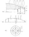
- the bullet with the caliber of the weapon is of the metal monobloc type and comprises at its rear part a necking of the base (1), at its central part a body (2), and at its front part a stepped warhead (3).
- An inner deflected boom (4) the surface of which carries longitudinal ribs (5), is placed in a hole drilled in the axis of the bullet body and passing through the warhead (3).
- the ball carrying the internal arrow (4) is inserted into a case provided with a primer and a load, of conventional type, not shown.
- the ogival head (3) of the bullet is very profiled to reduce as much as possible the aerodynamic drag, and the diameters d 1 of the orifice (8) and d 2 of the flat (6) of the nose (7) which surrounds it are as small as possible.
- the diameter d 2 of the flat is slightly smaller than the diameter d of the internal arrow (4), the ratio d 2 : d being close to 0.8: 1, while the diameter d 1 of the orifice is such that the ratio d 1: d is about 0.5.
- the internal cylindro-conical cavity (9) thus delimited, opens on the nose (7) of the ogive (3) through the orifice (8) of circular shape.
- the large base of the nose of the stepped ogive (3) has a diameter d 4 slightly greater than the front diameter d3 of the rear part of the warhead.
- This arrangement in relation to the shape of the internal cavity (9) causes a thinning of the wall of the ogival head, thereby generating a line of mechanical weakness (11).
- This line of weakness (11) makes it possible to control the deformation of the ogival head (3) during the impact on the target.
- the Figure 2 shows the beginning of the deformation of the stepped warhead (3) during the impact on the target.
- the force (F) is exerted on the base of the flat (6) of the nose (7) of the staggered warhead (3) of the bullet.
- the nose (7) crushes gradually causing a radial expansion of the wall of the nose, the point of articulation is located in line with the line of mechanical weakness (11).
- This movement leads to deformation by radial expansion of the front of the portion (10) of the warhead (3), causing the formation of a conical inlet (12) which then generates the "mushrooming" of the ball.
- the soft parts of the target are engaged in the cavity (9) and in the conical inlet (12), and they thus create a significant radial pressure Pi on the internal walls of the cavity (9).
- This pressure combined with the line of mechanical weakness (11), contributes to the initiation of the process of "mushrooming" or expansion of the ball.
- the Figure 3 shows the evolution of the "mushrooming" process of the ball.
- the conical inlet (12) continues to open, while the ogival head (3) of the ball wraps around the axis of the bullet, revealing the front tip of the internal shaft (4) whose rigidity is greater than the body of the ball.
- the wall of the ogival head of the ball is completely inverted and the body of the ball then has a mushroom shape without loss of material, while the internal arrow can be possibly detached.
- the diameter of the bullet body thus deformed is approximately three times the original diameter.
- the Figure 4 represents the invention applied to a sub-calibrated bullet (13) carrying a stabilizer (14) on its rear part, housed in a throwing shoe (15), the assembly being placed, in a usual manner, in a primed sleeve and charged, not shown.
- the stepped nose (16) comprises a nose (17) whose large base has a diameter (identical to the diameter d 4 of the Figure 1 ) greater than the diameter of the front of the rear portion (18) of the warhead (16) (identical to the d-meter d 3 of the Figure 1 ).
- the internal cavity (19) is substantially identical to the internal cavity (9) of the ball of the Figure 1 , and works in the same way to the impact on the target.
- This under-calibrated bullet can be used in a shotgun with a smooth or weakly scratched gun for firing distances generally not exceeding 100 meters. This ball is stabilized on trajectory by the empenne (14).
- the internal cavity (9) is constituted by two conical frustums joined by their large base, so that the frustoconical surface (20) of the rear part and the frustoconical surface (21) of the part before are joined along a line in the immediate vicinity of the constriction at the base of the ogival nose.
- the distance l 1 between the plane of the orifice (8) and the junction line (22) between the two frustoconical surfaces (20) and (21) is equal to approximately 1.5 times the distance l 2 between the same line of the plane of the connecting line between the frustoconical surface (20) and the surface of the internal shaft (4).
- the frustoconical surface (20) joins the outer surface of the inner shaft (4) slightly behind the front end thereof.
- the junction (22) between the two frustoconical surfaces (20) and (21) is made in a rounded surface, or the frustoconical surface (20) is replaced by a spherical ring surface that is connected without rupture. on the frustoconical surface (21).
- the Figure 6 represents, in half-view outside, a variant of the ball of the Figure 1 , having a crimping groove (23) on the theoretical connection (24) of the rear part (10) of the ogival head with the body (2) of the bale.
- This rear portion (10) of the ogive has a convex profile.
- the crimping groove (23) is here of rectangular section. It is intended to facilitate the establishment and maintenance of the ball in the cartridge.
- the body (2) of the ball may include decompression grooves.
- the orifice (8) may have rupture primers (25) which facilitate the partial opening of the ogival nose (7), thus accelerating the deformation of the head of the bullet during the impact on the target.
Claims (10)
- Kugel für eine Klein-, Mittel- oder Großkaliberwaffe, die dem Kaliber der Waffe entspricht oder unterkalibrig ist, vom Typ, der einen inneren Pfeil (4) mit einer Steifigkeit umfasst, die jener des Kugelkörpers gleich oder höher als dieser ist, wobei der Pfeil in einem in dem Kugelkörper entlang seiner Achse ausgebohrten Loch angeordnet ist, dadurch gekennzeichnet, dass der innere Pfeil (4) in Bezug auf die Öffnung (8) des Lochs nach hinten versetzt ist, wobei das Loch, das sich auf der Achse befindet, ein Sackloch mit einem geringeren Durchmesser als der innere Pfeil (4) ist, und dass die Wand des spitzbogenförmigen Kopfs (3) des Kugelkörpers (2) in der Nähe der Öffnung des Lochs ein oder mehrere durch eine Einschnürung des spitzbogenförmigen Kopfs ausgebildete Verformungsauslöseelemente umfasst.
- Kugel nach Anspruch 1, dadurch gekennzeichnet, dass sie in ihrem vorderen Teil einen Hohlraum (9) in konischer oder zylindrisch-konischer Form umfasst, deren große Grundfläche durch die Vorderfläche des Pfeils (4) im Inneren begrenzt ist.
- Kugel nach Anspruch 1, dadurch gekennzeichnet, dass die Verformungsauslöseelemente des spitzbogenförmigen Kopfs durch eine Einschnürung des spitzbogenförmigen Kopfs ausgebildet sind, welche die spitzbogenförmige Spitze (7) vom hinteren Teil (10) der Geschossspitze (7) trennt.
- Kugel nach Anspruch 3, dadurch gekennzeichnet, dass der Querschnitt der großen Grundfläche der spitzbogenförmigen Spitze (7) etwas größer als jener des Vorderteils des hinteren Teils (10) der Geschossspitze ist.
- Kugel nach einem der Ansprüche 3 und 4, dadurch gekennzeichnet, dass die Einschnürung auf der Höhe der Grundfläche des konischen oder zylindrisch-konischen inneren Hohlraums (9), der vor dem inneren Pfeil (4) ausgebildet ist, oder etwas vor dieser Grundfläche angeordnet ist.
- Kugel nach einem der Ansprüche 3 und 4, dadurch gekennzeichnet, dass der innere Hohlraum (9) eine zylindrisch-konische Form aufweist und die Einschnürung auf der Höhe der Verbindungslinie (22) der konischen und der zylindrischen Fläche angeordnet ist.
- Kugel nach einem der Ansprüche 3 bis 6, dadurch gekennzeichnet, dass die in der Wand der Geschossspitze ausgebildete Einschnürung eine Zurückversetzung zwischen der großen Grundfläche der spitzbogenförmigen Spitze (7) und dem vorderen Ende des hinteren Teils (10) der Geschossspitze bildet, wobei die Höhe dieser Seitenverschiebung zwischen 0,05 und 1 mm liegt.
- Kugel nach Anspruch 1, dadurch gekennzeichnet, dass das Verhältnis des Durchmessers d1 der Öffnung zu dem Durchmesser d des inneren Pfeils zwischen 0,1:1 und 0,9:1 liegt.
- Kugel nach einem der Ansprüche 1 bis 8, dadurch gekennzeichnet, dass die Spitze (7) der Geschossspitze eine Abflachung (6) umfasst, deren Außendurchmesser d2 so gewählt ist, dass das Verhältnis d2/d zwischen 0,3:1 und 1,5:1 liegt.
- Kugel nach Anspruch 9, dadurch gekennzeichnet, dass das Verhältnis d2/d zwischen 0,6:1 und 1:1 liegt, während der Durchmesser d1 der Öffnung so gewählt ist, dass das Verhältnis d1/d zwischen 0,3:1 und 0,6:1 liegt.
Priority Applications (2)
| Application Number | Priority Date | Filing Date | Title |
|---|---|---|---|
| SI200431060T SI1664663T1 (sl) | 2003-09-10 | 2004-09-09 | Lovska krogla z zmanjĺ anim aerodinamiäśnim uporom |
| PL04787338T PL1664663T3 (pl) | 2003-09-10 | 2004-09-09 | Pocisk dla broni myśliwskiej o zmniejszonym oporze aerodynamicznym |
Applications Claiming Priority (2)
| Application Number | Priority Date | Filing Date | Title |
|---|---|---|---|
| FR0310655A FR2859523B1 (fr) | 2003-09-10 | 2003-09-10 | Balle de chasse a trainee aerodynamique reduite |
| PCT/FR2004/002289 WO2005026653A1 (fr) | 2003-09-10 | 2004-09-09 | Balle de chasse a trainee aerodynamique reduite |
Publications (2)
| Publication Number | Publication Date |
|---|---|
| EP1664663A1 EP1664663A1 (de) | 2006-06-07 |
| EP1664663B1 true EP1664663B1 (de) | 2008-12-31 |
Family
ID=34178884
Family Applications (1)
| Application Number | Title | Priority Date | Filing Date |
|---|---|---|---|
| EP04787338A Active EP1664663B1 (de) | 2003-09-10 | 2004-09-09 | Jagdkugel mit verringertem aerodynamischem widerstand |
Country Status (14)
| Country | Link |
|---|---|
| US (1) | US7814837B2 (de) |
| EP (1) | EP1664663B1 (de) |
| AT (1) | ATE419506T1 (de) |
| CA (1) | CA2538154C (de) |
| DE (1) | DE602004018796D1 (de) |
| ES (1) | ES2320456T3 (de) |
| FR (1) | FR2859523B1 (de) |
| HR (1) | HRP20090166T1 (de) |
| PL (1) | PL1664663T3 (de) |
| PT (1) | PT1664663E (de) |
| RS (1) | RS50922B (de) |
| SI (1) | SI1664663T1 (de) |
| WO (1) | WO2005026653A1 (de) |
| ZA (1) | ZA200602838B (de) |
Families Citing this family (16)
| Publication number | Priority date | Publication date | Assignee | Title |
|---|---|---|---|---|
| US7765934B2 (en) * | 2005-05-09 | 2010-08-03 | Ruag Ammotec | Lead-free projectile |
| US7966937B1 (en) | 2006-07-01 | 2011-06-28 | Jason Stewart Jackson | Non-newtonian projectile |
| US8186277B1 (en) * | 2007-04-11 | 2012-05-29 | Nosler, Inc. | Lead-free bullet for use in a wide range of impact velocities |
| US10321841B2 (en) * | 2010-05-26 | 2019-06-18 | Flint Hills Scientific, Llc | Quantitative multivariate analysis of seizures |
| RU2491500C1 (ru) * | 2012-06-14 | 2013-08-27 | Открытое акционерное общество "Конструкторское бюро автоматических линий имени Льва Николаевича Кошкина" (ОАО "КБАЛ им. Л.Н. Кошкина") | Патрон охотничий для нарезного оружия |
| US9631910B2 (en) * | 2013-12-31 | 2017-04-25 | Lehigh Defense, LLC | Expanding subsonic projectile and cartridge utilizing same |
| US11268791B1 (en) | 2014-05-23 | 2022-03-08 | Vista Outdoor Operations Llc | Handgun cartridge with shear groove bullet |
| US9341455B2 (en) | 2014-06-06 | 2016-05-17 | Lehigh Defense, LLC | Expanding subsonic projectile and cartridge utilizing same |
| US10222187B2 (en) * | 2016-07-11 | 2019-03-05 | Vista Outdoor Operations Llc | Hunting projectile |
| US11313657B1 (en) * | 2016-11-14 | 2022-04-26 | Erik Agazim | Multi-piece projectile with an insert formed via a powder metallurgy process |
| USD858682S1 (en) | 2017-10-25 | 2019-09-03 | Count-On Tools, Inc. | Handgun projectile |
| USD855141S1 (en) | 2017-10-25 | 2019-07-30 | Count-On Tools, Inc. | Projectile |
| WO2019084164A1 (en) | 2017-10-25 | 2019-05-02 | Count-On Tools, Inc. | CARTRIDGE |
| US10823539B1 (en) | 2017-11-14 | 2020-11-03 | Sme Engineering (Pty) Ltd | Expanding subsonic bullet |
| US11428517B2 (en) * | 2019-09-20 | 2022-08-30 | Npee L.C. | Projectile with insert |
| RU202778U1 (ru) * | 2020-02-13 | 2021-03-05 | Общество с ограниченной ответственностью "Информационные технологии" (ООО "ИнфоТех") | Твердосплавной сердечник |
Family Cites Families (26)
| Publication number | Priority date | Publication date | Assignee | Title |
|---|---|---|---|---|
| US1096558A (en) * | 1912-10-22 | 1914-05-12 | Charles Newton | Rifle bullet or projectile. |
| US1076419A (en) * | 1913-03-17 | 1913-10-21 | Robert Abbott Hadfield | Cap for armor-piercing projectiles. |
| US1080977A (en) * | 1913-09-13 | 1913-12-09 | Winchester Repeating Arms Co | Mushroom-bullet. |
| US1080976A (en) * | 1913-09-13 | 1913-12-09 | Winchester Repeating Arms Co | Mushroom-bullet. |
| US1077607A (en) * | 1913-09-15 | 1913-11-04 | Winchester Repeating Arms Co | Mushroom-bullet. |
| DE456738C (de) * | 1927-02-02 | 1928-02-29 | Friedrich Stendebach | Einheitsgeschoss |
| US1709414A (en) * | 1927-02-02 | 1929-04-16 | Stendebach Friedrich | Projectile |
| AT351970B (de) * | 1975-08-09 | 1979-08-27 | Schirnecker Hans Ludwig | Patrone fuer faust- und schulterwaffen |
| CH625043A5 (en) * | 1975-12-17 | 1981-08-31 | Schirnecker Hans Ludwig | Cartridge for handguns and smallarms |
| FR2555728B1 (fr) | 1983-11-29 | 1987-03-20 | Sauvestre Jean Claude | Munition pour arme de chasse |
| DE3510343A1 (de) * | 1985-03-22 | 1986-09-25 | Hans-Ludwig 4773 Möhnesee Schirneker | Bleifreies jagdgeschoss |
| US4961382A (en) * | 1986-05-27 | 1990-10-09 | Motorola, Inc. | Penetrating projectile having a self-destructing piercing front end |
| US4756254A (en) * | 1986-05-27 | 1988-07-12 | Motorola, Inc. | Penetrating projectile |
| US4776279A (en) * | 1987-09-17 | 1988-10-11 | Pejsa Arthur J | Expanding ballistic projectile |
| DE3737232A1 (de) * | 1987-11-03 | 1989-05-18 | Rheinmetall Gmbh | Uebungsgeschoss mit verkuerzter reichweite |
| US5259320A (en) | 1989-06-29 | 1993-11-09 | Barnes Bullets, Inc. | Intermediate article used to form a bullet projectile or component and a finally formed bullet |
| US5097768A (en) * | 1991-03-11 | 1992-03-24 | Petrovich Paul A | Petalling projectile |
| FR2726357B1 (fr) * | 1994-10-26 | 1997-01-17 | Sauvestre Jean Claude | Balle de chasse a fleche telescopee, comportant un sous-projectile associe a un lanceur |
| DE19700349C2 (de) * | 1997-01-08 | 2002-02-07 | Futurtec Ag | Geschoß oder Gefechtskopf zur Bekämpfung gepanzerter Ziele |
| DE19903395C1 (de) * | 1999-01-29 | 2000-06-29 | Wilhelm Brenneke Gmbh & Co Kg | Büchsengeschoss für Jagdzwecke |
| US6363856B1 (en) * | 1999-06-08 | 2002-04-02 | Roscoe R. Stoker, Jr. | Projectile for a small arms cartridge and method for making same |
| FR2795170B1 (fr) * | 1999-06-18 | 2002-06-28 | Jean Claude Sauvestre | Balle a fleche interne portee |
| DE50014188D1 (de) * | 1999-09-10 | 2007-05-03 | Ruag Ammotec Gmbh | Teilzerlegungsgeschoss im penetrator als geschossheck |
| DE10045009A1 (de) * | 1999-09-11 | 2001-05-10 | Dynamit Nobel Ag | Jagdbüchsengeschoß mit zusätzlich gekapseltem Kern |
| DE10010500A1 (de) * | 2000-03-07 | 2001-09-13 | Dynamit Nobel Ag | Schadstoffreduziertes Deformationsgeschoß,vorzugsweise für Faustfeuerwaffen |
| US6837165B2 (en) * | 2001-11-09 | 2005-01-04 | Olin Corporation | Bullet with spherical nose portion |
-
2003
- 2003-09-10 FR FR0310655A patent/FR2859523B1/fr not_active Expired - Fee Related
-
2004
- 2004-09-09 DE DE602004018796T patent/DE602004018796D1/de active Active
- 2004-09-09 CA CA2538154A patent/CA2538154C/fr active Active
- 2004-09-09 SI SI200431060T patent/SI1664663T1/sl unknown
- 2004-09-09 RS YUP-2006/0243A patent/RS50922B/sr unknown
- 2004-09-09 PT PT04787338T patent/PT1664663E/pt unknown
- 2004-09-09 AT AT04787338T patent/ATE419506T1/de active
- 2004-09-09 US US10/571,591 patent/US7814837B2/en active Active
- 2004-09-09 WO PCT/FR2004/002289 patent/WO2005026653A1/fr active Application Filing
- 2004-09-09 EP EP04787338A patent/EP1664663B1/de active Active
- 2004-09-09 ES ES04787338T patent/ES2320456T3/es active Active
- 2004-09-09 PL PL04787338T patent/PL1664663T3/pl unknown
-
2006
- 2006-04-06 ZA ZA200602838A patent/ZA200602838B/en unknown
-
2009
- 2009-03-19 HR HR20090166T patent/HRP20090166T1/xx unknown
Also Published As
| Publication number | Publication date |
|---|---|
| FR2859523B1 (fr) | 2005-12-02 |
| DE602004018796D1 (de) | 2009-02-12 |
| ATE419506T1 (de) | 2009-01-15 |
| PT1664663E (pt) | 2009-04-02 |
| RS50922B (sr) | 2010-08-31 |
| WO2005026653A1 (fr) | 2005-03-24 |
| US20070028793A1 (en) | 2007-02-08 |
| PL1664663T3 (pl) | 2009-06-30 |
| ZA200602838B (en) | 2007-06-27 |
| EP1664663A1 (de) | 2006-06-07 |
| CA2538154A1 (fr) | 2005-03-24 |
| RS20060243A (en) | 2008-04-04 |
| ES2320456T3 (es) | 2009-05-22 |
| US7814837B2 (en) | 2010-10-19 |
| CA2538154C (fr) | 2012-02-14 |
| SI1664663T1 (sl) | 2009-06-30 |
| HRP20090166T1 (en) | 2009-05-31 |
| FR2859523A1 (fr) | 2005-03-11 |
Similar Documents
| Publication | Publication Date | Title |
|---|---|---|
| CA2375292C (fr) | Balle a fleche interne portee | |
| CA2558031C (fr) | Balle de chasse a bague d'expansion | |
| EP1664663B1 (de) | Jagdkugel mit verringertem aerodynamischem widerstand | |
| EP2997310B1 (de) | Patrone mit halsloser hülse | |
| FR2599828A1 (fr) | Munition de petit ou moyen calibre a efficacite amelioree et portee limitee, en particulier pour la chasse | |
| EP0737298B1 (de) | Flintenlaufgeschoss mit teleskopartigem pfeil mit einem an einem launcher teilnehmenden subgeschoss | |
| EP2636985B1 (de) | Unterkalibriges Geschoss mit verbessertem Kopf | |
| EP0728293B1 (de) | Flintenlaufgeschoss mit doppeleindringung und reduzierter schussweite | |
| EP0664877B1 (de) | Treibkäfig für unterkalibergeschosse mit kontrollierter trennung der teile | |
| EP1728044B1 (de) | Jagdkugel mit verzögerter expansion | |
| EP0752571B1 (de) | Kurzbahngeschoss | |
| EP0258125B1 (de) | Unterkalibriges Pfeilgeschoss für Jagdpatrone mit verstärkter Endwirkungskraft in weichen Zielen | |
| EP1870640B1 (de) | Gefechtskopf welcher explosif ein rorhförmiges Projetil bildet | |
| CA2176029C (fr) | Balle de chasse a double penetration et a portee reduite | |
| FR2912211A1 (fr) | Projectile incorporant un generateur d'eclats | |
| EP2006632A1 (de) | Splitter erzeugendes Projektil | |
| FR2915563A1 (fr) | Projectile generateur d'eclats | |
| FR3027664A1 (fr) | Projectile comportant des moyens anti ricochet |
Legal Events
| Date | Code | Title | Description |
|---|---|---|---|
| PUAI | Public reference made under article 153(3) epc to a published international application that has entered the european phase |
Free format text: ORIGINAL CODE: 0009012 |
|
| 17P | Request for examination filed |
Effective date: 20060318 |
|
| AK | Designated contracting states |
Kind code of ref document: A1 Designated state(s): AT BE BG CH CY CZ DE DK EE ES FI FR GB GR HU IE IT LI LU MC NL PL PT RO SE SI SK TR |
|
| AX | Request for extension of the european patent |
Extension state: HR LT LV |
|
| RAX | Requested extension states of the european patent have changed |
Extension state: LV Payment date: 20060318 Extension state: LT Payment date: 20060318 Extension state: HR Payment date: 20060318 |
|
| 17Q | First examination report despatched |
Effective date: 20070809 |
|
| GRAP | Despatch of communication of intention to grant a patent |
Free format text: ORIGINAL CODE: EPIDOSNIGR1 |
|
| GRAS | Grant fee paid |
Free format text: ORIGINAL CODE: EPIDOSNIGR3 |
|
| GRAA | (expected) grant |
Free format text: ORIGINAL CODE: 0009210 |
|
| AK | Designated contracting states |
Kind code of ref document: B1 Designated state(s): AT BE BG CH CY CZ DE DK EE ES FI FR GB GR HU IE IT LI LU MC NL PL PT RO SE SI SK TR |
|
| AX | Request for extension of the european patent |
Extension state: HR LT LV |
|
| REG | Reference to a national code |
Ref country code: GB Ref legal event code: FG4D Free format text: NOT ENGLISH Ref country code: CH Ref legal event code: EP |
|
| REF | Corresponds to: |
Ref document number: 602004018796 Country of ref document: DE Date of ref document: 20090212 Kind code of ref document: P |
|
| REG | Reference to a national code |
Ref country code: IE Ref legal event code: FG4D Free format text: LANGUAGE OF EP DOCUMENT: FRENCH |
|
| REG | Reference to a national code |
Ref country code: HR Ref legal event code: TUEP Ref document number: P20090166 Country of ref document: HR |
|
| REG | Reference to a national code |
Ref country code: PT Ref legal event code: SC4A Free format text: AVAILABILITY OF NATIONAL TRANSLATION Effective date: 20090324 |
|
| REG | Reference to a national code |
Ref country code: SE Ref legal event code: TRGR |
|
| REG | Reference to a national code |
Ref country code: ES Ref legal event code: FG2A Ref document number: 2320456 Country of ref document: ES Kind code of ref document: T3 |
|
| PG25 | Lapsed in a contracting state [announced via postgrant information from national office to epo] |
Ref country code: NL Free format text: LAPSE BECAUSE OF FAILURE TO SUBMIT A TRANSLATION OF THE DESCRIPTION OR TO PAY THE FEE WITHIN THE PRESCRIBED TIME-LIMIT Effective date: 20081231 |
|
| REG | Reference to a national code |
Ref country code: HR Ref legal event code: T1PR Ref document number: P20090166 Country of ref document: HR |
|
| NLV1 | Nl: lapsed or annulled due to failure to fulfill the requirements of art. 29p and 29m of the patents act | ||
| LTIE | Lt: invalidation of european patent or patent extension |
Effective date: 20081231 |
|
| REG | Reference to a national code |
Ref country code: PL Ref legal event code: T3 |
|
| PG25 | Lapsed in a contracting state [announced via postgrant information from national office to epo] |
Ref country code: RO Free format text: LAPSE BECAUSE OF FAILURE TO SUBMIT A TRANSLATION OF THE DESCRIPTION OR TO PAY THE FEE WITHIN THE PRESCRIBED TIME-LIMIT Effective date: 20081231 Ref country code: EE Free format text: LAPSE BECAUSE OF FAILURE TO SUBMIT A TRANSLATION OF THE DESCRIPTION OR TO PAY THE FEE WITHIN THE PRESCRIBED TIME-LIMIT Effective date: 20081231 |
|
| REG | Reference to a national code |
Ref country code: IE Ref legal event code: FD4D |
|
| RAP2 | Party data changed (patent owner data changed or rights of a patent transferred) |
Owner name: THIFAN INDUSTRIE |
|
| RIN2 | Information on inventor provided after grant (corrected) |
Inventor name: THIFAN INDUSTRIE |
|
| REG | Reference to a national code |
Ref country code: HU Ref legal event code: AG4A Ref document number: E005735 Country of ref document: HU |
|
| PG25 | Lapsed in a contracting state [announced via postgrant information from national office to epo] |
Ref country code: SK Free format text: LAPSE BECAUSE OF FAILURE TO SUBMIT A TRANSLATION OF THE DESCRIPTION OR TO PAY THE FEE WITHIN THE PRESCRIBED TIME-LIMIT Effective date: 20081231 |
|
| PG25 | Lapsed in a contracting state [announced via postgrant information from national office to epo] |
Ref country code: IE Free format text: LAPSE BECAUSE OF FAILURE TO SUBMIT A TRANSLATION OF THE DESCRIPTION OR TO PAY THE FEE WITHIN THE PRESCRIBED TIME-LIMIT Effective date: 20081231 Ref country code: DK Free format text: LAPSE BECAUSE OF FAILURE TO SUBMIT A TRANSLATION OF THE DESCRIPTION OR TO PAY THE FEE WITHIN THE PRESCRIBED TIME-LIMIT Effective date: 20081231 |
|
| PLBE | No opposition filed within time limit |
Free format text: ORIGINAL CODE: 0009261 |
|
| STAA | Information on the status of an ep patent application or granted ep patent |
Free format text: STATUS: NO OPPOSITION FILED WITHIN TIME LIMIT |
|
| 26N | No opposition filed |
Effective date: 20091001 |
|
| PG25 | Lapsed in a contracting state [announced via postgrant information from national office to epo] |
Ref country code: BG Free format text: LAPSE BECAUSE OF FAILURE TO SUBMIT A TRANSLATION OF THE DESCRIPTION OR TO PAY THE FEE WITHIN THE PRESCRIBED TIME-LIMIT Effective date: 20090331 |
|
| PG25 | Lapsed in a contracting state [announced via postgrant information from national office to epo] |
Ref country code: MC Free format text: LAPSE BECAUSE OF NON-PAYMENT OF DUE FEES Effective date: 20090930 |
|
| REG | Reference to a national code |
Ref country code: FR Ref legal event code: GC |
|
| GBPC | Gb: european patent ceased through non-payment of renewal fee |
Effective date: 20090909 |
|
| PG25 | Lapsed in a contracting state [announced via postgrant information from national office to epo] |
Ref country code: GR Free format text: LAPSE BECAUSE OF FAILURE TO SUBMIT A TRANSLATION OF THE DESCRIPTION OR TO PAY THE FEE WITHIN THE PRESCRIBED TIME-LIMIT Effective date: 20090401 |
|
| PG25 | Lapsed in a contracting state [announced via postgrant information from national office to epo] |
Ref country code: GB Free format text: LAPSE BECAUSE OF NON-PAYMENT OF DUE FEES Effective date: 20090909 |
|
| PG25 | Lapsed in a contracting state [announced via postgrant information from national office to epo] |
Ref country code: TR Free format text: LAPSE BECAUSE OF FAILURE TO SUBMIT A TRANSLATION OF THE DESCRIPTION OR TO PAY THE FEE WITHIN THE PRESCRIBED TIME-LIMIT Effective date: 20081231 |
|
| PG25 | Lapsed in a contracting state [announced via postgrant information from national office to epo] |
Ref country code: CY Free format text: LAPSE BECAUSE OF FAILURE TO SUBMIT A TRANSLATION OF THE DESCRIPTION OR TO PAY THE FEE WITHIN THE PRESCRIBED TIME-LIMIT Effective date: 20081231 |
|
| REG | Reference to a national code |
Ref country code: FR Ref legal event code: PLFP Year of fee payment: 13 |
|
| REG | Reference to a national code |
Ref country code: FR Ref legal event code: PLFP Year of fee payment: 14 |
|
| REG | Reference to a national code |
Ref country code: FR Ref legal event code: PLFP Year of fee payment: 15 |
|
| REG | Reference to a national code |
Ref country code: HR Ref legal event code: ODRP Ref document number: P20090166 Country of ref document: HR Payment date: 20190905 Year of fee payment: 16 |
|
| REG | Reference to a national code |
Ref country code: HR Ref legal event code: ODRP Ref document number: P20090166 Country of ref document: HR Payment date: 20200907 Year of fee payment: 17 |
|
| REG | Reference to a national code |
Ref country code: HR Ref legal event code: ODRP Ref document number: P20090166 Country of ref document: HR Payment date: 20210902 Year of fee payment: 18 |
|
| REG | Reference to a national code |
Ref country code: HR Ref legal event code: ODRP Ref document number: P20090166 Country of ref document: HR Payment date: 20220906 Year of fee payment: 19 |
|
| PGFP | Annual fee paid to national office [announced via postgrant information from national office to epo] |
Ref country code: SE Payment date: 20220920 Year of fee payment: 19 Ref country code: PT Payment date: 20220901 Year of fee payment: 19 Ref country code: LU Payment date: 20220920 Year of fee payment: 19 Ref country code: FI Payment date: 20220921 Year of fee payment: 19 Ref country code: DE Payment date: 20220920 Year of fee payment: 19 Ref country code: CZ Payment date: 20220907 Year of fee payment: 19 Ref country code: AT Payment date: 20220921 Year of fee payment: 19 |
|
| PGFP | Annual fee paid to national office [announced via postgrant information from national office to epo] |
Ref country code: SI Payment date: 20220901 Year of fee payment: 19 Ref country code: PL Payment date: 20220902 Year of fee payment: 19 Ref country code: HU Payment date: 20220920 Year of fee payment: 19 Ref country code: FR Payment date: 20220922 Year of fee payment: 19 Ref country code: BE Payment date: 20220920 Year of fee payment: 19 |
|
| PGFP | Annual fee paid to national office [announced via postgrant information from national office to epo] |
Ref country code: IT Payment date: 20220926 Year of fee payment: 19 Ref country code: ES Payment date: 20221121 Year of fee payment: 19 |
|
| PGFP | Annual fee paid to national office [announced via postgrant information from national office to epo] |
Ref country code: CH Payment date: 20220928 Year of fee payment: 19 |
|
| REG | Reference to a national code |
Ref country code: HR Ref legal event code: PBON Ref document number: P20090166 Country of ref document: HR Effective date: 20230909 |
|
| PG25 | Lapsed in a contracting state [announced via postgrant information from national office to epo] |
Ref country code: FI Free format text: LAPSE BECAUSE OF NON-PAYMENT OF DUE FEES Effective date: 20230909 Ref country code: CZ Free format text: LAPSE BECAUSE OF NON-PAYMENT OF DUE FEES Effective date: 20230909 Ref country code: PT Free format text: LAPSE BECAUSE OF NON-PAYMENT OF DUE FEES Effective date: 20240311 |
|
| REG | Reference to a national code |
Ref country code: CH Ref legal event code: PL Ref country code: SE Ref legal event code: EUG |