EP1664652B1 - System zur konfiguration der geometrischen parameter für einen mikrokanalwärmetauscher - Google Patents
System zur konfiguration der geometrischen parameter für einen mikrokanalwärmetauscher Download PDFInfo
- Publication number
- EP1664652B1 EP1664652B1 EP04788801A EP04788801A EP1664652B1 EP 1664652 B1 EP1664652 B1 EP 1664652B1 EP 04788801 A EP04788801 A EP 04788801A EP 04788801 A EP04788801 A EP 04788801A EP 1664652 B1 EP1664652 B1 EP 1664652B1
- Authority
- EP
- European Patent Office
- Prior art keywords
- micro
- heat exchanger
- channel
- channels
- aspect ratio
- Prior art date
- Legal status (The legal status is an assumption and is not a legal conclusion. Google has not performed a legal analysis and makes no representation as to the accuracy of the status listed.)
- Expired - Lifetime
Links
- 238000012546 transfer Methods 0.000 claims abstract description 58
- 239000012530 fluid Substances 0.000 claims abstract description 45
- 230000004907 flux Effects 0.000 claims abstract description 20
- 238000000034 method Methods 0.000 claims description 35
- 238000004519 manufacturing process Methods 0.000 claims description 15
- 238000013461 design Methods 0.000 claims description 13
- 102220047090 rs6152 Human genes 0.000 claims description 6
- 238000005086 pumping Methods 0.000 claims description 5
- 238000013459 approach Methods 0.000 abstract description 7
- CURLTUGMZLYLDI-UHFFFAOYSA-N Carbon dioxide Chemical compound O=C=O CURLTUGMZLYLDI-UHFFFAOYSA-N 0.000 description 9
- 238000004458 analytical method Methods 0.000 description 9
- 238000005457 optimization Methods 0.000 description 7
- 229910002092 carbon dioxide Inorganic materials 0.000 description 6
- 230000007423 decrease Effects 0.000 description 6
- 239000000463 material Substances 0.000 description 6
- 230000008569 process Effects 0.000 description 6
- IJGRMHOSHXDMSA-UHFFFAOYSA-N Atomic nitrogen Chemical compound N#N IJGRMHOSHXDMSA-UHFFFAOYSA-N 0.000 description 5
- 239000007789 gas Substances 0.000 description 5
- 238000004088 simulation Methods 0.000 description 5
- 239000001569 carbon dioxide Substances 0.000 description 3
- 239000002826 coolant Substances 0.000 description 3
- 229910001026 inconel Inorganic materials 0.000 description 3
- 239000007787 solid Substances 0.000 description 3
- 238000012360 testing method Methods 0.000 description 3
- 238000012443 analytical study Methods 0.000 description 2
- 230000008901 benefit Effects 0.000 description 2
- 238000004364 calculation method Methods 0.000 description 2
- 230000000694 effects Effects 0.000 description 2
- 229910052757 nitrogen Inorganic materials 0.000 description 2
- 239000011343 solid material Substances 0.000 description 2
- 101100243399 Caenorhabditis elegans pept-2 gene Proteins 0.000 description 1
- 229910000831 Steel Inorganic materials 0.000 description 1
- 230000001133 acceleration Effects 0.000 description 1
- 230000001010 compromised effect Effects 0.000 description 1
- 238000001816 cooling Methods 0.000 description 1
- 230000001934 delay Effects 0.000 description 1
- 230000001419 dependent effect Effects 0.000 description 1
- 238000011161 development Methods 0.000 description 1
- 239000003814 drug Substances 0.000 description 1
- 239000012776 electronic material Substances 0.000 description 1
- 238000005516 engineering process Methods 0.000 description 1
- 238000011156 evaluation Methods 0.000 description 1
- 230000005484 gravity Effects 0.000 description 1
- 230000006872 improvement Effects 0.000 description 1
- 238000005259 measurement Methods 0.000 description 1
- 239000002184 metal Substances 0.000 description 1
- 238000004377 microelectronic Methods 0.000 description 1
- 238000012986 modification Methods 0.000 description 1
- 230000004048 modification Effects 0.000 description 1
- JCXJVPUVTGWSNB-UHFFFAOYSA-N nitrogen dioxide Inorganic materials O=[N]=O JCXJVPUVTGWSNB-UHFFFAOYSA-N 0.000 description 1
- 230000005855 radiation Effects 0.000 description 1
- 230000009467 reduction Effects 0.000 description 1
- 238000011160 research Methods 0.000 description 1
- 239000010959 steel Substances 0.000 description 1
Images


Classifications
-
- F—MECHANICAL ENGINEERING; LIGHTING; HEATING; WEAPONS; BLASTING
- F28—HEAT EXCHANGE IN GENERAL
- F28F—DETAILS OF HEAT-EXCHANGE AND HEAT-TRANSFER APPARATUS, OF GENERAL APPLICATION
- F28F7/00—Elements not covered by group F28F1/00, F28F3/00 or F28F5/00
- F28F7/02—Blocks traversed by passages for heat-exchange media
-
- F—MECHANICAL ENGINEERING; LIGHTING; HEATING; WEAPONS; BLASTING
- F28—HEAT EXCHANGE IN GENERAL
- F28F—DETAILS OF HEAT-EXCHANGE AND HEAT-TRANSFER APPARATUS, OF GENERAL APPLICATION
- F28F2260/00—Heat exchangers or heat exchange elements having special size, e.g. microstructures
- F28F2260/02—Heat exchangers or heat exchange elements having special size, e.g. microstructures having microchannels
Definitions
- the present invention relates to micro channel heat exchangers configured in accordance with a system and/or method applying computational fluid dynamics and analytical techniques to determine geometric parameters of micro channels to enhance the efficiency of a heat exchanger in a given application for which an operating environment is specified.
- Micro channels are used in heat exchangers and applications in medicine, consumer electronics, avionics, metrology, robotics, industry processes, telecommunications, automotive and other areas.
- the thermal performance of a micro channel depends on the geometric parameters and flow conditions defining the micro channel environment.
- Prior art attempts using analytical or numerical techniques to determine the optimal dimensions of micro channels assume that the aspect ratio of the micro channels is known a priori.
- the present invention determines the optimum geometric parameters of micro channels in micro heat exchangers by combining computational fluid dynamics (CFD) analyses and an analytical method of calculating the optimum geometric parameters of micro heat exchangers.
- CFD is used in determining the optimal aspect ratio and an analytical approximation is employed to calculate optimal micro heat exchanger dimensions based on the determined optimal aspect ratio.
- a heat exchanger is referred to as a micro heat exchanger when the surface area density is greater than 10000 m 2 /m 3 on at least one of the fluid sides.
- Shah, R.K. Compact heat exchanger technology and applications, in E. A. Foumeny, P.J. Heggs (Ed.), Heat Exchange Engineering, E. Horwood, New York, 1991, chap. 1 .
- Micro channel heat exchangers combine the attributes of a high surface area to volume ratio, a large convective heat transfer coefficient, and small mass and volume.
- Early work proposed micro channel heat sinks based on the idea that the heat transfer coefficient is inversely proportional to the hydraulic diameter of the channel. [ D.B. Tuckerman, R.F.W.
- micro channels 1) a small cross-sectional area of a micro channel reduces the thickness of a thermal and hydraulic boundary layers; the resultant effect is that the heat transfer coefficient, h, is several times higher than the thermal conductance of a stationary layer; 2) the heat transfer coefficient is higher in the thermally developing region where the thermal boundary layer is thin; in micro channels most, if not all, of the micro channel is in the thermally developing region where h is high; 3) micro channel passages have sharp-edge entrances; pre-turbulence at the sharp-edged inlets delays development of the thermal boundary resulting in thinner thermal boundary layer, and hence, a higher heat transfer coefficient; and 4) as a result of the small scale of micro channel passages, wall roughness plays an important role in increasing the heat transfer coefficient.
- a disadvantage of the micro channel as a fluid flow device is the high pressure loss associated with a small hydraulic diameter. In order to take maximum advantage of the micro channel, there must be a balance between the desirable high heat transfer coefficient and the undesirable pressure loss.
- Another approach combines computational fluid dynamics numerical simulation (CFD) with an optimization strategy to determine the optimal shape of a micro channel heat sink that minimizes the thermal resistance.
- CFD computational fluid dynamics numerical simulation
- US-A- 6415860 describes a cross-flow heat exchanger of the micro-channel type, in which a first fluid flows through long micro channels extending in the plane of the heat exchanger, and a second fluid flows perpendicularly to the plane of the heat exchanger through a plurality of short micro channels.
- the invention optimizes the geometric parameters based on an optimal aspect ratio of the micro channels of the micro heat exchanger.
- gas flow nitrogen and carbon dioxide
- Inconel ® micro channel heat exchanger the methods, systems, and configurations herein similarly apply to other fluids and high-conductivity solids.
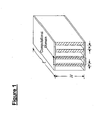
- Figure 1 depicts the geometric computational domain of a typical micro channel.
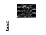
- Figure 2 is a photomicrograph of a cross section through a micro channel heat exchanger.
- Figure 3A shows dimensions (not to scale) of a representative micro channel configuration for a heat exchanger.
- Figure 3B is a chart comparing predicted and actual values of outlet temperatures of hot gas in a micro channel heat exchanger configured in accordance with the invention.
- Figure 4 is a cross section through a micro heat exchanger (not to scale) showing "hot” and “cold” sides.
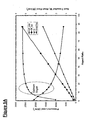
- Figure 5A , Figure 5B and Figure 5C are charts showing how, in differing manners with respect to the variations of the calculated curves of pressure loss, heat transfer rate and heat flux (in a given example for constant volume), plotted against channel aspect ratio, an approximation of the optimum range of aspect ratios for a specific situation is identified in accordance with the invention.
- Figure 5A an optimum region is identified; in Figure 5B , tangents of plotted curves are intersected; and in Figure 5C , the methodologies of Figure 5A and Figure 5B are adapted to the determination of a range on the aspect ratio axis of the plot.
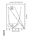
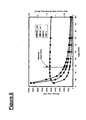
- Figure 6 is a chart showing the variation of the calculated parameters of pressure loss, heat transfer rate, and heat flux with channel aspect ratio in a situation where volume is variable and maximum aspect ratio is determined by the method of the invention.
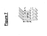
- Figure 7 illustrates a typical micro channel heat exchanger embodiment determined in accordance with the invention adapted to optimized compromise dimensions dictated by manufacturing requirements.
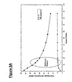
- Figure 8A and Figure 8B are plot of heat transfer and heat flux in a constant volume application where plotted curves are based on a hypothetical micro heat exchanger that is an order of magnitude greater than that shown in Figure 5A , Figure 5B , Figure 5C , and Figure 6 , a situation to which the method of the invention is similarly applicable.
- geometric parameters of the aspect ratio are determined for channels in a micro heat exchanger for gaseous fluids in which micro channels have a surface area density greater than 10000 m 2 /m 3 in the alternate situations a) where volume is constant, or b) where volume is variable and i) the given aspect ratio is less than or equal to 10 or ii) the given aspect ratio is more than 10.
- the separate methodologies of computational fluid dynamics and an analytical approach are combined under given constraints such as pumping power and space limitations and the variables optimized are channel width, aspect ratio and spacing.
- the optimal geometric parameters of a micro channel are obtained using plots of the performance curves of 1) pressure loss in the channel for the hot side; 2) pressure loss in the channel for the cold side; 3) heat flux; and 4) heat transfer rate -- against an axis corresponding to aspect ratio as a basis for a direct determination in the instance of constant volume, or further calculation in the instance of variable volume.
- the optimal geometric parameters of the channels of a micro heat exchanger are determined by combining the separate methodologies of computational fluid dynamics and an analytical approach. This results in an improvement over known calculation schemes such as described in V. K Samalam, Convective heat transfer in microchannels, J. Electronic Materials 18 (5) (1989) 611-617 .
- the analysis of the micro channel flow problem is reduced to a quasi two-dimensional differential equation that presents exact solutions analytically to determine optimal dimensions of micro channels under given constraints. Under given constraints such as pumping power and space limitations, the variables to be optimized are the channel width, aspect ratio and spacing.
- computational fluid dynamics (CFD) analysis is then used to determine the optimal aspect ratio of micro heat exchanger channels subject to given constraints. Based on the problem specification, the optimal geometric parameters of a micro channel are either directly obtained, based on the determined optimal aspect ratio, or are then calculated by the method described by Samalam.
- FIG. 1 The schematic model of the micro heat exchanger shown in Figure 1 consists of rectangular channels with hot and cold fluid flowing through alternate channels. The dimensions of the heat exchanger core are shown in the figure. The method described applies to co-flow and counter-flow configurations.
- the experimental device was a micro heat exchanger designed by the Pacific Northwest National Laboratories (PNNL).
- the material of the micro heat exchanger was steel.
- a cross-section through the heat exchanger is shown in Figure 2 .
- Figure 3 shows the dimensions (not to scale) of the micro channels of the heat exchanger.
- carbon dioxide with a total volumetric flow rate of 45 slpm, was used as cold gas and nitrogen, with a total volumetric flow rate of 44 slpm, was used as hot gas.
- Inlet temperatures of the gases for the three test conditions are shown in Table 1.
- constraints considered in the analyses were: 1) the maximum allowable pressure loss or pumping power; 2) the flow rate of hot and cold fluid; and 3) the parameters to be optimized were channel height, channel width and thickness of solid material between channels.
- the first step towards the dimensional / configuration optimization was to determine the thermal performance characteristics of the micro heat exchanger by conservative numerical equations. Two cases were considered: 1) the allowable volume of the heat exchanger as known based on design constraints; this volume would be kept constant; and 2) no limit is placed on the volume of the heat exchanger core; the volume would therefore be varied. For both cases, nitrogen is used as the hot fluid and carbon dioxide as the coolant.
- each micro channel of the heat exchanger was assigned a volume of 50 mm 3 . Assuming a fixed length of 40 mm for all channels, this resulted in a constant cross-sectional area of 1.25 mm 2 for each micro channel. Numerical simulations were performed by varying the aspect ratio of the micro channels in the range 1.25 ⁇ AR ⁇ 86.8 whilst maintaining a constant cross-sectional area, in this case, of 1.25 mm 2 . For a constant cross-sectional area of channel, the aspect ratio was varied by varying both the width, w c , and height, H , of the channels. Table 2 shows the inlet conditions for the aspect ratios considered. Inconel ® with a thickness of 0.1 mm was the micro channel material.
- Figure 5A , Figure 5B , and Figure 5C show the variation of heat flux, heat transfer rate and pressure drop in each channel with the aspect ratio, AR. It is clear from the plots shown in the figures that as the aspect ratio of the micro channel increases there is a rapid decrease in the heat flux coupled with a rapid increase in the pressure drop. Since the heat flux (and for that matter the heat transfer coefficient) and pressure loss have opposing trends there must be a balance between the two in choosing an optimal aspect ratio.
- the optimal aspect ratio lies in the optimal region which, in the various depictions shown in Figure 5A , Figure 5B , and Figure 5C , is the region marked by the intersection of the tangents at the points' maximum and minimum curvature on the heat transfer rate and heat flux curves.
- Table 3 shows examples of the micro channel dimensions based on aspect ratios within the marked optimum region. As mentioned earlier, these results were obtained based for fixed cross-sectional area and length ( i.e. , fixed volume) of micro channels.
- the volume of the micro heat exchanger was allowed to vary, but was kept within the limits that define a micro heat exchanger (i.e. , surface area density > 10000 m 2 /m 3 ).
- the flow rate of fluid was kept constant for the different volumes of micro heat exchangers analyzed.
- the length of the micro channels was fixed leaving the cross-sectional area as the variable.
- the aspect ratio was varied by changing the height of micro channels but keeping the width constant at 0.25 mm.
- the material of the micro channels was again Inconel ® with a thickness of 0.1 mm. Numerical simulations were performed by varying the aspect ratio of the micro channels in the range 5 ⁇ AR ⁇ 100.
- the operating conditions of the micro heat exchanger are shown in Table 4.
- Figure 6 shows the variation of heat flux, heat transfer rate and pressure drop in each channel with the aspect ratio, AR.
- aspect ratio of the micro channel increases there is an associated increase in the heat transfer rate up to a maximum value after which the heat transfer rate decreases.
- a higher aspect ratio leads to lower fluid velocity.
- the hydraulic diameter of the channel increases with aspect ratio. This increase in hydraulic diameter with aspect ratio combined with the attendant decrease in velocity leads to lower pressure drop in the channels as is shown in Figure 4 .
- the broken line in Figure 6 shows the (optimal) aspect ratio corresponding to the maximum heat transfer rate.
- the portion of Figure 6 to the left of the maximum is characterized by high heat flux as well as high pressure loss.
- the portion to the right of the optimal aspect ratio shows a very gradual decrease in heat transfer whereas the aspect ratio and hence the volume of micro heat exchanger increases. It follows operating in the region to the right of the maximum point would tremendously reduce the energy density of a micro heat exchanger.
- the optimal geometric parameters of the channels of a micro heat exchanger are determined when the volume of the micro heat exchanger is not fixed by design considerations.
- AR opt is an infinite number of pairs of channel height and width.
- the AR could therefore be viewed as a set populated by an infinite number of pairs of channel height and width.
- AR opt H 1 w 1 H 2 w 2 10.1 H n w n ...2015 .
- the design objective is to determine the pair ( H opt , w opt ) ⁇ AR opt that gives the best performance of the micro heat exchanger.
- AR opt ⁇ H 1 w 1 , H 2 w 2 , ...
- Table 5 demonstrates that a heat exchanger operating with two different fluids or with a same fluid will have different optimal dimensions for the channels transporting the hot and cold fluids. Whereas different optimal dimensions for a cold and a hot side are possible within micro heat exchangers of the type shown in Figure 7 , for the sake of simplicity of manufacture a compromise must be made in coming to the final dimensions in the case of the type of micro heat exchanger shown in Figure 4 .
- the performance of micro heat exchangers depends on the operating conditions and aspect ratio of the micro channels.
- the optimal dimensions of micro heat exchangers for a determined optimal aspect ratio may be calculated.
- the chart of Figure 8 shows a plot of heat transfer and heat flux in a constant volume application where plotted curves extend to a hypothetical order of magnitude greater, illustrating that the situation to which the method of the invention shown in Figure 5A , Figure 5B , Figure 5C , and Figure 6 is similarly adaptable to determine the range of preferred, and a specific, aspect ratio[s] for a micro channel device.
- the methods disclosed herein provide a system for manufacturing a micro channel heat exchanger in which pre-determined parameters of maximum allowable pressure loss and the flow rate of hot fluid and cold fluid on the opposite sides of the channels are established and one or more of the channel height, channel width and the thickness of a solid material between channels is/are optimized in accordance with the methods described herein.
- the optimized dimensions obtained in accordance with the methods and systems described above, are adapted to the requirements of a given manufacturing specification by compromising the calculated optimized dimensions to the requirements of a manufacturing design for the micro channel heat exchanger.
- a predetermined pumping power may be a determinant of the maximum allowable pressure loss.
- the determination of the maximum allowable pressure loss and the flow rate of hot fluid and cold fluid on the opposite sides of the channels may be a function of a predetermined length or other dimension established for the channels by manufacturing or design parameters; hence, other parameters will require adjustment when a given parameter is fixed by predetermined manufacturing requirements.
- the invention is directed as well to micro channel heat exchangers having channels with dimensions that are a result of a compromise of the optimum dimensions or ranges determined in accordance with the methods herein to adapt to the requirements of a predetermined manufacturing specification.
Landscapes
- Engineering & Computer Science (AREA)
- Physics & Mathematics (AREA)
- Thermal Sciences (AREA)
- Mechanical Engineering (AREA)
- General Engineering & Computer Science (AREA)
- Physical Or Chemical Processes And Apparatus (AREA)
- Heat-Exchange Devices With Radiators And Conduit Assemblies (AREA)
- Micromachines (AREA)
- Containers, Films, And Cooling For Superconductive Devices (AREA)
Claims (8)
- Verfahren zum Herstellen eines Mikrokanalwärmetauschers für gasförmige Fluide, in dem
der Wärmetauscher eine planare Anordnung von parallelen Mikrokanälen aufweist, wobei benachbarte Mikrokanäle dazu ausgelegt sind, zugehörige erste und zweite Fluidströmungen verschiedener Temperaturen für die Übertragung von Wärme von dem heißeren Fluid zu dem kälteren zu empfangen, und
die Mikrokanäle eine Oberflächendichte von mehr als 10000 m2/m3 aufweisen,
wobei in dem Verfahren ein Seitenverhältnis der Mikrokanäle in dem Wärmetauscher kennzeichnend dadurch bestimmt wird, dass
die thermische Leistungsfähigkeit des Wärmetauschers bestimmt wird, um Daten bezüglich eines Kanals zu erhalten, die der Wärmeübertragungsrate, Geschwindigkeit und Strömung entsprechen,
gegen eine dem Seitenverhältnis entsprechende Achse die Leistungsfähigkeitskurven von 1) dem Druckverlust in dem Kanal für die heiße Seite, 2) dem Druckverlust in dem Kanal für die kalte Seite, 3) dem Wärmefluss, und 4) der Wärmeübertragungsrate aufgetragen werden,
ein Bereich des Seitenverhältnisses auf Grundlage der aufgetragenen Kurven bestimmt wird, wobei diejenigen Punkte auf der Seitenverhältnis-Achse den Bereich eingrenzen, die den Achsenwerten des Maximums und des Minimums der Gradienten der Kurven für den Wärmefluss und die Wärmeübertragung entsprechen,
ein Seitenverhältnis für die Mikrokanäle aus dem bestimmten Bereich des Seitenverhältnisses ausgewählt wird, und
ein Wärmetauscher mit Mikrokanälen des ausgewählten Seitenverhältnisses hergestellt wird. - Verfahren zum Herstellen eines Mikrokanalwärmetauschers nach Anspruch 1, wobei die Abmessungen der Mikrokanäle dadurch bestimmt werden, dass:Nu auf Grundlage von Fluideigenschaften bestimmt wird,ein zulässiger Druckverlust ΔP festgelegt wird,eine Kanallänge ℓ für einen gegebenen Raum vorbestimmt wird,b aus der Gleichung


bestimmt wird,

bestimmt wird. - Verfahren nach Anspruch 1 oder 2, wobei die thermische Leistungsfähigkeit des Wärmetauschers gemäß den folgenden Formeln bestimmt wird:


und
- Verfahren nach Anspruch 3, wobei die Gültigkeit der bestimmten Abmessungen durch Anwendung der folgenden Formel verifiziert wird:

- Verfahren gemäß einem der vorstehenden Ansprüche, wobei die durch Optimierung hinsichtlich der Erfordernisse einer vorgegebenen Herstellungsspezifikation erhaltenen Abmessungen bestimmt werden, indem die optimierten Abmessungen mit den Erfordernissen eines Herstellungsdesigns für den Mikrokanalwärmetauscher harmonisiert werden.
- Verfahren nach Anspruch 5, wobei eine vorbestimmte Pumpleistung ein bestimmender Faktor des maximal zulässigen Druckverlusts ist.
- Verfahren nach Anspruch 5, wobei der maximal zulässige Druckverlust und die Strömungsrate des heißeren Fluids und des kälteren Fluids eine Funktion von einer oder mehreren vorbestimmten Abmessungen darstellt, die für die Kanäle aufgestellt wurden.
- Verfahren nach Anspruch 7, wobei die für die Kanäle aufgestellte vorbestimmte Abmessung die Länge ist.
Applications Claiming Priority (2)
| Application Number | Priority Date | Filing Date | Title |
|---|---|---|---|
| US10/666,263 US7059396B2 (en) | 2003-09-17 | 2003-09-17 | System for configuring the geometric parameters for a micro channel heat exchanger and micro channel heat exchangers configured thereby |
| PCT/US2004/030377 WO2005028980A2 (en) | 2003-09-17 | 2004-09-16 | System for configuring the geometric parameters for a micro channel heat exchanger |
Publications (3)
| Publication Number | Publication Date |
|---|---|
| EP1664652A2 EP1664652A2 (de) | 2006-06-07 |
| EP1664652A4 EP1664652A4 (de) | 2008-01-02 |
| EP1664652B1 true EP1664652B1 (de) | 2010-11-24 |
Family
ID=34274707
Family Applications (1)
| Application Number | Title | Priority Date | Filing Date |
|---|---|---|---|
| EP04788801A Expired - Lifetime EP1664652B1 (de) | 2003-09-17 | 2004-09-16 | System zur konfiguration der geometrischen parameter für einen mikrokanalwärmetauscher |
Country Status (6)
| Country | Link |
|---|---|
| US (1) | US7059396B2 (de) |
| EP (1) | EP1664652B1 (de) |
| JP (1) | JP2007506066A (de) |
| AT (1) | ATE489596T1 (de) |
| DE (1) | DE602004030260D1 (de) |
| WO (1) | WO2005028980A2 (de) |
Families Citing this family (19)
| Publication number | Priority date | Publication date | Assignee | Title |
|---|---|---|---|---|
| US8747805B2 (en) * | 2004-02-11 | 2014-06-10 | Velocys, Inc. | Process for conducting an equilibrium limited chemical reaction using microchannel technology |
| ES2270720B2 (es) * | 2005-08-26 | 2008-01-16 | Universidad Politecnica De Madrid | Procedimiento y aparato micro-cambiador de calor para la optimizacion de la transferencia de calor utilizando efectos oscilatorios no-estacionarios. |
| US20080115919A1 (en) * | 2006-11-16 | 2008-05-22 | Grant Allan Anderson | Radiator Tube with Angled Flow Passage |
| JP4777383B2 (ja) * | 2008-04-28 | 2011-09-21 | 株式会社日立製作所 | マイクロリアクタ |
| CA2879504A1 (en) | 2012-07-18 | 2014-01-23 | University Of Virginia Patent Foundation | Heat transfer device for high heat flux applications and related methods thereof |
| US10217692B2 (en) | 2012-07-18 | 2019-02-26 | University Of Virginia Patent Foundation | Heat transfer device for high heat flux applications and related methods thereof |
| US10296682B2 (en) * | 2013-02-07 | 2019-05-21 | Airbus Group India Private Limited | System and method for extracting relevant computational data for design analysis and validation |
| CN107690563B (zh) * | 2015-05-28 | 2021-02-09 | 林德股份公司 | 用于确定热交换器装置的状态的方法 |
| CN106783050B (zh) * | 2016-12-27 | 2018-08-07 | 全球能源互联网研究院有限公司 | 一种散热片及其设计方法及装置及变压器 |
| US20190162455A1 (en) * | 2017-11-29 | 2019-05-30 | Lennox Industries, Inc. | Microchannel heat exchanger |
| US11713931B2 (en) | 2019-05-02 | 2023-08-01 | Carrier Corporation | Multichannel evaporator distributor |
| JP7474577B2 (ja) | 2019-10-23 | 2024-04-25 | 株式会社Uacj | 伝熱二重管、伝熱二重管用内管及びその製造方法 |
| JP6823906B1 (ja) * | 2019-12-13 | 2021-02-03 | 株式会社Uacj | 熱交換器用二重管 |
| EP3910276A1 (de) * | 2020-05-13 | 2021-11-17 | Bluefors Oy | Wärmetauschermaterial und wärmetauscher für systeme zur kryogenen kühlung und ein system |
| CN111985048B (zh) * | 2020-08-03 | 2022-06-24 | 清华大学 | 超临界流体换热器通道结构的优化设计方法 |
| CN111928693B (zh) * | 2020-09-11 | 2024-09-24 | 上海新奥节能技术有限公司 | 一种一次表面式换热器芯体 |
| CN113490391B (zh) * | 2021-05-27 | 2024-06-21 | 合肥通用机械研究院有限公司 | 电子冷却用矩形微通道单元一维温度分布计算方法和系统 |
| JP2025501314A (ja) | 2022-01-04 | 2025-01-17 | ブルーエックスサーマル, インコーポレイテッド | 眼球領域熱伝達デバイスおよび関連付けられるシステム |
| CN116384289B (zh) * | 2023-06-05 | 2023-08-08 | 江西省水利科学院(江西省大坝安全管理中心、江西省水资源管理中心) | 一种通过计算流体动力学预测墩块式鱼道流量的方法 |
Family Cites Families (11)
| Publication number | Priority date | Publication date | Assignee | Title |
|---|---|---|---|---|
| US4516632A (en) * | 1982-08-31 | 1985-05-14 | The United States Of America As Represented By The United States Deparment Of Energy | Microchannel crossflow fluid heat exchanger and method for its fabrication |
| US5372188A (en) * | 1985-10-02 | 1994-12-13 | Modine Manufacturing Co. | Heat exchanger for a refrigerant system |
| US4894709A (en) * | 1988-03-09 | 1990-01-16 | Massachusetts Institute Of Technology | Forced-convection, liquid-cooled, microchannel heat sinks |
| US5771964A (en) * | 1996-04-19 | 1998-06-30 | Heatcraft Inc. | Heat exchanger with relatively flat fluid conduits |
| US6415860B1 (en) * | 2000-02-09 | 2002-07-09 | Board Of Supervisors Of Louisiana State University And Agricultural And Mechanical College | Crossflow micro heat exchanger |
| JP3821634B2 (ja) * | 2000-07-05 | 2006-09-13 | 株式会社デンソー | ワイパーブレードゴム用コーティング剤及びワイパーブレードゴム |
| US6939632B2 (en) * | 2001-08-06 | 2005-09-06 | Massachusetts Institute Of Technology | Thermally efficient micromachined device |
| US20030178188A1 (en) * | 2002-03-22 | 2003-09-25 | Coleman John W. | Micro-channel heat exchanger |
| US6622519B1 (en) * | 2002-08-15 | 2003-09-23 | Velocys, Inc. | Process for cooling a product in a heat exchanger employing microchannels for the flow of refrigerant and product |
| DE10246990A1 (de) * | 2002-10-02 | 2004-04-22 | Atotech Deutschland Gmbh | Mikrostrukturkühler und dessen Verwendung |
| US7422910B2 (en) * | 2003-10-27 | 2008-09-09 | Velocys | Manifold designs, and flow control in multichannel microchannel devices |
-
2003
- 2003-09-17 US US10/666,263 patent/US7059396B2/en not_active Expired - Fee Related
-
2004
- 2004-09-16 WO PCT/US2004/030377 patent/WO2005028980A2/en not_active Ceased
- 2004-09-16 JP JP2006527028A patent/JP2007506066A/ja active Pending
- 2004-09-16 EP EP04788801A patent/EP1664652B1/de not_active Expired - Lifetime
- 2004-09-16 AT AT04788801T patent/ATE489596T1/de not_active IP Right Cessation
- 2004-09-16 DE DE602004030260T patent/DE602004030260D1/de not_active Expired - Lifetime
Also Published As
| Publication number | Publication date |
|---|---|
| US7059396B2 (en) | 2006-06-13 |
| EP1664652A2 (de) | 2006-06-07 |
| WO2005028980A2 (en) | 2005-03-31 |
| DE602004030260D1 (de) | 2011-01-05 |
| JP2007506066A (ja) | 2007-03-15 |
| WO2005028980A3 (en) | 2005-09-09 |
| EP1664652A4 (de) | 2008-01-02 |
| ATE489596T1 (de) | 2010-12-15 |
| US20050056409A1 (en) | 2005-03-17 |
Similar Documents
| Publication | Publication Date | Title |
|---|---|---|
| EP1664652B1 (de) | System zur konfiguration der geometrischen parameter für einen mikrokanalwärmetauscher | |
| Garimella et al. | Transport in microchannels-a critical review | |
| Kewalramani et al. | Study of laminar single phase frictional factor and Nusselt number in In-line micro pin-fin heat sink for electronic cooling applications | |
| Khan et al. | A review on microchannel heat exchangers and potential applications | |
| Adachi et al. | Correlation between heat transfer and pressure drop in channels with periodically grooved parts | |
| Wei et al. | Experimental and numerical study of a stacked microchannel heat sink for liquid cooling of microelectronic devices | |
| Kandlikar | SINGLE-PHASE liquid flow in minichannels | |
| Hadad et al. | Performance analysis and shape optimization of an impingement microchannel cold plate | |
| Morini et al. | The role of the viscous dissipation in heated microchannels | |
| Rahbarshahlan et al. | Numerical simulation of fluid flow and heat transfer in microchannels with patterns of hydrophobic/hydrophilic walls | |
| Sekrani et al. | Conjugated heat transfer and entropy generation of Al2O3–water nanofluid flows over a heated wall-mounted obstacle | |
| Bessanane et al. | Numerical Study of the Temperature Effects on Heat Transfer Coefficient in Mini-Channel Pin-Fin Heat Sink. | |
| Duan et al. | Pressure drop of impingement air cooled plate fin heat sinks | |
| Al-Bakhit et al. | A hybrid approach for full numerical simulation of heat exchangers | |
| Khan et al. | Flow behavior and temperature distribution in micro-channels for constant wall heat flux | |
| Al-Neama | Serpentine minichannel liquid-cooled heat sinks for electronics cooling applications | |
| Maqableh et al. | Heat transfer characteristics of parallel and counter flow micro-channel heat exchangers with varying wall resistance | |
| Pandey | A Computational Fluid Dynamics Study of Fluid Flow and Heat Transfer in a Micro Channel | |
| Junianto et al. | A review of single-phase pressure drop characteristics microchannels with bends | |
| Glass et al. | An analytical model for the optimisation of metal foam for power electronics cooling | |
| EP4108458A1 (de) | Wellenförmiger wärmetauscherkern mit angrenzendem durchgang | |
| Marašević et al. | Optimization of compact heat exchangers | |
| Pandey et al. | Relative comparison of goodness factor for various channel shapes for counter flow microchannel heat exchanger | |
| Bessanane | Using Mini-Channel Configurations | |
| Negi et al. | Effect Of Dimensionless Number (KN And RE) On Performance Index Of Concentric Circular Micro Channel |
Legal Events
| Date | Code | Title | Description |
|---|---|---|---|
| PUAI | Public reference made under article 153(3) epc to a published international application that has entered the european phase |
Free format text: ORIGINAL CODE: 0009012 |
|
| 17P | Request for examination filed |
Effective date: 20060320 |
|
| AK | Designated contracting states |
Kind code of ref document: A2 Designated state(s): AT BE BG CH CY CZ DE DK EE ES FI FR GB GR HU IE IT LI LU MC NL PL PT RO SE SI SK TR |
|
| DAX | Request for extension of the european patent (deleted) | ||
| A4 | Supplementary search report drawn up and despatched |
Effective date: 20071205 |
|
| 17Q | First examination report despatched |
Effective date: 20090428 |
|
| GRAP | Despatch of communication of intention to grant a patent |
Free format text: ORIGINAL CODE: EPIDOSNIGR1 |
|
| RAP1 | Party data changed (applicant data changed or rights of an application transferred) |
Owner name: HONDA MOTOR CO., LTD. |
|
| GRAS | Grant fee paid |
Free format text: ORIGINAL CODE: EPIDOSNIGR3 |
|
| GRAA | (expected) grant |
Free format text: ORIGINAL CODE: 0009210 |
|
| AK | Designated contracting states |
Kind code of ref document: B1 Designated state(s): AT BE BG CH CY CZ DE DK EE ES FI FR GB GR HU IE IT LI LU MC NL PL PT RO SE SI SK TR |
|
| REG | Reference to a national code |
Ref country code: GB Ref legal event code: FG4D |
|
| REG | Reference to a national code |
Ref country code: CH Ref legal event code: EP |
|
| REG | Reference to a national code |
Ref country code: IE Ref legal event code: FG4D |
|
| REF | Corresponds to: |
Ref document number: 602004030260 Country of ref document: DE Date of ref document: 20110105 Kind code of ref document: P |
|
| REG | Reference to a national code |
Ref country code: NL Ref legal event code: VDEP Effective date: 20101124 |
|
| PG25 | Lapsed in a contracting state [announced via postgrant information from national office to epo] |
Ref country code: NL Free format text: LAPSE BECAUSE OF FAILURE TO SUBMIT A TRANSLATION OF THE DESCRIPTION OR TO PAY THE FEE WITHIN THE PRESCRIBED TIME-LIMIT Effective date: 20101124 Ref country code: SI Free format text: LAPSE BECAUSE OF FAILURE TO SUBMIT A TRANSLATION OF THE DESCRIPTION OR TO PAY THE FEE WITHIN THE PRESCRIBED TIME-LIMIT Effective date: 20101124 Ref country code: AT Free format text: LAPSE BECAUSE OF FAILURE TO SUBMIT A TRANSLATION OF THE DESCRIPTION OR TO PAY THE FEE WITHIN THE PRESCRIBED TIME-LIMIT Effective date: 20101124 Ref country code: PT Free format text: LAPSE BECAUSE OF FAILURE TO SUBMIT A TRANSLATION OF THE DESCRIPTION OR TO PAY THE FEE WITHIN THE PRESCRIBED TIME-LIMIT Effective date: 20110324 Ref country code: CY Free format text: LAPSE BECAUSE OF FAILURE TO SUBMIT A TRANSLATION OF THE DESCRIPTION OR TO PAY THE FEE WITHIN THE PRESCRIBED TIME-LIMIT Effective date: 20101124 Ref country code: BG Free format text: LAPSE BECAUSE OF FAILURE TO SUBMIT A TRANSLATION OF THE DESCRIPTION OR TO PAY THE FEE WITHIN THE PRESCRIBED TIME-LIMIT Effective date: 20110224 Ref country code: SE Free format text: LAPSE BECAUSE OF FAILURE TO SUBMIT A TRANSLATION OF THE DESCRIPTION OR TO PAY THE FEE WITHIN THE PRESCRIBED TIME-LIMIT Effective date: 20101124 Ref country code: FI Free format text: LAPSE BECAUSE OF FAILURE TO SUBMIT A TRANSLATION OF THE DESCRIPTION OR TO PAY THE FEE WITHIN THE PRESCRIBED TIME-LIMIT Effective date: 20101124 |
|
| PG25 | Lapsed in a contracting state [announced via postgrant information from national office to epo] |
Ref country code: GR Free format text: LAPSE BECAUSE OF FAILURE TO SUBMIT A TRANSLATION OF THE DESCRIPTION OR TO PAY THE FEE WITHIN THE PRESCRIBED TIME-LIMIT Effective date: 20110225 |
|
| PG25 | Lapsed in a contracting state [announced via postgrant information from national office to epo] |
Ref country code: ES Free format text: LAPSE BECAUSE OF FAILURE TO SUBMIT A TRANSLATION OF THE DESCRIPTION OR TO PAY THE FEE WITHIN THE PRESCRIBED TIME-LIMIT Effective date: 20110307 Ref country code: EE Free format text: LAPSE BECAUSE OF FAILURE TO SUBMIT A TRANSLATION OF THE DESCRIPTION OR TO PAY THE FEE WITHIN THE PRESCRIBED TIME-LIMIT Effective date: 20101124 Ref country code: CZ Free format text: LAPSE BECAUSE OF FAILURE TO SUBMIT A TRANSLATION OF THE DESCRIPTION OR TO PAY THE FEE WITHIN THE PRESCRIBED TIME-LIMIT Effective date: 20101124 Ref country code: BE Free format text: LAPSE BECAUSE OF FAILURE TO SUBMIT A TRANSLATION OF THE DESCRIPTION OR TO PAY THE FEE WITHIN THE PRESCRIBED TIME-LIMIT Effective date: 20101124 |
|
| PG25 | Lapsed in a contracting state [announced via postgrant information from national office to epo] |
Ref country code: SK Free format text: LAPSE BECAUSE OF FAILURE TO SUBMIT A TRANSLATION OF THE DESCRIPTION OR TO PAY THE FEE WITHIN THE PRESCRIBED TIME-LIMIT Effective date: 20101124 Ref country code: PL Free format text: LAPSE BECAUSE OF FAILURE TO SUBMIT A TRANSLATION OF THE DESCRIPTION OR TO PAY THE FEE WITHIN THE PRESCRIBED TIME-LIMIT Effective date: 20101124 Ref country code: RO Free format text: LAPSE BECAUSE OF FAILURE TO SUBMIT A TRANSLATION OF THE DESCRIPTION OR TO PAY THE FEE WITHIN THE PRESCRIBED TIME-LIMIT Effective date: 20101124 Ref country code: DK Free format text: LAPSE BECAUSE OF FAILURE TO SUBMIT A TRANSLATION OF THE DESCRIPTION OR TO PAY THE FEE WITHIN THE PRESCRIBED TIME-LIMIT Effective date: 20101124 |
|
| PLBE | No opposition filed within time limit |
Free format text: ORIGINAL CODE: 0009261 |
|
| STAA | Information on the status of an ep patent application or granted ep patent |
Free format text: STATUS: NO OPPOSITION FILED WITHIN TIME LIMIT |
|
| 26N | No opposition filed |
Effective date: 20110825 |
|
| PGFP | Annual fee paid to national office [announced via postgrant information from national office to epo] |
Ref country code: FR Payment date: 20111005 Year of fee payment: 8 Ref country code: GB Payment date: 20110916 Year of fee payment: 8 Ref country code: DE Payment date: 20110922 Year of fee payment: 8 |
|
| REG | Reference to a national code |
Ref country code: DE Ref legal event code: R097 Ref document number: 602004030260 Country of ref document: DE Effective date: 20110825 |
|
| PG25 | Lapsed in a contracting state [announced via postgrant information from national office to epo] |
Ref country code: IT Free format text: LAPSE BECAUSE OF FAILURE TO SUBMIT A TRANSLATION OF THE DESCRIPTION OR TO PAY THE FEE WITHIN THE PRESCRIBED TIME-LIMIT Effective date: 20101124 |
|
| PG25 | Lapsed in a contracting state [announced via postgrant information from national office to epo] |
Ref country code: MC Free format text: LAPSE BECAUSE OF NON-PAYMENT OF DUE FEES Effective date: 20110930 |
|
| REG | Reference to a national code |
Ref country code: CH Ref legal event code: PL |
|
| REG | Reference to a national code |
Ref country code: IE Ref legal event code: MM4A |
|
| PG25 | Lapsed in a contracting state [announced via postgrant information from national office to epo] |
Ref country code: CH Free format text: LAPSE BECAUSE OF NON-PAYMENT OF DUE FEES Effective date: 20110930 Ref country code: IE Free format text: LAPSE BECAUSE OF NON-PAYMENT OF DUE FEES Effective date: 20110916 Ref country code: LI Free format text: LAPSE BECAUSE OF NON-PAYMENT OF DUE FEES Effective date: 20110930 |
|
| GBPC | Gb: european patent ceased through non-payment of renewal fee |
Effective date: 20120916 |
|
| PG25 | Lapsed in a contracting state [announced via postgrant information from national office to epo] |
Ref country code: LU Free format text: LAPSE BECAUSE OF NON-PAYMENT OF DUE FEES Effective date: 20110916 |
|
| REG | Reference to a national code |
Ref country code: FR Ref legal event code: ST Effective date: 20130531 |
|
| PG25 | Lapsed in a contracting state [announced via postgrant information from national office to epo] |
Ref country code: GB Free format text: LAPSE BECAUSE OF NON-PAYMENT OF DUE FEES Effective date: 20120916 Ref country code: DE Free format text: LAPSE BECAUSE OF NON-PAYMENT OF DUE FEES Effective date: 20130403 |
|
| PG25 | Lapsed in a contracting state [announced via postgrant information from national office to epo] |
Ref country code: FR Free format text: LAPSE BECAUSE OF NON-PAYMENT OF DUE FEES Effective date: 20121001 |
|
| REG | Reference to a national code |
Ref country code: DE Ref legal event code: R119 Ref document number: 602004030260 Country of ref document: DE Effective date: 20130403 |
|
| PG25 | Lapsed in a contracting state [announced via postgrant information from national office to epo] |
Ref country code: TR Free format text: LAPSE BECAUSE OF FAILURE TO SUBMIT A TRANSLATION OF THE DESCRIPTION OR TO PAY THE FEE WITHIN THE PRESCRIBED TIME-LIMIT Effective date: 20101124 |
|
| PG25 | Lapsed in a contracting state [announced via postgrant information from national office to epo] |
Ref country code: HU Free format text: LAPSE BECAUSE OF FAILURE TO SUBMIT A TRANSLATION OF THE DESCRIPTION OR TO PAY THE FEE WITHIN THE PRESCRIBED TIME-LIMIT Effective date: 20101124 |