EP1663772B1 - Device for a mechanism for hatch cover sections of a ship - Google Patents
Device for a mechanism for hatch cover sections of a ship Download PDFInfo
- Publication number
- EP1663772B1 EP1663772B1 EP04775355A EP04775355A EP1663772B1 EP 1663772 B1 EP1663772 B1 EP 1663772B1 EP 04775355 A EP04775355 A EP 04775355A EP 04775355 A EP04775355 A EP 04775355A EP 1663772 B1 EP1663772 B1 EP 1663772B1
- Authority
- EP
- European Patent Office
- Prior art keywords
- attached
- aforementioned
- link
- arrangement
- accordance
- Prior art date
- Legal status (The legal status is an assumption and is not a legal conclusion. Google has not performed a legal analysis and makes no representation as to the accuracy of the status listed.)
- Expired - Fee Related
Links
Images


Classifications
-
- B—PERFORMING OPERATIONS; TRANSPORTING
- B63—SHIPS OR OTHER WATERBORNE VESSELS; RELATED EQUIPMENT
- B63B—SHIPS OR OTHER WATERBORNE VESSELS; EQUIPMENT FOR SHIPPING
- B63B19/00—Arrangements or adaptations of ports, doors, windows, port-holes, or other openings or covers
- B63B19/12—Hatches; Hatchways
- B63B19/14—Hatch covers
- B63B19/18—Hatch covers slidable
-
- B—PERFORMING OPERATIONS; TRANSPORTING
- B63—SHIPS OR OTHER WATERBORNE VESSELS; RELATED EQUIPMENT
- B63B—SHIPS OR OTHER WATERBORNE VESSELS; EQUIPMENT FOR SHIPPING
- B63B19/00—Arrangements or adaptations of ports, doors, windows, port-holes, or other openings or covers
- B63B19/12—Hatches; Hatchways
Definitions
- the present invention relates to an arrangement for a mechanism for the actuation of movable hatch cover sections of a ship respectively between the closed and open position and the open and closed position, which also comprises pivoting link elements movably attached to the respective hatch cover section that are capable of being influenced by force by means of an actuating cylinder hydraulic jack.
- Mechanisms for respectively opening and closing and locking hatch cover sections of the kind in question on board ships customarily consist of hydraulically actuated piston cylinder jacks or hydraulic motors and chains.
- the aforementioned hatch cover sections are caused in this way to be displaced on wheels to the desired positions along tracks intended for the purpose.
- Previously disclosed solutions for effecting the actual opening and closing and locking of the hatch cover sections comprise pivoting link arms which are connected together and actuated by a common jack in such a way, with the help of gripping devices, as to cause the hatch cover sections to be displaced respectively in a direction away from one another and in a direction towards one another for the purpose of opening and closing access to a lockable cargo space of the kind in question on board.
- a separate locking arrangement needs to be provided in this case.
- WO 02/090175 A1 representing the closest prior art as stated by the preamble of claim 1, for example, is a mechanism for actuating hatch cover sections on board a ship. Pairs of gear segments are utilized for this purpose, which are capable of being actuated by a jack causing them to pivot to intended positions. A special locking arrangement is required, however, in order to retain the hatch cover sections in place in the closed position, although the aforementioned locking arrangement is connected in such a way as to act between the jack and the gear segment.
- the principal object of the present invention is thus, in the first instance, to solve the aforementioned problems, among others, in a simple and effective fashion.
- pairs of pivoting link arms which are mounted on a common part of the ship, are each attached at their respective one end, preferably via claw connections, to a corresponding hatch cover section, and are attached at their respective other end to a divided link connection that is capable of being influenced by force by an aforementioned jack, and in that both link arms are attached to one another by means of a distance piece, whereby the application of force by means of the jack causes the link arms, by the forced interaction of the link connection parts, to pivot from the lowered and retracted locked position to the open position, in which position the respective attached hatch cover section is retained in the raised and parted position.
- This mechanism is to lift/operate and lower/operate the two hatch cover sections respectively from the closed to the open position and vice versa, when the hatch cover sections are simultaneously battened down and locked in their closed position.
- This new solution is a further development of previously disclosed solutions. Its characteristics compared with previously disclosed solutions are: the links are equivalent to the gear segments, although they require simpler manufacturing.
- the mechanism consists of a number of links and involves a saving in weight compared with gear rack segments. The entire mechanism can be built and installed as a unit without the need for adaptation between the deck and the frame.
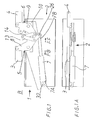
- a mechanism 2 for effecting the actuation of the movable hatch cover sections 3,4 of a ship respectively between the closed position A and the open position B and between the open position B and the closed position A which also comprises pivoting link elements 5,6 movably attached to the respective hatch cover sections 3,4 that are capable of being influenced by force by means of an actuating cylinder hydraulic jack 7, exhibits pivoting link arms 8,9 capable of interacting in pairs.
- Quite small parts of the respective intended hatch cover sections 3,4 are illustrated only schematically in the drawings, because such hatch cover sections normally cover the entire cargo width and longitudinal extent
- the aforementioned link arms 8,9 are supported on a common part 10 of the ship and are each attached at their respective one end 8A,9A to their corresponding hatch cover section 3,4, preferably via so-called claw connections.
- the link arms 8,9 are attached at their respective other end 8B,9B to a divided link connection 11.
- the aforementioned link connection 11 is influenced by force FF,FB by an aforementioned jack 7.
- Both link arms 8,9 are also attached to one another by means of a distance piece 12.
- the link arms 8, 9 are caused to pivot in this way, when force is applied by means of the jack 7, by the forced interaction of the link connection parts 13,14, from the lowered and retracted locked position C to the open position D.
- the respective attached hatch cover section 3,4 is retained in the raised and parted position B.
- the aforementioned divided link connections 11 are formed, as shown in the drawings, by pairs of interacting articulated arms 13,14, which are attached to one another in an articulated fashion at their respective one end 13A,14A via a common articulation 15. At a distance from the aforementioned common articulation 15, each of the two articulated arms 13,14 is attached in an articulated fashion to its corresponding link arm 5,6 via articulations 16,17.
- the aforementioned common articulation 15 is so arranged as to be capable of passing an imaginary straight line 18, which runs between the articulations 16,17 belonging to the respective link arm 8,9, at a given angle X in order to achieve so-called over-centre locking of the two links 8,9 in conjunction with passing the aforementioned imaginary line 18 and in order to permit the release of the locking in conjunction with the return of the aforementioned common articulation 15 past the aforementioned imaginary line 18.
- Both of the respective link arms 8,9 are pivotally mounted via articulations 19,31 and are supported by a common supporting part 10 on the ship.
- An aforementioned supporting part 10 is preferably formed by an elongated beam and/or plate 23, by which the mechanism 2 is supported as a unit 24, which can easily be transported and securely mounted rapidly and simply on the deck of the ship on the frame 21 of the opening alongside its frame top 22 without the need for complicated operations.
- One articulated arm 13 exhibits an angled pivot arm 25, which is directly or indirectly attached to an aforementioned jack 7.
- the aforementioned angled pivot arm 25 is so arranged as to extend at an obtuse angle Z from the remaining part 20 of the associated articulated arm 13, preferably between 100° and 140°.
- the articulation 16 between the aforementioned articulated arm 13 and one of the link arms 8 is situated for this purpose in the area of both pivot arms 20,25 of the aforementioned articulated arm 13, whereby the desired locking and unlocking of the mechanism 2 can be effected simply by respectively retracting and extending the jack 7.
- the two link arms 8,9 are also attached to one another via a rigid arm 12, which functions as a distance piece and is attached in an articulated fashion to fixing lugs 27,28 on the respective link arm 8,9 at its respective one end 8B,9A, as illustrated by way of example in Fig. 4 .
- the link arms 8,9 preferably exhibit triangular form with the articulations 29,30; 16,17 for the hatch cover sections 3,4 and the articulated arm 13 situated at its respective extremities.
- the link attachment parts 13,14 are double, with a pair of links each situated on its own side I, II of the two link arms 8,9.
- the aforementioned mechanism 2 is constructed as a common unit which is so arranged as to be capable of being installed in the position intended for its use simply by being attached to the ship by means of welding and/or bolted joints.
- the aforementioned jack 7 is supported by the aforementioned unit 24 and is pivotally attached at its one end 7A to a pivot 32 that is supported by the aforementioned plate 23 and/or beam 10 and is pivotally attached at its other opposing end 7B to a pivot 26.
Description
- The present invention relates to an arrangement for a mechanism for the actuation of movable hatch cover sections of a ship respectively between the closed and open position and the open and closed position, which also comprises pivoting link elements movably attached to the respective hatch cover section that are capable of being influenced by force by means of an actuating cylinder hydraulic jack.
- Mechanisms for respectively opening and closing and locking hatch cover sections of the kind in question on board ships customarily consist of hydraulically actuated piston cylinder jacks or hydraulic motors and chains. The aforementioned hatch cover sections are caused in this way to be displaced on wheels to the desired positions along tracks intended for the purpose.
- Previously disclosed solutions for effecting the actual opening and closing and locking of the hatch cover sections comprise pivoting link arms which are connected together and actuated by a common jack in such a way, with the help of gripping devices, as to cause the hatch cover sections to be displaced respectively in a direction away from one another and in a direction towards one another for the purpose of opening and closing access to a lockable cargo space of the kind in question on board. A separate locking arrangement needs to be provided in this case.
- Also previously disclosed through
WO 02/090175 A1 claim 1, for example, is a mechanism for actuating hatch cover sections on board a ship. Pairs of gear segments are utilized for this purpose, which are capable of being actuated by a jack causing them to pivot to intended positions. A special locking arrangement is required, however, in order to retain the hatch cover sections in place in the closed position, although the aforementioned locking arrangement is connected in such a way as to act between the jack and the gear segment. - Previously disclosed solutions require complicated manufacturing of constituent parts and do not permit simple installation as a common unit which does not need to be specially adapted between the deck and the frame in order for the mechanism to function reliably.
- The principal object of the present invention is thus, in the first instance, to solve the aforementioned problems, among others, in a simple and effective fashion.
- The aforementioned object is achieved by means of an arrangement in accordance with the present invention, which is characterized essentially in that pairs of pivoting link arms, which are mounted on a common part of the ship, are each attached at their respective one end, preferably via claw connections, to a corresponding hatch cover section, and are attached at their respective other end to a divided link connection that is capable of being influenced by force by an aforementioned jack, and in that both link arms are attached to one another by means of a distance piece, whereby the application of force by means of the jack causes the link arms, by the forced interaction of the link connection parts, to pivot from the lowered and retracted locked position to the open position, in which position the respective attached hatch cover section is retained in the raised and parted position.
- The invention is described below as a number of preferred illustrative embodiments, in conjunction with which reference is made to the accompanying drawings, in which:
-
Figures 1 and 1A show the arrangement with its associated mechanism with associated hatch cover sections held in the open position viewed respectively from the side and directly from above; -
Figures 2 and 2A show the mechanism in the open position with hatch cover sections held in the parted position at a distance from one another and viewed in perspective and from one end; -
Figures 3-3C show the mechanism in the closed and locked position with the hatch cover sections held together and viewed both in perspective from one end and from the side, and directly from above; and -
Figure 4 shows the function of the locking mechanism in detail in order to achieve self-locking. - The function of this mechanism is to lift/operate and lower/operate the two hatch cover sections respectively from the closed to the open position and vice versa, when the hatch cover sections are simultaneously battened down and locked in their closed position. This new solution is a further development of previously disclosed solutions. Its characteristics compared with previously disclosed solutions are: the links are equivalent to the gear segments, although they require simpler manufacturing. The mechanism consists of a number of links and involves a saving in weight compared with gear rack segments. The entire mechanism can be built and installed as a unit without the need for adaptation between the deck and the frame.
- An
arrangement 1 for amechanism 2 for effecting the actuation of the movablehatch cover sections pivoting link elements hatch cover sections hydraulic jack 7, exhibits pivotinglink arms hatch cover sections aforementioned link arms common part 10 of the ship and are each attached at their respective oneend 8A,9A to their correspondinghatch cover section link arms other end link connection 11. Theaforementioned link connection 11 is influenced by force FF,FB by anaforementioned jack 7. - Both
link arms distance piece 12. Thelink arms jack 7, by the forced interaction of thelink connection parts hatch cover section - The aforementioned divided
link connections 11 are formed, as shown in the drawings, by pairs of interacting articulatedarms end common articulation 15. At a distance from the aforementionedcommon articulation 15, each of the two articulatedarms corresponding link arm articulations - The aforementioned
common articulation 15 is so arranged as to be capable of passing an imaginarystraight line 18, which runs between thearticulations respective link arm links imaginary line 18 and in order to permit the release of the locking in conjunction with the return of the aforementionedcommon articulation 15 past the aforementionedimaginary line 18. - Both of the
respective link arms articulations part 10 on the ship. An aforementioned supportingpart 10 is preferably formed by an elongated beam and/orplate 23, by which themechanism 2 is supported as aunit 24, which can easily be transported and securely mounted rapidly and simply on the deck of the ship on theframe 21 of the opening alongside itsframe top 22 without the need for complicated operations. - One articulated
arm 13 exhibits anangled pivot arm 25, which is directly or indirectly attached to anaforementioned jack 7. The aforementionedangled pivot arm 25 is so arranged as to extend at an obtuse angle Z from theremaining part 20 of the associated articulatedarm 13, preferably between 100° and 140°. Thearticulation 16 between the aforementioned articulatedarm 13 and one of thelink arms 8 is situated for this purpose in the area of bothpivot arms arm 13, whereby the desired locking and unlocking of themechanism 2 can be effected simply by respectively retracting and extending thejack 7. - The two
link arms rigid arm 12, which functions as a distance piece and is attached in an articulated fashion to fixinglugs respective link arm end Fig. 4 . - The
link arms articulations hatch cover sections arm 13 situated at its respective extremities. - As can be clearly appreciated from the perspective views in
Figs. 2 and3 , thelink attachment parts link arms - In order to permit simple installation of the mechanism, the
aforementioned mechanism 2 is constructed as a common unit which is so arranged as to be capable of being installed in the position intended for its use simply by being attached to the ship by means of welding and/or bolted joints. Theaforementioned jack 7 is supported by theaforementioned unit 24 and is pivotally attached at its oneend 7A to apivot 32 that is supported by theaforementioned plate 23 and/orbeam 10 and is pivotally attached at its otheropposing end 7B to apivot 26. - The invention is naturally not restricted to the embodiments described above and illustrated in the accompanying drawings. Modifications are possible, in particular with regard to the nature of the various parts, or by the use of equivalent technology, but without departing from the area of protection afforded to the invention, as defined in the appended Claims.
Claims (10)
- Arrangement (1) for a mechanism (2) for the actuation of movable hatch cover sections (3,4) of a ship respectively between the closed and open position (A,B) and the open and closed position (B,A), which also comprises pivoting link elements (5,6) movably attached to the respective hatch cover section (3,4) that are capable of being influenced by force by means of an actuating cylinder hydraulic jack (7), characterized in that pairs of pivoting link arms (8,9), which are mounted on a common part (10) of the ship, are each attached at their respective one end (8A,9A), preferably via claw connections, to the corresponding hatch cover section (3,4), and are attached at their respective other end (8B,9B) to a divided link connection (11) that is capable of being influenced by force (FF,FB) by an aforementioned jack (7), and in that both link arms (8,9) are attached to one another by means of a distance piece (12), whereby the application of force by means of the jack causes the link arms (8,9), by the forced interaction of the link connection parts (13,14), to pivot from the lowered and retracted locked position (C) to the open position (D), in which position (D) the respective attached hatch cover section (3,4) is retained in the raised and parted position (B).
- Arrangement in accordance with claim 1, characterized in that divided link connections (11) are formed by pairs of interacting articulated arms (13,14), which are attached to one another in an articulated fashion at their respective one end (13A,14A) via a common articulation (15) and are each attached in an articulated fashion to their corresponding link arm (5,6) at a distance from the aforementioned common articulation (15).
- Arrangement in accordance with claim 2, characterized in that the aforementioned common articulation (15) is so arranged as to be capable of passing an imaginary straight line (18), which runs between the articulations (16,17) belonging to the respective link arm (8,9) in order to achieve so-called over-centre locking of the two links (8,9) in conjunction with passing the aforementioned imaginary line (18), and in order to permit the release of the locking in conjunction with the return of the aforementioned common articulation (15) past the aforementioned imaginary line (18).
- Arrangement in accordance with one or other of claims 2-3, characterized in that one articulated arm (13) exhibits an angled pivot arm (25), which is directly or indirectly attached to an aforementioned jack (7).
- Arrangement in accordance with claim 4, characterized in that the aforementioned angled pivot arm (25) extends at an obtuse angle (Z) from the remaining part (20) of the associated articulated arm (13), preferably between 100° and 140°.
- Arrangement in accordance with one or other of claims 4-5, characterized in that the aforementioned one articulated arm (13) is attached to the jack (7) via its angled pivot arm (25) .
- Arrangement in accordance with one or other of the foregoing claims, characterized in that the two link arms (8,9) are attached to one another via a rigid arm (12), which is attached in an articulated fashion to fixing lugs (27,28) on the respective link arm (8,9) at its respective one end (8B,9A).
- Arrangement in accordance with one or other of the foregoing claims, characterized in that the link arms (8,9) exhibit triangular form with the articulations (29,30; 16,17) for the hatch cover sections (3,4) and the articulated arm (13) situated in its respective tip areas.
- Arrangement in accordance with one or other of the foregoing claims, characterized in that the link connection parts (13,14) are double with a pair of links each situated on its own side (I,II) of the two link arms (8,9).
- Arrangement in accordance with one or other of the foregoing claims, characterized in that the aforementioned mechanism (2) is constructed as a common unit (24), which is so arranged as to be installed in the position intended for its use simply by being attached to the ship.
Applications Claiming Priority (2)
| Application Number | Priority Date | Filing Date | Title |
|---|---|---|---|
| SE0302466A SE524479C2 (en) | 2003-09-16 | 2003-09-16 | Boat hatch operating mechanism, has hatch sections connected to pivotable links and link arms operated by actuator cylinder |
| PCT/SE2004/001249 WO2005025977A1 (en) | 2003-09-16 | 2004-08-31 | Device for a mechanism for hatch cover sections of a ship |
Publications (2)
| Publication Number | Publication Date |
|---|---|
| EP1663772A1 EP1663772A1 (en) | 2006-06-07 |
| EP1663772B1 true EP1663772B1 (en) | 2009-06-10 |
Family
ID=29212473
Family Applications (1)
| Application Number | Title | Priority Date | Filing Date |
|---|---|---|---|
| EP04775355A Expired - Fee Related EP1663772B1 (en) | 2003-09-16 | 2004-08-31 | Device for a mechanism for hatch cover sections of a ship |
Country Status (7)
| Country | Link |
|---|---|
| EP (1) | EP1663772B1 (en) |
| JP (1) | JP4277043B2 (en) |
| KR (1) | KR101122320B1 (en) |
| CN (1) | CN100586790C (en) |
| NO (1) | NO335481B1 (en) |
| SE (1) | SE524479C2 (en) |
| WO (1) | WO2005025977A1 (en) |
Families Citing this family (7)
| Publication number | Priority date | Publication date | Assignee | Title |
|---|---|---|---|---|
| SE532596C2 (en) * | 2006-05-30 | 2010-03-02 | Tts Ships Equipment Ab | Device for the mechanism of operation of ships' movable locking sections |
| KR101138170B1 (en) * | 2009-09-03 | 2012-04-25 | 현대중공업 주식회사 | Up and Down Driving Apparatus of a Link Type for Hatch Cover |
| CN102050200B (en) * | 2009-10-29 | 2013-04-10 | 范茂荣 | Side-open type double-plate wave-proof door |
| PT2834144T (en) * | 2012-04-04 | 2016-10-24 | Beacon Finland Ltd Oy | An apparatus, an arrangement and a method for locking an underwater hatch or other removable structure |
| CN103061635B (en) * | 2013-01-18 | 2015-03-25 | 上海科得威船舶技术工程有限公司 | Hatch cover opening device |
| CN107842534A (en) * | 2017-09-29 | 2018-03-27 | 江苏威和海洋工程设备有限公司 | A kind of hatch board hydraulic jack group |
| CN111661244B (en) * | 2020-05-13 | 2021-07-23 | 上海海事大学 | Boats and ships safety cabin cover |
Family Cites Families (8)
| Publication number | Priority date | Publication date | Assignee | Title |
|---|---|---|---|---|
| US3272255A (en) * | 1954-04-12 | 1966-09-13 | Macgregor & Company Naval Arch | Power operating means for opening and closing hatch covers |
| US3330329A (en) * | 1965-09-13 | 1967-07-11 | David R Ligh | Hatch cover operating arrangement |
| US3335783A (en) * | 1965-10-22 | 1967-08-15 | David R Ligh | Actuator for folding closure |
| FR2529162B1 (en) * | 1982-06-25 | 1986-12-26 | Kone Oy | DEVICE FOR AUTOMATIC LOCKING OF A HATCH PANEL IN A CLOSED OR OPENED POSITION |
| SE468940B (en) * | 1989-03-17 | 1993-04-19 | Kvaerner Ships Equipment | Device pertaining to hinge arrangement for a hatch or other like sealing member |
| FI110178B (en) * | 1998-03-09 | 2002-12-13 | Macgregor Fin Oy | A cargo hatch swing device that covers the cargo hold of the cargo ship |
| JP4721506B2 (en) * | 2000-11-24 | 2011-07-13 | カヤバ システム マシナリー株式会社 | Ship hatch opening and closing structure |
| FI20010948A0 (en) * | 2001-05-07 | 2001-05-07 | Macgregor Fin Oy | Cargo hatch lifting device locking mechanism |
-
2003
- 2003-09-16 SE SE0302466A patent/SE524479C2/en not_active IP Right Cessation
- 2003-11-04 CN CN200310104763A patent/CN100586790C/en not_active Expired - Fee Related
-
2004
- 2004-08-31 EP EP04775355A patent/EP1663772B1/en not_active Expired - Fee Related
- 2004-08-31 JP JP2006526850A patent/JP4277043B2/en not_active Expired - Fee Related
- 2004-08-31 WO PCT/SE2004/001249 patent/WO2005025977A1/en active Application Filing
- 2004-08-31 KR KR1020067005289A patent/KR101122320B1/en active IP Right Grant
-
2006
- 2006-01-25 NO NO20060393A patent/NO335481B1/en not_active IP Right Cessation
Also Published As
| Publication number | Publication date |
|---|---|
| CN1597441A (en) | 2005-03-23 |
| KR20060076774A (en) | 2006-07-04 |
| CN100586790C (en) | 2010-02-03 |
| SE0302466L (en) | 2004-08-17 |
| WO2005025977A1 (en) | 2005-03-24 |
| SE0302466D0 (en) | 2003-09-16 |
| EP1663772A1 (en) | 2006-06-07 |
| SE524479C2 (en) | 2004-08-17 |
| JP2007505785A (en) | 2007-03-15 |
| JP4277043B2 (en) | 2009-06-10 |
| KR101122320B1 (en) | 2012-03-26 |
| NO20060393L (en) | 2006-06-07 |
| NO335481B1 (en) | 2014-12-15 |
Similar Documents
| Publication | Publication Date | Title |
|---|---|---|
| US5261779A (en) | Dual hydraulic, parallelogram arm wheelchair lift | |
| US6048021A (en) | Convertible top mechanism with powered rear row | |
| EP2352671B1 (en) | Landing gear bay door with double hook mechanism | |
| US4806062A (en) | Stowable lift for freight vehicles | |
| EP1663772B1 (en) | Device for a mechanism for hatch cover sections of a ship | |
| WO2011154527A1 (en) | Device for pivoting one or more front flaps of a track-guided vehicle and front-flap module | |
| FI120487B (en) | Cargo hatch access mechanism | |
| CA2045361A1 (en) | Truck box cover | |
| FI64096C (en) | ANORDNING FOER ATT VIKA IHOP OCH FAELLA UT EN ROERLIG LASTNINGSBRYGGA | |
| EP3737633A1 (en) | Hydraulic lift structure with vertical lifting movement for motor vehicles and similar vehicles | |
| CA3009921A1 (en) | Vertical hi-rail device | |
| EP1302388B1 (en) | Vehicle hood assembly for pedestrian protection | |
| US6273000B1 (en) | Rail switching system | |
| EP0837814B1 (en) | Device at a ship | |
| US5301626A (en) | Cargo hatch cover mechanism | |
| EP1263645A1 (en) | Device at a loading ramp on ships | |
| EP0847359A1 (en) | Arrangement for a sliding ship's door | |
| CN206202299U (en) | For the locking system of one or more headstock valve | |
| US20010047624A1 (en) | Seal for a pivoting ship door | |
| EP1062150A1 (en) | Rotating mechanism for cargo ship hatch cover | |
| WO2000075011A1 (en) | Guiding for a door | |
| EP2197779B1 (en) | Articulated mechanical arm | |
| EP0681535A1 (en) | Goods and weather protection device and foldable screen for screening off of a square surface | |
| AT400945B (en) | LOADING BRIDGE FOR A LOAD VEHICLE | |
| SU998221A1 (en) | Ship hatch cover |
Legal Events
| Date | Code | Title | Description |
|---|---|---|---|
| PUAI | Public reference made under article 153(3) epc to a published international application that has entered the european phase |
Free format text: ORIGINAL CODE: 0009012 |
|
| 17P | Request for examination filed |
Effective date: 20060303 |
|
| AK | Designated contracting states |
Kind code of ref document: A1 Designated state(s): GB GR IT |
|
| DAX | Request for extension of the european patent (deleted) | ||
| RBV | Designated contracting states (corrected) |
Designated state(s): GB GR IT |
|
| RIN1 | Information on inventor provided before grant (corrected) |
Inventor name: WEITER, ANNA |
|
| GRAP | Despatch of communication of intention to grant a patent |
Free format text: ORIGINAL CODE: EPIDOSNIGR1 |
|
| GRAS | Grant fee paid |
Free format text: ORIGINAL CODE: EPIDOSNIGR3 |
|
| GRAA | (expected) grant |
Free format text: ORIGINAL CODE: 0009210 |
|
| AK | Designated contracting states |
Kind code of ref document: B1 Designated state(s): GB GR IT |
|
| REG | Reference to a national code |
Ref country code: GB Ref legal event code: FG4D |
|
| REG | Reference to a national code |
Ref country code: GR Ref legal event code: EP Ref document number: 20090401901 Country of ref document: GR |
|
| PLBE | No opposition filed within time limit |
Free format text: ORIGINAL CODE: 0009261 |
|
| STAA | Information on the status of an ep patent application or granted ep patent |
Free format text: STATUS: NO OPPOSITION FILED WITHIN TIME LIMIT |
|
| 26N | No opposition filed |
Effective date: 20100311 |
|
| GBPC | Gb: european patent ceased through non-payment of renewal fee |
Effective date: 20090910 |
|
| PG25 | Lapsed in a contracting state [announced via postgrant information from national office to epo] |
Ref country code: GB Free format text: LAPSE BECAUSE OF NON-PAYMENT OF DUE FEES Effective date: 20090910 |
|
| PG25 | Lapsed in a contracting state [announced via postgrant information from national office to epo] |
Ref country code: IT Free format text: LAPSE BECAUSE OF FAILURE TO SUBMIT A TRANSLATION OF THE DESCRIPTION OR TO PAY THE FEE WITHIN THE PRESCRIBED TIME-LIMIT Effective date: 20090610 |
|
| PGFP | Annual fee paid to national office [announced via postgrant information from national office to epo] |
Ref country code: GR Payment date: 20140828 Year of fee payment: 11 |
|
| PG25 | Lapsed in a contracting state [announced via postgrant information from national office to epo] |
Ref country code: GR Free format text: LAPSE BECAUSE OF NON-PAYMENT OF DUE FEES Effective date: 20160303 |
|
| REG | Reference to a national code |
Ref country code: GR Ref legal event code: ML Ref document number: 20090401901 Country of ref document: GR Effective date: 20160303 |