EP1663771B1 - Molded plastic gangway - Google Patents
Molded plastic gangway Download PDFInfo
- Publication number
- EP1663771B1 EP1663771B1 EP04784501.1A EP04784501A EP1663771B1 EP 1663771 B1 EP1663771 B1 EP 1663771B1 EP 04784501 A EP04784501 A EP 04784501A EP 1663771 B1 EP1663771 B1 EP 1663771B1
- Authority
- EP
- European Patent Office
- Prior art keywords
- gangway
- section
- grooves
- recesses
- groove
- Prior art date
- Legal status (The legal status is an assumption and is not a legal conclusion. Google has not performed a legal analysis and makes no representation as to the accuracy of the status listed.)
- Expired - Lifetime
Links
- 239000002991 molded plastic Substances 0.000 title 1
- 210000005069 ears Anatomy 0.000 claims description 12
- 230000003014 reinforcing effect Effects 0.000 claims description 3
- XLYOFNOQVPJJNP-UHFFFAOYSA-N water Substances O XLYOFNOQVPJJNP-UHFFFAOYSA-N 0.000 description 5
- 239000000463 material Substances 0.000 description 4
- 238000010276 construction Methods 0.000 description 2
- 239000006260 foam Substances 0.000 description 2
- 230000007704 transition Effects 0.000 description 2
- 230000006978 adaptation Effects 0.000 description 1
- XAGFODPZIPBFFR-UHFFFAOYSA-N aluminium Chemical compound [Al] XAGFODPZIPBFFR-UHFFFAOYSA-N 0.000 description 1
- 229910052782 aluminium Inorganic materials 0.000 description 1
- JEIPFZHSYJVQDO-UHFFFAOYSA-N iron(III) oxide Inorganic materials O=[Fe]O[Fe]=O JEIPFZHSYJVQDO-UHFFFAOYSA-N 0.000 description 1
- 230000013011 mating Effects 0.000 description 1
- 238000000034 method Methods 0.000 description 1
- 230000002035 prolonged effect Effects 0.000 description 1
Images


Classifications
-
- B—PERFORMING OPERATIONS; TRANSPORTING
- B63—SHIPS OR OTHER WATERBORNE VESSELS; RELATED EQUIPMENT
- B63B—SHIPS OR OTHER WATERBORNE VESSELS; EQUIPMENT FOR SHIPPING
- B63B27/00—Arrangement of ship-based loading or unloading equipment for cargo or passengers
- B63B27/14—Arrangement of ship-based loading or unloading equipment for cargo or passengers of ramps, gangways or outboard ladders ; Pilot lifts
-
- E—FIXED CONSTRUCTIONS
- E01—CONSTRUCTION OF ROADS, RAILWAYS, OR BRIDGES
- E01D—CONSTRUCTION OF BRIDGES, ELEVATED ROADWAYS OR VIADUCTS; ASSEMBLY OF BRIDGES
- E01D15/00—Movable or portable bridges; Floating bridges
- E01D15/24—Bridges or similar structures, based on land or on a fixed structure and designed to give access to ships or other floating structures
-
- E—FIXED CONSTRUCTIONS
- E02—HYDRAULIC ENGINEERING; FOUNDATIONS; SOIL SHIFTING
- E02B—HYDRAULIC ENGINEERING
- E02B3/00—Engineering works in connection with control or use of streams, rivers, coasts, or other marine sites; Sealings or joints for engineering works in general
- E02B3/04—Structures or apparatus for, or methods of, protecting banks, coasts, or harbours
- E02B3/06—Moles; Piers; Quays; Quay walls; Groynes; Breakwaters ; Wave dissipating walls; Quay equipment
- E02B3/062—Constructions floating in operational condition, e.g. breakwaters or wave dissipating walls
- E02B3/064—Floating landing-stages
-
- B—PERFORMING OPERATIONS; TRANSPORTING
- B63—SHIPS OR OTHER WATERBORNE VESSELS; RELATED EQUIPMENT
- B63B—SHIPS OR OTHER WATERBORNE VESSELS; EQUIPMENT FOR SHIPPING
- B63B2231/00—Material used for some parts or elements, or for particular purposes
- B63B2231/40—Synthetic materials
-
- E—FIXED CONSTRUCTIONS
- E01—CONSTRUCTION OF ROADS, RAILWAYS, OR BRIDGES
- E01D—CONSTRUCTION OF BRIDGES, ELEVATED ROADWAYS OR VIADUCTS; ASSEMBLY OF BRIDGES
- E01D2101/00—Material constitution of bridges
- E01D2101/40—Plastics
Definitions
- This invention relates to a molded gangway section used for example with docks, piers, and the like, and in particular, to a gangway which is molded from plastic.
- Gangways have long been used to provide access between shore and docks, or between docks and boats.
- Gangways that are currently used are often one piece units that are assembled on-site. These gangways are time consuming and difficult to assemble. Additionally, the gangways are difficult to secure, for example, to the dock, a shore abutment, etc, Further, once assembled, the gangways are difficult to remove, for example, for storage in winter or for repair.
- the molded gangway section of the invention is characterized by the features claimed in the characterizing part of claim 1,
- a molded gangway section characterized in that the lower surface comprises a plurality of recesses, the recesses being defined by a side wall extending from the lower surface towards the upper surface and a recess ceiling , the recess ceiling comprising a plurality of grooves in the ceiling which extend toward the gangway upper surface, the recess ceiling grooves are adjacent the upper surface and the recess ceiling grooves contact the upper surface or are spaced slightly from the upper surface.
- the molded gangway section of the present invention comprises an upper surface, side surfaces, and a lower surface, which, in combination define a volume.
- the volume is hollow (i. e. , empty), but could be filled, for example, with foam or other buoyant materials.
- the gangway sides extend above the top surface and define rails.
- the top surface includes spaced apart, generally parallel grooves, which extend across the top surface from one side to the other. Additionally, a groove extends along the junction between the upper surface and at least one of the side walls.
- the lower surface comprises a plurality of recesses which are defined by a side wall extending from the lower surface towards the upper surface and a recess ceiling.
- a plurality of grooves which extend generally parallel to the upper surface grooves, are formed in the recess ceiling.
- the recesses are formed in at least three columns - there being two side columns and one center column. There can also be two or more center columns.
- the columns are made of rows of recesses, such that the recesses define an array or recesses, such as a 3x3 or 4x3 array of recesses.
- a trough is formed in the lower surface between the outer and center columns of recesses. Additional surface grooves are formed in the bottom surface between the rows of recesses. A surface groove is also formed in the gangway bottom surface between the outer columns of recesses and the sides of the gangway.
- the lower surface also includes a connecting surface at opposite ends of the gangway. Preferably, the connecting surface is divided into three areas which are aligned with the columns of recesses.
- the recess ceiling grooves are adjacent, and preferably, in contact with, the lower side of the upper surface.
- the recess ceiling grooves preferably include two types of grooves - the first grooves are positioned to be under the upper surface grooves and the second grooves are positioned between the upper surface grooves.
- the first grooves are formed by a wall of substantially constant width.
- the second grooves, of at least the outer column of recesses, have a first portion of a first thickness and a second portion of a second thickness, thicker than the first portion.
- Two or more gangway sections can be connected together to form a gangway.
- Gangway sections can be connected using a reinforcing member or truss which is received in the gangway bottom surface trough.
- the truss is sized to extend across the junction between adjacent gangway sections.
- the truss is secured to the gangway sections by fasteners which extend through the gangway section upper surface and into the truss.
- the gangway sections can also be connected by use of connector plates which span the junction between two adjacent gangways.
- the connecting plates which are sized to span the junction between adjacent gangway sections, are secured to the connecting surface on the gangway section bottom surface.
- two connecting plates are used - one on each of the outer connecting surface areas.
- the gangway sections can be connected using either of the two methods independently, but, are preferably connected together using the trusses and the connecting plates in combination.
- the gangway connecting surface is also used to connect the gangway to shore abutments, piers, docks, etc.
- the gangway section includes a hinge member mountable to the connection surface.
- hinge members are mounted in all three areas of the connection surface.
- the hinge members includes pin sleeves which, when the hinge member is mounted to the gangway section, extend outwardly from the end of the gangway section.
- the gangway section can be mounted to a shore abutment or dock using a bracket.
- the bracket includes pin sleeves positioned to be aligned with the pin sleeves of the hinge member.
- a hinge pin extends through the pin sleeves of the hinge member and the bracket to hingedly connect the gangway to the shore abutment bracket, and hence, the shore abutment.
- the gangway section can also be provided with a roller assembly and/or a ramp.
- the ramp includes a sloped upper surface, a back surface, and ears extending from the back surface.
- the ears include openings therein which are aligned with the hinge member pin sleeves when the ramp is adjacent the gangway section.
- a hinge pin which extends through the hinge member pin sleeve and the ramp ears to hingedly connect the ramp to the gangway.
- the roller assembly includes opposed mounting members mountable to lower surfaces of the sides of the gangway and a roller extending between the mounting members. The roller is vertically spaced from the connecting surface and the mounting brackets are horizontally spaced from the connecting surface. Thus, the roller assembly can be mounted to the gangway along with the ramp.
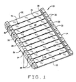
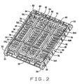
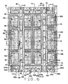
- FIGS 1 and 2 An illustrative embodiment of a gangway section 10 of the present invention is seen generally in FIGS 1 and 2 .
- a complete gangway can be formed from a single gangway section 10, or two or more of the gangway sections 10 can be connected together, as will be described below, to form a gangway of a desired length.
- the gangway section 10 is quadrilateral in shape having two opposed and generally parallel ends 12 and two opposed and generally parallel sides 14. In a preferred embodiment, the gangway section is about 6' long and about 4' wide. These dimension, of course, can be changed if desired.
- the gangway section 10 includes an upper surface 16 having a top side 18 upon which a person walks and a bottom side 20; a bottom surface 22 spaced from the upper surface; and opposed sides 24 extending between the upper surface 16 and the bottom surface 22.
- the sides 24 are generally rectangular in cross-section, as seen best in FIGS. 7 and 10 .
- the sides 24 include an outer wall 26, an inner wall 28, a top wall 30 and a bottom wall 32.
- the side bottom wall 32 is approximately level with the gangway section bottom surface 22.
- the side top wall 30, however, is spaced above the gangway section upper surface 16.
- the sides 24 define rails which extend the length of the gangway section.
- the sides 24 are generally pentagonal in side elevation.
- the sides 24 include grooves 34 on the side top wall 30 which extend between the outer and inner walls 26 and 28, respectively, and grooves 36 on the outer side walls 26 which extend between the side top and bottom walls 30 and 32, respectively.
- the sides 24 can be divided into end sections which have the side wall grooves 36 and a central section which does not have the grooves 36. In the end sections, with the grooves 36, there are side wall grooves 36 which intersect with the top wall grooves 34 and side wall grooves 36 between the position of the top wall grooves 34.
- the upper surface is provided with channels 38 at the junction of the side inner wall 28 and the gangway upper surface 16.
- Transverse channels 40 extend across the width of the gangway upper surface 16 between the channels 38, and intersect with the channels 38.
- the channels 40 are co-linear with the side top wall channels 34.
- the channels 38 are deeper than the channels 40.
- the channels 40 empty into the channels 38.
- the channels 40 define a waterway to direct water off the upper surface of the gangway. The channels 40 facilitate movement of any water on the gangway upper surface to the channels 38.
- the bottom surface is provided with a plurality of recesses 50L, 50R, 52L, 52R, 54L, 54R, 56 and 58.
- the recesses 50L and 50R are mirror images of each other, as are recesses 52L and 52R and recesses 54L and 54R.
- the recesses 50L, 50R, 52L, 52R, 54L, and 54R are side recesses and are substantially similar to each other, hence, only one of the recesses will be described below.
- the recesses 56 and 58 are inner recesses and differ from the side recesses in only one respect, which will be pointed out below. As can be seen in FIG.
- the recesses are all generally quadrilateral in plan and are arranged in 3x4 array.
- the end recesses 50L,R, 54L,R, and 56 are shorter than the center recesses 52R,L and 58.
- the side recesses are separated from the inner recesses by troughs 60 defined by trough side walls 62 and a trough upper wall 64 which is spaced from the bottom side 20 of the gangway upper surface 16.
- a plurality of spaced apart grooves 66 extend across the troughs 60.
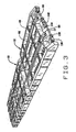
- the troughs 60 are sized and shaped to receive trusses 68 ( FIG. 3 ) to connect to gangway sections 10 together, as will be described below.
- a plurality of screw holes 70 extend through the gangway upper surface 16 and into the channel 60 to accept fasteners 72 (such as bolts or screws) to secure the trusses 68 in the channels 60.
- Grooves 74 are formed in the gangway bottom surface 22 between the inner end recesses 56 and the inner central recesses by grooves 74. Additionally, a groove 76 is formed in the bottom surface 22 between the two rows of inner recesses. Similarly, grooves 78 are formed in the gangway bottom surface 22 between the side end recesses 50R,L and 54R,L. Lastly, an elongate groove 80 extends alongside of the side recesses in the gangway bottom surface 16 (which at that point also forms the bottom wall 32 of the sides 24).
- the recesses are all generally similar in configuration.
- the recesses include end walls 82 which are generally parallel to the ends 12 of the gangway section 10, side walls 84 which are generally parallel to the sides 24 of the gangway, and ceilings 86 which span between the opposed end walls 82 and opposed side walls 84.
- the outer side wall of the recesses is also the inner side wall 28 of the gangway side 24.
- the recesses all have a generally quadrilateral shape. However, the shape of the recesses could be changed, and the recesses could be circular, triangular, trapezoidal, or any other desired shape in plan view.
- the recess ceiling 86 includes a ceiling surface 88 with a series of spaced apart, generally perpendicular grooves 90 extending between the recess sidewalls 84.
- the grooves 90 give the recess ceiling 86 a generally crenellated appearance in cross-section, as seen in FIGS. 8 and 11-13 .
- the ceiling surface 88 is spaced from the bottom side 20 of the gangway upper surface 18, and the grooves 90 have a peak which is adjacent the bottom side 20 of the gangway upper surface 18.
- the groove peaks contact, or are spaced only slightly from, the gangway upper surface bottom side 20.
- Grooves 90a are beneath the gangway upper surface grooves 40 and grooves 90b are spaced between the gangway upper surface grooves 40.
- the contact between the grooves 90b and the bottom 20 of the upper surface is shown in FIG. 10 , where, the top of the groove 90a is essentially merged into the bottom of the gangway upper section.
- the bottom (or exposed) surface of the grooves 90a and 90b are substantially identical.
- the inner or upper surface of the walls which form the grooves 90a and 90b are varied slightly. While these inner surfaces are both generally trapezoidal in shape, the grooves 90a generally come to a point at their peaks where they are closest to the gangway upper surface.
- the grooves 90b have a generally flat peak area where the grooves 90b are closest to the upper surface grooves 40.
- the grooves 90a extend upwardly to contact (or nearly contact) the bottom of the gangway upper surface and the grooves 90b extend upwardly to contact (or nearly contact) the bottom of the upper surface grooves 40, the grooves 90a are deeper than the grooves 90b.
- the grooves 90a and 90b are formed by a groove wall that has a generally constant thickness.
- the grooves 90a are formed in two parts or portions.
- the grooves 90a include an inner portion having a wall thickness substantially similar to the wall thickness of the groove 90b.
- the grooves 90a also include an outer portion which, as seen in FIG. 12 , has an increased wall thickness, especially along the top of the groove.
- This second outer portion of the groove 90a extends from the recess outer side wall 84 a distance equal to about 1 ⁇ 4 to about ? the length of the groove.
- the grooves are less deep.
- the depth of the grooves 90a in the second portion is about as deep as the grooves 90b.
- the groove 90a is thickened in the second portion such that its depth in this second portion is approximately equal to the depth of the grooves 90b.
- the grooves 90a of the inner recesses 56 and 58 do not include any such thickened area.
- the recesses do not extend the full length of the gangway section 10.
- the gangway section 10 is provided with attachment areas 100a,b at opposite ends of the gangway section in the bottom surface 22 of the gangway section 10.
- the gangway sections 100a,b are all recessed relative to the gangway bottom surface 22 and have connection surfaces 102a,b which are substantially parallel with the cavity ceiling surfaces 88.
- the attachment areas 100a are co-linear with the side recesses 50R,L, 52R,L and 54R,L and have a width substantially equal to the width of the side recesses.
- the attachment areas 100b are at the ends of the inner recesses 56 and 58 and have a width substantially equal to the combined width of the two rows of inner recesses.
- the attachment areas 100a,b each include a groove 104a,b which extends generally perpendicular to the gangway sides 24 across the approximate center of the attachment surfaces 102a,b.
- a circumferential groove 106 extends around three sides of the attachment surfaces 102a,b, such that the grooves 106 have a generally U-shaped appearance in plan view.
- the attachment surfaces 102b each include grooves 108 which extend generally perpendicularly to the grooves 104b and effectively divide the attachment surfaces 102b into thirds. Each third of the attachment surface 102b is approximately equal in width to the attachment surfaces 102a.
- the attachment surfaces 102a,b are provided with screw holes 110.
- each attachment surface is provided with three screw holes 110 formed in a generally triangular pattern. Two screw holes are provided between the end of the gangway section and the groove 104a,b and one hole is provided between the groove 104a,b and the U-shaped groove 106.
- the surfaces which define the gangway section, as described above, in combination, define a chamber C1. Additionally, the surfaces which define the sides 24 define a second chamber C2 which, preferably, is separate and distinct from the chamber C1.
- the chambers C1 and C2 are preferably hollow.
- the gangway section is buoyant.
- One or all of the chambers could be filled with a buoyant material, such as foam, to increase buoyancy of the gangway section, if necessary.
- connection plate 120 is provided for the outer attachment areas 100a.
- the plates 120 have a length approximately equal to the combined length of the attachment surfaces 102a when two gangway sections are in abutting relationship, as seen in FIG. 3 . Hence, the plates 120 will span across the two gangway sections 10.
- the plates 120 are provided with screw holes 122 which are arranged in a pattern such that the screw holes 122 will be aligned with the screw holes 110 of the attachment surfaces 102a. Screws 124 (preferably with washers 126) are passed through the connection plate screw holes 122 and into the attachment surface screw holes 110 in order to connect two gangway sections together.
- connection plates are made from a material, such as aluminum, which will not rust upon prolonged exposure to water.
- the plates could also be made of other materials.
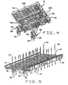
- trusses 68 FIGS. 3 and 5 .
- the trusses 68 are received in the bottom surface troughs 60.
- Fasteners 72 are passed through the holes 70 in the gangway upper surface and through the trusses 68 to secure the trusses 68 to the gangway section.
- the fasteners are bolts, which are passed through the gangway section and trusses and receive nuts to hold the trusses to the gangway section.
- the trusses can be provided with bolt holes, or bolt holes can be drilled through the trusses on site.
- two trusses are provided, which, as described above, are positioned between the three rows of recesses.
- the gangway bottom section could be modified to use a single truss extending, for example, along the center of the gangway section.
- the trusses 68 are provided to increase stability of the gangway. Hence, trusses 68 extend the full length of the gangway. Thus, if the gangway comprise three sections, the trusses will extend for three sections (or 18' for three 6' long sections). If the gangway comprises only two section, then the trusses will have an overall length of 12'.
- the trusses can each be comprised of a single long truss, or can be made of truss sections which are secured to the gangway sections. If truss sections are used, the junctions between adjacent truss sections is positioned away from the junction between adjacent gangway sections, and is preferably positioned near the center of the gangway sections.
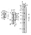
- hinges 130 and 132 can be mounted to the attachment surfaces 102a and 102b, respectively, to enable the gangway section 10 to be mounted to shore abutments, decks, etc.
- the hinges 130 each include a mounting plate 134 and pin sleeves 136.
- the hinge mounting plates 134 have a width substantially equal to the width of the respective attachment surface 102a,b and holes 138 positioned to be aligned at least with the two end holes 110 on the gangway attachment surface. Screws 140 are used to secure the hinge plates to the attachment surfaces 102a,b.
- the hinges 130 are generally L-shaped and include a leg 142 at the end of the mounting plate 134 to which the hinge pin sleeves 136 are mounted..
- the hinge leg 142 overlies the end surface of the gangway section 10.
- the hinge pin sleeves 136 extend outwardly from the gangway end surface.
- a mating hinge plate 152 is mounted to the shore abutment 150.
- the hinge plate 152 is shown to be generally a right angle member which overlies a corner of the shore abutment 150 and is connected to the shore abutment by screws, bolts, or other fasteners which extend through both legs of the angle member.
- Pin sleeves 154 are positioned on the generally vertical leg of the hinge plate 152 and are positioned to be offset from the pin sleeves 136 of the hinge plates 130 mounted to the gangway attachment surface.
- a hinge pin 156 passes through the pin sleeves of the opposing hinge plates to hingedly connect the gangway section 10 to the shore abutment 150.
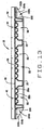
- the gangway 10 is shown connected to a floating dock section 160.
- the dock section 160 is preferably one such as US Pat. No. 5280155 , which is incorporated herein by reference.
- the dock section 160 is provided with hardware connectors 162 having threaded shafts 164 extending outwardly therefrom.
- a hinge plate or bracket 166 is mounted to a side surface of the dock section 160 using the hardware connectors 162.
- the bracket 166 is generally U-shaped in configuration, and includes holes 168 in its legs and top cross member. The holes 168 are positioned to be aligned with the connector shafts 164, and the shafts 164 extend through the bracket holes 168 to receive nuts 170 to secure the bracket 166 to the dock section 160.
- the bracket additionally includes pin sleeves 172 positioned along the cross-member of the bracket 166.
- the pin sleeves are positioned to be offset from the pin sleeves of the gangway hinge.
- a hinge pin 174 is passed through the respective pin sleeves to hingedly connect the gangway section 10 to the dock section 160.
- the bracket 166 is sized and positioned on the dock section 160 such that the upper surface of the gangway and the upper surface of the dock 160 will be substantially co-planar when the gangway is connected to the dock section.
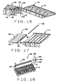
- FIG. 17 shows the connection of a ramp or transition plate 180 to the gangway 10.
- the ramp 180 is generally triangular in side elevation and has a top surface 182, side surfaces 184, and a back surface 186.
- a plurality of ears 188 extend from the back surface 186 and have openings 190 through which a hinge pin 192 can extend.
- the hinge pin 192 extends through the pin sleeves of the gangway hinges and through the ears of the ramp.
- the ramp ears 188 are arranged in pairs, the ears of each pair being spaced apart a distance slightly greater than the length of the gangway hinge pin sleeves. Hence, the ramp ears sandwich the gangway hinge pin sleeves. Additionally, the number of pairs of ears corresponds to the number of pin sleeves on the gangway hinge.
- the gangway can pivot about the hinge pin as the dock, pier, etc. to which the gangway is connected is raised and lowered by water, or simply as the water level in the lake, pond, etc. changes. Additionally, the hinged connection at the opposite ends of the gangway allow for the gangway to move slightly relative to the shore and dock, pier, etc. when someone steps on the gangway.
- FIG. 18 shows a roller assembly 200 which is mounted to the gangway section 10.
- the roller assembly includes a roller bracket 202 having a base which is connected to the sloped surface 33 of the gangway wall 24.
- An axle 204 extends inwardly from the bracket 202 and receives a bearing 206.
- a roller 208 is mounted on the bearings 206.
- the roller assembly 200 protects the gangway 10 by allowing it to roll due to vertical movement when the opposite end of the gangway is connected to a floating dock or pier.
- the roller assembly 200 and the ramp 180 can both be mounted to the gangway.
- the inner recesses 56 and 58 could be formed as a single column of recesses, rather than as two columns of recesses.
- the recesses could be formed in a pattern other than a 4x3 array.
- the cross-sectional profile of the recess ceiling grooves could be changed - they could all be arched or triangular, for example.
- Some (or all) of the grooves of the inner recesses 56 and 58 could be formed similarly to the grooves 90b to include portions of greater wall thickness.
- all the recess ceiling grooves could be formed like the grooves 90a, wherein the groove wall is of a substantially constant thickness across the length of the groove.
Landscapes
- Engineering & Computer Science (AREA)
- General Engineering & Computer Science (AREA)
- Mechanical Engineering (AREA)
- Ocean & Marine Engineering (AREA)
- Structural Engineering (AREA)
- Civil Engineering (AREA)
- Environmental & Geological Engineering (AREA)
- Chemical & Material Sciences (AREA)
- Combustion & Propulsion (AREA)
- Architecture (AREA)
- Sewage (AREA)
- Shaping Of Tube Ends By Bending Or Straightening (AREA)
- Laying Of Electric Cables Or Lines Outside (AREA)
- Finishing Walls (AREA)
- Road Paving Structures (AREA)
Priority Applications (1)
| Application Number | Priority Date | Filing Date | Title |
|---|---|---|---|
| PL04784501T PL1663771T3 (pl) | 2003-09-18 | 2004-09-20 | Kształtowany pomost z tworzywa sztucznego |
Applications Claiming Priority (2)
| Application Number | Priority Date | Filing Date | Title |
|---|---|---|---|
| US10/665,968 US6912966B2 (en) | 2003-09-18 | 2003-09-18 | Molded plastic gangway |
| PCT/US2004/030650 WO2005028192A2 (en) | 2003-09-18 | 2004-09-20 | Molded plastic gangway |
Publications (3)
| Publication Number | Publication Date |
|---|---|
| EP1663771A2 EP1663771A2 (en) | 2006-06-07 |
| EP1663771A4 EP1663771A4 (en) | 2011-07-06 |
| EP1663771B1 true EP1663771B1 (en) | 2013-05-01 |
Family
ID=34312988
Family Applications (1)
| Application Number | Title | Priority Date | Filing Date |
|---|---|---|---|
| EP04784501.1A Expired - Lifetime EP1663771B1 (en) | 2003-09-18 | 2004-09-20 | Molded plastic gangway |
Country Status (9)
| Country | Link |
|---|---|
| US (1) | US6912966B2 (pl) |
| EP (1) | EP1663771B1 (pl) |
| AU (1) | AU2004274484B2 (pl) |
| DK (1) | DK1663771T3 (pl) |
| ES (1) | ES2420933T3 (pl) |
| MX (1) | MXPA06003025A (pl) |
| PL (1) | PL1663771T3 (pl) |
| PT (1) | PT1663771E (pl) |
| WO (1) | WO2005028192A2 (pl) |
Cited By (1)
| Publication number | Priority date | Publication date | Assignee | Title |
|---|---|---|---|---|
| CZ309235B6 (cs) * | 2021-04-08 | 2022-06-08 | Lodě Helios s.r.o. | Nájezdová rampa určená zejména pro najíždění techniky na plovoucí tělesa |
Families Citing this family (9)
| Publication number | Priority date | Publication date | Assignee | Title |
|---|---|---|---|---|
| DE102005046794B4 (de) * | 2005-09-29 | 2008-03-06 | Clement, Jürgen | Schwimmfähige Struktur |
| USD589429S1 (en) * | 2006-01-26 | 2009-03-31 | Xrosswater Limited | Floatation vessel |
| US7832975B1 (en) * | 2007-04-23 | 2010-11-16 | Eagle Manufacturing Company | Spring-biased folding truck ramp |
| US7726912B2 (en) * | 2007-05-03 | 2010-06-01 | Lrm Industries International, Inc. | Support structure |
| US7806630B2 (en) * | 2007-10-30 | 2010-10-05 | Wahoo Docks | Docking system with joint supports |
| ITTO20080108A1 (it) * | 2008-02-12 | 2009-08-13 | Opacmare Spa | Pannello di sicurezza per un piano di calpestio |
| US8292547B2 (en) * | 2009-04-24 | 2012-10-23 | Wave Armor, L.L.C. | Floating dock, connection system, and accessories |
| NO336028B1 (no) * | 2009-07-06 | 2015-04-20 | Cruise Ventures As | Flytende gangvei for å frakte personer og gods mellom et skip og et landområde, fremgangsmåter til å kople gangveien til og fra et skip samt anvendelser derav |
| CN104787255A (zh) * | 2015-03-23 | 2015-07-22 | 刘波 | 一种船体船舱用阶梯架 |
Family Cites Families (28)
| Publication number | Priority date | Publication date | Assignee | Title |
|---|---|---|---|---|
| US2792164A (en) * | 1951-08-10 | 1957-05-14 | Cauffiel John | Preformed structural units |
| US2879735A (en) * | 1955-04-25 | 1959-03-31 | Pointer Robert William | Marine float |
| US3009326A (en) * | 1957-10-25 | 1961-11-21 | Sam B Williams | Floating structure |
| US3073271A (en) * | 1958-07-08 | 1963-01-15 | Fiber Foam Marine Products Inc | Float assembly |
| US3035286A (en) * | 1958-08-04 | 1962-05-22 | Fiber Foam Marine Products Inc | Buoyant structures |
| US3276209A (en) * | 1962-09-25 | 1966-10-04 | Daryl R Mosdell | Floating marine structure |
| US3110046A (en) * | 1962-11-16 | 1963-11-12 | Charles S Fischer | Mooring buoy |
| GB1058586A (en) | 1963-10-15 | 1967-02-15 | Ici Ltd | Improvements in and relating to the production of shaped articles from organic thermoplastic materials |
| US3561375A (en) * | 1968-07-08 | 1971-02-09 | Nash Hammond Inc | Plastic pallet |
| US3654885A (en) * | 1970-04-06 | 1972-04-11 | Byron L Godbersen | Floating dock section |
| AT312039B (de) * | 1971-08-19 | 1973-12-10 | Stranzinger Hermann | Schwimmelement |
| US3752102A (en) * | 1971-09-22 | 1973-08-14 | Woodall Industries Inc | Floating dock or the like and floatation unit for use therewith |
| US3780686A (en) * | 1971-09-24 | 1973-12-25 | Beach Buoy Inc | Float |
| IT981306B (it) * | 1973-03-12 | 1974-10-10 | Martini A | Banchina galleggiante ottenuta a partire da coppie di contenitori a chiusura ermetica e relativa passarella di servizio |
| US3907505A (en) * | 1973-05-30 | 1975-09-23 | Miles Lab | Selectively detachable apparatus |
| US3909996A (en) * | 1974-12-12 | 1975-10-07 | Economics Lab | Modular floor mat |
| US4041716A (en) * | 1975-08-29 | 1977-08-16 | Thompson Thomas L | Support structure for a floatable marine dock |
| US4604962A (en) * | 1985-01-28 | 1986-08-12 | Denis Guibault | Modular floating dock |
| US4660495A (en) * | 1985-09-09 | 1987-04-28 | Thompson Thomas L | Floating dock/marina system |
| US4799445A (en) * | 1987-08-12 | 1989-01-24 | Follansbee Steel Corporation | Modular float drum system |
| US4928617A (en) * | 1987-08-12 | 1990-05-29 | The Louis Berkman Company | Modular float drum system |
| US5125355A (en) * | 1989-04-14 | 1992-06-30 | Hermann Stranzinger | Float |
| US4974538A (en) * | 1989-09-01 | 1990-12-04 | The Louis Berkman Company | Filled float drum |
| US5048448A (en) * | 1989-12-15 | 1991-09-17 | Ctb, Inc. | Boat dock structure |
| US5247899A (en) * | 1992-06-04 | 1993-09-28 | Boesser Sara L | Ramp and platform harbor access system |
| US5281055C1 (en) * | 1992-07-17 | 2001-08-14 | Marine Floats Inc | Floating dock |
| US6073572A (en) * | 1998-11-02 | 2000-06-13 | Schafer Systems Inc. | Floating dock |
| US6179525B1 (en) * | 1999-05-11 | 2001-01-30 | Schafer Systems Inc. | Floating dock section |
-
2003
- 2003-09-18 US US10/665,968 patent/US6912966B2/en not_active Expired - Fee Related
-
2004
- 2004-09-20 PL PL04784501T patent/PL1663771T3/pl unknown
- 2004-09-20 AU AU2004274484A patent/AU2004274484B2/en not_active Ceased
- 2004-09-20 EP EP04784501.1A patent/EP1663771B1/en not_active Expired - Lifetime
- 2004-09-20 DK DK04784501.1T patent/DK1663771T3/da active
- 2004-09-20 ES ES04784501T patent/ES2420933T3/es not_active Expired - Lifetime
- 2004-09-20 PT PT47845011T patent/PT1663771E/pt unknown
- 2004-09-20 WO PCT/US2004/030650 patent/WO2005028192A2/en not_active Ceased
- 2004-09-20 MX MXPA06003025A patent/MXPA06003025A/es active IP Right Grant
Cited By (2)
| Publication number | Priority date | Publication date | Assignee | Title |
|---|---|---|---|---|
| CZ309235B6 (cs) * | 2021-04-08 | 2022-06-08 | Lodě Helios s.r.o. | Nájezdová rampa určená zejména pro najíždění techniky na plovoucí tělesa |
| WO2022214116A1 (en) * | 2021-04-08 | 2022-10-13 | Lodě Helios s.r.o. | Access ramp designed principally for equipment moving up on floating objects |
Also Published As
| Publication number | Publication date |
|---|---|
| US20050061227A1 (en) | 2005-03-24 |
| DK1663771T3 (da) | 2013-06-10 |
| ES2420933T3 (es) | 2013-08-27 |
| EP1663771A4 (en) | 2011-07-06 |
| PL1663771T3 (pl) | 2013-10-31 |
| WO2005028192A2 (en) | 2005-03-31 |
| MXPA06003025A (es) | 2006-12-14 |
| AU2004274484B2 (en) | 2008-02-28 |
| EP1663771A2 (en) | 2006-06-07 |
| US6912966B2 (en) | 2005-07-05 |
| WO2005028192A3 (en) | 2005-06-09 |
| PT1663771E (pt) | 2013-07-15 |
| AU2004274484A1 (en) | 2005-03-31 |
Similar Documents
| Publication | Publication Date | Title |
|---|---|---|
| US4655156A (en) | Flotation system | |
| US6179525B1 (en) | Floating dock section | |
| EP1663771B1 (en) | Molded plastic gangway | |
| US8876435B2 (en) | Floating dock, connection system, and accessories | |
| US5390620A (en) | Floatable dock | |
| US4968182A (en) | Combination deck support leg holder and rub strip | |
| US7845300B1 (en) | Modular floating marine dock | |
| US4733626A (en) | Flotation system | |
| US5460114A (en) | Float for dock construction | |
| US4074537A (en) | Dock bracket | |
| US7225751B2 (en) | Connecting link assembly and socket arrangement for assembly of floating drive-on dry docks | |
| CA2308617C (en) | Floating dock | |
| US4223629A (en) | Marine dock section | |
| US4660495A (en) | Floating dock/marina system | |
| US3009326A (en) | Floating structure | |
| US4945595A (en) | Modular ramp assembly | |
| US5199370A (en) | Float and deck system for floating docks | |
| US20070077127A1 (en) | Bumper cushion for docks | |
| US5875729A (en) | Stabilized float drum | |
| US5247899A (en) | Ramp and platform harbor access system | |
| US7273018B2 (en) | Modular floating dock frame and interconnection system | |
| CA2506275C (en) | Floating docking system | |
| CA1233704A (en) | Flotation system | |
| GB2572169A (en) | A float | |
| JP2000120054A (ja) | 組立式浮き桟橋の連結構造及びその連結金具 |
Legal Events
| Date | Code | Title | Description |
|---|---|---|---|
| PUAI | Public reference made under article 153(3) epc to a published international application that has entered the european phase |
Free format text: ORIGINAL CODE: 0009012 |
|
| 17P | Request for examination filed |
Effective date: 20060317 |
|
| AK | Designated contracting states |
Kind code of ref document: A2 Designated state(s): AT BE BG CH CY CZ DE DK EE ES FI FR GB GR HU IE IT LI LU MC NL PL PT RO SE SI SK TR |
|
| DAX | Request for extension of the european patent (deleted) | ||
| RIN1 | Information on inventor provided before grant (corrected) |
Inventor name: MOODY, LARRY Inventor name: OSTRENG, TROY |
|
| A4 | Supplementary search report drawn up and despatched |
Effective date: 20110608 |
|
| RIC1 | Information provided on ipc code assigned before grant |
Ipc: B63B 27/14 20060101ALI20110531BHEP Ipc: B63B 17/00 20060101AFI20060424BHEP |
|
| 17Q | First examination report despatched |
Effective date: 20120330 |
|
| GRAP | Despatch of communication of intention to grant a patent |
Free format text: ORIGINAL CODE: EPIDOSNIGR1 |
|
| GRAS | Grant fee paid |
Free format text: ORIGINAL CODE: EPIDOSNIGR3 |
|
| GRAA | (expected) grant |
Free format text: ORIGINAL CODE: 0009210 |
|
| AK | Designated contracting states |
Kind code of ref document: B1 Designated state(s): AT BE BG CH CY CZ DE DK EE ES FI FR GB GR HU IE IT LI LU MC NL PL PT RO SE SI SK TR |
|
| REG | Reference to a national code |
Ref country code: GB Ref legal event code: FG4D |
|
| REG | Reference to a national code |
Ref country code: CH Ref legal event code: EP Ref country code: AT Ref legal event code: REF Ref document number: 609748 Country of ref document: AT Kind code of ref document: T Effective date: 20130515 |
|
| REG | Reference to a national code |
Ref country code: IE Ref legal event code: FG4D |
|
| REG | Reference to a national code |
Ref country code: DK Ref legal event code: T3 |
|
| REG | Reference to a national code |
Ref country code: DE Ref legal event code: R096 Ref document number: 602004041990 Country of ref document: DE Effective date: 20130627 |
|
| REG | Reference to a national code |
Ref country code: SE Ref legal event code: TRGR |
|
| REG | Reference to a national code |
Ref country code: PT Ref legal event code: SC4A Free format text: AVAILABILITY OF NATIONAL TRANSLATION Effective date: 20130708 |
|
| REG | Reference to a national code |
Ref country code: NL Ref legal event code: T3 |
|
| REG | Reference to a national code |
Ref country code: ES Ref legal event code: FG2A Ref document number: 2420933 Country of ref document: ES Kind code of ref document: T3 Effective date: 20130827 |
|
| PG25 | Lapsed in a contracting state [announced via postgrant information from national office to epo] |
Ref country code: SI Free format text: LAPSE BECAUSE OF FAILURE TO SUBMIT A TRANSLATION OF THE DESCRIPTION OR TO PAY THE FEE WITHIN THE PRESCRIBED TIME-LIMIT Effective date: 20130501 Ref country code: GR Free format text: LAPSE BECAUSE OF FAILURE TO SUBMIT A TRANSLATION OF THE DESCRIPTION OR TO PAY THE FEE WITHIN THE PRESCRIBED TIME-LIMIT Effective date: 20130802 |
|
| PGFP | Annual fee paid to national office [announced via postgrant information from national office to epo] |
Ref country code: IE Payment date: 20130925 Year of fee payment: 10 Ref country code: DK Payment date: 20130925 Year of fee payment: 10 Ref country code: FI Payment date: 20130927 Year of fee payment: 10 |
|
| REG | Reference to a national code |
Ref country code: PL Ref legal event code: T3 |
|
| PG25 | Lapsed in a contracting state [announced via postgrant information from national office to epo] |
Ref country code: BG Free format text: LAPSE BECAUSE OF FAILURE TO SUBMIT A TRANSLATION OF THE DESCRIPTION OR TO PAY THE FEE WITHIN THE PRESCRIBED TIME-LIMIT Effective date: 20130801 Ref country code: CY Free format text: LAPSE BECAUSE OF FAILURE TO SUBMIT A TRANSLATION OF THE DESCRIPTION OR TO PAY THE FEE WITHIN THE PRESCRIBED TIME-LIMIT Effective date: 20130501 |
|
| PGFP | Annual fee paid to national office [announced via postgrant information from national office to epo] |
Ref country code: PL Payment date: 20130910 Year of fee payment: 10 Ref country code: FR Payment date: 20130919 Year of fee payment: 10 |
|
| PGFP | Annual fee paid to national office [announced via postgrant information from national office to epo] |
Ref country code: IT Payment date: 20130923 Year of fee payment: 10 |
|
| PG25 | Lapsed in a contracting state [announced via postgrant information from national office to epo] |
Ref country code: EE Free format text: LAPSE BECAUSE OF FAILURE TO SUBMIT A TRANSLATION OF THE DESCRIPTION OR TO PAY THE FEE WITHIN THE PRESCRIBED TIME-LIMIT Effective date: 20130501 Ref country code: SK Free format text: LAPSE BECAUSE OF FAILURE TO SUBMIT A TRANSLATION OF THE DESCRIPTION OR TO PAY THE FEE WITHIN THE PRESCRIBED TIME-LIMIT Effective date: 20130501 |
|
| PGFP | Annual fee paid to national office [announced via postgrant information from national office to epo] |
Ref country code: BE Payment date: 20130927 Year of fee payment: 10 |
|
| PG25 | Lapsed in a contracting state [announced via postgrant information from national office to epo] |
Ref country code: RO Free format text: LAPSE BECAUSE OF FAILURE TO SUBMIT A TRANSLATION OF THE DESCRIPTION OR TO PAY THE FEE WITHIN THE PRESCRIBED TIME-LIMIT Effective date: 20130501 |
|
| PLBE | No opposition filed within time limit |
Free format text: ORIGINAL CODE: 0009261 |
|
| STAA | Information on the status of an ep patent application or granted ep patent |
Free format text: STATUS: NO OPPOSITION FILED WITHIN TIME LIMIT |
|
| 26N | No opposition filed |
Effective date: 20140204 |
|
| REG | Reference to a national code |
Ref country code: NL Ref legal event code: V1 Effective date: 20140401 |
|
| PG25 | Lapsed in a contracting state [announced via postgrant information from national office to epo] |
Ref country code: CZ Free format text: LAPSE BECAUSE OF NON-PAYMENT OF DUE FEES Effective date: 20130920 Ref country code: MC Free format text: LAPSE BECAUSE OF FAILURE TO SUBMIT A TRANSLATION OF THE DESCRIPTION OR TO PAY THE FEE WITHIN THE PRESCRIBED TIME-LIMIT Effective date: 20130501 |
|
| REG | Reference to a national code |
Ref country code: CH Ref legal event code: PL |
|
| REG | Reference to a national code |
Ref country code: DE Ref legal event code: R097 Ref document number: 602004041990 Country of ref document: DE Effective date: 20140204 |
|
| REG | Reference to a national code |
Ref country code: PT Ref legal event code: MM4A Free format text: LAPSE DUE TO NON-PAYMENT OF FEES Effective date: 20140620 |
|
| PG25 | Lapsed in a contracting state [announced via postgrant information from national office to epo] |
Ref country code: CH Free format text: LAPSE BECAUSE OF NON-PAYMENT OF DUE FEES Effective date: 20130930 Ref country code: LI Free format text: LAPSE BECAUSE OF NON-PAYMENT OF DUE FEES Effective date: 20130930 |
|
| PG25 | Lapsed in a contracting state [announced via postgrant information from national office to epo] |
Ref country code: PT Free format text: LAPSE BECAUSE OF NON-PAYMENT OF DUE FEES Effective date: 20140620 Ref country code: NL Free format text: LAPSE BECAUSE OF NON-PAYMENT OF DUE FEES Effective date: 20140401 |
|
| REG | Reference to a national code |
Ref country code: AT Ref legal event code: MM01 Ref document number: 609748 Country of ref document: AT Kind code of ref document: T Effective date: 20130920 |
|
| PGFP | Annual fee paid to national office [announced via postgrant information from national office to epo] |
Ref country code: GB Payment date: 20140929 Year of fee payment: 11 |
|
| PG25 | Lapsed in a contracting state [announced via postgrant information from national office to epo] |
Ref country code: AT Free format text: LAPSE BECAUSE OF NON-PAYMENT OF DUE FEES Effective date: 20130920 |
|
| REG | Reference to a national code |
Ref country code: DK Ref legal event code: EBP Effective date: 20140930 |
|
| PG25 | Lapsed in a contracting state [announced via postgrant information from national office to epo] |
Ref country code: FI Free format text: LAPSE BECAUSE OF NON-PAYMENT OF DUE FEES Effective date: 20140920 |
|
| REG | Reference to a national code |
Ref country code: IE Ref legal event code: MM4A |
|
| REG | Reference to a national code |
Ref country code: FR Ref legal event code: ST Effective date: 20150529 |
|
| PG25 | Lapsed in a contracting state [announced via postgrant information from national office to epo] |
Ref country code: BE Free format text: LAPSE BECAUSE OF NON-PAYMENT OF DUE FEES Effective date: 20140930 |
|
| PG25 | Lapsed in a contracting state [announced via postgrant information from national office to epo] |
Ref country code: HU Free format text: LAPSE BECAUSE OF FAILURE TO SUBMIT A TRANSLATION OF THE DESCRIPTION OR TO PAY THE FEE WITHIN THE PRESCRIBED TIME-LIMIT; INVALID AB INITIO Effective date: 20040920 Ref country code: LU Free format text: LAPSE BECAUSE OF NON-PAYMENT OF DUE FEES Effective date: 20130920 |
|
| PG25 | Lapsed in a contracting state [announced via postgrant information from national office to epo] |
Ref country code: IE Free format text: LAPSE BECAUSE OF NON-PAYMENT OF DUE FEES Effective date: 20140920 Ref country code: IT Free format text: LAPSE BECAUSE OF NON-PAYMENT OF DUE FEES Effective date: 20140920 Ref country code: FR Free format text: LAPSE BECAUSE OF NON-PAYMENT OF DUE FEES Effective date: 20140930 |
|
| PG25 | Lapsed in a contracting state [announced via postgrant information from national office to epo] |
Ref country code: DK Free format text: LAPSE BECAUSE OF NON-PAYMENT OF DUE FEES Effective date: 20140930 |
|
| PGFP | Annual fee paid to national office [announced via postgrant information from national office to epo] |
Ref country code: ES Payment date: 20150928 Year of fee payment: 12 |
|
| PGFP | Annual fee paid to national office [announced via postgrant information from national office to epo] |
Ref country code: SE Payment date: 20150929 Year of fee payment: 12 |
|
| REG | Reference to a national code |
Ref country code: PL Ref legal event code: LAPE |
|
| PGFP | Annual fee paid to national office [announced via postgrant information from national office to epo] |
Ref country code: DE Payment date: 20150929 Year of fee payment: 12 |
|
| PG25 | Lapsed in a contracting state [announced via postgrant information from national office to epo] |
Ref country code: PL Free format text: LAPSE BECAUSE OF NON-PAYMENT OF DUE FEES Effective date: 20140920 |
|
| GBPC | Gb: european patent ceased through non-payment of renewal fee |
Effective date: 20150920 |
|
| PG25 | Lapsed in a contracting state [announced via postgrant information from national office to epo] |
Ref country code: GB Free format text: LAPSE BECAUSE OF NON-PAYMENT OF DUE FEES Effective date: 20150920 |
|
| REG | Reference to a national code |
Ref country code: DE Ref legal event code: R119 Ref document number: 602004041990 Country of ref document: DE |
|
| PG25 | Lapsed in a contracting state [announced via postgrant information from national office to epo] |
Ref country code: SE Free format text: LAPSE BECAUSE OF NON-PAYMENT OF DUE FEES Effective date: 20160921 |
|
| REG | Reference to a national code |
Ref country code: SE Ref legal event code: EUG |
|
| PG25 | Lapsed in a contracting state [announced via postgrant information from national office to epo] |
Ref country code: DE Free format text: LAPSE BECAUSE OF NON-PAYMENT OF DUE FEES Effective date: 20170401 |
|
| PGFP | Annual fee paid to national office [announced via postgrant information from national office to epo] |
Ref country code: TR Payment date: 20150920 Year of fee payment: 12 |
|
| PG25 | Lapsed in a contracting state [announced via postgrant information from national office to epo] |
Ref country code: ES Free format text: LAPSE BECAUSE OF NON-PAYMENT OF DUE FEES Effective date: 20160921 |
|
| REG | Reference to a national code |
Ref country code: ES Ref legal event code: FD2A Effective date: 20181126 |
|
| PG25 | Lapsed in a contracting state [announced via postgrant information from national office to epo] |
Ref country code: TR Free format text: LAPSE BECAUSE OF NON-PAYMENT OF DUE FEES Effective date: 20160920 |