EP1663758B1 - Transport assembly - Google Patents
Transport assembly Download PDFInfo
- Publication number
- EP1663758B1 EP1663758B1 EP04775442A EP04775442A EP1663758B1 EP 1663758 B1 EP1663758 B1 EP 1663758B1 EP 04775442 A EP04775442 A EP 04775442A EP 04775442 A EP04775442 A EP 04775442A EP 1663758 B1 EP1663758 B1 EP 1663758B1
- Authority
- EP
- European Patent Office
- Prior art keywords
- lid
- transportation means
- transport assembly
- containers
- wheels
- Prior art date
- Legal status (The legal status is an assumption and is not a legal conclusion. Google has not performed a legal analysis and makes no representation as to the accuracy of the status listed.)
- Expired - Lifetime
Links
- 235000004443 Ricinus communis Nutrition 0.000 claims description 8
- 238000005096 rolling process Methods 0.000 claims description 6
- 230000000712 assembly Effects 0.000 claims description 3
- 238000000429 assembly Methods 0.000 claims description 3
- 230000003019 stabilising effect Effects 0.000 claims description 3
- 230000003993 interaction Effects 0.000 claims description 2
- 238000005192 partition Methods 0.000 description 2
Images
Classifications
-
- B—PERFORMING OPERATIONS; TRANSPORTING
- B62—LAND VEHICLES FOR TRAVELLING OTHERWISE THAN ON RAILS
- B62B—HAND-PROPELLED VEHICLES, e.g. HAND CARTS OR PERAMBULATORS; SLEDGES
- B62B3/00—Hand carts having more than one axis carrying transport wheels; Steering devices therefor; Equipment therefor
- B62B3/14—Hand carts having more than one axis carrying transport wheels; Steering devices therefor; Equipment therefor characterised by provisions for nesting or stacking, e.g. shopping trolleys
- B62B3/1404—Means for facilitating stowing or transporting of the trolleys; Antitheft arrangements
-
- B—PERFORMING OPERATIONS; TRANSPORTING
- B62—LAND VEHICLES FOR TRAVELLING OTHERWISE THAN ON RAILS
- B62B—HAND-PROPELLED VEHICLES, e.g. HAND CARTS OR PERAMBULATORS; SLEDGES
- B62B3/00—Hand carts having more than one axis carrying transport wheels; Steering devices therefor; Equipment therefor
- B62B3/14—Hand carts having more than one axis carrying transport wheels; Steering devices therefor; Equipment therefor characterised by provisions for nesting or stacking, e.g. shopping trolleys
- B62B3/16—Hand carts having more than one axis carrying transport wheels; Steering devices therefor; Equipment therefor characterised by provisions for nesting or stacking, e.g. shopping trolleys vertically stackable
-
- B—PERFORMING OPERATIONS; TRANSPORTING
- B62—LAND VEHICLES FOR TRAVELLING OTHERWISE THAN ON RAILS
- B62B—HAND-PROPELLED VEHICLES, e.g. HAND CARTS OR PERAMBULATORS; SLEDGES
- B62B5/00—Accessories or details specially adapted for hand carts
- B62B5/0083—Wheeled supports connected to the transported object
- B62B5/0093—Flat dollys without hand moving equipment
-
- B—PERFORMING OPERATIONS; TRANSPORTING
- B62—LAND VEHICLES FOR TRAVELLING OTHERWISE THAN ON RAILS
- B62B—HAND-PROPELLED VEHICLES, e.g. HAND CARTS OR PERAMBULATORS; SLEDGES
- B62B2202/00—Indexing codes relating to type or characteristics of transported articles
- B62B2202/12—Boxes, Crates
-
- B—PERFORMING OPERATIONS; TRANSPORTING
- B62—LAND VEHICLES FOR TRAVELLING OTHERWISE THAN ON RAILS
- B62B—HAND-PROPELLED VEHICLES, e.g. HAND CARTS OR PERAMBULATORS; SLEDGES
- B62B2203/00—Grasping, holding, supporting the objects
- B62B2203/44—Clamping or supporting circumferentially
-
- B—PERFORMING OPERATIONS; TRANSPORTING
- B62—LAND VEHICLES FOR TRAVELLING OTHERWISE THAN ON RAILS
- B62B—HAND-PROPELLED VEHICLES, e.g. HAND CARTS OR PERAMBULATORS; SLEDGES
- B62B2207/00—Joining hand-propelled vehicles or sledges together
Definitions
- the present invention relates to a transportation means comprising a pallet-like carrying structure provided with wheels a plurality of containers and a lid.
- Transportation means consisting of a carrying structure provided with wheels on the lower side has been known for a long time. They are most often of a format adapted to containers used for transportation an storage of goods. Most common formats, as seen from above, are 0.4 x 0.6 metres and 0.6 x 0.8 metres.
- the transportation means do, of course, need to be transported empty from time to time. In order to do that, the transportation means need to be stacked on top of each other. Since they are provided with wheels they will roll around and a stack will be impossible to handle. There are a number of way to secure such a stack. One known such way is to alternately turn the transportation means 90° so that they rest, not on their wheels, but on the carrying structure itself.
- the carrying structure In order to secure the stack, the carrying structure is provided with guiding means on the rim.
- This solution is known from GB 2 207 894 .
- the disadvantage with this solution is that the stack will not be adapted to any pallet format standard. Such a stack will therefore be a bit bulky.
- Another way to solve the problem is shown in GB 0 904 198 where the upper surface of the carrying structure is provided with small pockets which is intended to accommodate the wheels.
- the problems with this solution is that it is a bit difficult to position the transportation means exactly enough to make the wheels engage the pockets.
- a slight improvement upon GB 0 904 198 is known from EP 0 675 829 .
- the upper surface has here been provided with a bowl-like structure with a shape that corresponds to the radius of the swivel castor wheel as rotated around the swivelling axis. It will be a bit easier to position a transportation means according to EP 0 675 829 when compared to GB 0 904 198 but the design will allow some sideways movement which does not provide a perfect vertical alignment of the stack.
- EP 0 675 829 which also gives some improvement upon the same is known from GB 2 281 897 where the bowl-like shapes known from EP 0 675 829 have been provided with sloping partition walls guiding the wheels into four narrow pockets.
- the disadvantage with this solution is that swivel castor wheels might be stuck on top of the partition wall. You will furthermore have to position the transportation means rather exactly in order to make it fall into the correct position.
- All of the above transportation means suffer from the disadvantage that they have to be positioned onto one another by being lowered from above in a more or less vertically aligned position when being stacked. This works rather well, although it is time consuming, as long as the stack is relatively low. It will however be rather difficult to position the transportation means when the stack reaches shoulder height and above. This is specially pronounced when they are heavy. There is also an ergonomic aspect to the stacking since the transportation means will have to be lifted into engagement. Neck, back and shoulder problems are most likely to occur if this stacking operation is repeated for a longer period of time.
- a transportation means which shows radical improvement on the ergonomic field is know from WO 00/51898 .
- This document describes a transport assembly according to the preamble of claim 1.
- the transportation means discussed above is most often used for transporting containers in short, controlled and closed loops like from a local bakery to a nearby supermarket. It is not possible to use this type of transport system for a more open type of transport of security reasons since it is very easy to tamper with this type of package. This is a problem that needs to be solved.
- the invention relates to a transport assembly comprising a transportation means which comprises a pallet-like carrying structure.
- the pallet like carrying structure is provided with two long sides, two short sides, four corners, an upper surface and a lower surface.
- the carrying structure is also provided with wheels at each of the four corners of which at least two of the wheels possibly are of the swivel castor wheel type.
- the upper surface is furthermore provided with receiving means which are intended to receive the wheels of a second transportation means stacked on top of a first transportation means so that a number of such transportation means may be stacked, and fixated horizontally, one on top of the other.
- the upper surface is provided with two narrow long side channels arranged parallel to the long sides and which are stretching from one short side to the other.
- the long side channels are placed at a distance from each other which is mainly equal to the distance between the wheels, as seen from a short side.
- the transportation means may be placed one on top of the other by rolling them into engagement with each other in a lengthways direction.
- the invention is characterised in that the transport assembly further comprises a plurality of containers stacked on top of the transportation means and a lid applied on top of the stack of containers.
- the stack of containers and the lid is preferably secured to the transportation means by means of tensional straps.
- the transport assembly is secured from unauthorised tampering by means of providing the tensional strap with a seal.
- the tensional strap suitably compises a strap and a tensioning devise.
- the tensioning device is integrated in the transportation means. It is hereby possible to arrange it flush with the outer surfaces of the transportation means. The tensioning device will hereby be protected from being damaged during transport.
- the containers are provided with a base and four foldable side walls. It will hereby be possible to reduce the transport volume when shipping empty containers.
- the lid is provided with receiving means which are intended to receive the wheels of a second transportation means of a second transport assembly stacked on top of a first transportation means so that a plurality of such transport assemblies may be stacked, and fixated horizontally, one on top of the other.
- the upper surface of the lid is provided with two parallel narrow long side channels of the lid, stretching from one short side of the lid to the other.
- the long side channels of the lid are placed at a distance from each other which is mainly equal to the distance between the wheels, as seen from a short side.
- the transportation means may be placed on top of the lid by rolling it into engagement with the lid in a lengthways direction.
- the long side channels of the lid are suitably also provided with channel stoppers of the lid placed at a distance from each of the short side ends of the long side channels of the lid, which distance is adapted to the radius of the wheels so that a wheel is prevented from moving inwards in the long side channel of the lid.
- Inner channel stoppers of the lid are suitably placed at a position corresponding to the vertical swivelling axis of the swivel castor wheels.
- the lid is suitably provided with protrusions intended to interact with upper side wall edges of the containers on its lower side. This interaction resulting in stabilising a stack of containers. This stabilising effect is specially noted when the base area of the containers are 1/2,1/4, etc. the area of the transportation means, meaning that the stack of containers consist of 2, 4 etc. towers of containers arranged close together. The lid will here keep the containers together.
- a plurality of containers in a collapsed state, at least one, possibly a plurality of lids and at least one possibly a plurality of transportation means are assembled as a unit kept together by means of the tensional straps during empty return transport of said containers.
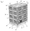
- FIG 1 shows, in perspective view, a transport assembly 10 according to a preferred embodiment of the invention.
- the transport assembly 10 comprises a transportation means 1.
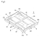
- the transportation means 1 comprises a pallet-like carrying structure 2 with two long sides 21, two short sides 22, four corners 23, an upper surface 24 and a lower surface 25.
- the carrying structure is provided with wheels 3 at each of the four corners 23 of which two of the wheels 3 are of the swivel castor wheel type 3'.
- the upper surface 24 is furthermore is provided with receiving means which are intended to receive the wheels 3 of a second transportation means 1 stacked on top of a first transportation means 1 so that a number of such transportation means 1 may be stacked, and fixated horizontally, one on top of the other.
- the upper surface 24 is provided with two narrow long side channels 26 arranged parallel to the long sides 21. Accordingly, these long side channels 26 are stretching from one short side 22 to the other.
- the long side channels 26 are placed at a distance from each other which is mainly equal to the distance between the wheels 3, as seen from a short side 22.
- the transportation means 1 may thus be placed one on top of the other by rolling them into engagement with each other in a lengthways direction. Referring now, again, to figure 1 .
- the transport assembly 10 further comprises a plurality of containers 4 stacked on top of the transportation means 1 and a lid 5 applied on top of the stack of containers 4. These containers 4 suitably has a horizontal dimension, a so-called foot-print, which is a multiple of the horizontal area of the transportation means 1.
- the foot-print area of the containers 4 may accordingly be 1/1, 1/2, 1/3, 1/4, 1/6, 1/8 etc. of the base area of the transportation means 1.
- the dimension of the transportation means 1 is 600 x 800 mm and the base dimension of the containers most commonly used hereon are 600 x 400 mm and 400 x 300 mm.
- the stack of containers 4 and the lid 5 is secured to the transportation means 1 by means of a tensional strap 6.
- the transport assembly 10 is secured from unauthorised tampering by means of providing the tensional strap 6 with a seal.
- the containers 4 are provided with a base and four foldable side walls so that they may be collapsed when having no content.
- the transport assembly 10 may alternatively be secured from unauthorised tampering by means of providing the transportation means 1, the containers 4 and the lid 5 with one or more seals.
- the lid 5 is provided with receiving means which are intended to receive the wheels 3 of a second transportation means 1 of a second transport assembly 10 stacked on top of a first transportation means 1 so that a plurality of such transport assemblies 10 may be stacked, and fixated horizontally, one on top of the other.
- the upper surface 54 of the lid 5 is provided with two parallel narrow long side channels 55 of the lid 5 stretching from one short side of the lid to the other.
- the long side channels 55 of the lid 5 is placed at a distance from each other which is mainly equal to the distance between the wheels 3, as seen from a short side 22.
- the transportation means 1 may hereby be placed on top of the lid 5 by rolling it into engagement with the lid 5 in a lengthways direction.
- the long side channels 55 of the lid 5 are provided with channel stoppers 55" of the lid 5 placed at a distance from each of the short side ends of the long side channels 55 of the lid 5. This distance is adapted to the radius of the wheels 3 so that a wheel 3 is prevented from moving inwards in the long side channel 55 of the lid 5.
- Inner channel stoppers 55" of the lid 5 are placed at a position corresponding to the vertical swivelling axis of the swivel castor wheels 3'.
Landscapes
- Engineering & Computer Science (AREA)
- Chemical & Material Sciences (AREA)
- Combustion & Propulsion (AREA)
- Transportation (AREA)
- Mechanical Engineering (AREA)
- Stackable Containers (AREA)
- Handcart (AREA)
Description
- The present invention relates to a transportation means comprising a pallet-like carrying structure provided with wheels a plurality of containers and a lid.
- Transportation means consisting of a carrying structure provided with wheels on the lower side has been known for a long time. They are most often of a format adapted to containers used for transportation an storage of goods. Most common formats, as seen from above, are 0.4 x 0.6 metres and 0.6 x 0.8 metres. The transportation means do, of course, need to be transported empty from time to time. In order to do that, the transportation means need to be stacked on top of each other. Since they are provided with wheels they will roll around and a stack will be impossible to handle. There are a number of way to secure such a stack.
One known such way is to alternately turn the transportation means 90° so that they rest, not on their wheels, but on the carrying structure itself. In order to secure the stack, the carrying structure is provided with guiding means on the rim. This solution is known fromGB 2 207 894
Another way to solve the problem is shown inGB 0 904 198
A slight improvement uponGB 0 904 198 EP 0 675 829 . The upper surface has here been provided with a bowl-like structure with a shape that corresponds to the radius of the swivel castor wheel as rotated around the swivelling axis. It will be a bit easier to position a transportation means according toEP 0 675 829 when compared toGB 0 904 198 - A variation of
EP 0 675 829 which also gives some improvement upon the same is known fromGB 2 281 897EP 0 675 829 have been provided with sloping partition walls guiding the wheels into four narrow pockets. The disadvantage with this solution is that swivel castor wheels might be stuck on top of the partition wall. You will furthermore have to position the transportation means rather exactly in order to make it fall into the correct position. - All of the above transportation means suffer from the disadvantage that they have to be positioned onto one another by being lowered from above in a more or less vertically aligned position when being stacked. This works rather well, although it is time consuming, as long as the stack is relatively low. It will however be rather difficult to position the transportation means when the stack reaches shoulder height and above. This is specially pronounced when they are heavy. There is also an ergonomic aspect to the stacking since the transportation means will have to be lifted into engagement. Neck, back and shoulder problems are most likely to occur if this stacking operation is repeated for a longer period of time.
- A transportation means which shows radical improvement on the ergonomic field is know from
WO 00/51898 claim 1. - The transportation means discussed above is most often used for transporting containers in short, controlled and closed loops like from a local bakery to a nearby supermarket. It is not possible to use this type of transport system for a more open type of transport of security reasons since it is very easy to tamper with this type of package. This is a problem that needs to be solved.
- According to the present invention a transport assembly which meets the requirement for a secure transport has been achieved. Accordingly, the invention relates to a transport assembly comprising a transportation means which comprises a pallet-like carrying structure. The pallet like carrying structure is provided with two long sides, two short sides, four corners, an upper surface and a lower surface. The carrying structure is also provided with wheels at each of the four corners of which at least two of the wheels possibly are of the swivel castor wheel type. The upper surface is furthermore provided with receiving means which are intended to receive the wheels of a second transportation means stacked on top of a first transportation means so that a number of such transportation means may be stacked, and fixated horizontally, one on top of the other. Thus, the upper surface is provided with two narrow long side channels arranged parallel to the long sides and which are stretching from one short side to the other. The long side channels are placed at a distance from each other which is mainly equal to the distance between the wheels, as seen from a short side. The transportation means may be placed one on top of the other by rolling them into engagement with each other in a lengthways direction. The invention is characterised in that the transport assembly further comprises a plurality of containers stacked on top of the transportation means and a lid applied on top of the stack of containers.
The stack of containers and the lid is preferably secured to the transportation means by means of tensional straps. According to a preferred embodiment of the invention the transport assembly is secured from unauthorised tampering by means of providing the tensional strap with a seal. It is according to another embodiment of the invention possible to secure the transport assembly from unauthorised tampering by means of providing the transportation means, the containers and the lid with one or more seals. It is for example possible to use a tensional strap which is used only once and which will have the double function of tensional strap as well as a seal. The tensional strap suitably compises a strap and a tensioning devise. According to one embodiment the tensioning device is integrated in the transportation means. It is hereby possible to arrange it flush with the outer surfaces of the transportation means. The tensioning device will hereby be protected from being damaged during transport. - According to one embodiment of the invention the containers are provided with a base and four foldable side walls. It will hereby be possible to reduce the transport volume when shipping empty containers.
- The lid is provided with receiving means which are intended to receive the wheels of a second transportation means of a second transport assembly stacked on top of a first transportation means so that a plurality of such transport assemblies may be stacked, and fixated horizontally, one on top of the other. The upper surface of the lid is provided with two parallel narrow long side channels of the lid, stretching from one short side of the lid to the other. The long side channels of the lid are placed at a distance from each other which is mainly equal to the distance between the wheels, as seen from a short side. The transportation means may be placed on top of the lid by rolling it into engagement with the lid in a lengthways direction.
The long side channels of the lid are suitably also provided with channel stoppers of the lid placed at a distance from each of the short side ends of the long side channels of the lid, which distance is adapted to the radius of the wheels so that a wheel is prevented from moving inwards in the long side channel of the lid. Inner channel stoppers of the lid are suitably placed at a position corresponding to the vertical swivelling axis of the swivel castor wheels. The lid is suitably provided with protrusions intended to interact with upper side wall edges of the containers on its lower side. This interaction resulting in stabilising a stack of containers. This stabilising effect is specially noted when the base area of the containers are 1/2,1/4, etc. the area of the transportation means, meaning that the stack of containers consist of 2, 4 etc. towers of containers arranged close together. The lid will here keep the containers together. - According to a preferred embodiment of the invention a plurality of containers, in a collapsed state, at least one, possibly a plurality of lids and at least one possibly a plurality of transportation means are assembled as a unit kept together by means of the tensional straps during empty return transport of said containers.
- The invention is explained further together with enclosed drawings, showing a preferred embodiment of the invention wherein,
-
figure 1 shows, in perspective view, a preferred embodiment of atransport assembly 10 according to the invention. -
figure 2 shows, in perspective a transportation means 1 shown infigure 1 . - Accordingly,
figure 1 shows, in perspective view, atransport assembly 10 according to a preferred embodiment of the invention. Thetransport assembly 10 comprises a transportation means 1.
Referring now tofigure 2 . The transportation means 1 comprises a pallet-like carrying structure 2 with twolong sides 21, twoshort sides 22, fourcorners 23, anupper surface 24 and a lower surface 25. The carrying structure is provided withwheels 3 at each of the fourcorners 23 of which two of thewheels 3 are of the swivel castor wheel type 3'. Theupper surface 24 is furthermore is provided with receiving means which are intended to receive thewheels 3 of a second transportation means 1 stacked on top of a first transportation means 1 so that a number of such transportation means 1 may be stacked, and fixated horizontally, one on top of the other. Theupper surface 24 is provided with two narrowlong side channels 26 arranged parallel to the long sides 21. Accordingly, theselong side channels 26 are stretching from oneshort side 22 to the other. Thelong side channels 26 are placed at a distance from each other which is mainly equal to the distance between thewheels 3, as seen from ashort side 22. The transportation means 1 may thus be placed one on top of the other by rolling them into engagement with each other in a lengthways direction.
Referring now, again, tofigure 1 . Thetransport assembly 10 further comprises a plurality ofcontainers 4 stacked on top of the transportation means 1 and alid 5 applied on top of the stack ofcontainers 4. Thesecontainers 4 suitably has a horizontal dimension, a so-called foot-print, which is a multiple of the horizontal area of the transportation means 1. The foot-print area of thecontainers 4 may accordingly be 1/1, 1/2, 1/3, 1/4, 1/6, 1/8 etc. of the base area of the transportation means 1. In one example the dimension of the transportation means 1 is 600 x 800 mm and the base dimension of the containers most commonly used hereon are 600 x 400 mm and 400 x 300 mm. The stack ofcontainers 4 and thelid 5 is secured to the transportation means 1 by means of atensional strap 6. Thetransport assembly 10 is secured from unauthorised tampering by means of providing thetensional strap 6 with a seal. In order to reduce transport volume when shipping thetransport assembly 10 empty thecontainers 4 are provided with a base and four foldable side walls so that they may be collapsed when having no content. It will in this way be possible to ship a plurality ofcontainers 4 in a collapsed state, a plurality oflids 5 and possibly a plurality of transportation means 1 which are assembled as a unit kept together by means of thetensional strap 6 during empty return transport of saidcontainers 4. Thetransport assembly 10 may alternatively be secured from unauthorised tampering by means of providing the transportation means 1, thecontainers 4 and thelid 5 with one or more seals.
Thelid 5 is provided with receiving means which are intended to receive thewheels 3 of a second transportation means 1 of asecond transport assembly 10 stacked on top of a first transportation means 1 so that a plurality ofsuch transport assemblies 10 may be stacked, and fixated horizontally, one on top of the other. Theupper surface 54 of thelid 5 is provided with two parallel narrowlong side channels 55 of thelid 5 stretching from one short side of the lid to the other. Thelong side channels 55 of thelid 5 is placed at a distance from each other which is mainly equal to the distance between thewheels 3, as seen from ashort side 22. The transportation means 1 may hereby be placed on top of thelid 5 by rolling it into engagement with thelid 5 in a lengthways direction. Thelong side channels 55 of thelid 5 are provided withchannel stoppers 55" of thelid 5 placed at a distance from each of the short side ends of thelong side channels 55 of thelid 5. This distance is adapted to the radius of thewheels 3 so that awheel 3 is prevented from moving inwards in thelong side channel 55 of thelid 5.Inner channel stoppers 55" of thelid 5 are placed at a position corresponding to the vertical swivelling axis of the swivel castor wheels 3'. - The invention is not limited to the embodiments shown, since it can be varied in different ways within the scope of the invention, as it is defined in the appended claims.
Claims (10)
- Transport assembly (10) comprising a transportation means (1) which comprises a pallet-like carrying structure (2) with two long sides (21), two short sides (22), four corners (23), an upper surface (24) and a lower surface (25),
the carrying structure being provided with wheels (3) at each of the four corners (23) of which at least two of the wheels (3) possibly are of the swivel castor wheel type (3'),
the upper surface (24) furthermore being provided with receiving means which are intended to receive the wheels (3) of a second transportation means (1) stacked on top of a first transportation means (1) so that a number of such transportation means may be stacked, and fixated horizontally, one on top of the other,
the upper surface (24) being provided with two narrow long side channels (26) arranged parallel to the long sides (21) and stretching from one short side (22) to the other, the long side channels (26) being placed at a distance from each other which is mainly equal to the distance between the wheels (3), as seen from a short side (22),
wherein transportation means (1) may be placed one on top of the other by rolling them into engagement with each other in a lengthways direction,
characterised in that
the transport assembly (10) further comprises a plurality of containers (4) stacked on top of the transportation means (1) and a lid (5) applied on top of the stack of containers (4), and
the lid (5) is provided with receiving means which are intended to receive the wheels (3) of a second transportation means (1) of a second transport assembly stacked on top of a first transportation means (1) so that a plurality of such transport assemblies (10) may be stacked, and fixated horizontally, one on top of the other,
an upper surface (54) of the lid (5) being provided with two parallel narrow long side channels (55) of the lid (5) stretching from one short side of the lid to the other, the long side channels (55) of the lid (5) being placed at a distance from each other which is mainly equal to the distance between the wheels (3), as seen from a short side (22),
wherein the transportation means (1) may be placed on top of the lid (5) by rolling it into engagement with the lid (5) in a lengthways direction. - Transport assembly (10) according to claim 1, wherein the stack of containers (4) and the lid (5) is secured to the.transportation means (1) by means of tensional straps (6).
- Transport assembly (10) according to claim 2, wherein the transport assembly (10) is secured from unauthorised tampering by means of providing the tensional strap with a seal.
- Transport assembly (10) according to claim 1, wherein the transport assembly (10) is secured from unauthorised tampering by means of providing the transportation means (1), the containers (4) and the lid (5) with one or more seals.
- Transport assembly (10) according to any one of claims 1 - 4, wherein the containers (4) are each provided with a base and four foldable side walls.
- Transport assembly (10) according to claim 1, wherein the long side channels (55) of the lid (5) are provided with channel stoppers (55') of the lid (5) placed at a distance from each of the short side ends of the long side channels (55) of the lid (5), which distance is adapted to the radius of the wheels (3) so that a wheel (3) is prevented from moving inwards or outwards in the long side channel (55) of the lid (5).
- Transport assembly (10) according to claim 6, wherein the inner channel stoppers (55") of the lid (5) are placed at a position corresponding to the vertical swivelling axis of the swivel castor wheels (3').
- Transport assembly (10) according to claim 1 or 2, wherein a plurality of containers (4) in a collapsed state, a plurality of lids (5) and possibly a plurality of transportation means (1) are assembled as a unit kept together by means of the tensional straps (6) during empty return transport of said containers (4).
- Transport assembly (10) according to claim 1, wherein the lid (5) is on its lower side provided with protrusions intended to interact with upper side wall edges of the containers (4), said interaction resulting in stabilising a stack of containers (4).
- Transport assembly (10) according to claim 2, wherein the tensional strap (6) comprises a strap and a tensioning device, said tensioning device being integrated in the transportation means (1).
Applications Claiming Priority (2)
| Application Number | Priority Date | Filing Date | Title |
|---|---|---|---|
| SE0302495A SE526880C2 (en) | 2003-09-19 | 2003-09-19 | transport assembly |
| PCT/SE2004/001339 WO2005028276A1 (en) | 2003-09-19 | 2004-09-16 | Transport assembly |
Publications (2)
| Publication Number | Publication Date |
|---|---|
| EP1663758A1 EP1663758A1 (en) | 2006-06-07 |
| EP1663758B1 true EP1663758B1 (en) | 2009-07-15 |
Family
ID=29212497
Family Applications (1)
| Application Number | Title | Priority Date | Filing Date |
|---|---|---|---|
| EP04775442A Expired - Lifetime EP1663758B1 (en) | 2003-09-19 | 2004-09-16 | Transport assembly |
Country Status (6)
| Country | Link |
|---|---|
| US (1) | US7530580B2 (en) |
| EP (1) | EP1663758B1 (en) |
| DE (1) | DE602004022062D1 (en) |
| ES (1) | ES2329043T3 (en) |
| SE (1) | SE526880C2 (en) |
| WO (1) | WO2005028276A1 (en) |
Cited By (2)
| Publication number | Priority date | Publication date | Assignee | Title |
|---|---|---|---|---|
| CN102774593A (en) * | 2012-08-01 | 2012-11-14 | 张家港市恒美纺织有限公司 | Scroll transport vehicle |
| CN111469894A (en) * | 2020-04-15 | 2020-07-31 | 广东鼎湖山泉有限公司 | Multilayer stacking and transporting device for packaged drinking water and storing, taking and transporting method thereof |
Families Citing this family (12)
| Publication number | Priority date | Publication date | Assignee | Title |
|---|---|---|---|---|
| GB0518087D0 (en) * | 2005-09-06 | 2005-10-12 | Bekaert Handling Ltd | Dolly and lid combination |
| US7765744B2 (en) * | 2006-12-15 | 2010-08-03 | Global Shelter Systems, Inc. | Construction block |
| US8209916B2 (en) * | 2008-07-21 | 2012-07-03 | Global Shelter Systems, Inc. | Construction block |
| WO2010127453A1 (en) * | 2009-05-06 | 2010-11-11 | Simoes Paulo G | Stackable and collapsible trolley cart system |
| US10583851B2 (en) * | 2013-09-18 | 2020-03-10 | Allpillars, Inc. | Food, water and vital supplies storage and transport cart |
| US9694837B2 (en) * | 2013-09-18 | 2017-07-04 | Allpillars, Inc. | Collapsible reusable carrying cases |
| US9550605B1 (en) | 2014-08-29 | 2017-01-24 | Matthew A. Summers | Nesting container assembly |
| US10442568B1 (en) | 2014-08-29 | 2019-10-15 | Matthew A. Summers | Nesting container and nesting container assembly |
| USD1000113S1 (en) | 2015-08-28 | 2023-10-03 | Summers Matthew A | Container |
| USD808164S1 (en) | 2015-08-28 | 2018-01-23 | Matthew A. Summers | Container |
| ES2918508T3 (en) | 2016-01-28 | 2022-07-18 | Chep Technology Pty Ltd | Cheek |
| US9648949B1 (en) * | 2016-02-15 | 2017-05-16 | Ronaldo Green Penaflor | Vinyl wrap hanger and stand |
Family Cites Families (12)
| Publication number | Priority date | Publication date | Assignee | Title |
|---|---|---|---|---|
| US4000704A (en) * | 1974-10-18 | 1977-01-04 | Burlington Industries, Inc. | Shipping pallet |
| US5186330A (en) * | 1991-12-27 | 1993-02-16 | Mcclure Industries, Inc. | Stackable container |
| JP3234962B2 (en) * | 1993-07-23 | 2001-12-04 | 三菱樹脂株式会社 | Transport container lid and binding rod |
| US5564805A (en) * | 1994-01-03 | 1996-10-15 | Contico International, Inc. | Storage container with wheels |
| US5865315A (en) | 1997-01-06 | 1999-02-02 | Uitz; Mark O | Material transport system |
| US5829595A (en) * | 1997-03-03 | 1998-11-03 | Trienda Corporation | Thin sheet thermoformed pallet sleeve |
| US6024223A (en) * | 1999-02-04 | 2000-02-15 | Technology Container Corporation | Storage container including a mounting clip an associated mounting clip, and an associated method |
| SE514517C2 (en) | 1999-03-01 | 2001-03-05 | Arca Systems Ab | Transport device which includes a pallet-like structure with wheels |
| US20020124527A1 (en) | 2001-03-12 | 2002-09-12 | Koorosh Vafadari | Pallete seal and method for securing a pallete |
| US6439131B1 (en) * | 2001-04-27 | 2002-08-27 | Joseph M. Higgins | Convertible highway and rail freight vehicle |
| US6983946B2 (en) * | 2003-04-01 | 2006-01-10 | Porta Plastic Products | Transportable containers apparatus and method |
| EP1495937B1 (en) * | 2003-07-10 | 2010-01-06 | Georg Utz Holding AG | Transport trolley |
-
2003
- 2003-09-19 SE SE0302495A patent/SE526880C2/en not_active IP Right Cessation
-
2004
- 2004-09-16 EP EP04775442A patent/EP1663758B1/en not_active Expired - Lifetime
- 2004-09-16 DE DE602004022062T patent/DE602004022062D1/en not_active Expired - Lifetime
- 2004-09-16 WO PCT/SE2004/001339 patent/WO2005028276A1/en not_active Ceased
- 2004-09-16 ES ES04775442T patent/ES2329043T3/en not_active Expired - Lifetime
- 2004-09-16 US US10/572,546 patent/US7530580B2/en not_active Expired - Fee Related
Cited By (3)
| Publication number | Priority date | Publication date | Assignee | Title |
|---|---|---|---|---|
| CN102774593A (en) * | 2012-08-01 | 2012-11-14 | 张家港市恒美纺织有限公司 | Scroll transport vehicle |
| CN111469894A (en) * | 2020-04-15 | 2020-07-31 | 广东鼎湖山泉有限公司 | Multilayer stacking and transporting device for packaged drinking water and storing, taking and transporting method thereof |
| CN111469894B (en) * | 2020-04-15 | 2021-01-29 | 广东鼎湖山泉有限公司 | Multilayer stacking and transporting device for packaged drinking water and storing, taking and transporting method thereof |
Also Published As
| Publication number | Publication date |
|---|---|
| SE0302495D0 (en) | 2003-09-19 |
| WO2005028276A1 (en) | 2005-03-31 |
| SE526880C2 (en) | 2005-11-15 |
| US20060277867A1 (en) | 2006-12-14 |
| SE0302495L (en) | 2005-03-20 |
| US7530580B2 (en) | 2009-05-12 |
| EP1663758A1 (en) | 2006-06-07 |
| DE602004022062D1 (en) | 2009-08-27 |
| ES2329043T3 (en) | 2009-11-20 |
Similar Documents
| Publication | Publication Date | Title |
|---|---|---|
| EP1663758B1 (en) | Transport assembly | |
| US8066149B2 (en) | Stackable container with support structure | |
| US7721891B2 (en) | Nest and stacked containers | |
| US6131730A (en) | Stackable container case | |
| US7252196B1 (en) | Crate for bottles and other containers | |
| US5538153A (en) | Folding crate for holding packages | |
| US9010531B2 (en) | Bulk bag carrier with pallet | |
| US20090266782A1 (en) | Stackable ribbed bottle system | |
| EP3978381B1 (en) | Bulk container with interlocking elements | |
| US20080264820A1 (en) | Stackable container apparatus and methods | |
| US20060060580A1 (en) | Collapsible container for transport and storage of goods | |
| US5503275A (en) | Crates with stacking and nesting methods | |
| SK103096A3 (en) | Crate for bottles | |
| GB2445878A (en) | Collapsible crate with movable and/or removable portion | |
| CN114174197A (en) | Transport container | |
| US7467714B2 (en) | Container stack and separating element therefor | |
| KR200482115Y1 (en) | multi heaping and carrying cart | |
| US20210331832A1 (en) | Collapsible storage and transportation unit | |
| US20020195027A1 (en) | Pallet | |
| US20070059119A1 (en) | Storage system and method of use of the same | |
| EP1165385B1 (en) | Transportation means | |
| US20100187141A1 (en) | Bulk container | |
| CN1006541B (en) | Container with sleeve interlocking latch | |
| US20050224386A1 (en) | Lightweight interlocking container | |
| WO2019198066A1 (en) | A container |
Legal Events
| Date | Code | Title | Description |
|---|---|---|---|
| PUAI | Public reference made under article 153(3) epc to a published international application that has entered the european phase |
Free format text: ORIGINAL CODE: 0009012 |
|
| 17P | Request for examination filed |
Effective date: 20060317 |
|
| AK | Designated contracting states |
Kind code of ref document: A1 Designated state(s): AT BE BG CH CY CZ DE DK EE ES FI FR GB GR HU IE IT LI LU MC NL PL PT RO SE SI SK TR |
|
| 17Q | First examination report despatched |
Effective date: 20061122 |
|
| DAX | Request for extension of the european patent (deleted) | ||
| RAP1 | Party data changed (applicant data changed or rights of an application transferred) |
Owner name: SCHOELLER ARCA SYSTEMS AB |
|
| GRAP | Despatch of communication of intention to grant a patent |
Free format text: ORIGINAL CODE: EPIDOSNIGR1 |
|
| GRAS | Grant fee paid |
Free format text: ORIGINAL CODE: EPIDOSNIGR3 |
|
| GRAA | (expected) grant |
Free format text: ORIGINAL CODE: 0009210 |
|
| AK | Designated contracting states |
Kind code of ref document: B1 Designated state(s): AT BE BG CH CY CZ DE DK EE ES FI FR GB GR HU IE IT LI LU MC NL PL PT RO SE SI SK TR |
|
| REG | Reference to a national code |
Ref country code: CH Ref legal event code: EP Ref country code: GB Ref legal event code: FG4D |
|
| REG | Reference to a national code |
Ref country code: IE Ref legal event code: FG4D |
|
| REF | Corresponds to: |
Ref document number: 602004022062 Country of ref document: DE Date of ref document: 20090827 Kind code of ref document: P |
|
| REG | Reference to a national code |
Ref country code: ES Ref legal event code: FG2A Ref document number: 2329043 Country of ref document: ES Kind code of ref document: T3 |
|
| PG25 | Lapsed in a contracting state [announced via postgrant information from national office to epo] |
Ref country code: SE Free format text: LAPSE BECAUSE OF FAILURE TO SUBMIT A TRANSLATION OF THE DESCRIPTION OR TO PAY THE FEE WITHIN THE PRESCRIBED TIME-LIMIT Effective date: 20090715 Ref country code: FI Free format text: LAPSE BECAUSE OF FAILURE TO SUBMIT A TRANSLATION OF THE DESCRIPTION OR TO PAY THE FEE WITHIN THE PRESCRIBED TIME-LIMIT Effective date: 20090715 Ref country code: AT Free format text: LAPSE BECAUSE OF FAILURE TO SUBMIT A TRANSLATION OF THE DESCRIPTION OR TO PAY THE FEE WITHIN THE PRESCRIBED TIME-LIMIT Effective date: 20090715 |
|
| PG25 | Lapsed in a contracting state [announced via postgrant information from national office to epo] |
Ref country code: SI Free format text: LAPSE BECAUSE OF FAILURE TO SUBMIT A TRANSLATION OF THE DESCRIPTION OR TO PAY THE FEE WITHIN THE PRESCRIBED TIME-LIMIT Effective date: 20090715 Ref country code: PL Free format text: LAPSE BECAUSE OF FAILURE TO SUBMIT A TRANSLATION OF THE DESCRIPTION OR TO PAY THE FEE WITHIN THE PRESCRIBED TIME-LIMIT Effective date: 20090715 |
|
| PG25 | Lapsed in a contracting state [announced via postgrant information from national office to epo] |
Ref country code: BG Free format text: LAPSE BECAUSE OF FAILURE TO SUBMIT A TRANSLATION OF THE DESCRIPTION OR TO PAY THE FEE WITHIN THE PRESCRIBED TIME-LIMIT Effective date: 20091015 Ref country code: PT Free format text: LAPSE BECAUSE OF FAILURE TO SUBMIT A TRANSLATION OF THE DESCRIPTION OR TO PAY THE FEE WITHIN THE PRESCRIBED TIME-LIMIT Effective date: 20091115 |
|
| PG25 | Lapsed in a contracting state [announced via postgrant information from national office to epo] |
Ref country code: RO Free format text: LAPSE BECAUSE OF FAILURE TO SUBMIT A TRANSLATION OF THE DESCRIPTION OR TO PAY THE FEE WITHIN THE PRESCRIBED TIME-LIMIT Effective date: 20090715 Ref country code: EE Free format text: LAPSE BECAUSE OF FAILURE TO SUBMIT A TRANSLATION OF THE DESCRIPTION OR TO PAY THE FEE WITHIN THE PRESCRIBED TIME-LIMIT Effective date: 20090715 Ref country code: DK Free format text: LAPSE BECAUSE OF FAILURE TO SUBMIT A TRANSLATION OF THE DESCRIPTION OR TO PAY THE FEE WITHIN THE PRESCRIBED TIME-LIMIT Effective date: 20090715 Ref country code: MC Free format text: LAPSE BECAUSE OF NON-PAYMENT OF DUE FEES Effective date: 20090930 Ref country code: CZ Free format text: LAPSE BECAUSE OF FAILURE TO SUBMIT A TRANSLATION OF THE DESCRIPTION OR TO PAY THE FEE WITHIN THE PRESCRIBED TIME-LIMIT Effective date: 20090715 |
|
| REG | Reference to a national code |
Ref country code: CH Ref legal event code: PL |
|
| PLBE | No opposition filed within time limit |
Free format text: ORIGINAL CODE: 0009261 |
|
| STAA | Information on the status of an ep patent application or granted ep patent |
Free format text: STATUS: NO OPPOSITION FILED WITHIN TIME LIMIT |
|
| PG25 | Lapsed in a contracting state [announced via postgrant information from national office to epo] |
Ref country code: BE Free format text: LAPSE BECAUSE OF FAILURE TO SUBMIT A TRANSLATION OF THE DESCRIPTION OR TO PAY THE FEE WITHIN THE PRESCRIBED TIME-LIMIT Effective date: 20090715 Ref country code: SK Free format text: LAPSE BECAUSE OF FAILURE TO SUBMIT A TRANSLATION OF THE DESCRIPTION OR TO PAY THE FEE WITHIN THE PRESCRIBED TIME-LIMIT Effective date: 20090715 |
|
| 26N | No opposition filed |
Effective date: 20100416 |
|
| PG25 | Lapsed in a contracting state [announced via postgrant information from national office to epo] |
Ref country code: IE Free format text: LAPSE BECAUSE OF NON-PAYMENT OF DUE FEES Effective date: 20090916 |
|
| PG25 | Lapsed in a contracting state [announced via postgrant information from national office to epo] |
Ref country code: LI Free format text: LAPSE BECAUSE OF NON-PAYMENT OF DUE FEES Effective date: 20090930 Ref country code: CH Free format text: LAPSE BECAUSE OF NON-PAYMENT OF DUE FEES Effective date: 20090930 Ref country code: GR Free format text: LAPSE BECAUSE OF FAILURE TO SUBMIT A TRANSLATION OF THE DESCRIPTION OR TO PAY THE FEE WITHIN THE PRESCRIBED TIME-LIMIT Effective date: 20091016 |
|
| PG25 | Lapsed in a contracting state [announced via postgrant information from national office to epo] |
Ref country code: IT Free format text: LAPSE BECAUSE OF FAILURE TO SUBMIT A TRANSLATION OF THE DESCRIPTION OR TO PAY THE FEE WITHIN THE PRESCRIBED TIME-LIMIT Effective date: 20090715 |
|
| PG25 | Lapsed in a contracting state [announced via postgrant information from national office to epo] |
Ref country code: LU Free format text: LAPSE BECAUSE OF NON-PAYMENT OF DUE FEES Effective date: 20090916 |
|
| PG25 | Lapsed in a contracting state [announced via postgrant information from national office to epo] |
Ref country code: HU Free format text: LAPSE BECAUSE OF FAILURE TO SUBMIT A TRANSLATION OF THE DESCRIPTION OR TO PAY THE FEE WITHIN THE PRESCRIBED TIME-LIMIT Effective date: 20100116 |
|
| PG25 | Lapsed in a contracting state [announced via postgrant information from national office to epo] |
Ref country code: TR Free format text: LAPSE BECAUSE OF FAILURE TO SUBMIT A TRANSLATION OF THE DESCRIPTION OR TO PAY THE FEE WITHIN THE PRESCRIBED TIME-LIMIT Effective date: 20090715 |
|
| PG25 | Lapsed in a contracting state [announced via postgrant information from national office to epo] |
Ref country code: CY Free format text: LAPSE BECAUSE OF FAILURE TO SUBMIT A TRANSLATION OF THE DESCRIPTION OR TO PAY THE FEE WITHIN THE PRESCRIBED TIME-LIMIT Effective date: 20090715 |
|
| PGFP | Annual fee paid to national office [announced via postgrant information from national office to epo] |
Ref country code: DE Payment date: 20120924 Year of fee payment: 9 Ref country code: ES Payment date: 20120921 Year of fee payment: 9 |
|
| PGFP | Annual fee paid to national office [announced via postgrant information from national office to epo] |
Ref country code: NL Payment date: 20120925 Year of fee payment: 9 Ref country code: FR Payment date: 20121012 Year of fee payment: 9 |
|
| REG | Reference to a national code |
Ref country code: NL Ref legal event code: V1 Effective date: 20140401 |
|
| REG | Reference to a national code |
Ref country code: DE Ref legal event code: R119 Ref document number: 602004022062 Country of ref document: DE Effective date: 20140401 |
|
| REG | Reference to a national code |
Ref country code: FR Ref legal event code: ST Effective date: 20140530 |
|
| PG25 | Lapsed in a contracting state [announced via postgrant information from national office to epo] |
Ref country code: FR Free format text: LAPSE BECAUSE OF NON-PAYMENT OF DUE FEES Effective date: 20130930 Ref country code: DE Free format text: LAPSE BECAUSE OF NON-PAYMENT OF DUE FEES Effective date: 20140401 Ref country code: NL Free format text: LAPSE BECAUSE OF NON-PAYMENT OF DUE FEES Effective date: 20140401 |
|
| REG | Reference to a national code |
Ref country code: ES Ref legal event code: FD2A Effective date: 20150709 |
|
| PG25 | Lapsed in a contracting state [announced via postgrant information from national office to epo] |
Ref country code: ES Free format text: LAPSE BECAUSE OF NON-PAYMENT OF DUE FEES Effective date: 20130917 |
|
| PGFP | Annual fee paid to national office [announced via postgrant information from national office to epo] |
Ref country code: GB Payment date: 20190924 Year of fee payment: 16 |
|
| GBPC | Gb: european patent ceased through non-payment of renewal fee |
Effective date: 20200916 |
|
| PG25 | Lapsed in a contracting state [announced via postgrant information from national office to epo] |
Ref country code: GB Free format text: LAPSE BECAUSE OF NON-PAYMENT OF DUE FEES Effective date: 20200916 |