EP1663678B1 - Booster with spring to adapt air spring pressure for load dependent shock absorber - Google Patents
Booster with spring to adapt air spring pressure for load dependent shock absorber Download PDFInfo
- Publication number
- EP1663678B1 EP1663678B1 EP04783454A EP04783454A EP1663678B1 EP 1663678 B1 EP1663678 B1 EP 1663678B1 EP 04783454 A EP04783454 A EP 04783454A EP 04783454 A EP04783454 A EP 04783454A EP 1663678 B1 EP1663678 B1 EP 1663678B1
- Authority
- EP
- European Patent Office
- Prior art keywords
- piston
- working chamber
- booster
- chamber
- suspension system
- Prior art date
- Legal status (The legal status is an assumption and is not a legal conclusion. Google has not performed a legal analysis and makes no representation as to the accuracy of the status listed.)
- Expired - Lifetime
Links
- 230000035939 shock Effects 0.000 title claims description 46
- 230000001419 dependent effect Effects 0.000 title claims description 15
- 239000006096 absorbing agent Substances 0.000 title description 39
- 239000000725 suspension Substances 0.000 claims description 31
- 239000012530 fluid Substances 0.000 claims description 14
- 230000000694 effects Effects 0.000 claims description 2
- WUBBRNOQWQTFEX-UHFFFAOYSA-N 4-aminosalicylic acid Chemical compound NC1=CC=C(C(O)=O)C(O)=C1 WUBBRNOQWQTFEX-UHFFFAOYSA-N 0.000 description 9
- 230000003068 static effect Effects 0.000 description 8
- 230000003466 anti-cipated effect Effects 0.000 description 2
- 230000000712 assembly Effects 0.000 description 2
- 238000000429 assembly Methods 0.000 description 2
- 238000013016 damping Methods 0.000 description 2
- 230000008846 dynamic interplay Effects 0.000 description 2
- 230000001939 inductive effect Effects 0.000 description 2
- 230000007935 neutral effect Effects 0.000 description 1
Images

Classifications
-
- B—PERFORMING OPERATIONS; TRANSPORTING
- B60—VEHICLES IN GENERAL
- B60G—VEHICLE SUSPENSION ARRANGEMENTS
- B60G15/00—Resilient suspensions characterised by arrangement, location or type of combined spring and vibration damper, e.g. telescopic type
- B60G15/08—Resilient suspensions characterised by arrangement, location or type of combined spring and vibration damper, e.g. telescopic type having fluid spring
- B60G15/12—Resilient suspensions characterised by arrangement, location or type of combined spring and vibration damper, e.g. telescopic type having fluid spring and fluid damper
- B60G15/14—Resilient suspensions characterised by arrangement, location or type of combined spring and vibration damper, e.g. telescopic type having fluid spring and fluid damper the damper being connected to the stub axle and the spring being arranged around the damper
-
- B—PERFORMING OPERATIONS; TRANSPORTING
- B60—VEHICLES IN GENERAL
- B60G—VEHICLE SUSPENSION ARRANGEMENTS
- B60G11/00—Resilient suspensions characterised by arrangement, location or kind of springs
- B60G11/26—Resilient suspensions characterised by arrangement, location or kind of springs having fluid springs only, e.g. hydropneumatic springs
- B60G11/27—Resilient suspensions characterised by arrangement, location or kind of springs having fluid springs only, e.g. hydropneumatic springs wherein the fluid is a gas
-
- B—PERFORMING OPERATIONS; TRANSPORTING
- B60—VEHICLES IN GENERAL
- B60G—VEHICLE SUSPENSION ARRANGEMENTS
- B60G11/00—Resilient suspensions characterised by arrangement, location or kind of springs
- B60G11/32—Resilient suspensions characterised by arrangement, location or kind of springs having springs of different kinds
- B60G11/48—Resilient suspensions characterised by arrangement, location or kind of springs having springs of different kinds not including leaf springs
- B60G11/56—Resilient suspensions characterised by arrangement, location or kind of springs having springs of different kinds not including leaf springs having helical, spiral or coil springs, and also fluid springs
- B60G11/58—Resilient suspensions characterised by arrangement, location or kind of springs having springs of different kinds not including leaf springs having helical, spiral or coil springs, and also fluid springs arranged coaxially
-
- B—PERFORMING OPERATIONS; TRANSPORTING
- B60—VEHICLES IN GENERAL
- B60G—VEHICLE SUSPENSION ARRANGEMENTS
- B60G13/00—Resilient suspensions characterised by arrangement, location or type of vibration dampers
- B60G13/02—Resilient suspensions characterised by arrangement, location or type of vibration dampers having dampers dissipating energy, e.g. frictionally
- B60G13/06—Resilient suspensions characterised by arrangement, location or type of vibration dampers having dampers dissipating energy, e.g. frictionally of fluid type
- B60G13/10—Resilient suspensions characterised by arrangement, location or type of vibration dampers having dampers dissipating energy, e.g. frictionally of fluid type pneumatic
-
- B—PERFORMING OPERATIONS; TRANSPORTING
- B60—VEHICLES IN GENERAL
- B60G—VEHICLE SUSPENSION ARRANGEMENTS
- B60G17/00—Resilient suspensions having means for adjusting the spring or vibration-damper characteristics, for regulating the distance between a supporting surface and a sprung part of vehicle or for locking suspension during use to meet varying vehicular or surface conditions, e.g. due to speed or load
- B60G17/02—Spring characteristics, e.g. mechanical springs and mechanical adjusting means
- B60G17/04—Spring characteristics, e.g. mechanical springs and mechanical adjusting means fluid spring characteristics
- B60G17/0416—Spring characteristics, e.g. mechanical springs and mechanical adjusting means fluid spring characteristics regulated by varying the resiliency of hydropneumatic suspensions
- B60G17/0424—Spring characteristics, e.g. mechanical springs and mechanical adjusting means fluid spring characteristics regulated by varying the resiliency of hydropneumatic suspensions by varying the air pressure of the accumulator
-
- B—PERFORMING OPERATIONS; TRANSPORTING
- B60—VEHICLES IN GENERAL
- B60G—VEHICLE SUSPENSION ARRANGEMENTS
- B60G17/00—Resilient suspensions having means for adjusting the spring or vibration-damper characteristics, for regulating the distance between a supporting surface and a sprung part of vehicle or for locking suspension during use to meet varying vehicular or surface conditions, e.g. due to speed or load
- B60G17/06—Characteristics of dampers, e.g. mechanical dampers
- B60G17/08—Characteristics of fluid dampers
Definitions
- the present invention relates to frequency dependent dampers or shock absorbers, and more particularly to a booster to adapt air spring pressure for a load dependent shock absorber.
- shock absorbers are used in conjunction with automotive suspension systems to absorb unwanted vibrations which occur during driving. To absorb these unwanted vibrations, shock absorbers are generally connected between the sprung portion (body) and the unsprung portion (suspension) of the automobile.
- a piston is located within a pressure tube of the shock absorber and the pressure tube is normally attached to the unsprung portion of the vehicle.
- the piston is normally attached to the sprung portion of the vehicle through a piston rod which extends through the pressure tube.
- the piston divides the pressure tube into an upper working chamber and a lower working chamber. The shock absorber, by restricting fluid flow between the upper and lower working chambers, produces a damping force that counteracts the vibration that would otherwise be transmitted from the unsprung portion of the vehicle to the sprung portion of the vehicle.
- Spring devices are implemented with the shock absorbers to resiliently support the vehicle on the suspension system.
- Exemplary spring devices include coil springs, torsion bars and air springs. As the vehicle load increases the spring devices compress. The dampening capability of the shock absorbers, however, remains constant regardless of the vehicle load. While a constant dampening ability may be acceptable in some applications, other applications would benefit from a shock absorber whose dampening characteristics vary with vehicle load.
- the present invention provides a suspension system for a vehicle, which includes a shock absorber with variable dampening capability.
- the suspension system includes a frequency dependent damper (FDD) or shock absorber defining a first pressurized working chamber and an air spring assembly defining a second pressurized working chamber.
- FDD frequency dependent damper
- a booster enables pressure communication between the first pressurized working chamber and the second pressurized working chamber.
- the booster includes a resilient member that effects booster performance.
- the booster includes a housing defining segmented chambers and a piston assembly slidably disposed within the segmented chambers.
- the piston assembly includes a first piston dividing a first segmented chamber and a second segmented chamber and a second piston interconnected with the first piston and dividing the second segmented chamber and a third segmented chamber.
- the first segmented chamber is in fluid communication with the second pressurized working chamber and the third working chamber is in fluid communication with the first pressurized working chamber.
- the first piston is of a larger diameter than the second piston. The resilient member biases the first piston.
- a restrictor is disposed between the air spring assembly and the booster to inhibit pressurized fluid flow therebetween.
- the booster includes a housing defining a chamber and a piston slidably disposed within the chamber to define segmented chambers.
- the resilient member biases said piston.
- Figure 1 is a perspective view of a vehicle having a suspension incorporating frequency dependent dampers according to the present invention
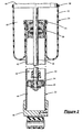
- Figure 2 is a cross-sectional side view of an integrated shock assembly including a frequency dependent damper and an air spring assembly;
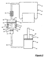
- Figure 3 is a schematic view of the suspension including the frequency dependent damper, air spring assembly and a booster according to the present invention.
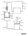
- Figure 4 is a schematic view of the suspension including the frequency dependent damper, air spring assembly and an alternative booster according to the present invention.
- a vehicle 10 includes a rear suspension system 12, a front suspension system 14 and a body 16.
- the rear suspension system 12 includes a pair of independent suspensions 18 supporting a pair of rear wheels 20. Each rear independent suspension 18 is attached to the body 16 by means of a frequency dependent damper or shock absorber 22 and an air spring assembly 24.
- the front suspension system 14 includes a pair of independent suspensions 26 supporting a pair of front wheels 28. Each independent front suspension 26 is attached to the body 16 and includes an integrated shock assembly 30 having the shock absorber 22 and an air spring assembly 24.
- the shock absorbers 22 dampen the relative movement of the unsprung portion (i.e., the front and rear suspension systems 12 and 14) of the vehicle 10 with respect to the sprung portion (i.e., the body 16) of the vehicle 10. While the vehicle 10 has been depicted as a passenger vehicle having independent front and rear suspensions, the shock absorbers 22 and air spring assemblies 24 may be incorporated into other types of vehicles having other types of suspensions. It is also anticipated that the shock absorbers 22 and air spring assemblies 24 may be incorporated into other types of applications, inducing, but not limited to, vehicles having air springs, leaf springs, non-independent front and/or non-independent rear suspension systems. Further, the term "shock absorber" as used herein is meant to refer to dampers in general and thus includes MacPherson struts, spring seat units, as well as other shock absorber designs known in the art.
- the integrated shock assembly 30 includes the shock absorber 22 and the air spring assembly 24.
- the shock absorber 22 is disclosed in detail in commonly assigned U.S. Patent Application No. 09/778,455, filed February 7, 2001 and published as US-A-2002/0104724 .
- the shock absorber 22 includes a pressure tube 32, a piston assembly 34, a piston rod 36 and a rod guide assembly 38.
- the pressure tube 32 defines a working chamber 40 that is filled with a gas, preferably air, at a specified pressure to act as the damping medium.
- the piston assembly 34 is slidably disposed within the working chamber 40 and divides the working chamber 40 into an upper working chamber 42 and a lower working chamber 44.
- a seal assembly 46 is disposed between the piston assembly 34 and the pressure tube 32 to enable sliding movement of piston assembly 34 within the pressure tube 32 without generating undue frictional forces.
- the seal assembly 46 seals the upper working chamber 42 from the lower working chamber 44.
- the piston rod 36 is attached to the piston assembly 34 and extends through the upper working chamber 42 and through the rod guide assembly 38, which closes the upper end of the pressure tube 32.
- the end of the piston rod 36 opposite to the piston assembly 34 is secured to a sprung portion of the vehicle 10 via an upper mount assembly 48.
- the end of pressure tube 32 opposite to the rod guide assembly 38 is closed by an end cap 50 that is connected to an unsprung portion of the vehicle 10. It is also anticipated that the piston rod 36 can be attached to the unsprung portion of the vehicle 10 and the end cap 50 attached to the sprung portion of the vehicle 10.
- the air spring assembly 24 of the integrated shock assembly 30 comprises a flexible bladder 52 which is secured to the shock absorber 22 using a retainer 54 and which is secured to the upper mount assembly 48 by a retainer 56.
- the bladder 52 defines chamber 58 that contains pressurized gas for supporting the body 16 of the vehicle 10.
- the chamber 58 of the bladder 52 and the lower working chamber 44 of the shock absorber 22 are pressure-dependent on one another through a booster 60.
- the booster 60 boosts the air pressure within the lower working chamber 44 of the shock absorber 22.
- the booster 60 includes a housing 62 and a piston assembly 64 slidably disposed therein.
- the housing 62 defines a working chamber 66 that is separated into a first working chamber 68, a second or intermediate working chamber 70 and a third working chamber 72 by the piston assembly 64.
- the piston assembly 64 includes a large diameter piston 74 slidably disposed in a first section 76 of the housing 62 and a small diameter piston 78 slidably disposed within a second section 80 of the housing 62.
- the large diameter piston 74 is connected to the small diameter piston 78 by a piston rod 82.
- the first working chamber 68 is in fluid communication with the chamber 58 of the air spring assembly 24 through a conduit 84.
- the intermediate working chamber 70 is in fluid communication with atmosphere through a vent 86.
- the third working chamber 72 is in fluid communication with the lower working chamber 44 of the shock absorber 22 through a conduit 88.
- a restrictor 90 is optionally provided to restrict fluid flow through the conduit 84. The restrictor 90 inhibits dynamic interaction between the air spring assembly 24 and the shock absorber 22.
- a resilient member 92 is optionally provided to influence sliding movement of the piston assembly 64. The resilient member 92 applies a reaction force against the piston assembly 64 as the piston assembly 64 compresses the resilient member 92.
- the air pressure within the air spring assembly 24 is lower than the pressure within the shock absorber 22.
- the booster 60 enables boosting of the air pressure within the shock absorber 22 and adjustment of the power dissipation ability of the shock absorber 22 based on the load of the vehicle 10.
- F LOAD acts on the air spring assembly 24 until a static state is achieved.
- F LOAD increases the pressure (P ASA ) within the air spring assembly 24.
- P ASA acts across the surface area (A LDP ) of the large diameter piston 74 applying a force (F LDP ) and inducing movement of the large diameter piston 74.
- the large diameter piston 74 moves until the static state is achieved.
- the booster 60' adapts the air pressure within the chamber 58 of the air spring assembly 24 and the air pressure within the lower working chamber 44 of the shock absorber 22.
- the booster 60 includes a housing 62' and a piston 64' slidably disposed therein.
- the housing 62' defines a working chamber 66' that is separated into a first working chamber 68' and a second working chamber 70' by the piston 64'.
- a resilient member 92' is disposed within the first working chamber and biases the piston 64'. More specifically, the resilient member 92' maintains the piston 64' in a neutral position when the vehicle 10 is unladen.
- the first working chamber 68' is in fluid communication with the chamber 58 of the air spring assembly 24 through the conduit 84.
- the second working chamber 70' is in fluid communication with the lower working chamber 44 of the shock absorber 22 through the conduit 88.
- the restrictor 90 is optionally provided to restrict fluid flow through the conduit 84. The restrictor 90 inhibits dynamic interaction between the air spring assembly 24 and the shock absorber 22.
- the boosters 60 and 60' between the air spring assembly 24 and the shock absorber 22 enables a load dependent shock absorber 22. More specifically, the power dissipated by the shock absorber 22 is a function of the static pressure therewithin. The air pressure within the air spring assembly 24 is proportional to the load of the vehicle 20. The booster 60 enables use of the air pressure within the air spring assembly 24 to adapt the pressure within the shock absorber 22.
Landscapes
- Engineering & Computer Science (AREA)
- Mechanical Engineering (AREA)
- Vehicle Body Suspensions (AREA)
- Fluid-Damping Devices (AREA)
Description
- The present invention relates to frequency dependent dampers or shock absorbers, and more particularly to a booster to adapt air spring pressure for a load dependent shock absorber.
- Shock absorbers are used in conjunction with automotive suspension systems to absorb unwanted vibrations which occur during driving. To absorb these unwanted vibrations, shock absorbers are generally connected between the sprung portion (body) and the unsprung portion (suspension) of the automobile. A piston is located within a pressure tube of the shock absorber and the pressure tube is normally attached to the unsprung portion of the vehicle. The piston is normally attached to the sprung portion of the vehicle through a piston rod which extends through the pressure tube. The piston divides the pressure tube into an upper working chamber and a lower working chamber. The shock absorber, by restricting fluid flow between the upper and lower working chambers, produces a damping force that counteracts the vibration that would otherwise be transmitted from the unsprung portion of the vehicle to the sprung portion of the vehicle.
- Spring devices are implemented with the shock absorbers to resiliently support the vehicle on the suspension system. Exemplary spring devices include coil springs, torsion bars and air springs. As the vehicle load increases the spring devices compress. The dampening capability of the shock absorbers, however, remains constant regardless of the vehicle load. While a constant dampening ability may be acceptable in some applications, other applications would benefit from a shock absorber whose dampening characteristics vary with vehicle load.
- Accordingly, the present invention provides a suspension system for a vehicle, which includes a shock absorber with variable dampening capability. The suspension system includes a frequency dependent damper (FDD) or shock absorber defining a first pressurized working chamber and an air spring assembly defining a second pressurized working chamber. A booster enables pressure communication between the first pressurized working chamber and the second pressurized working chamber. The booster includes a resilient member that effects booster performance.
- In one feature, the booster includes a housing defining segmented chambers and a piston assembly slidably disposed within the segmented chambers.
- In another feature, the piston assembly includes a first piston dividing a first segmented chamber and a second segmented chamber and a second piston interconnected with the first piston and dividing the second segmented chamber and a third segmented chamber. The first segmented chamber is in fluid communication with the second pressurized working chamber and the third working chamber is in fluid communication with the first pressurized working chamber. The first piston is of a larger diameter than the second piston. The resilient member biases the first piston.
- In still another feature, a restrictor is disposed between the air spring assembly and the booster to inhibit pressurized fluid flow therebetween.
- In yet another feature, the booster includes a housing defining a chamber and a piston slidably disposed within the chamber to define segmented chambers. The resilient member biases said piston.
- Further areas of applicability of the present invention will become apparent from the detailed description provided hereinafter. It should be understood that the detailed description and specific examples, while indicating the preferred embodiment of the invention, are intended for purposes of illustration only and are not intended to limit the scope of the invention.
- The present invention will become more fully understood from the detailed description and the accompanying drawings, wherein:
-
Figure 1 is a perspective view of a vehicle having a suspension incorporating frequency dependent dampers according to the present invention; -
Figure 2 is a cross-sectional side view of an integrated shock assembly including a frequency dependent damper and an air spring assembly; -
Figure 3 is a schematic view of the suspension including the frequency dependent damper, air spring assembly and a booster according to the present invention; and -
Figure 4 is a schematic view of the suspension including the frequency dependent damper, air spring assembly and an alternative booster according to the present invention. - The following description of the preferred embodiments is merely exemplary in nature and is in no way intended to limit the invention, its application, or uses.
- Referring now to
Figure 1 , avehicle 10 includes arear suspension system 12, afront suspension system 14 and abody 16. Therear suspension system 12 includes a pair ofindependent suspensions 18 supporting a pair ofrear wheels 20. Each rearindependent suspension 18 is attached to thebody 16 by means of a frequency dependent damper or shock absorber 22 and anair spring assembly 24. Similarly, thefront suspension system 14 includes a pair ofindependent suspensions 26 supporting a pair offront wheels 28. Eachindependent front suspension 26 is attached to thebody 16 and includes an integratedshock assembly 30 having the shock absorber 22 and anair spring assembly 24. - The shock absorbers 22 dampen the relative movement of the unsprung portion (i.e., the front and
rear suspension systems 12 and 14) of thevehicle 10 with respect to the sprung portion (i.e., the body 16) of thevehicle 10. While thevehicle 10 has been depicted as a passenger vehicle having independent front and rear suspensions, the shock absorbers 22 andair spring assemblies 24 may be incorporated into other types of vehicles having other types of suspensions. It is also anticipated that the shock absorbers 22 andair spring assemblies 24 may be incorporated into other types of applications, inducing, but not limited to, vehicles having air springs, leaf springs, non-independent front and/or non-independent rear suspension systems. Further, the term "shock absorber" as used herein is meant to refer to dampers in general and thus includes MacPherson struts, spring seat units, as well as other shock absorber designs known in the art. - Referring now to
Figure 2 , the integratedshock assembly 30 is illustrated. The integratedshock assembly 30 includes theshock absorber 22 and theair spring assembly 24. Theshock absorber 22 is disclosed in detail in commonly assignedU.S. Patent Application No. 09/778,455, filed February 7, 2001 US-A-2002/0104724 . Theshock absorber 22 includes apressure tube 32, apiston assembly 34, apiston rod 36 and arod guide assembly 38. Thepressure tube 32 defines aworking chamber 40 that is filled with a gas, preferably air, at a specified pressure to act as the damping medium. Thepiston assembly 34 is slidably disposed within theworking chamber 40 and divides theworking chamber 40 into anupper working chamber 42 and alower working chamber 44. Aseal assembly 46 is disposed between thepiston assembly 34 and thepressure tube 32 to enable sliding movement ofpiston assembly 34 within thepressure tube 32 without generating undue frictional forces. Theseal assembly 46 seals theupper working chamber 42 from thelower working chamber 44. - The
piston rod 36 is attached to thepiston assembly 34 and extends through theupper working chamber 42 and through therod guide assembly 38, which closes the upper end of thepressure tube 32. The end of thepiston rod 36 opposite to thepiston assembly 34 is secured to a sprung portion of thevehicle 10 via anupper mount assembly 48. The end ofpressure tube 32 opposite to therod guide assembly 38 is closed by anend cap 50 that is connected to an unsprung portion of thevehicle 10. It is also anticipated that thepiston rod 36 can be attached to the unsprung portion of thevehicle 10 and theend cap 50 attached to the sprung portion of thevehicle 10. - Referring now to
Figures 2 and3 , theair spring assembly 24 of the integratedshock assembly 30 comprises aflexible bladder 52 which is secured to the shock absorber 22 using aretainer 54 and which is secured to theupper mount assembly 48 by aretainer 56. Thebladder 52 defineschamber 58 that contains pressurized gas for supporting thebody 16 of thevehicle 10. Thechamber 58 of thebladder 52 and thelower working chamber 44 of theshock absorber 22 are pressure-dependent on one another through abooster 60. - The
booster 60 boosts the air pressure within the lower workingchamber 44 of the shock absorber 22. Thebooster 60 includes ahousing 62 and apiston assembly 64 slidably disposed therein. Thehousing 62 defines aworking chamber 66 that is separated into afirst working chamber 68, a second orintermediate working chamber 70 and athird working chamber 72 by thepiston assembly 64. Thepiston assembly 64 includes a large diameter piston 74 slidably disposed in afirst section 76 of thehousing 62 and asmall diameter piston 78 slidably disposed within asecond section 80 of thehousing 62. The large diameter piston 74 is connected to thesmall diameter piston 78 by apiston rod 82. - The first working
chamber 68 is in fluid communication with thechamber 58 of theair spring assembly 24 through aconduit 84. The intermediate workingchamber 70 is in fluid communication with atmosphere through avent 86. The third workingchamber 72 is in fluid communication with the lower workingchamber 44 of theshock absorber 22 through aconduit 88. A restrictor 90 is optionally provided to restrict fluid flow through theconduit 84. The restrictor 90 inhibits dynamic interaction between theair spring assembly 24 and theshock absorber 22. Aresilient member 92 is optionally provided to influence sliding movement of thepiston assembly 64. Theresilient member 92 applies a reaction force against thepiston assembly 64 as thepiston assembly 64 compresses theresilient member 92. - For both the
integrated shock assembly 30 and theseparate shock absorber 22 andair spring assembly 24, the air pressure within theair spring assembly 24 is lower than the pressure within theshock absorber 22. Thebooster 60 enables boosting of the air pressure within theshock absorber 22 and adjustment of the power dissipation ability of theshock absorber 22 based on the load of thevehicle 10. As the vehicle load is increased a load force FLOAD acts on theair spring assembly 24 until a static state is achieved. FLOAD increases the pressure (PASA) within theair spring assembly 24. PASA acts across the surface area (ALDP) of the large diameter piston 74 applying a force (FLDP) and inducing movement of the large diameter piston 74. The large diameter piston 74 moves until the static state is achieved. - As the large diameter piston 74 is caused to move, the
small diameter piston 78 correspondingly moves. The pressure (PLWC) within the lower workingchamber 44 acts across the surface area (ASDP) of thesmall diameter piston 78. Thus, prior to achieving the static state, thesmall diameter piston 78 is caused to move and PLWC increases. Additionally, as the large diameter piston 74 moves, it contacts theresilient member 92, compressing theresilient member 92. Upon achieving the static state the forces are balanced across thepiston assembly 64 to provide:
where: - FLDP = the force acting on the large diameter piston 74;
- FSDP = the force acting on the
small diameter piston 78, and - FRES = the force acting on the large diameter piston 74 by the
resilient member 92. - ALDP can be expressed as a multiple of ASDP. This relationship is expressed as:

where: n> 1.
Combining equations 2 and 3 provides:
where:
Thus, thebooster 60 multiplies PASA by the factor n and applies that pressure to the lower workingchamber 44 as PLWC minus the pressure relieved by FRES. - PASA can be expressed as a function of FLOAD according to the following:

where: AASA = the total surface area of thebladder 52 over which PASA acts. Equation 5 can be integrated into equation 4 to provide:
shock absorber 22 is dependent on FLOAD. - Referring now to
Figure 4 , an alternative booster 60' is illustrated. The booster 60' adapts the air pressure within thechamber 58 of theair spring assembly 24 and the air pressure within the lower workingchamber 44 of theshock absorber 22. Thebooster 60 includes a housing 62' and a piston 64' slidably disposed therein. The housing 62' defines a working chamber 66' that is separated into a first working chamber 68' and a second working chamber 70' by the piston 64'. A resilient member 92' is disposed within the first working chamber and biases the piston 64'. More specifically, the resilient member 92' maintains the piston 64' in a neutral position when thevehicle 10 is unladen. - The first working chamber 68' is in fluid communication with the
chamber 58 of theair spring assembly 24 through theconduit 84. The second working chamber 70' is in fluid communication with the lower workingchamber 44 of theshock absorber 22 through theconduit 88. The restrictor 90 is optionally provided to restrict fluid flow through theconduit 84. The restrictor 90 inhibits dynamic interaction between theair spring assembly 24 and theshock absorber 22. - In the unladen condition, the pressures and forces are static. This provides a force balance across the piston, which can be expressed as:

where: - FFDD = the force acting on the piston 64' resulting from PLWC;
- FASA = the force acting on the
air spring assembly 24; and - FRES = the force acting on the large diameter piston 74 by the
resilient member 92. - Equation 9 can be rewritten in terms of PASA and PLWC to provide:

where: APISTON = the surface area of each side of the piston 94'. As can be seen, when the vehicle is laden, PLWC is equal to PASA. - Implementation of the
boosters 60 and 60' between theair spring assembly 24 and theshock absorber 22 enables a loaddependent shock absorber 22. More specifically, the power dissipated by theshock absorber 22 is a function of the static pressure therewithin. The air pressure within theair spring assembly 24 is proportional to the load of thevehicle 20. Thebooster 60 enables use of the air pressure within theair spring assembly 24 to adapt the pressure within theshock absorber 22. - The description of the invention is merely exemplary in nature and, thus, variations that do not depart from the gist of the invention are intended to be within the scope of the invention.

where: x = the distance the


Claims (12)
- A suspension system (12, 14) for a vehicle (10), comprising:a frequency dependent damper (22) defining a first pressurized working chamber (44);an air spring assembly (24) defining a second pressurized working chamber (58); anda booster (60, 60') enabling pressure communication between said first pressurized working chamber (44) and said second pressurized working chamber (58), said booster (60, 60') including a resilient member (92, 92') that effects booster performance, wherein said first pressurized working chamber (44) is filled with a gas.
- The suspension system (12, 14) of claim 1, which in use is disposed between a sprung component (16) and an unsprung component (20, 28) of said vehicle (10), wherein said air spring assembly (24) is integrated with said frequency dependent damper (22).
- A vehicle (10), comprising:a sprung component (16);an unsprung component (20, 28); anda suspension system (12, 14) according to claim 1 disposed between said sprung component (16) and said unsprung component (20, 28).
- The suspension system (12, 14) of any one of claim 1 - 3 wherein said booster (60) comprises:a housing (62) defining segmented chambers (66, 68, 70, 72); anda piston assembly (64) slidably disposed within said segmented chambers (66, 68, 70, 72).
- The suspension system (12, 14) of claim 4 wherein said piston assembly (64) comprises:a first piston (74) dividing a first segmented chamber (68) and a second segmented chamber (70); anda second piston (78) interconnected with said first piston (74) and dividing said second segmented chamber (70) and a third segmented chamber (72).
- The suspension system (12, 14) of claim 5 wherein said first segmented chamber (68) is in fluid communication with said second pressurized working chamber (58) and said third working chamber (72) is in fluid communication with said first pressurized working chamber (44).
- The suspension system (12, 14) of claim 6 wherein said first piston (74) is of a larger diameter than said second piston (78).
- The suspension system (12, 14) of claim 5 wherein said resilient member (92) biases said first piston (74).
- The suspension system (12, 14) of any one of claim 1 - 3 further comprising a restrictor (90) disposed between said air spring assembly (24) and said booster (60, 60') to inhibit pressurized fluid flow therebetween.
- The suspension system (12, 14) of any one of claim 1 - 3 wherein said booster (60') comprises:a housing (62') defining a chamber (66') ; anda piston (64') slidably disposed within said chamber (66') to define segmented chambers (68', 70').
- The suspension system (12, 14) of claim 10 wherein said resilient member (92') biases said piston (64').
- The vehicle (10) of claim 3 wherein said frequency dependent damper (22) and said air spring assembly (24) comprise an integrated shock assembly (30).
Applications Claiming Priority (2)
| Application Number | Priority Date | Filing Date | Title |
|---|---|---|---|
| US10/665,061 US7083163B2 (en) | 2003-09-19 | 2003-09-19 | Booster with spring to adapt air spring pressure for load dependent shock absorber |
| PCT/US2004/029213 WO2005032860A2 (en) | 2003-09-19 | 2004-09-08 | Booster with spring to adapt air spring pressure for load dependent shock absorber |
Publications (3)
| Publication Number | Publication Date |
|---|---|
| EP1663678A2 EP1663678A2 (en) | 2006-06-07 |
| EP1663678A4 EP1663678A4 (en) | 2006-11-29 |
| EP1663678B1 true EP1663678B1 (en) | 2009-08-19 |
Family
ID=34312839
Family Applications (1)
| Application Number | Title | Priority Date | Filing Date |
|---|---|---|---|
| EP04783454A Expired - Lifetime EP1663678B1 (en) | 2003-09-19 | 2004-09-08 | Booster with spring to adapt air spring pressure for load dependent shock absorber |
Country Status (6)
| Country | Link |
|---|---|
| US (1) | US7083163B2 (en) |
| EP (1) | EP1663678B1 (en) |
| CN (1) | CN100548729C (en) |
| BR (1) | BRPI0414566A (en) |
| DE (1) | DE602004022681D1 (en) |
| WO (1) | WO2005032860A2 (en) |
Families Citing this family (19)
| Publication number | Priority date | Publication date | Assignee | Title |
|---|---|---|---|---|
| US20060096525A1 (en) * | 2004-11-08 | 2006-05-11 | Sirkar Kamalesh K | Solid hollow fiber cooling crystallization systems and methods |
| US8302944B1 (en) * | 2007-07-17 | 2012-11-06 | Iowa State University Research Foundation, Inc. | Pneumatic vibration isolation device |
| US9482677B2 (en) * | 2008-02-27 | 2016-11-01 | Scios Inc. | Method, composition and device for sampling natriuretic peptides in a biological fluid |
| US9150075B2 (en) | 2008-03-19 | 2015-10-06 | Fox Factory, Inc. | Methods and apparatus for suspending vehicles |
| US9156325B2 (en) * | 2008-03-19 | 2015-10-13 | Fox Factory, Inc. | Methods and apparatus for vehicle suspension having multiple gas volumes |
| US20100244340A1 (en) | 2008-03-19 | 2010-09-30 | Wootten Dennis K | Methods and apparatus for combined variable damping and variable spring rate suspension |
| US8869959B2 (en) | 2008-07-24 | 2014-10-28 | Fox Factory, Incorporated | Vehicle suspension damper |
| CA2722737A1 (en) * | 2008-04-30 | 2009-11-05 | Bombardier Recreational Products Inc. | Adjustable height suspension system |
| US20100117319A1 (en) * | 2008-11-12 | 2010-05-13 | Lockheed Martin Corporation | Vehicle and Trailer Set With Interchangeable Suspension Assemblies |
| US20100117318A1 (en) * | 2008-11-12 | 2010-05-13 | Lockheed Martin Corporation | Trailer single air spring damper suspension |
| US20100117320A1 (en) * | 2008-11-12 | 2010-05-13 | Lockheed Martin Corporation | Controller For Trailer Set Suspension |
| US8240329B1 (en) | 2008-11-14 | 2012-08-14 | Robust Systems Solutions, LLC | Fluid control valve |
| US8701846B2 (en) * | 2009-08-26 | 2014-04-22 | Tenneco Automotive Operating Company Inc | Inverted strut comprising an air damper combined with a hydraulic stop |
| US8465025B2 (en) | 2010-08-31 | 2013-06-18 | Oshkosh Corporation | Gas spring assembly for a vehicle suspension |
| DE102012214569B3 (en) * | 2012-08-16 | 2013-10-31 | Ford Global Technologies, Llc | Self-pumping air spring- and damper unit for height adjustment of vehicle body relative to wheel suspension of vehicle, has connecting valve and throttle valve, particularly switchable valves, where working space is aerated to atmosphere |
| DE102013215360B4 (en) * | 2012-09-10 | 2015-09-10 | Ford Global Technologies, Llc | Height adjustment device for vehicles with air spring and vibration damper |
| US9517674B2 (en) * | 2014-06-24 | 2016-12-13 | Hendrickson Usa, L.L.C. | Pneumatic control system for a heavy-duty vehicle |
| EP3280676B1 (en) | 2016-04-08 | 2018-11-07 | Oshkosh Corporation | Leveling system for lift device |
| FR3100298B1 (en) * | 2019-08-28 | 2021-08-06 | Psa Automobiles Sa | AUTOMOTIVE VEHICLE HYDRAULIC SUSPENSION STOPPER WITH INERTIAL MASS |
Family Cites Families (15)
| Publication number | Priority date | Publication date | Assignee | Title |
|---|---|---|---|---|
| US2774446A (en) * | 1952-05-05 | 1956-12-18 | Bourcier Christian Marie Louis | Shock absorbers |
| GB828349A (en) * | 1956-02-15 | 1960-02-17 | Christian Marie Lucien Louis B | Improvements in or relating to a suspension device for vehicles |
| DE1680679A1 (en) * | 1965-12-17 | 1970-03-12 | Fichtel & Sachs Ag | Hydropneumatic suspension |
| USRE27883E (en) * | 1966-02-23 | 1974-01-15 | Suspension system for vehicles | |
| DE3528830A1 (en) * | 1985-08-10 | 1987-02-19 | Daimler Benz Ag | Damping device for a cylinder assembly which as part of a suspension system is arranged between the sprung and unsprung masses of a vehicle |
| SE464777B (en) * | 1989-10-03 | 1991-06-10 | Be Ge Ind Ab | PROGRESSIVE AIR SPRING |
| NL8902974A (en) * | 1989-12-01 | 1991-07-01 | Weweler Nv | VEHICLE WITH AXLE SUSPENSION WITH GAS SUSPENSION AND OPERATING SYSTEM THEREFOR. |
| US5052712A (en) * | 1990-03-19 | 1991-10-01 | Raidel John E | Torque beam, equalized pneumatic and hydraulic axle suspension |
| FR2747343B1 (en) * | 1996-04-10 | 1999-07-23 | Desvigne Claude Jean | PLATE CORRECTION DEVICE FOR VEHICLES SUSPENDED BY INFLATABLE ELASTIC CUSHIONS |
| JP4062645B2 (en) * | 1998-08-20 | 2008-03-19 | ヤマハ発動機株式会社 | Vehicle suspension system |
| DE19940198C1 (en) * | 1999-08-25 | 2001-02-01 | Continental Ag | Regulation method for suspension system for road vehicle involves adjustment of throttle between pneumatic spring and parallel shock absorber before independent adjustment of shock absorber |
| DE10014467C1 (en) * | 2000-03-23 | 2001-10-31 | Mannesmann Sachs Ag | Spring strut has duct which has section formed by unrolling piston fitted in container, and pneumatically connects damping device of oscillation damper and spring space bounded by U-type bellows |
| US7070028B2 (en) * | 2001-02-07 | 2006-07-04 | Tenneco Automotive Operating Company Inc. | Frequency dependent damper |
| ATE360543T1 (en) * | 2001-02-09 | 2007-05-15 | Technology Investments Ltd | HYDROPNEUMATIC SUSPENSION SYSTEM |
| US6814347B1 (en) * | 2003-09-19 | 2004-11-09 | Tenneco Automotive Operating Company, Inc. | Booster to adapt air spring pressure for FDD shock absorber |
-
2003
- 2003-09-19 US US10/665,061 patent/US7083163B2/en not_active Expired - Fee Related
-
2004
- 2004-09-08 DE DE602004022681T patent/DE602004022681D1/en not_active Expired - Lifetime
- 2004-09-08 CN CNB2004800305038A patent/CN100548729C/en not_active Expired - Fee Related
- 2004-09-08 WO PCT/US2004/029213 patent/WO2005032860A2/en not_active Ceased
- 2004-09-08 BR BRPI0414566-6A patent/BRPI0414566A/en not_active IP Right Cessation
- 2004-09-08 EP EP04783454A patent/EP1663678B1/en not_active Expired - Lifetime
Also Published As
| Publication number | Publication date |
|---|---|
| US20050062249A1 (en) | 2005-03-24 |
| BRPI0414566A (en) | 2006-11-07 |
| WO2005032860A3 (en) | 2005-09-09 |
| US7083163B2 (en) | 2006-08-01 |
| CN1867469A (en) | 2006-11-22 |
| EP1663678A2 (en) | 2006-06-07 |
| CN100548729C (en) | 2009-10-14 |
| DE602004022681D1 (en) | 2009-10-01 |
| EP1663678A4 (en) | 2006-11-29 |
| WO2005032860A2 (en) | 2005-04-14 |
Similar Documents
| Publication | Publication Date | Title |
|---|---|---|
| US7083163B2 (en) | Booster with spring to adapt air spring pressure for load dependent shock absorber | |
| JP3538364B2 (en) | shock absorber | |
| US7950506B2 (en) | Semi third tube design | |
| US7216747B2 (en) | Amplitude controlled orifice valving | |
| US6460664B1 (en) | Independently tunable variable bleed orifice | |
| US6918473B2 (en) | Stroke dependent bypass | |
| US5992585A (en) | Acceleration sensitive damping for automotive dampers | |
| JP4890272B2 (en) | Rod guide and seal system for pneumatic shock absorber | |
| US6581733B2 (en) | Acceleration sensitive damping for automotive dampers | |
| JP2016531039A (en) | Rebound passive and active suspension | |
| EP1664576B1 (en) | Booster to adapt air spring pressure for fdd shock absorber | |
| US7073643B2 (en) | Compensated rod for a frequency dependent damper shock absorber | |
| US7070028B2 (en) | Frequency dependent damper | |
| EP1231085B1 (en) | Hydro-pneumatic suspension system | |
| EP1664581B1 (en) | Shock absorber | |
| WO2005026572A1 (en) | Fulcrum blow off valve for use in a shock absorber | |
| GB2341909A (en) | A frequency dependent fluid damper for a vehicle suspension. |
Legal Events
| Date | Code | Title | Description |
|---|---|---|---|
| PUAI | Public reference made under article 153(3) epc to a published international application that has entered the european phase |
Free format text: ORIGINAL CODE: 0009012 |
|
| 17P | Request for examination filed |
Effective date: 20060316 |
|
| AK | Designated contracting states |
Kind code of ref document: A2 Designated state(s): DE FR GB |
|
| A4 | Supplementary search report drawn up and despatched |
Effective date: 20061102 |
|
| RIC1 | Information provided on ipc code assigned before grant |
Ipc: B60G 13/10 20060101ALI20061026BHEP Ipc: B60G 15/14 20060101ALI20061026BHEP Ipc: B60G 17/08 20060101AFI20061026BHEP Ipc: B60G 11/27 20060101ALI20061026BHEP Ipc: B60G 11/58 20060101ALI20061026BHEP |
|
| DAX | Request for extension of the european patent (deleted) | ||
| RBV | Designated contracting states (corrected) |
Designated state(s): DE FR GB |
|
| 17Q | First examination report despatched |
Effective date: 20070202 |
|
| GRAP | Despatch of communication of intention to grant a patent |
Free format text: ORIGINAL CODE: EPIDOSNIGR1 |
|
| GRAS | Grant fee paid |
Free format text: ORIGINAL CODE: EPIDOSNIGR3 |
|
| GRAA | (expected) grant |
Free format text: ORIGINAL CODE: 0009210 |
|
| AK | Designated contracting states |
Kind code of ref document: B1 Designated state(s): DE FR GB |
|
| REG | Reference to a national code |
Ref country code: GB Ref legal event code: FG4D |
|
| REF | Corresponds to: |
Ref document number: 602004022681 Country of ref document: DE Date of ref document: 20091001 Kind code of ref document: P |
|
| PLBE | No opposition filed within time limit |
Free format text: ORIGINAL CODE: 0009261 |
|
| REG | Reference to a national code |
Ref country code: FR Ref legal event code: ST Effective date: 20100531 |
|
| STAA | Information on the status of an ep patent application or granted ep patent |
Free format text: STATUS: NO OPPOSITION FILED WITHIN TIME LIMIT |
|
| PGFP | Annual fee paid to national office [announced via postgrant information from national office to epo] |
Ref country code: GB Payment date: 20100305 Year of fee payment: 6 |
|
| 26N | No opposition filed |
Effective date: 20100520 |
|
| PG25 | Lapsed in a contracting state [announced via postgrant information from national office to epo] |
Ref country code: FR Free format text: LAPSE BECAUSE OF NON-PAYMENT OF DUE FEES Effective date: 20091019 |
|
| GBPC | Gb: european patent ceased through non-payment of renewal fee |
Effective date: 20100908 |
|
| PG25 | Lapsed in a contracting state [announced via postgrant information from national office to epo] |
Ref country code: GB Free format text: LAPSE BECAUSE OF NON-PAYMENT OF DUE FEES Effective date: 20100908 |
|
| PGFP | Annual fee paid to national office [announced via postgrant information from national office to epo] |
Ref country code: DE Payment date: 20120921 Year of fee payment: 9 |
|
| REG | Reference to a national code |
Ref country code: DE Ref legal event code: R119 Ref document number: 602004022681 Country of ref document: DE Effective date: 20140401 |
|
| PG25 | Lapsed in a contracting state [announced via postgrant information from national office to epo] |
Ref country code: DE Free format text: LAPSE BECAUSE OF NON-PAYMENT OF DUE FEES Effective date: 20140401 |