EP1231085B1 - Hydro-pneumatic suspension system - Google Patents
Hydro-pneumatic suspension system Download PDFInfo
- Publication number
- EP1231085B1 EP1231085B1 EP02394020A EP02394020A EP1231085B1 EP 1231085 B1 EP1231085 B1 EP 1231085B1 EP 02394020 A EP02394020 A EP 02394020A EP 02394020 A EP02394020 A EP 02394020A EP 1231085 B1 EP1231085 B1 EP 1231085B1
- Authority
- EP
- European Patent Office
- Prior art keywords
- hydro
- spring
- pneumatic
- pneumatic spring
- suspension system
- Prior art date
- Legal status (The legal status is an assumption and is not a legal conclusion. Google has not performed a legal analysis and makes no representation as to the accuracy of the status listed.)
- Expired - Lifetime
Links
Images


Classifications
-
- B—PERFORMING OPERATIONS; TRANSPORTING
- B60—VEHICLES IN GENERAL
- B60G—VEHICLE SUSPENSION ARRANGEMENTS
- B60G11/00—Resilient suspensions characterised by arrangement, location or kind of springs
- B60G11/32—Resilient suspensions characterised by arrangement, location or kind of springs having springs of different kinds
- B60G11/48—Resilient suspensions characterised by arrangement, location or kind of springs having springs of different kinds not including leaf springs
- B60G11/56—Resilient suspensions characterised by arrangement, location or kind of springs having springs of different kinds not including leaf springs having helical, spiral or coil springs, and also fluid springs
- B60G11/58—Resilient suspensions characterised by arrangement, location or kind of springs having springs of different kinds not including leaf springs having helical, spiral or coil springs, and also fluid springs arranged coaxially
-
- B—PERFORMING OPERATIONS; TRANSPORTING
- B60—VEHICLES IN GENERAL
- B60G—VEHICLE SUSPENSION ARRANGEMENTS
- B60G11/00—Resilient suspensions characterised by arrangement, location or kind of springs
- B60G11/32—Resilient suspensions characterised by arrangement, location or kind of springs having springs of different kinds
- B60G11/48—Resilient suspensions characterised by arrangement, location or kind of springs having springs of different kinds not including leaf springs
- B60G11/56—Resilient suspensions characterised by arrangement, location or kind of springs having springs of different kinds not including leaf springs having helical, spiral or coil springs, and also fluid springs
-
- B—PERFORMING OPERATIONS; TRANSPORTING
- B60—VEHICLES IN GENERAL
- B60G—VEHICLE SUSPENSION ARRANGEMENTS
- B60G15/00—Resilient suspensions characterised by arrangement, location or type of combined spring and vibration damper, e.g. telescopic type
- B60G15/02—Resilient suspensions characterised by arrangement, location or type of combined spring and vibration damper, e.g. telescopic type having mechanical spring
- B60G15/06—Resilient suspensions characterised by arrangement, location or type of combined spring and vibration damper, e.g. telescopic type having mechanical spring and fluid damper
- B60G15/061—Resilient suspensions characterised by arrangement, location or type of combined spring and vibration damper, e.g. telescopic type having mechanical spring and fluid damper with a coil spring being mounted inside the damper
-
- B—PERFORMING OPERATIONS; TRANSPORTING
- B60—VEHICLES IN GENERAL
- B60G—VEHICLE SUSPENSION ARRANGEMENTS
- B60G15/00—Resilient suspensions characterised by arrangement, location or type of combined spring and vibration damper, e.g. telescopic type
- B60G15/08—Resilient suspensions characterised by arrangement, location or type of combined spring and vibration damper, e.g. telescopic type having fluid spring
- B60G15/12—Resilient suspensions characterised by arrangement, location or type of combined spring and vibration damper, e.g. telescopic type having fluid spring and fluid damper
-
- B—PERFORMING OPERATIONS; TRANSPORTING
- B60—VEHICLES IN GENERAL
- B60G—VEHICLE SUSPENSION ARRANGEMENTS
- B60G17/00—Resilient suspensions having means for adjusting the spring or vibration-damper characteristics, for regulating the distance between a supporting surface and a sprung part of vehicle or for locking suspension during use to meet varying vehicular or surface conditions, e.g. due to speed or load
- B60G17/02—Spring characteristics, e.g. mechanical springs and mechanical adjusting means
- B60G17/04—Spring characteristics, e.g. mechanical springs and mechanical adjusting means fluid spring characteristics
- B60G17/048—Spring characteristics, e.g. mechanical springs and mechanical adjusting means fluid spring characteristics with the regulating means inside the fluid springs
-
- F—MECHANICAL ENGINEERING; LIGHTING; HEATING; WEAPONS; BLASTING
- F16—ENGINEERING ELEMENTS AND UNITS; GENERAL MEASURES FOR PRODUCING AND MAINTAINING EFFECTIVE FUNCTIONING OF MACHINES OR INSTALLATIONS; THERMAL INSULATION IN GENERAL
- F16F—SPRINGS; SHOCK-ABSORBERS; MEANS FOR DAMPING VIBRATION
- F16F13/00—Units comprising springs of the non-fluid type as well as vibration-dampers, shock-absorbers, or fluid springs
- F16F13/002—Units comprising springs of the non-fluid type as well as vibration-dampers, shock-absorbers, or fluid springs comprising at least one fluid spring
-
- F—MECHANICAL ENGINEERING; LIGHTING; HEATING; WEAPONS; BLASTING
- F16—ENGINEERING ELEMENTS AND UNITS; GENERAL MEASURES FOR PRODUCING AND MAINTAINING EFFECTIVE FUNCTIONING OF MACHINES OR INSTALLATIONS; THERMAL INSULATION IN GENERAL
- F16F—SPRINGS; SHOCK-ABSORBERS; MEANS FOR DAMPING VIBRATION
- F16F9/00—Springs, vibration-dampers, shock-absorbers, or similarly-constructed movement-dampers using a fluid or the equivalent as damping medium
- F16F9/06—Springs, vibration-dampers, shock-absorbers, or similarly-constructed movement-dampers using a fluid or the equivalent as damping medium using both gas and liquid
- F16F9/064—Units characterised by the location or shape of the expansion chamber
- F16F9/065—Expansion chamber provided on the upper or lower end of a damper, separately there from or laterally on the damper
-
- F—MECHANICAL ENGINEERING; LIGHTING; HEATING; WEAPONS; BLASTING
- F16—ENGINEERING ELEMENTS AND UNITS; GENERAL MEASURES FOR PRODUCING AND MAINTAINING EFFECTIVE FUNCTIONING OF MACHINES OR INSTALLATIONS; THERMAL INSULATION IN GENERAL
- F16F—SPRINGS; SHOCK-ABSORBERS; MEANS FOR DAMPING VIBRATION
- F16F9/00—Springs, vibration-dampers, shock-absorbers, or similarly-constructed movement-dampers using a fluid or the equivalent as damping medium
- F16F9/32—Details
- F16F9/48—Arrangements for providing different damping effects at different parts of the stroke
-
- B—PERFORMING OPERATIONS; TRANSPORTING
- B60—VEHICLES IN GENERAL
- B60G—VEHICLE SUSPENSION ARRANGEMENTS
- B60G2200/00—Indexing codes relating to suspension types
- B60G2200/10—Independent suspensions
- B60G2200/14—Independent suspensions with lateral arms
- B60G2200/144—Independent suspensions with lateral arms with two lateral arms forming a parallelogram
-
- B—PERFORMING OPERATIONS; TRANSPORTING
- B60—VEHICLES IN GENERAL
- B60G—VEHICLE SUSPENSION ARRANGEMENTS
- B60G2200/00—Indexing codes relating to suspension types
- B60G2200/40—Indexing codes relating to the wheels in the suspensions
- B60G2200/44—Indexing codes relating to the wheels in the suspensions steerable
-
- B—PERFORMING OPERATIONS; TRANSPORTING
- B60—VEHICLES IN GENERAL
- B60G—VEHICLE SUSPENSION ARRANGEMENTS
- B60G2202/00—Indexing codes relating to the type of spring, damper or actuator
- B60G2202/10—Type of spring
- B60G2202/12—Wound spring
-
- B—PERFORMING OPERATIONS; TRANSPORTING
- B60—VEHICLES IN GENERAL
- B60G—VEHICLE SUSPENSION ARRANGEMENTS
- B60G2202/00—Indexing codes relating to the type of spring, damper or actuator
- B60G2202/10—Type of spring
- B60G2202/15—Fluid spring
- B60G2202/154—Fluid spring with an accumulator
-
- B—PERFORMING OPERATIONS; TRANSPORTING
- B60—VEHICLES IN GENERAL
- B60G—VEHICLE SUSPENSION ARRANGEMENTS
- B60G2204/00—Indexing codes related to suspensions per se or to auxiliary parts
- B60G2204/10—Mounting of suspension elements
- B60G2204/12—Mounting of springs or dampers
- B60G2204/129—Damper mount on wheel suspension or knuckle
-
- B—PERFORMING OPERATIONS; TRANSPORTING
- B60—VEHICLES IN GENERAL
- B60G—VEHICLE SUSPENSION ARRANGEMENTS
- B60G2204/00—Indexing codes related to suspensions per se or to auxiliary parts
- B60G2204/10—Mounting of suspension elements
- B60G2204/19—Mounting of transmission differential
-
- B—PERFORMING OPERATIONS; TRANSPORTING
- B60—VEHICLES IN GENERAL
- B60G—VEHICLE SUSPENSION ARRANGEMENTS
- B60G2204/00—Indexing codes related to suspensions per se or to auxiliary parts
- B60G2204/40—Auxiliary suspension parts; Adjustment of suspensions
- B60G2204/416—Ball or spherical joints
-
- B—PERFORMING OPERATIONS; TRANSPORTING
- B60—VEHICLES IN GENERAL
- B60G—VEHICLE SUSPENSION ARRANGEMENTS
- B60G2204/00—Indexing codes related to suspensions per se or to auxiliary parts
- B60G2204/40—Auxiliary suspension parts; Adjustment of suspensions
- B60G2204/45—Stops limiting travel
-
- B—PERFORMING OPERATIONS; TRANSPORTING
- B60—VEHICLES IN GENERAL
- B60G—VEHICLE SUSPENSION ARRANGEMENTS
- B60G2204/00—Indexing codes related to suspensions per se or to auxiliary parts
- B60G2204/40—Auxiliary suspension parts; Adjustment of suspensions
- B60G2204/45—Stops limiting travel
- B60G2204/4504—Stops limiting travel using cable or band to prevent extension
-
- B—PERFORMING OPERATIONS; TRANSPORTING
- B60—VEHICLES IN GENERAL
- B60G—VEHICLE SUSPENSION ARRANGEMENTS
- B60G2206/00—Indexing codes related to the manufacturing of suspensions: constructional features, the materials used, procedures or tools
- B60G2206/01—Constructional features of suspension elements, e.g. arms, dampers, springs
- B60G2206/40—Constructional features of dampers and/or springs
- B60G2206/42—Springs
- B60G2206/422—Accumulators for hydropneumatic springs
-
- B—PERFORMING OPERATIONS; TRANSPORTING
- B60—VEHICLES IN GENERAL
- B60G—VEHICLE SUSPENSION ARRANGEMENTS
- B60G2500/00—Indexing codes relating to the regulated action or device
- B60G2500/20—Spring action or springs
Definitions
- This invention relates to hydro-pneumatic springs and in particular to hydro-pneumatic springs used in vehicle suspension systems.
- a hydro-pneumatic spring uses hydraulic fluid to transmit force to a variable volume gas chamber which acts as a spring.
- Hydro-pneumatic suspension systems for vehicles offer a number of advantages which include a rise in spring rate as the spring is compressed into bump and the possibility of adding additional features such as integral damping, variable damping, variable ride height, and load compensation.
- the non-linear spring characteristic while advantageous as the spring is compressed towards the full bump position, creates a problem as the spring is extended towards the full rebound position because at full rebound, there is usually a large residual force remaining in the spring. This has an adverse effect on vehicle roll when cornering.
- the present invention is directed towards overcoming this problem.
- Patent Specification Nos. US 6135434 and JP 61046702 disclose hydro-pneumatic suspension elements which incorporate a spring which opposes the force exerted by the hydro-pneumatic spring as it approaches full extension in rebound.
- a suspension system for a vehicle including means for supporting a wheel on a vehicle body, said wheel support means including a hydro-pneumatic spring, a compensating spring being provided which is associated with the hydro-pneumatic spring said compensating spring means being operable to act in opposition to the force exerted by the hydro-pneumatic spring as said hydro-pneumatic spring approaches full extension, the hydro-pneumatic spring having an oil chamber and an associated gas chamber with a separator piston or membrane therebetween characterised in that the compensating spring means is located in the oil chamber such that as the hydro-pneumatic spring extends into rebound the separator piston will compress the compensating spring means, the compensating spring means acting to reduce the force exerted by the separator piston or membrane on the oil in the oil chamber
- a suspension system for a vehicle including:
- the compensating spring comprises an elastic element of solid material such as metal or rubber.
- the compensating spring may conveniently be provided by a coil spring.
- the hydro-pneumatic spring has a suspension actuator which is separate from but operably connected to a hydro-pneumatic element, the suspension actuator having two parts, namely a piston which is slidably mounted within an associated cylinder, one part for connection to the vehicle body and the other part for connection to the wheel support, the hydro-pneumatic element having a chamber containing oil and a chamber containing a gas separated by a separator membrane of piston, an oil chamber within the cylinder formed between an inner end of a bore of the cylinder and the piston, said oil chamber in the cylinder communicating with the oil chamber of the hydro-pneumatic element through a damping orifice.
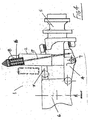
- Fig. 1 there is illustrated one side of an independent wheel suspension system according to the invention, indicated generally by the reference numeral 1, the other side of the system, which is located at an opposite side of the vehicle, being similar.
- the suspension system 1 incorporates a hydrostrut, hydraulic suspension actuator or hydro-pneumatic spring 2.
- the suspension system incorporates an upper control arm 3 and a lower control arm 4 to locate a wheel carrier 5 with respect to a vehicle body 6.
- the hydro-pneumatic spring 2 is connected at its upper end to the vehicle body 6 by an articulated joint 8 and at its lower end 7 to the lower control arm 4. It will be understood that this type of suspension system is shown for the purpose of illustration only and that the invention may be used in conjunction with many different types of suspension system.
- the hydro-pneumatic spring 2 is under compression and provides the suspension force tending to extend the suspended wheel downwardly away from the vehicle body.
- the hydro-pneumatic spring 2 comprises an inner cylinder 9, an inner end of which is slidable within an outer cylinder 10.
- the inner cylinder 9 has an upper chamber containing a variable volume of gas 11 above a separator piston 12.
- the remaining volume 13 of inner cylinder 9 below the separator piston 12 forms a lower chamber which is filled with oil and communicates with an oil-filled outer cylinder volume 14 through a damper orifice 15.
- a compensating spring 16 is located internally of the inner cylinder 9 within the lower chamber below the separator piston 12.
- the compensating spring 16 free length and stiffness may be chosen to give a hydro-pneumatic spring force which decreases gradually from a suitable load level such as the static load value to zero at full rebound, as shown in Fig. 9.
- the upper control arm 3 has an inner end connected by an articulating joint 40 with the vehicle body 6.
- An outer end of the upper control arm 3 is connected by an articulating joint 41 with the wheel carrier 5 which is a wheel hub on which a wheel (not shown) is mounted.
- An inner end of the lower control arm 4 is mounted by an articulating joint 42 on the vehicle body 6.
- An outer end of the lower control arm 4 is connected to the wheel carrier 5 by an articulating joint 43.
- a check strap 17 is provided which serves to limit the extension of the hydro-pneumatic spring 2.
- the check strap 17 is located between the vehicle body 6 and the lower control arm 4.
- the compensating spring 16 is in this case located externally of the hydro-pneumatic spring 2 and in series with the check strap 17.
- the force in the compensating spring 16 counteracts the residual force in the hydro-pneumatic spring 2.
- the compensating spring 16 free length and stiffness may be chosen to give a resultant spring force which decreases gradually from a suitable load level such as the static load value to zero at full rebound as shown in Fig. 9.
- a suspension actuator or strut 18 which is mounted between the body at 8 and the lower control arm 4 at 7, is separate from the hydro-pneumatic spring element 19.
- the strut 18 has a piston 20 slidable within an associated cylinder 22.
- An oil chamber filled with an oil volume 14 is formed between an inner bore of the cylinder 22 and the piston 20.
- the hydro-pneumatic spring 19 is separated into chamber with a gas volume 11 and an associated chamber with oil volume 13 by a separator membrane or piston 12.
- the oil volume 13 communicates with the oil volume 14 in the suspension actuator or strut 18 through damping orifice 15.
- the compensating spring 16 is internal to the hydro-pneumatic spring element 19 and acts to reduce the force exerted by the gas on the oil as the gas volume increases towards its maximum value in precisely the same manner as in the embodiment illustrated in Fig. 3.
- FIG. 7 there is shown schematically another embodiment 60 which is largely similar to that of Fig. 6 and like parts are assigned the same reference numerals.
- the compensating spring 16 is located in the suspension strut 18 within the cylinder 22 beneath the piston 20.
- the strut piston 20 comes into contact with the compensating spring 16 as the suspension moves into rebound and the force in the compensating spring 16 counteracts the residual force in the suspension strut 18.
- Fig. 8 there is shown schematically another suspension system 70 in which parts similar to those described previously are assigned the same reference numerals.
- the suspension strut 18 is a double acting hydraulic ram separate from the hydro-pneumatic spring element 19 and the compensating spring 16 is a second hydro-pneumatic spring element connected to a rod end volume 21 of the suspension strut 18 which forms a second oil chamber in the cylinder between the piston 20 and an outer end of the cylinder 22 and acts to reduce the force exerted by the suspension strut 18 as it approaches full extension.
- the compensating spring 16 has a gas volume 30 and an oil volume 31 separated by a separator membrane or piston 12, the oil volume 31 being connected to the rod end volume 21 of the suspension strut 18.
- hydro-pneumatic spring 2 or strut 18, when used in an independent suspension system of the type shown in Figs. 1 and 4, may be mounted between the vehicle body 6 and either the upper control arm 3 or lower control arm 4.
Abstract
Description
- This invention relates to hydro-pneumatic springs and in particular to hydro-pneumatic springs used in vehicle suspension systems.
- A hydro-pneumatic spring uses hydraulic fluid to transmit force to a variable volume gas chamber which acts as a spring. Hydro-pneumatic suspension systems for vehicles offer a number of advantages which include a rise in spring rate as the spring is compressed into bump and the possibility of adding additional features such as integral damping, variable damping, variable ride height, and load compensation. The non-linear spring characteristic, while advantageous as the spring is compressed towards the full bump position, creates a problem as the spring is extended towards the full rebound position because at full rebound, there is usually a large residual force remaining in the spring. This has an adverse effect on vehicle roll when cornering.
- The present invention is directed towards overcoming this problem.
- Patent Specification Nos. US 6135434 and JP 61046702 disclose hydro-pneumatic suspension elements which incorporate a spring which opposes the force exerted by the hydro-pneumatic spring as it approaches full extension in rebound.
- According to the invention, there is provided a suspension system for a vehicle, including means for supporting a wheel on a vehicle body, said wheel support means including a hydro-pneumatic spring, a compensating spring being provided which is associated with the hydro-pneumatic spring said compensating spring means being operable to act in opposition to the force exerted by the hydro-pneumatic spring as said hydro-pneumatic spring approaches full extension, the hydro-pneumatic spring having an oil chamber and an associated gas chamber with a separator piston or membrane therebetween characterised in that the compensating spring means is located in the oil chamber such that as the hydro-pneumatic spring extends into rebound the separator piston will compress the compensating spring means, the compensating spring means acting to reduce the force exerted by the separator piston or membrane on the oil in the oil chamber
- In one embodiment of the invention there is provided a suspension system for a vehicle, including:
- an upper control arm,
- a lower control arm,
- said control arms for supporting a wheel assembly on a body of the vehicle,
- each control arm having an inner end and an outer end,
- the inner end being connected by an articulated joint to the vehicle body,
- the outer end being connected by an articulated joint to the wheel assembly,
- a hydro-pneumatic spring having an upper end and a lower end,
- the upper end being attached to the vehicle body,
- the lower end being attached to one of said upper and lower control arms,
- a compensating spring means which is operable as said hydro-pneumatic spring approaches full extension to act in opposition to the force exerted by the hydro-pneumatic spring.
- In one embodiment, the compensating spring comprises an elastic element of solid material such as metal or rubber. The compensating spring may conveniently be provided by a coil spring.
- In another embodiment the hydro-pneumatic spring has a suspension actuator which is separate from but operably connected to a hydro-pneumatic element, the suspension actuator having two parts, namely a piston which is slidably mounted within an associated cylinder, one part for connection to the vehicle body and the other part for connection to the wheel support, the hydro-pneumatic element having a chamber containing oil and a chamber containing a gas separated by a separator membrane of piston, an oil chamber within the cylinder formed between an inner end of a bore of the cylinder and the piston, said oil chamber in the cylinder communicating with the oil chamber of the hydro-pneumatic element through a damping orifice.
- The invention will be more clearly understood by the following description of some embodiments thereof, given by way of example only, with reference to the accompanying drawings, in which:-
- Fig. 1 is an elevational view illustrating the general arrangement of an independent wheel suspension system incorporating a hydro-pneumatic spring according to the invention,
- Fig. 2 is a plan view of the independent suspension system of Fig. 1,
- Fig. 3 is a sectional elevational view of a hydro-pneumatic spring of the independent suspension system which incorporates a compensating spring in the form of an internal coil spring,
- Fig. 4 is a view similar to Fig. 1 showing the general arrangement of an independent wheel suspension system incorporating a hydro-pneumatic spring and an associated compensating spring according to a second embodiment of the invention, the compensating spring being mounted externally of the hydro-pneumatic spring and in series with a check strap which limits the extension of the hydro-pneumatic spring,
- Fig. 5 is an elevational view of the independent suspension system of Fig. 4,
- Fig. 6 is a schematic illustration of another hydro-pneumatic spring arrangement showing an arrangement in which a suspension actuator is separate from the hydro-pneumatic spring element and the compensating spring is internal to the hydro-pneumatic spring element and acts to reduce the force exerted by the gas on the oil as the gas volume increases towards its maximum value,
- Fig. 7 is a schematic illustration of another hydro-pneumatic spring arrangement showing an arrangement in which the suspension actuator is separate from the hydro-pneumatic spring element and a compensating spring is internal to the suspension actuator and acts to reduce the force exerted by the suspension actuator as it approaches full extension,
- Fig. 8 is a schematic illustration of another hydro-pneumatic spring arrangement showing an arrangement in which the suspension actuator is a double-acting hydraulic ram separate from the hydro-pneumatic spring element and the compensating spring is a second hydro-pneumatic spring element connected to the rod end of the suspension actuator and acts to reduce the force exerted by the suspension actuator as it approaches full extension, and
- Fig. 9 is a graph illustrating strut characteristics of a hydro-pneumatic spring of the invention.
- Referring to the drawings, and initially to Fig. 1 thereof, there is illustrated one side of an independent wheel suspension system according to the invention, indicated generally by the reference numeral 1, the other side of the system, which is located at an opposite side of the vehicle, being similar. The suspension system 1 incorporates a hydrostrut, hydraulic suspension actuator or hydro-
pneumatic spring 2. In this case, the suspension system incorporates anupper control arm 3 and alower control arm 4 to locate awheel carrier 5 with respect to avehicle body 6. The hydro-pneumatic spring 2 is connected at its upper end to thevehicle body 6 by an articulatedjoint 8 and at itslower end 7 to thelower control arm 4. It will be understood that this type of suspension system is shown for the purpose of illustration only and that the invention may be used in conjunction with many different types of suspension system. The hydro-pneumatic spring 2 is under compression and provides the suspension force tending to extend the suspended wheel downwardly away from the vehicle body. - Referring to Fig. 3, there is shown a sectional view of the hydro-
pneumatic spring 2 according to the invention. The hydro-pneumatic spring 2 comprises aninner cylinder 9, an inner end of which is slidable within anouter cylinder 10. Theinner cylinder 9 has an upper chamber containing a variable volume ofgas 11 above aseparator piston 12. Theremaining volume 13 ofinner cylinder 9 below theseparator piston 12 forms a lower chamber which is filled with oil and communicates with an oil-filledouter cylinder volume 14 through adamper orifice 15. It will be noted that in this embodiment of the invention, a compensatingspring 16 is located internally of theinner cylinder 9 within the lower chamber below theseparator piston 12. As the hydro-pneumatic spring 2 extends into rebound, theseparator piston 12 comes into contact with the compensatingspring 16 and begins to compress it. This has the effect of reducing the force exerted by theseparator piston 12 on the oil in the hydro-pneumatic spring 2. The compensatingspring 16 free length and stiffness may be chosen to give a hydro-pneumatic spring force which decreases gradually from a suitable load level such as the static load value to zero at full rebound, as shown in Fig. 9. - The
upper control arm 3, has an inner end connected by an articulatingjoint 40 with thevehicle body 6. An outer end of theupper control arm 3 is connected by an articulatingjoint 41 with thewheel carrier 5 which is a wheel hub on which a wheel (not shown) is mounted. An inner end of thelower control arm 4 is mounted by an articulatingjoint 42 on thevehicle body 6. An outer end of thelower control arm 4 is connected to thewheel carrier 5 by an articulatingjoint 43. - Referring now to Figs. 4 and 5, there is shown another suspension system which is largely similar to the suspension system shown in Fig. 1 and like parts are assigned the same reference numerals. In this case, a
check strap 17 is provided which serves to limit the extension of the hydro-pneumatic spring 2. Thecheck strap 17 is located between thevehicle body 6 and thelower control arm 4. It will be noted that the compensatingspring 16 is in this case located externally of the hydro-pneumatic spring 2 and in series with thecheck strap 17. As the hydro-pneumatic spring 2 extends into rebound, thecheck strap 17 becomes taut and starts to compress the compensatingspring 16. The force in the compensatingspring 16 counteracts the residual force in the hydro-pneumatic spring 2. The compensatingspring 16 free length and stiffness may be chosen to give a resultant spring force which decreases gradually from a suitable load level such as the static load value to zero at full rebound as shown in Fig. 9. - Referring now to Fig. 6, there is shown schematically another construction of
suspension system 50 in which parts similar to those described previously are assigned the same reference numerals. In this case, a suspension actuator orstrut 18, which is mounted between the body at 8 and thelower control arm 4 at 7, is separate from the hydro-pneumatic spring element 19. Thestrut 18 has apiston 20 slidable within an associatedcylinder 22. An oil chamber filled with anoil volume 14 is formed between an inner bore of thecylinder 22 and thepiston 20. The hydro-pneumatic spring 19 is separated into chamber with agas volume 11 and an associated chamber withoil volume 13 by a separator membrane orpiston 12. Theoil volume 13 communicates with theoil volume 14 in the suspension actuator or strut 18 through dampingorifice 15. The compensatingspring 16 is internal to the hydro-pneumatic spring element 19 and acts to reduce the force exerted by the gas on the oil as the gas volume increases towards its maximum value in precisely the same manner as in the embodiment illustrated in Fig. 3. - Referring to Fig. 7, there is shown schematically another
embodiment 60 which is largely similar to that of Fig. 6 and like parts are assigned the same reference numerals. However, in this case, the compensatingspring 16 is located in thesuspension strut 18 within thecylinder 22 beneath thepiston 20. Thestrut piston 20 comes into contact with the compensatingspring 16 as the suspension moves into rebound and the force in the compensatingspring 16 counteracts the residual force in thesuspension strut 18. - Referring now to Fig. 8, there is shown schematically another
suspension system 70 in which parts similar to those described previously are assigned the same reference numerals. In this case, thesuspension strut 18 is a double acting hydraulic ram separate from the hydro-pneumatic spring element 19 and the compensatingspring 16 is a second hydro-pneumatic spring element connected to arod end volume 21 of thesuspension strut 18 which forms a second oil chamber in the cylinder between thepiston 20 and an outer end of thecylinder 22 and acts to reduce the force exerted by thesuspension strut 18 as it approaches full extension. The compensatingspring 16 has a gas volume 30 and anoil volume 31 separated by a separator membrane orpiston 12, theoil volume 31 being connected to therod end volume 21 of thesuspension strut 18. - It will be appreciated that the hydro-
pneumatic spring 2 or strut 18, when used in an independent suspension system of the type shown in Figs. 1 and 4, may be mounted between thevehicle body 6 and either theupper control arm 3 orlower control arm 4. - The invention is not limited to the embodiments hereinbefore described which may be varied in both construction and detail within the scope of the appended claims.
Claims (5)
- A suspension system (1) for a vehicle, including means (2, 3, 4, 5) for supporting a wheel on a vehicle body (6), said wheel support means (2, 3, 4, 5) including a hydro-pneumatic spring (2), a compensating spring means (16) being provided which is associated with the hydro-pneumatic spring (2), said compensating spring means (16) being operable to act in opposition to the force exerted by the hydro-pneumatic spring (2) as said hydro-pneumatic spring (2) approaches full extension, the hydro-pneumatic spring (2) having an oil chamber (13) and an associated gas chamber (11) with a separator piston (12) or membrane therebetween, characterised in that the compensating spring means (16) is located in the oil chamber (13) such that as the hydro-pneumatic spring (2) extends into rebound the separator piston (10) will compress the compensating spring means (16), the spring means (16) acting to reduce the force exerted by the separator piston (12) or membrane on the oil in the oil chamber (13).
- A suspension system (1) as claimed in claim 1, including:an upper control arm (3),a lower control arm (4),said control arms (3, 4) for supporting a wheel assembly on a body (6) of the vehicle,each control arm (3, 4) having an inner end and an outer end,the inner end being connected by an articulated joint (40, 42) to the vehicle body (6),the outer end being connected by an articulated joint (41, 43) to the wheel assembly (5),a hydro-pneumatic spring (2) having an upper end and a lower end,the upper end being attached to the vehicle body (6),the lower end being attached to one of said upper and lower control arms (3, 4)a compensating spring means (16) which is operable as said hydro-pneumatic spring (2) approaches full extension to act in opposition to the force exerted by the hydro-pneumatic spring (2).
- A suspension system (1) as claimed in claim 1 or 2 wherein the compensating spring comprises an elastic element of solid material.
- A suspension system (1) as claimed in any preceding claim wherein the compensating spring is provided by a coil spring (16).
- A suspension system (50) as claimed in any preceding claim wherein the hydro-pneumatic spring (19) has a suspension actuator (18) which is separate from but operably connected to a hydro-pneumatic element (19), the suspension actuator (18) having two parts, namely a piston (20) which is slidably mounted within an associated cylinder (22), one part (20, 22) for connection to the vehicle body (6) and the other part (20, 22) for connection to the wheel support (3, 4), the hydro-pneumatic element (19) having a chamber (11) containing oil and a chamber (13) containing a gas separated by a separator membrane (12) or piston, an oil chamber (14) within the cylinder (22) formed between an inner end of a bore of the cylinder (22) and the piston (20), said oil chamber (14) in the cylinder (22) communicating with the oil chamber (13) of the hydro-pneumatic element (19) through a damping orifice (15).
Applications Claiming Priority (2)
| Application Number | Priority Date | Filing Date | Title |
|---|---|---|---|
| IE20010125 | 2001-02-09 | ||
| IE20010125 | 2001-02-09 |
Publications (3)
| Publication Number | Publication Date |
|---|---|
| EP1231085A2 EP1231085A2 (en) | 2002-08-14 |
| EP1231085A3 EP1231085A3 (en) | 2004-01-07 |
| EP1231085B1 true EP1231085B1 (en) | 2007-04-25 |
Family
ID=11042733
Family Applications (1)
| Application Number | Title | Priority Date | Filing Date |
|---|---|---|---|
| EP02394020A Expired - Lifetime EP1231085B1 (en) | 2001-02-09 | 2002-02-11 | Hydro-pneumatic suspension system |
Country Status (4)
| Country | Link |
|---|---|
| US (5) | US20020109327A1 (en) |
| EP (1) | EP1231085B1 (en) |
| AT (1) | ATE360543T1 (en) |
| DE (1) | DE60219708T2 (en) |
Families Citing this family (20)
| Publication number | Priority date | Publication date | Assignee | Title |
|---|---|---|---|---|
| DE10231376B3 (en) * | 2002-07-11 | 2004-01-15 | Daimlerchrysler Ag | Vehicle axle with integrated trailing arms and mounting brackets |
| US7083163B2 (en) * | 2003-09-19 | 2006-08-01 | Tenneco Automotive Operating Company Inc. | Booster with spring to adapt air spring pressure for load dependent shock absorber |
| DE202004005623U1 (en) | 2004-04-08 | 2005-08-11 | Hemscheidt Fahrwerktechnik Gmbh & Co. Kg | Suspension and damping device for motor vehicles |
| US8151953B2 (en) * | 2004-04-08 | 2012-04-10 | Samsung Electronics Co., Ltd. | Suspension and damping device for motor vehicles |
| US20100116608A1 (en) * | 2004-04-08 | 2010-05-13 | Hemscheidt Fahrwerktechnik Gmbh & Co. Kg | Suspension and damping device for motor vehicles |
| US20060021833A1 (en) * | 2004-04-08 | 2006-02-02 | Hemscheidt Fahrwerktechnik Gmbh & Co. Kg | Suspension and damping device for motor vehicles |
| US7383914B2 (en) * | 2004-12-23 | 2008-06-10 | Cnh America Llc | Apparatus and method for reducing shear loading on elements connecting an axle and a chassis of a vehicle |
| DE202005011439U1 (en) * | 2005-07-18 | 2006-11-23 | Hemscheidt Fahrwerktechnik Gmbh & Co. Kg | Suspension device for motor vehicles |
| FR2894184A1 (en) * | 2005-12-05 | 2007-06-08 | Peugeot Citroen Automobiles Sa | DEVICE FORMING A STOP TO RELIEVE A SUSPENSION OF A VEHICLE, IN PARTICULAR A MOTOR VEHICLE |
| US7954792B2 (en) | 2008-02-22 | 2011-06-07 | Axletech International IP Holdings, LLC. | Strut assembly with air spring |
| SE532525C2 (en) | 2008-06-13 | 2010-02-16 | Stroemsholmen Ab | Hydropneumatic suspension unit |
| SE533002C2 (en) * | 2008-10-20 | 2010-06-08 | Bae Systems Haegglunds Ab | Wheel suspension for wheeled vehicles |
| CN102287472B (en) * | 2011-08-09 | 2012-10-03 | 中国汽车工程研究院股份有限公司 | Series single-cylinder magnet-rheological hydro-pneumatic spring |
| FR2988453A1 (en) * | 2012-03-22 | 2013-09-27 | Peugeot Citroen Automobiles Sa | Hydraulic shock absorber for use in car, has offset compensating chamber that comprises remote trigger stop that is utilized for slowing down floating piston when shock absorber arrives in relaxation position |
| US9193242B2 (en) * | 2013-09-01 | 2015-11-24 | Saber Sohrabi | Air shock absorber with smart suspension system with height adjustment without losing comfort and safety |
| US9507037B2 (en) * | 2013-09-20 | 2016-11-29 | Pgs Geophysical As | Air-spring compensation in a piston-type marine vibrator |
| CN105059074B (en) * | 2015-09-08 | 2018-02-02 | 北京航天发射技术研究所 | suspension limiter, suspension system and vehicle with overload protection function |
| KR101997114B1 (en) * | 2017-11-17 | 2019-10-17 | 동원정밀 주식회사 | Suspension system of cylinder type for vehicle |
| US10828955B1 (en) * | 2018-06-29 | 2020-11-10 | Zoox, Inc. | Vehicle suspension system with remote actuation |
| CN110356181A (en) * | 2019-07-17 | 2019-10-22 | 北京航天发射技术研究所 | A kind of big stroke independent suspension system on super-heavy load chassis |
Family Cites Families (33)
| Publication number | Priority date | Publication date | Assignee | Title |
|---|---|---|---|---|
| US2522323A (en) * | 1944-08-28 | 1950-09-12 | Monroe Auto Equipment Co | Shock absorber seal structure |
| GB883161A (en) * | 1959-05-13 | 1961-11-22 | Volvo Ab | Improvements in hydropneumatic suspension and damping devices for vehicles |
| FR1256427A (en) * | 1959-05-13 | 1961-03-17 | Volvo Ab | Hydropneumatic suspension and damping device for vehicles |
| FR1239452A (en) * | 1959-07-17 | 1960-08-26 | Device for correcting the attitude of an oleopneumatic suspension | |
| US3162432A (en) * | 1963-03-27 | 1964-12-22 | Hughes Tool Co | Oleo strut |
| US3743109A (en) * | 1972-02-03 | 1973-07-03 | Pullman Inc | Hydraulic cushion device for railway vehicles |
| JPS50125418A (en) * | 1974-03-19 | 1975-10-02 | ||
| US3966223A (en) * | 1974-11-08 | 1976-06-29 | Carr James P | Vehicle suspension |
| US3972551A (en) * | 1975-06-04 | 1976-08-03 | General Motors Corporation | Telescoping energy absorber for vehicle bumpers and method of assembly |
| FR2473144A1 (en) * | 1980-01-04 | 1981-07-10 | Fournales France Sarl | COMBINED SHOCK AND SUSPENSION DEVICE FOR VEHICLE |
| DE3174727D1 (en) * | 1980-11-25 | 1986-07-03 | Bayerische Motoren Werke Ag | Suspension system for vehicles |
| AU553238B2 (en) * | 1983-09-26 | 1986-07-10 | Nhk Spring Co. Ltd. | Vehicle hydropneumatic suspension |
| FR2557515B1 (en) * | 1983-12-28 | 1986-05-16 | Citroen Sa | VARIABLE GROUND GUARD SUSPENSION AND FOLLOWING STOPPERS |
| US4807860A (en) * | 1984-06-28 | 1989-02-28 | Simons Stephen W | Motorcycle front fork anti-cavity damping system |
| JPS6146702A (en) * | 1984-08-10 | 1986-03-07 | Toyota Motor Corp | Suspension strut bar device |
| JPS62258207A (en) * | 1986-04-30 | 1987-11-10 | Sumio Sugawara | Combined hydraulic cylinder device |
| DE3824611A1 (en) * | 1988-07-20 | 1990-01-25 | Bayerische Motoren Werke Ag | SPRING-DAMPER SYSTEM FOR VEHICLES |
| JPH02299914A (en) * | 1989-05-16 | 1990-12-12 | Shoichi Nomoto | Wheel suspension device |
| DE4014466A1 (en) * | 1990-05-07 | 1991-11-14 | Bosch Gmbh Robert | VEHICLE SUSPENSION |
| US5570286A (en) * | 1993-12-23 | 1996-10-29 | Lord Corporation | Regenerative system including an energy transformer which requires no external power source to drive same |
| JP3485276B2 (en) * | 1994-03-28 | 2004-01-13 | 富士重工業株式会社 | Vehicle suspension |
| GB2300892A (en) * | 1995-05-16 | 1996-11-20 | Lotus Car | A damper for a vehicle suspension system |
| FI107963B (en) * | 1995-06-20 | 2001-10-31 | Instrumentarium Oy | infrared Radiator |
| US5836541A (en) * | 1997-03-05 | 1998-11-17 | Pham; Roger N. C. | Easily-convertible fixed-wing roadable aircraft |
| US5810130A (en) * | 1997-03-14 | 1998-09-22 | General Motors Corporation | Suspension damper with rebound cut-off |
| US5984060A (en) * | 1997-08-25 | 1999-11-16 | General Motors Corporation | Monotube strut assembly |
| US6260832B1 (en) * | 1997-12-17 | 2001-07-17 | Marzocchi S.P.A. | Shock absorber with adjustable compression and rebound |
| US6213261B1 (en) * | 1998-01-14 | 2001-04-10 | Mannesmann Sachs Ag | Hydropneumatic spring |
| US6135434A (en) * | 1998-02-03 | 2000-10-24 | Fox Factory, Inc. | Shock absorber with positive and negative gas spring chambers |
| US6311962B1 (en) * | 1998-02-03 | 2001-11-06 | Fox Factory, Inc. | Shock absorber with external air cylinder spring |
| US6036201A (en) * | 1998-02-23 | 2000-03-14 | General Dynamics Land Systems | Adjustable vehicle suspension |
| GB2347395B (en) * | 1999-03-04 | 2002-07-31 | Rover Group | Vehicle suspension dampers |
| DE10016641C2 (en) * | 2000-04-04 | 2002-06-13 | Daimler Chrysler Ag | Vibration damper with stop |
-
2002
- 2002-02-11 US US10/071,083 patent/US20020109327A1/en not_active Abandoned
- 2002-02-11 EP EP02394020A patent/EP1231085B1/en not_active Expired - Lifetime
- 2002-02-11 DE DE60219708T patent/DE60219708T2/en not_active Expired - Lifetime
- 2002-02-11 AT AT02394020T patent/ATE360543T1/en not_active IP Right Cessation
-
2004
- 2004-07-06 US US10/883,774 patent/US20040232606A1/en not_active Abandoned
-
2007
- 2007-01-17 US US11/653,831 patent/US20070132163A1/en not_active Abandoned
-
2009
- 2009-07-24 US US12/509,058 patent/US20100156012A1/en not_active Abandoned
-
2013
- 2013-01-18 US US13/744,721 patent/US20130127132A1/en not_active Abandoned
Also Published As
| Publication number | Publication date |
|---|---|
| DE60219708D1 (en) | 2007-06-06 |
| EP1231085A2 (en) | 2002-08-14 |
| DE60219708T2 (en) | 2007-12-27 |
| US20020109327A1 (en) | 2002-08-15 |
| US20070132163A1 (en) | 2007-06-14 |
| EP1231085A3 (en) | 2004-01-07 |
| US20040232606A1 (en) | 2004-11-25 |
| ATE360543T1 (en) | 2007-05-15 |
| US20130127132A1 (en) | 2013-05-23 |
| US20100156012A1 (en) | 2010-06-24 |
Similar Documents
| Publication | Publication Date | Title |
|---|---|---|
| US20130127132A1 (en) | Hydro-pneumatic suspension system | |
| EP1664578B1 (en) | Stroke dependent bypass | |
| US8256749B2 (en) | Strut assembly with air spring | |
| JP3538364B2 (en) | shock absorber | |
| CA1287069C (en) | Side load compensating air suspension | |
| US4607861A (en) | Hydraulic stabilizing system for vehicle suspension | |
| EP1259742B1 (en) | Compressible fluid strut | |
| CA2398595A1 (en) | Shock absorber with air pressure adjustable damping | |
| JPS63159119A (en) | Suspension system and fluid cylinder device | |
| EP2892740B1 (en) | An air spring with a linearized spring rate | |
| WO2005032860A2 (en) | Booster with spring to adapt air spring pressure for load dependent shock absorber | |
| US4903984A (en) | Suspension device | |
| WO2005032861A2 (en) | Booster to adapt air spring pressure for fdd shock absorber | |
| US6988599B2 (en) | Compressible fluid strut | |
| US20040119250A1 (en) | Spring arrangement including a spring and shock absorber assembly | |
| IE20020093A1 (en) | Hydro-pneumatic suspension system | |
| US8087646B2 (en) | Hydropneumatic suspension with load-dependent damping control | |
| US10118456B2 (en) | Load leveling emulsion suspension system | |
| US20230067276A1 (en) | Shock absorber | |
| JPS5841398Y2 (en) | Cartridge shock absorber | |
| CA2267553C (en) | Progressive air spring | |
| JP2001063336A (en) | Suspension device |
Legal Events
| Date | Code | Title | Description |
|---|---|---|---|
| PUAI | Public reference made under article 153(3) epc to a published international application that has entered the european phase |
Free format text: ORIGINAL CODE: 0009012 |
|
| AK | Designated contracting states |
Kind code of ref document: A2 Designated state(s): AT BE CH CY DE DK ES FI FR GB GR IE IT LI LU MC NL PT SE TR |
|
| AX | Request for extension of the european patent |
Free format text: AL;LT;LV;MK;RO;SI |
|
| PUAL | Search report despatched |
Free format text: ORIGINAL CODE: 0009013 |
|
| AK | Designated contracting states |
Kind code of ref document: A3 Designated state(s): AT BE CH CY DE DK ES FI FR GB GR IE IT LI LU MC NL PT SE TR |
|
| AX | Request for extension of the european patent |
Extension state: AL LT LV MK RO SI |
|
| AKX | Designation fees paid | ||
| REG | Reference to a national code |
Ref country code: DE Ref legal event code: 8566 |
|
| 17P | Request for examination filed |
Effective date: 20040922 |
|
| RBV | Designated contracting states (corrected) |
Designated state(s): AT BE CH CY DE DK ES FI FR GB GR IE IT LI LU MC NL PT SE TR |
|
| 17Q | First examination report despatched |
Effective date: 20041229 |
|
| GRAP | Despatch of communication of intention to grant a patent |
Free format text: ORIGINAL CODE: EPIDOSNIGR1 |
|
| GRAS | Grant fee paid |
Free format text: ORIGINAL CODE: EPIDOSNIGR3 |
|
| GRAA | (expected) grant |
Free format text: ORIGINAL CODE: 0009210 |
|
| AK | Designated contracting states |
Kind code of ref document: B1 Designated state(s): AT BE CH CY DE DK ES FI FR GB GR IE IT LI LU MC NL PT SE TR |
|
| PG25 | Lapsed in a contracting state [announced via postgrant information from national office to epo] |
Ref country code: LI Free format text: LAPSE BECAUSE OF FAILURE TO SUBMIT A TRANSLATION OF THE DESCRIPTION OR TO PAY THE FEE WITHIN THE PRESCRIBED TIME-LIMIT Effective date: 20070425 Ref country code: FI Free format text: LAPSE BECAUSE OF FAILURE TO SUBMIT A TRANSLATION OF THE DESCRIPTION OR TO PAY THE FEE WITHIN THE PRESCRIBED TIME-LIMIT Effective date: 20070425 Ref country code: CH Free format text: LAPSE BECAUSE OF FAILURE TO SUBMIT A TRANSLATION OF THE DESCRIPTION OR TO PAY THE FEE WITHIN THE PRESCRIBED TIME-LIMIT Effective date: 20070425 |
|
| REG | Reference to a national code |
Ref country code: GB Ref legal event code: FG4D |
|
| REG | Reference to a national code |
Ref country code: IE Ref legal event code: FG4D |
|
| REG | Reference to a national code |
Ref country code: CH Ref legal event code: EP |
|
| REF | Corresponds to: |
Ref document number: 60219708 Country of ref document: DE Date of ref document: 20070606 Kind code of ref document: P |
|
| PG25 | Lapsed in a contracting state [announced via postgrant information from national office to epo] |
Ref country code: SE Free format text: LAPSE BECAUSE OF FAILURE TO SUBMIT A TRANSLATION OF THE DESCRIPTION OR TO PAY THE FEE WITHIN THE PRESCRIBED TIME-LIMIT Effective date: 20070725 |
|
| PG25 | Lapsed in a contracting state [announced via postgrant information from national office to epo] |
Ref country code: ES Free format text: LAPSE BECAUSE OF FAILURE TO SUBMIT A TRANSLATION OF THE DESCRIPTION OR TO PAY THE FEE WITHIN THE PRESCRIBED TIME-LIMIT Effective date: 20070805 |
|
| PG25 | Lapsed in a contracting state [announced via postgrant information from national office to epo] |
Ref country code: PT Free format text: LAPSE BECAUSE OF FAILURE TO SUBMIT A TRANSLATION OF THE DESCRIPTION OR TO PAY THE FEE WITHIN THE PRESCRIBED TIME-LIMIT Effective date: 20070925 |
|
| REG | Reference to a national code |
Ref country code: CH Ref legal event code: PL |
|
| NLV1 | Nl: lapsed or annulled due to failure to fulfill the requirements of art. 29p and 29m of the patents act | ||
| ET | Fr: translation filed | ||
| PG25 | Lapsed in a contracting state [announced via postgrant information from national office to epo] |
Ref country code: AT Free format text: LAPSE BECAUSE OF FAILURE TO SUBMIT A TRANSLATION OF THE DESCRIPTION OR TO PAY THE FEE WITHIN THE PRESCRIBED TIME-LIMIT Effective date: 20070425 |
|
| PG25 | Lapsed in a contracting state [announced via postgrant information from national office to epo] |
Ref country code: BE Free format text: LAPSE BECAUSE OF FAILURE TO SUBMIT A TRANSLATION OF THE DESCRIPTION OR TO PAY THE FEE WITHIN THE PRESCRIBED TIME-LIMIT Effective date: 20070425 |
|
| PG25 | Lapsed in a contracting state [announced via postgrant information from national office to epo] |
Ref country code: NL Free format text: LAPSE BECAUSE OF FAILURE TO SUBMIT A TRANSLATION OF THE DESCRIPTION OR TO PAY THE FEE WITHIN THE PRESCRIBED TIME-LIMIT Effective date: 20070425 |
|
| PLBE | No opposition filed within time limit |
Free format text: ORIGINAL CODE: 0009261 |
|
| STAA | Information on the status of an ep patent application or granted ep patent |
Free format text: STATUS: NO OPPOSITION FILED WITHIN TIME LIMIT |
|
| 26N | No opposition filed |
Effective date: 20080128 |
|
| PG25 | Lapsed in a contracting state [announced via postgrant information from national office to epo] |
Ref country code: IT Free format text: LAPSE BECAUSE OF FAILURE TO SUBMIT A TRANSLATION OF THE DESCRIPTION OR TO PAY THE FEE WITHIN THE PRESCRIBED TIME-LIMIT Effective date: 20070425 Ref country code: GR Free format text: LAPSE BECAUSE OF FAILURE TO SUBMIT A TRANSLATION OF THE DESCRIPTION OR TO PAY THE FEE WITHIN THE PRESCRIBED TIME-LIMIT Effective date: 20070726 |
|
| PG25 | Lapsed in a contracting state [announced via postgrant information from national office to epo] |
Ref country code: MC Free format text: LAPSE BECAUSE OF NON-PAYMENT OF DUE FEES Effective date: 20080228 |
|
| PG25 | Lapsed in a contracting state [announced via postgrant information from national office to epo] |
Ref country code: CY Free format text: LAPSE BECAUSE OF FAILURE TO SUBMIT A TRANSLATION OF THE DESCRIPTION OR TO PAY THE FEE WITHIN THE PRESCRIBED TIME-LIMIT Effective date: 20070425 |
|
| PG25 | Lapsed in a contracting state [announced via postgrant information from national office to epo] |
Ref country code: DK Free format text: LAPSE BECAUSE OF FAILURE TO SUBMIT A TRANSLATION OF THE DESCRIPTION OR TO PAY THE FEE WITHIN THE PRESCRIBED TIME-LIMIT Effective date: 20070425 |
|
| PG25 | Lapsed in a contracting state [announced via postgrant information from national office to epo] |
Ref country code: LU Free format text: LAPSE BECAUSE OF NON-PAYMENT OF DUE FEES Effective date: 20080211 |
|
| PG25 | Lapsed in a contracting state [announced via postgrant information from national office to epo] |
Ref country code: TR Free format text: LAPSE BECAUSE OF FAILURE TO SUBMIT A TRANSLATION OF THE DESCRIPTION OR TO PAY THE FEE WITHIN THE PRESCRIBED TIME-LIMIT Effective date: 20070425 |
|
| REG | Reference to a national code |
Ref country code: FR Ref legal event code: PLFP Year of fee payment: 14 |
|
| PGFP | Annual fee paid to national office [announced via postgrant information from national office to epo] |
Ref country code: IE Payment date: 20150213 Year of fee payment: 14 Ref country code: DE Payment date: 20150226 Year of fee payment: 14 |
|
| PGFP | Annual fee paid to national office [announced via postgrant information from national office to epo] |
Ref country code: FR Payment date: 20150225 Year of fee payment: 14 |
|
| REG | Reference to a national code |
Ref country code: DE Ref legal event code: R119 Ref document number: 60219708 Country of ref document: DE |
|
| REG | Reference to a national code |
Ref country code: FR Ref legal event code: ST Effective date: 20161028 |
|
| REG | Reference to a national code |
Ref country code: IE Ref legal event code: MM4A |
|
| PG25 | Lapsed in a contracting state [announced via postgrant information from national office to epo] |
Ref country code: DE Free format text: LAPSE BECAUSE OF NON-PAYMENT OF DUE FEES Effective date: 20160901 Ref country code: IE Free format text: LAPSE BECAUSE OF NON-PAYMENT OF DUE FEES Effective date: 20160211 Ref country code: FR Free format text: LAPSE BECAUSE OF NON-PAYMENT OF DUE FEES Effective date: 20160229 |
|
| PGFP | Annual fee paid to national office [announced via postgrant information from national office to epo] |
Ref country code: GB Payment date: 20170228 Year of fee payment: 16 |
|
| GBPC | Gb: european patent ceased through non-payment of renewal fee |
Effective date: 20180211 |
|
| PG25 | Lapsed in a contracting state [announced via postgrant information from national office to epo] |
Ref country code: GB Free format text: LAPSE BECAUSE OF NON-PAYMENT OF DUE FEES Effective date: 20180211 |