EP1663441B1 - Filteranordnung mit abgedichtetem, magnetisch gekoppeltem reinigungskopfantrieb - Google Patents
Filteranordnung mit abgedichtetem, magnetisch gekoppeltem reinigungskopfantrieb Download PDFInfo
- Publication number
- EP1663441B1 EP1663441B1 EP04782846A EP04782846A EP1663441B1 EP 1663441 B1 EP1663441 B1 EP 1663441B1 EP 04782846 A EP04782846 A EP 04782846A EP 04782846 A EP04782846 A EP 04782846A EP 1663441 B1 EP1663441 B1 EP 1663441B1
- Authority
- EP
- European Patent Office
- Prior art keywords
- tube
- cleaning head
- sealed tube
- magnet
- filter assembly
- Prior art date
- Legal status (The legal status is an assumption and is not a legal conclusion. Google has not performed a legal analysis and makes no representation as to the accuracy of the status listed.)
- Expired - Lifetime
Links
- 238000004140 cleaning Methods 0.000 title claims abstract description 160
- 239000000463 material Substances 0.000 claims abstract description 31
- 238000000034 method Methods 0.000 claims abstract description 30
- 230000008569 process Effects 0.000 claims abstract description 30
- 239000012530 fluid Substances 0.000 claims description 12
- 238000003825 pressing Methods 0.000 abstract description 3
- 125000006850 spacer group Chemical group 0.000 description 12
- 229920003023 plastic Polymers 0.000 description 9
- 230000000712 assembly Effects 0.000 description 6
- 238000000429 assembly Methods 0.000 description 6
- 239000007788 liquid Substances 0.000 description 5
- 238000006073 displacement reaction Methods 0.000 description 4
- 238000010926 purge Methods 0.000 description 4
- 230000000295 complement effect Effects 0.000 description 3
- 239000002184 metal Substances 0.000 description 3
- 239000007787 solid Substances 0.000 description 3
- 239000011800 void material Substances 0.000 description 3
- 239000011148 porous material Substances 0.000 description 2
- 229910000619 316 stainless steel Inorganic materials 0.000 description 1
- 229910001369 Brass Inorganic materials 0.000 description 1
- 229920004943 Delrin® Polymers 0.000 description 1
- 230000005355 Hall effect Effects 0.000 description 1
- 235000014676 Phragmites communis Nutrition 0.000 description 1
- 125000000218 acetic acid group Chemical group C(C)(=O)* 0.000 description 1
- 230000009471 action Effects 0.000 description 1
- 239000010951 brass Substances 0.000 description 1
- 239000000919 ceramic Substances 0.000 description 1
- 230000008859 change Effects 0.000 description 1
- 238000010276 construction Methods 0.000 description 1
- 230000008030 elimination Effects 0.000 description 1
- 238000003379 elimination reaction Methods 0.000 description 1
- 229920006351 engineering plastic Polymers 0.000 description 1
- 238000009434 installation Methods 0.000 description 1
- 239000000314 lubricant Substances 0.000 description 1
- 239000000696 magnetic material Substances 0.000 description 1
- 238000012423 maintenance Methods 0.000 description 1
- 238000004519 manufacturing process Methods 0.000 description 1
- 230000013011 mating Effects 0.000 description 1
- 230000007246 mechanism Effects 0.000 description 1
- 230000035699 permeability Effects 0.000 description 1
- 239000011347 resin Substances 0.000 description 1
- 229920005989 resin Polymers 0.000 description 1
- 238000000926 separation method Methods 0.000 description 1
- 230000003068 static effect Effects 0.000 description 1
Images


Classifications
-
- B—PERFORMING OPERATIONS; TRANSPORTING
- B01—PHYSICAL OR CHEMICAL PROCESSES OR APPARATUS IN GENERAL
- B01D—SEPARATION
- B01D29/00—Filters with filtering elements stationary during filtration, e.g. pressure or suction filters, not covered by groups B01D24/00 - B01D27/00; Filtering elements therefor
- B01D29/11—Filters with filtering elements stationary during filtration, e.g. pressure or suction filters, not covered by groups B01D24/00 - B01D27/00; Filtering elements therefor with bag, cage, hose, tube, sleeve or like filtering elements
- B01D29/117—Filters with filtering elements stationary during filtration, e.g. pressure or suction filters, not covered by groups B01D24/00 - B01D27/00; Filtering elements therefor with bag, cage, hose, tube, sleeve or like filtering elements arranged for outward flow filtration
- B01D29/118—Filters with filtering elements stationary during filtration, e.g. pressure or suction filters, not covered by groups B01D24/00 - B01D27/00; Filtering elements therefor with bag, cage, hose, tube, sleeve or like filtering elements arranged for outward flow filtration open-ended
-
- B—PERFORMING OPERATIONS; TRANSPORTING
- B01—PHYSICAL OR CHEMICAL PROCESSES OR APPARATUS IN GENERAL
- B01D—SEPARATION
- B01D29/00—Filters with filtering elements stationary during filtration, e.g. pressure or suction filters, not covered by groups B01D24/00 - B01D27/00; Filtering elements therefor
- B01D29/62—Regenerating the filter material in the filter
- B01D29/64—Regenerating the filter material in the filter by scrapers, brushes, nozzles, or the like, acting on the cake side of the filtering element
- B01D29/6469—Regenerating the filter material in the filter by scrapers, brushes, nozzles, or the like, acting on the cake side of the filtering element scrapers
- B01D29/6484—Regenerating the filter material in the filter by scrapers, brushes, nozzles, or the like, acting on the cake side of the filtering element scrapers with a translatory movement with respect to the filtering element
-
- B—PERFORMING OPERATIONS; TRANSPORTING
- B01—PHYSICAL OR CHEMICAL PROCESSES OR APPARATUS IN GENERAL
- B01D—SEPARATION
- B01D2201/00—Details relating to filtering apparatus
- B01D2201/30—Filter housing constructions
- B01D2201/301—Details of removable closures, lids, caps, filter heads
Definitions
- This invention relates generally to a filter assembly for processing a liquid-state industrial process stream and, more particularly, to a filter assembly with a cleaning head with an actuator that is sealed and magnetically coupled to the cleaning head.
- Filter assemblies are used in industrial facilities to selectively remove material from process streams. Filter assemblies are used to both remove undesirable contaminates from process streams and to extract desirable material out of the process streams. Two such filter assemblies are disclosed in the Applicants' Assignees' U.S. Patents No. 5,198,111 , FILTER WITH RECIPROCATING CLEANING UNIT, issued March 30, 1993 and No. 5,527,462 , FILTER WITH AXIALLY MOVABLE WIPER, issued June 18, 1996.
- each of the above-referenced filter assemblies includes an elongated, cylindrically shaped housing. Internal to the housing there is a sleeve shaped filter element.
- the process stream to be filtered is introduced into the center of the filter element, usually through the top of the housing.
- the process stream is filtered as it passes from the inside to the outside of the filter member.
- the filtered process stream exits the filter assembly through an opening in the housing.
- the removed material builds up on the inner wall of the filter element. If allowed to remain in place, the material will, over time, first impede and then possibly block fluid flow through the filter assembly. Therefore, it is a common practice to further provide the filter assembly with a cleaning head. This cleaning head moves longitudinally up and down through the filter element to scrape off the material that adheres to the element. Typically, the removed material is allowed to flow through the bottom of the filter element and out through an opening in the bottom of the housing.
- U.S. Patent No. 5,198,111 discloses a filter assembly wherein the cleaning head is mounted to a threaded shaft that extends longitudinally axially through the hosing and filter element. A motor mounted to the housing rotates the shaft so as to cause the longitudinal displacement of the cleaning head.
- U.S. Patent No. 5,527,462 discloses a filter assembly wherein the cleaning head is mounted to the end of a piston rod that extends down from the top of the housing into the filter element. The opposed end of the piston rod is disposed in a cylinder attached to the top of the housing. A fluid, such as compressed air, is applied to the cylinder in order to cause the extension/retraction of the piston rod and cleaning head through the filter element.
- One disadvantage associated with providing a filter assembly with a screw type cleaning head actuator is that the actuator has components that come into contact with the process stream. Steps must be taken to ensure that the upline components that drive the moving components are not exposed to the process stream. For example, it is necessary to ensure that there is a liquid-tight seal around the opening through which the screw shaft enters the housing. A similar seal must be provided around the opening where the piston of the above-described linear actuator enters the housing. It should be understood that fluid typically enters the housing under a significant amount of pressure, for example 150 psi. In order to successfully perform the filter process, it may be necessary to repetitively actuate the cleaning head.
- the filter assembly of this invention includes a cleaning head with a sealed actuator.
- the actuator includes an actuator tube disposed in the assembly housing.
- a piston formed of magnets, is disposed is the actuator tube.
- the cleaning head is disposed over the actuator tube. Magnets associated with the cleaning head couple the head to the piston even though the actuator tube separates the two components.
- the cleaning head of the filter assembly of this invention is displaced up and down in the filter housing by selectively supplying a pressurized gas or liquid to the opposed ends of the actuator tube.
- pressurized air is employed. The air causes the piston to move longitudinally through the actuator tube. Since the cleaning head is magnetically coupled to the piston, the longitudinal movement of the piston causes the like displacement of the cleaning head.
- the filter assembly of this invention is constructed so that only the cleaning head and the complementary magnet carrier to which it is attached are the moving components exposed to the process stream.
- the actuator tube seals the components that force the movement of the cleaning head, the piston.
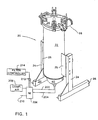
- Figure 1 is a perspective view of the filter assembly of this invention
- Figure 2 is a cross-sectional view of the basic components of the filter assembly of this invention.
- Figure 3 is a cross-sectional view of the bottom cone
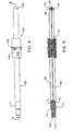
- Figure 4 is a plan view of the actuator tube and carrier subassembly of this invention.
- Figure 5 is a cross-sectional view of the actuator tube and carrier subassembly taken along line 5-5 of Figure 4 ;
- Figure 6 is a perspective view of the actuator tube bottom cap
- Figure 7 is a perspective view of the piston
- Figure 8 is a cross-sectional view of the piston wherein the piston is shown disposed over the air tube and encased within the actuator tube;
- Figure 9 is a diagrammatic illustration of how the magnets integral with the piston and carrier assembly are arranged according to the polarities of the magnets, the spacers between the magnets as well as the tubing of the carrier assembly are not illustrated. Also, the illustration only depicts the magnets on one side of the piston and carrier assembly, the arrangement on the second side is understood to mirror the illustrated arrangement;
- Figure 10 is a perspective view of the carrier
- Figure 11 is an exploded view of the carrier
- Figure 12 is a cross-sectional view of the carrier wherein the carrier is shown disposed over the actuator tube;
- Figure 13 is a top plane view of the cleaning head
- Figure 14 is a cross-sectional view of the cleaning head taken along line 14-14 of Figure 13 ;
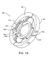
- Figure 15 is a perspective view of the cleaning head
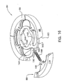
- Figure 16 is a partially exploded view of the cleaning head
- Figure 17 is a perspective view of the cleaning blade
- Figure 18 is a cross-sectional view of the cleaning blade taken along line 18-18 of Figure 17 ;
- Figure 19 is a longitudinal cross-sectional view of the cleaning blade.
- FIGS 1 and 2 illustrate the basic features of the filter assembly 20 of this invention.
- the filter assembly 20 includes a generally cylindrical housing 22.
- a pair of opposed legs 24 hold the housing 22 above ground level.
- Tabs 25 that extend from opposed sides of housing 22 connect the housing to the legs 24.
- the top end of the housing 22 is open.
- a lid 28 that is hingedly attached to housing 22 selectively covers the top opening.
- a set of locking clamps 30 releasably hold the lid 28 over the open end of the housing 22.
- Each clamp 30 has a U-bolt 32 that engages over a separate tab 34 integral with a lip 36 that extends around the opening end of the housing 22. The engagement of the U-bolts 32 over the tabs 34 is what holds the lid 28 over the housing 22.
- One source of clamps 30 is the Model 374 manufactured by De-Sta-Co Industries of Birmingham, Michigan.
- An O-ring 37 disposed in a groove in the upper exposed face of lip 36 provides a liquid-tight seal between the interface of housing 22 and lid 28 (groove not identified).
- a small bore 38 extends through the center axis of lid 28. Bore 38 functions as a vent.
- bottom end of housing 22 is also open.
- a bottom cone 40 is welded or otherwise permanently secured to the bottom end of housing 22. As seen by reference to Figures 2 and 3 , it is noted that bottom cone 40 is formed with a lip 41 that is disposed within the bottom end of housing 22. Bottom cone 40 is further formed to have a tubularly shaped outlet fitting 39 that extends laterally away from the base or bottom end of the cone.
- Bottom cone 40 is further shaped so that the section of the cone immediately below lip 41 and opposite the side of the cone from which fitting 39 extends downwardly from the inner perimeter of lip 41, cone section 42, has a constant diameter.
- the end section of the bottom cone 40, cone end section 44, is semispherical in shape.
- the cone end section 44 is the portion of the bottom cone 40 from which the outlet fitting 39 extends.
- a tear-drop shaped boss 45 extends upwardly from the inner wall of the cone end section 44. Boss 45 is positioned so that the wide diameter section of the boss is centered on the longitudinal axis of the housing 22 and bottom cone 40. The narrow diameter pointed end of boss 45 is directed towards, and is in line with, the longitudinal axis of the outlet fitting 39.
- a filter element 46 is disposed in the enclosed space defined by housing 22, lid 28 and bottom cone 40.
- the filter element includes a base ring 48 with an L-shaped cross-sectional profile from which a filter member 50 extends.
- one particular filter member 50 includes a number of longitudinally extending metal ribs that are spaced a small distance apart from each other. The ribs extend circumferentially around the base member. Spaced apart metal annular ribs extend around the outer surface of the longitudinally extending ribs. The interstitial gaps between the ribs of the filter member 50 are the pores through which the process liquid flows.
- a top ring 51 similar in shape to bottom ring 48, extends around the top of the filter member 50.
- U-shaped handles 52 one partially shown, extend upwardly from top ring 51. Handles 52 facilitate the installation and removal of the filter element 46 from housing 22.
- the compressor assembly consists of a retainer ring 53 to which a number of upwardly extending legs 54 are attached, (one leg 54 shown).
- the lid 28 When lid 28 is closed, the inner surface of the lid bears against the adjacent ends of the legs 54. The lid 28 thus forces the legs 54 and, therefore, retainer ring 53, against filter element top ring 51. The engagement of these components is what holds the filter element 46 in position in housing 22.
- Filter element base ring 48 is formed with an outwardly beveled surface 55 around the outer perimeter of the bottom of the ring.
- Retainer ring 53 is formed with a similar beveled surface 56.
- First and second O-rings 57 seat in the spaces adjacent the beveled ring surfaces 55 and 56.
- one of the 0-rings 57 provides a liquid-tight seal between the filter element base ring 48 and the adjacent inner wall of the housing 22.
- the second O-ring 57 provides a liquid-tight seal between the retainer ring 53 and the housing 22 at the top of the filter element 46.
- An inlet fitting 58 is connected to housing 22 and opens into the housing above retainer ring 53.
- An outlet fitting 60 is connected to the housing 22 and extends from an opening located above where the filter element base ring 48 is located.
- the cleaning head assembly 62 Internal to the filter element 46 is a cleaning head assembly 62 for removing trapped material off the filter member 50.
- the cleaning head assembly 62 includes a generally disk shaped cleaning head 64 that moves up and down through the filter element 46.
- a number of cleaning blades 66 are attached to the cleaning head around the outer perimeter of the head. The cleaning blades 66 abut the adjacent inner surface of the filter member 50 to scrape the trapped material off the filter member.
- the cleaning head 64 is slidably mounted over an actuator tube 68 that extends longitudinally axially through the housing 22 and the filter element 46.
- a pneumatically actuated piston 70 is disposed inside the actuator tube 68. cleaning head 64 is magnetically coupled to piston 70.
- the longitudinal displacement of the piston 70 in the actuator tube 68 results in the like longitudinal movement of the cleaning head 64 through the housing and against the filter member 50.
- Actuator tube 68 is formed of a metal that will not react with the contents of the process stream and that is non-magnetic, has a high magnetic permeability and low, preferably zero, magnetic susceptibility.
- One such material from which actuator tube 68 may be formed is 316 stainless steel.
- the actuator tube 68 extends upwardly from a solid, generally cylindrical, bottom cap 71 that is fixedly secured to the bottom cone 40.
- Bottom cap 71 now described by reference to Figures 5 and 6 , is formed of the same material from which the actuator tube 68 is formed.
- the bottom cap 71 is shaped to have a relatively narrow diameter stem section 72.
- a wide diameter head 74 extends coaxially with the stem section 72 and is a single piece with the stem section.
- Two bores 76 and 77 extend longitudinally through the bottom cap 71.
- a first bore, bore 76 in Figure 6 extends to an opening centered around the longitudinal axis of the bottom cap 71 on the top of the head 74 (bore opening not identified).
- the second bore, bore 77 extends to an opening in the top of the head that is offset from the center axis (bore opening not identified).
- the bottom cap stem section 72 is welded or otherwise secured in a bore 75 formed in bottom cone boss 45. More particularly, the bottom cap 71 is fitted to the boss 45 so that the bottom cap and, therefore, the actuator tube 68, extend longitudinally axially through the bottom cone 40 and the housing 22.
- An O-ring 79 seated in a groove 80 in the bottom cap stem section 72 provides a liquid-tight seal between the bottom cap and the adjacent inner wall of the boss 45.
- the end of bottom cap stem section 72 extends a short distance beyond the outer surface of the bottom cone 40.
- Actuator tube 68 is welded or otherwise secured to the bottom cap head 74.
- the bottom cap 71 is formed with a small, reduced diameter recess 86 around the outer perimeter of the head 74. The end of the actuator tube 68 seats in the recess 86.
- an air tube 90 extends longitudinally axially through actuator tube 68.
- One end of air tube 90 is mounted in the bottom cap head opening to which bore 76 extends.
- Air tube 90 is formed from the same material from which the actuator tube 68 is formed.
- End cap 92 covers the open ends of the actuator tube 68 and air tube 90.
- End cap 92 which is generally frusto-conical in shape, is formed from the same material from which the actuator tube 68 is formed.
- the outer perimeter of the end cap 92 is formed with a recess (not identified) in which the adjacent end of the actuator tube 68 nests.
- the end cap 92 is also formed with a closed-end inlet bore 96 that extends upwardly from the base of the cap and that extends along the longitudinal axis of the cap.
- End cap 92 is further formed to have at least one outlet bore 98 (two shown) that extends from the base of the inlet bore 96.
- the outlet bore 98 extends diagonally away from the inlet bore 96.
- Outlet bore 98 thus opens into a portion of the base of the end cap 92 that subtends the annular space defined by the inner wall of actuator tube 68 and the outer wall of air tube 90.
- bores 96 and 98 provide a fluid flow path from the air tube 90 into the top of the actuator tube 68.
- Piston 70 is formed to have two opposed cylindrically shaped end caps 102 made of plastic.
- One specific plastic from which end caps 102 can be manufactured is polythyleneterphtalate plastic with solid lubricant sold under the trademark ERTALYTE TX by Quadrant Engineering Plastic Products of Tielt, Belgium and Reading, Pennsylvania.
- Sandwiched between end caps 102 are four ring-shaped magnets 104 and five ring-shaped 106 spacers formed of a non-magnetic material such as a ceramic. More specifically, there is a spacer 106 located between each pair of magnets 104. There is also a spacer 106 located between each end cap 102 and the magnet 104 adjacent the end cap.
- magnets 104 are arranged so that faces of adjacent magnets are of the same polarity.
- a tube-shaped tie rod 108 formed of brass holds the end caps 102, magnets 104 and spacers 106 together. Tie rod 108 extends through the center openings of magnets 104 and spacers 106 (center opening of magnets and spacers not identified). One end of the tie rod 108 engages threading formed in the bore that extends through one of the end caps 102. The second end of the tie rod 108 engages threading formed in the bore that extends through the second end cap 102. The interior diameter of the tie rod 108 is approximately 0.010 inches greater than that of the enclosed air tube 90.
- the end caps 102 are dimensioned to closely fit in the annular space between the actuator tube 68 and air tube 90.
- the end caps 102 thus function as the bearing elements of the piston 70.
- Lip seals 110 are seated in grooves 112 formed along the outer perimeter of the end caps 102.
- One seal 110 is fitted to each end cap 102.
- the lip seals 110 thus function as the seal members between the piston 70 and the adjacent inner wall of the actuator tube 68.
- An O-ring 114 seats in a counterbore 116 around the open end of each bore that extends through each end cap 102.
- the O-rings 114 function as the seals between the piston 70 and the air tube 90.
- Magnets 104 and spacers 106 are dimensioned to have diameters that are slightly less than the interior diameter of the surrounding actuator tube 68. In one version of the invention, these components are dimensioned so that the width of the annular gap between the actuator tube 68 and the magnets 104 and spacers 106 is approximately 0.015 inches. This separation prevents the magnets and spacers from galling the interior of the actuator tube 68.
- a generally sleeve-shaped carrier assembly 120 magnetically couples the cleaning head 64 to piston 70.
- the carrier assembly 120 is slidably disposed over the actuator tube 68 and has an elongated outer tube 122 formed from the same material from which actuator tube 68 is formed.
- each bearing 124 has a smooth surfaced outer wall 126 that abuts the adjacent inner surface of outer tube 122.
- the inner end of each bearing 124 is formed to have a number of inwardly directed, arcuately spaced apart teeth 128 that are arranged in a circumferential pattern.
- the inner surfaces of teeth 128 are the surfaces of carrier assembly 120 that actually physically abut the outer surface of actuator tube 68.
- Snap rings 130 disposed in grooves 131 formed in the inner surface of the outer tube 122 hold bearings 124, as well as the other components internal to the outer tube, in the outer tube.
- Each carrier retainer 136 extends from the outer surface of the adjacent inner tube end to the inner surface of the surrounding outer tube 122.
- O-rings 138 and 139 are mounted in grooves formed, respectively, in the outer and inner surfaces of each carrier retainer 136.
- O-ring 138 forms a seal between the associated carrier retainer 136 and the adjacent outer surface of inner tube 134.
- O-ring 139 forms a seal between the associated carrier retainer 136 and the adjacent inner surface of outer tube 122.
- the magnets 132 are disposed in the enclosed annular space defined by outer and inner tubes 122 and 134, respectively, and carrier retainers 136. Ring-shaped spacers 140 separate adjacent magnets 132. One spacer 140 is also located between each carrier retainer 136 and the adjacent magnet 132.
- magnets 132 are arranged so that the faces of the same polarity are adjacent each other. Magnets 104 and 132 are collectively arranged so that when the carrier assembly 120 is fitted over the actuator tube 68 and piston 70, the faces of each magnet 132 are of opposite polarity than the coplanar faces of the corresponding coplanar magnet 104.
- this filter assembly 20 of this invention are assembled so that inner tube 134 of carrier assembly 120 has a diameter that is approximately 0.125 inches greater than the diameter of the enclosed actuator tube 68.
- the only components of the carrier assembly 120 that abut the actuator tube 68 are the teeth 128 of the bearings 124.
- the process stream is able to flow through the interstitial gaps between the bearing teeth 128 at one end of the carrier assembly 120, through the annular gap between the actuator tube 68 and inner tube 134 and out through the interstitial gaps between the bearing teeth 128 at the opposed end of the carrier assembly 120.
- This arrangement prevents components of the process stream, such as solids that would otherwise be caught by filter member 50, from being trapped between the actuator tube 68 and the carrier assembly 120. If material was allowed to be trapped between the actuator tube 68 and the carrier assembly 120, one or both of the components could be damaged.
- the cleaning head 64 is in the form of a flat disk.
- the cleaning head 64 is shaped to have an inner ring 142 and an outer ring 143.
- Four equangularly spaced apart webs 144 connect the inner and outer rings 142 and 143, respectively, together.
- the openings in the head 64 between rings 142 and 143 and webs 144 allow the process fluid to flow through the head.
- the cleaning head 64 is seated between a lip 146 and a set of equangularly spaced apart keys 148 that extend circumferentially around the carrier assembly outer tube 122, as seen best in Figure 10 .
- Both the lip 146 and keys 148 are formed integrally with the outer tube 122.
- the lip 146 extends continuously around the outer tube 122 adjacent the mid-section of the tube.
- Keys 148 are located a small distance, the thickness of cleaning head 64, above lip 146.
- the outer perimeter of the center of each key 148 is formed to have a small circularly shaped groove 150.
- the outer perimeter of lip 146 is formed is formed to have four spaced apart grooves 152. Each groove 152 is aligned with a separate one of the key grooves 150.
- cleaning head inner ring 142 is formed with a set of inwardly directed angularly spaced apart tabs 154.
- cleaning head 64 and outer tube 122 are dimensioned so that the cleaning head tabs 154 can side over the tube 122 in the spaces adjacent the tube keys 148.
- Tabs 154 are further dimensioned so as to have inner edges 156 that are dimensioned to facilitate the close slip fitting of the cleaning head 64 of the carrier assembly outer tube 122.
- the cleaning head 64 is releasably mounted to the carrier assembly 120 by slip-fitting the head over outer tube 122. Movement of the cleaning head 64 is stopped by the abutment of tabs 154 against outer tube lip 146. The cleaning head 64 is then rotated so that tabs 154 seat in the annular gaps between the lip 146 and keys 148 of the outer tube 122. More particularly, the cleaning head is rotated until an opening 158 formed in the inner ring 142 goes into registration with the key and lip grooves 150 and 152, respectively, of the carrier assembly 120. A lock pin 160 is seated in opening 158. The lock pin 160 has a stem 162 that extends through opening 158 and seats in the key and lip grooves 150 and 152, respectively. The lock pin 160 thus holds the cleaning head 64 to the carrier assembly 120.
- Lock pin 160 is further formed to have a head 164 that has a larger diameter and is coaxial with stem 162. Head 164 thus prevents the lock pin 160 from passing fully through opening 158. Trunions 166 extend perpendicularly from the base of the head 164. A small wire cable (not illustrated) extends from one of the trunions 166 to the cleaning head 164 to hold the lock pin 160 to the cleaning head. The opposed ends of the wire, which are looped, extend around openings 169 and 170 formed, respectively, in one of the trunions 166 and the cleaning head inner ring 142.
- lock pin 160 is further formed so a slot 168 extends longitudinally partially through the head 164 from the top of the head.
- the top of the head 164 has an inwardly beveled profile. Providing the head with these features makes it possible to use the lock pin 160 as a tool for removing the cleaning blades 66 from the cleaning head 64.
- Each cleaning blade 66 is formed from a single piece of moldable plastic.
- One suitable plastic is an acetyl resin plastic sold by du Pont under the trademark DELRIN.
- the cleaning blade 66 is formed to have an arcuately shaped base 172.
- Base 172 defines the curved outer face 174 of the blade 66 that is disposed against the filter member 50.
- the side of base 172 opposite that of outer face 174 is formed to have a groove 176 that extends the length of the base.
- the cleaning blade base 172 is further formed to have opposed, substantially identically shaped, top and bottom faces 178 and 180, respectively, that extend inwardly from outer face 174.
- Base 172 is formed so that, relative to the top and bottom edges of the outer face 174, the top and bottom faces 178 and 180, respectively, are inwardly angled.
- the edges defined by the interfaces of outer face 174 to the top face 178 and the bottom face 180 are the edge surfaces that scrape trapped material off the filter member 50.
- Cleaning blade base 172 is further formed to have opposed end faces 181 and 182. Each end face 181 extends from the top face 178 to the bottom face.180 at one end the base.
- the base 172 is formed so that the end faces 181 and 182 are at an obtuse, non-perpendicular angle to the parallel planes of the top and bottom edge surfaces of the base. The angles of faces 181 and 182 relative to the base edge surfaces are identical.
- Each cleaning blade 66 is further formed to have two overlapping legs 183.
- the legs 183 extend inwardly from the inner face of the base 172, on opposed sides of groove 176 towards the center of the cleaning head 64.
- Each leg 183 generally has the profile of one of the head webs 144. when each cleaning blade 66 is mounted to the head, the opposed blade legs 183 extend over and under an associated one of the webs 144.
- Pins 184 one seen best in Figure 16 , that extend laterally through the opposed sides of each web 144, hold the cleaning blades 66 to the cleaning head 64.
- Each leg 183 is formed with an elongated slot 186. When a cleaning blade 66 is fitted to the head, the legs 183 are sufficiently flexible to outwardly bend as the legs move over the associated pin 184. When the pin 184 goes into registration with the associated leg slot 186, the legs 183 snap back down over the enclosed web 144 so as to result in the seating of the pin in the slot.
- a coil spring 190 outwardly biases each cleaning blade 66 relative to the cleaning head 64.
- One end of each spring 190 is seated in parallel opposed slots 192 that extend inwardly from the outer perimeter of the cleaning head outer ring 143. More particularly, the slots 192 forming each slot pair are parallel with and located on opposed sides of the longitudinal axis of a separate one of the head webs 144.
- Each spring 190 thus is located between the legs 183 of the cleaning blade 66 with which the spring is associated.
- the opposed inner faces of the legs 183 are formed with inwardly directed curved grooves 193.
- the outer end of each spring 190 abuts a spring pad 194 integral with the base 172 of the associated cleaning blade 66.
- the spring pad 194 thus extends into the base of the blade groove 176.
- the opposed inner surfaces of the cleaning blade leg 183 are formed with tapers 196 adjacent the ends of the legs.
- the tapers facilitate the snap-fitting of the legs over the associated cleaning head pin 184.
- the tapers 196 also define spaces between the cleaning head 64 and cleaning blade legs 183 in which the beveled and slotted head 164 of lock pin 160 can be wedged between the legs and the cleaning head. This allows lock pin 160 to be used as a tool for flexing the legs 183 to facilitate the removal of the cleaning blade 66 from the cleaning head 64.
- Air line 202 is connected to cap bore 76 through a counter bore 203.
- Air line 204 is connected to cap bore 77 through a counter bore 205.
- the opposed ends of air lines 202 and 204 are connected to a common manifold 206.
- Also connected to the manifold 206 is a source of compressed air 208 and a vent to atmosphere 210.
- a manifold piston (not illustrated) establishes the connection between the air lines 202 and 204 and the air source 208 and vent 210.
- air line 202 is connected to air source 208 and air line 204 is connected to the vent 210.
- air line 202 is connected to the vent 210 and air line 204 is connected to the air source 208.
- solenoid 212 The position of the manifold piston is controlled by a solenoid 212.
- the actuation of solenoid 212 is controlled by a filter controller 214.
- the filter assembly 20 of this invention is used to filter liquid state process streams.
- the process stream enters the filter assembly 20, and the center of the filter element 46, through inlet fitting 58.
- the process stream it should be understood, flows through the openings formed in the cleaning head 64. Material in the process stream, larger in size than pores of the filter member 50, are trapped by the filter member.
- the filtered process stream is discharged from the filter assembly 20 through the outlet fitting 60.
- the cleaning head assembly 62 is actuated to scrap this material off the filter member 50.
- the cleaning head assembly 62 is actuated by energizing the solenoid 212 to change the position of the piston internal to manifold 206.
- the manifold piston is set so that air line 202 is connected to the air source 208. Air line 204 and, by extension, bore 77, is vented to atmosphere. When the cleaning head 64 is in this state, the position of the manifold piston is reset to connect air line 202 and, by extension, bore 76, to the vent 210. The resetting of the manifold piston also connects air line 204, and therefore bore 77, to the air supply.
- the removed material is periodically removed from the filter assembly 20 by directing a purge flow through the assembly.
- the filtrage is flushed into the bottom cone 40 and out through the cone outlet fitting 39.
- the shape of the bottom cone 40 ensures that the purging liquid flows throughout the whole of the interior space of the bottom cone. The flowing of the purge fluid in this pattern substantially eliminates the possibility that material wall become trapped and adhere to the interior surfaces of the bottom cone 40.
- the downward movement of the cleaning head 64 also causes the cleaning blades 66 to move against filter member 50 so as to scrape the trapped material off the member.
- the cleaning blades 66 are constructed so that the blade end faces 181 and 182 are at obtuse, non-perpendicular, angles to the longitudinal axes of the blades. As depicted in Figure 15 , this construction ensures the gaps around the circumference of the cleaning head 64 and, by extension, the filter member 50, that are not covered by an edge surface of one of the cleaning blades will be covered by an edge surface of an adjacent blade. Thus, as the blades 66 wear, there will still be a blade edge surface pressing against each circumferential section of the filter member 50 so as to scrape material off the whole of the member.
- Spring 190 ensures that, as the base 172 of the cleaning blade 66 with which the spring is associated wears, the edge surfaces of the blade continue to press against the filter member 50.
- the spring pad 194 of a cleaning blade 66 performs two functions.
- the spring pad 194 serves as a surface against which the associated spring 190 bears.
- the spring pad 194 also serves as a pad that holds the portions of the base inward of the section that defines outer face 174 and the base of groove 176 together. This function is desirable because, over time, the pressing of the blade base 172 against the filter member 50 causes this outer perimeter section of the base to wear away. Eventually the material forming this section of the cleaning blade 66 can wear through to groove 176. When this occurs, spring pad 194 holds the remaining portions of the base, the portions that define the inward sections of the base bottom and top edges 178 and 180, respectively, together. Thus, spring pad 194 prevents the portions of the cleaning blade from separating while in the filter assembly 20.
- magnetic field sensors 218 and 220 it may be desirable to mount magnetic field sensors 218 and 220 to the filter housing 22.
- One sensor, sensor 218 in Figure 2 is mounted to the filter housing 22 so as to be aligned with the lowest longitudinal positions of the piston 70 and the carrier assembly 120.
- Sensor 220 is mounted to the filter housing 22 so as to be aligned with the highest longitudinal positions of the piston 70 and the carrier assembly 120.
- Sensors 218 and 220 may be Hall effect sensors or magnetically actuated switches like reed switches.
- Each sensor 218 and 220 is encased in its own bubble 222 that is magnetically shielded from the ambient environment.
- the sensors 218 and 220 are thus sensitive to the magnetic fields generated by piston magnets 104 and carrier assembly magnets 132. Sensors 218 and 220 thus, respectively, generate signals indicating when the cleaning head 64 is in, respectively, the lowest and highest position in the filter member. These signals can be used to monitor whether or not the filter assembly of this invention is functioning properly.
- the signals generated by sensors 218 and 220 can also be applied to filter controller 214. Filter controller 214, based on the cleaning head position information provided by the sensor signals, can then selectively control the energization of the solenoid 212 so as to regulate the setting of the manifold piston.
- each air line can be connected to the source of compressed air, a vent to atmosphere or sealed closed.
- air line 204 could be closed. This would leave a charge of pressurized air in air line 204, cap bore 77 and the actuator tube 68 that would hold the piston 70 in the elevated state. This would eliminate the need to continually supply pressurized air to perform this function.
- pneumatic fluid may be employed to perform this function. It should further be recognized that it may not be necessary in all versions of this invention to employ fluids to drive piston 70 up and down through the actuator tube 68.
- the piston, or at least magnets 104 may be driven up and down in the actuator tube 68 by a lead screw that, while static in position, rotates within the actuator tube 68. The mechanism used to drive this lead screw could be similar to that described in U.S. Patent No. 5,198,111 .
- the magnets 104 may be at the head of a piston rod that is disposed within the actuator tube 68. A head associated with the piston rod is contained in a piston cylinder external to housing 22 and is pneumatically or hydraulically driven.
- the particular hydraulic drive assembly could be similar to that described in U.S. Patent No. 5,527,462 .
- Still another feature of this invention is that, in some versions of the invention, multiple filter assembly housings 22 may be connected together by tabs 25. In these versions of the invention, the housings 22 support each other. Thus, an array of filter assemblies 20 of this invention can be assembled together without having to provide each assembly with its own support legs.
- each cleaning blade may, on each side, have two or more legs with members or void spaces designed to facilitate the engagement of the cleaning blade with the complementary cleaning head.
Landscapes
- Chemical & Material Sciences (AREA)
- Chemical Kinetics & Catalysis (AREA)
- Filtering Of Dispersed Particles In Gases (AREA)
- Filtration Of Liquid (AREA)
- Cleaning In General (AREA)
- Supporting Of Heads In Record-Carrier Devices (AREA)
- Separation Using Semi-Permeable Membranes (AREA)
- External Artificial Organs (AREA)
- Extrusion Moulding Of Plastics Or The Like (AREA)
Claims (21)
- Filteranordnung (20), umfassend:ein Gehäuse (22), das einen umschlossenen Raum definiert, wobei das genannte Gehäuse (22) eine Einlassöffnung (58), die in den umschlossenen Raum mündet, und eine Auslassöffnung (60) hat, die aus dem umschlossenen Raum mündet,ein Filterelement (46), das in dem umschlossenen Raum in dem genannten Gehäuse angeordnet ist, wobei das genannte Filterelement (46) in dem genannten Gehäuse (22) positioniert ist, so dass ein durch die genannte Einlassöffnung (58) in den umschlossenen Raum eingeführter Prozessstrom durch das genannte Filterelement (46) strömt, bevor er durch die genannte Auslassöffnung (60) abgelassen wird, und wobei das genannte Filterelement (46) eine Oberfläche hat, an der beim Hindurchströmen des Prozessstroms durch das genannte Filterelement (46) entferntes Material gefangen wird,einen Reinigungskopf (64), der in dem genannten umschlossenen Raum in dem genannten Gehäuse angeordnet ist und wenigstens ein Reinigungsblatt (66) hat, das zur Anlage an dem genannten Filterelement (46) positioniert ist,gekennzeichnet durch ein abgedichtetes Rohr (68) in dem umschlossenen Raum des genannten Gehäuses (22),einen ersten Magneten (104), der in dem genannten abgedichteten Rohr (68) angeordnet ist, um sich in dem genannten abgedichteten Rohr (68) zu bewegen,eine mit dem genannten abgedichteten Rohr (68) oder dem genannten ersten Magneten verbundene Stellantriebanordnung zum selektiven Bewegen des genannten ersten Magneten in dem genannten abgedichteten Rohr (68) undeinen zweiten Magneten (132), der sich in dem umschlossenen Raum in dem genannten Gehäuse (22) befindet und neben und außerhalb von dem genannten abgedichteten Rohr (68) angeordnet ist, wobei der genannte zweite Magnet (132) magnetisch mit dem genannten ersten Magneten (104) gekoppelt ist, um sich mit der Bewegung des genannten ersten Magneten (104) an dem genannten abgedichteten Rohr (68) entlang zu bewegen, und an dem genannten Reinigungskopf (64) angebracht ist, so dass sich der genannte Reinigungskopf (64) mit dem genannten zweiten Magneten (132) bewegt.
- Filteranordnung nach Anspruch 1, bei dem die genannte Stellantriebsanordnung Folgendes umfasst:eine Druckluftquelle (208) und eine Luftleitung (202), die mit der genannten Druckluftquelle (208) und dem genannten abgedichteten Rohr (68) verbunden ist.
- Filteranordnung nach Anspruch 1, bei der:das genannte abgedichtete Rohr (68) ein oberes und ein unteres Ende hat, die einander entgegengesetzt sind, und der genannte erste Magnet (104) zur Bewegung zwischen dem oberen und dem unteren Ende in dem genannten abgedichteten Rohr (68) angeordnet ist,ein Luftrohr (90) mit dem genannten abgedichteten Rohr (68) verbunden ist und in das obere Ende des genannten abgedichteten Rohrs (68) mündet,wobei die genannte Stellantriebsanordnung Folgendes aufweist:eine mit dem genannten abgedichteten Rohr (68) verbundene erste Luftleitung (202), durch die Gas zum unteren Ende des genannten abgedichteten Rohrs (68) zugeführt werden kann,eine mit dem genannten Luftrohr verbundene zweite Luftleitung (204), durch die Gas zu dem genannten Luftrohr (90) zum oberen Ende des genannten abgedichteten Rohrs (68) zugeführt werden kann,eine Druckgasquelle (208) undeine Strömungssteueranordnung (212, 214), die an einem Ende mit der genannten ersten (202) und zweiten Luftleitung (204) und an einem zweiten Ende mit der genannten Druckgasquelle (208) verbunden ist, um den Druckgasstrom zu der genannten ersten Luftleitung (202) oder der genannten zweiten Luftleitung (204) zu lenken.
- Filteranordnung nach Anspruch 3, bei der:das genannte Luftrohr (90) in dem genannten abgedichteten Rohr (68) angeordnet ist undder genannte erste Magnet (104) das genannte Luftrohr (90) wenigstens teilweise umgibt.
- Filteranordnung nach Anspruch 3, bei der:der genannte erste Magnet (104) mit einer Bohrung (116) ausgebildet ist unddas genannte Luftrohr (90) in dem genannten abgedichteten Rohr (68) angeordnet ist und so in dem genannten abgedichteten Rohr (68) positioniert ist, dass sich das genannte Luftrohr (90) durch die Bohrung (116) in dem genannten ersten Magneten (104) erstreckt.
- Filteranordnung nach Anspruch 1, bei der:das genannte Filterelement (46) das genannte abgedichtete Rohr (68) umgibt und das genannte wenigstens eine Reinigungsblatt (66) zur Anlage an der ganzen Oberfläche des genannten Filterelements (50) positioniert ist, welches das genannte abgedichtete Rohr (68) umgibt.
- Filteranordnung nach Anspruch 1, bei der:das genannte Rohr sich längs durch den umschlossenen Raum des genannten Gehäuses erstreckt, wobei das genannte Rohr sich neben der Oberfläche des genannten Filterelements (46), an der entferntes Material gefangen wird, befindet,der genannte erste Magnet (104) zur Längsbewegung in dem genannten Rohr positioniert ist,der genannte Reinigungskopf (64) zwischen dem genannten Rohr und der Oberfläche des genannten Filterelements (46), an der entferntes Material gefangen wird, angeordnet ist.
- Filteranordnung nach Anspruch 7, bei der das genannte wenigstens eine Reinigungsblatt (66) auslösbar mit dem genannten zweiten Magneten (132) verbunden ist.
- Filteranordnung nach Anspruch 7, bei der:der genannte Reinigungskopf (64) ein Körperstück aufweist, das sich zwischen dem genannten Rohr (68) und dem genannten Filterelement (46) befindet,der genannte zweite Magnet (132) auslösbar an dem genannten Körperstück angebracht ist unddas genannte wenigstens eine Reinigungsblatt (66) auslösbar am äußeren Umfang des genannten Reinigungskopfkörperstücks angebracht ist und zur Anlage an dem genannten Filterelement (46) positioniert ist.
- Filteranordnung nach Anspruch 1, bei der:das genannte Gehäuse (22) einen umschlossenen Raum definiert, wobei das genannte Gehäuse die genannte Einlassöffnung (58) in den umschlossenen Raum und die genannte Auslassöffnung (60) aus dem umschlossenen Raum hat,das genannte Filterelement (46) in dem umschlossenen Raum längs verläuft,das genannte Rohr (68) längs wenigstens teilweise durch den umschlossenen Raum verläuft und sich einwärts der Oberfläche des genannten Filterelements (46), an der entferntes Material gefangen wird, befindet, wobei das genannte Rohr (68) ein oberes und ein unteres Ende hat, die einander entgegengesetzt sind und zu dem umschlossenen Raum abgedichtet sind,ein Luftrohr (90) in dem genannten abgedichteten Rohr (68) angeordnet ist, wobei das genannte Luftrohr (90) ein oberes Ende hat, das in das obere Ende des genannten abgedichteten Rohres (68) mündend offen ist,ein Kolben (70) in dem genannten abgedichteten Rohr (68) verschiebbar zwischen dem genannten abgedichteten Rohr (68) und dem genannten Luftrohr (90) angeordnet werden kann, wobei der genannte Kolben (70) wenigstens einen genannten ersten Magneten (104) hat,eine Rohranordnung (202, 204) an einem Ende mit einer Gasquelle (208) und an einem zweiten Ende mit dem Boden des genannten abgedichteten Rohres (68) und mit dem genannten Luftrohr (90) verbunden ist, undder genannte Reinigungskopf (64) sich in dem umschlossenen Raum des genannten Gehäuses zwischen dem genannten Filterelement (46) und dem genannten abgedichteten Rohr (68) befindet, wobei der genannte Reinigungskopf (64) wenigstens einen genannten zweiten Magneten (132) hat.
- Filteranordnung nach Anspruch 10, bei der der genannte Kolben (70) das genannte Luftrohr (90) wenigstens teilweise umgibt.
- Filteranordnung nach Anspruch 10, bei der:das genannte abgedichtete Rohr (68) und das genannte Luftrohr (90) koaxial sind undder genannte Kolben (70) einschließlich des genannten wenigstens einen ersten Magneten (104) mit einer durchgehenden Bohrung (116) ausgebildet ist und der genannte Kolben (70) in dem genannten abgedichteten Rohr (68) angeordnet ist, so dass das genannte Luftrohr (90) durch die Kolbenbohrung (116) verläuft.
- Filteranordnung nach Anspruch 10, bei der:eine Endkappe (92) das obere Ende des genannten abgedichteten Rohres (68) bedeckt,das genannte Luftrohr (90) in die genannte Endkappe (92) hinein verläuft unddie genannte Endkappe (92) mit einem Fluidkommunikationsweg ausgebildet ist, der von einem oberen Ende des genannten Luftrohres (90) zum oberen Ende des genannten abgedichteten Rohres (68) verläuft.
- Filteranordnung nach Anspruch 10, bei der die genannte Luftrohranordnung (202, 204) eine erste Luftleitung (202) aufweist, die sich von einer Öffnung in den Boden des genannten abgedichteten Rohres (68) erstreckt, und eine zweite Luftleitung (204), die sich von dem genannten Luftrohr (90) erstreckt.
- Filteranordnung nach Anspruch 10, bei der der genannte Reinigungskopf (64) einen Körper aufweist, an dem der genannte wenigstens eine zweite Magnet (132) angebracht ist und an dem das genannte wenigstens eine Reinigungsblatt (66) auslösbar und beweglich angebracht ist, und der genannte Reinigungskopf (64) ein sich zwischen dem genannten Körper und dem genannten wenigstens einen Reinigungsblatt (66) erstreckendes Vorspannelement (190) zum Drängen des genannten wenigstens einen Reinigungsblatts (66) nach außen in Richtung auf das genannte Filterelement (46) aufweist.
- Filteranordnung nach Anspruch 10, bei der der genannte Reinigungskopf (64) einen Körper aufweist, an dem der genannte wenigstens eine zweite Magnet (132) auslösbar angebracht ist und an dem das genannte wenigstens eine Reinigungsblatt (66) angebracht ist.
- Filteranordnung nach Anspruch 10, bei der der genannte Reinigungskopf Folgendes aufweist:einen Träger (12), der gleitfähig auf dem genannten abgedichteten Rohr (68) angeordnet ist, und wobei der genannte wenigstens eine zweite Magnet (132) in dem genannten Träger (120) angeordnet ist, undeinen Körper, der auslösbar an dem genannten Träger befestigt ist, und wobei das genannte wenigstens eine Reinigungsblatt (66) an dem genannten Körper angebracht ist.
- Filteranordnung nach Anspruch 10, bei der der genannte Kolben (70) eine Vielzahl der genannten ersten Magnete (104) aufweist.
- Filteranordnung nach Anspruch 10, bei der der genannte Reinigungskopf (64) eine Vielzahl der genannten zweiten Magnete (132) aufweist.
- Filteranordnung nach Anspruch 1, bei der
die Filteranordnung (20) so angeordnet ist, dass der Prozessstrom durch die Einlassöffnung (58) in das Gehäuse (22) und in die Mitte des Filterelements (46) eingeführt wird,
eine Reinigungskopfanordnung (62) sich im Inneren des Filterelements (46) befindet, wobei die den Reinigungskopf (64) aufweisende Reinigungskopfanordnung (62) im Allgemeinen scheibenförmig ist und zwischen einem Innenring (142) und einem Außenring (144) Öffnungen und eine Vielzahl von Stegen (144) hat, um das Prozessfluid durch den Kopf (64) strömen zu lassen, wobei der Reinigungskopf (64) eine Vielzahl von Reinigungsblättern (66) aufweist, die um den Außenumfang des Kopfes (64) an dem Reinigungskopf angebracht sind, wobei jedes Blatt (66) eine bogenförmige Basis (172) mit einer Seite der Basis (172) gegenüber der einer Außenfläche (174) hat, wobei die Seite der Basis so ausgebildet ist, dass sie eine Nut (176) hat, die über die Länge der Basis verläuft, wobei ein Abschnitt des Außenrings (143) in der Nut (176) sitzt, wobei jedes Blatt ferner so ausgebildet ist, dass es zwei überlappende Schenkel (183) hat, wobei die Schenkel (183) sich von der Innenfläche der Basis (172) an einander gegenüberliegenden Seiten der Nut (176) einwärts in Richtung auf die Mitte des Reinigungskopfes (64) erstrecken, wobei jedes Blatt (64) von einer Schraubenfeder (190) relativ zu dem Reinigungskopf (64) auswärts vorgespannt wird. - Filteranordnung nach Anspruch 20, bei der:ein Ende der Feder (190) in einem parallelen entgegengesetzten Schlitz (192) sitzt, der von dem Außenumfang des Reinigungskopfaußenrings (143) einwärts verläuft, wobei sich die Feder (190) zwischen den Schenkeln (183) des Reinigungsblatts (66) befindet, mit dem die Feder assoziiert ist, wobei die Schenkel (183) einander gegenüberliegende Innenflächen haben, die mit einwärts gerichteten gekrümmten Nuten (176) ausgebildet sind, wodurch sie den Sitz der Feder zwischen den Schenkeln ermöglichen, wobei jedes Reinigungsblatt ferner Folgendes aufweist:einen Stift (184), der sich seitlich durch einander gegenüberliegende Seiten eines Stegs (144) streckt, wobei der Stift (184) das Reinigungsblatt (66) an dem Reinigungskopf (64) hält, wobei der Stift (184) in einem in jedem der Schenkel (183) ausgebildeten Langloch (186) sitzt, wobei die Reinigungsblattbasis (172) so ausgebildet ist, dass sie einander gegenüberliegende, im Wesentlichen identisch gestaltete obere und untere Seitenflächen (178, 180) hat, wobei die Reinigungsblattbasis (172) ferner einander entgegengesetzte Endflächen (181, 182) hat, wobei jede Endfläche an einem Ende der Basis (172) von der oberen Seitenfläche (178) zu der unteren Seitenfläche (180) verläuft, wobei die Basis (172) so ausgebildet ist, dass die Endflächen (181, 182) in einem nicht senkrechten stumpfen Winkel zu parallelen Ebenen einer oberen und einer unteren Randfläche der Basis (172) sind.
Priority Applications (2)
| Application Number | Priority Date | Filing Date | Title |
|---|---|---|---|
| EP10011498.2A EP2316555B1 (de) | 2003-09-03 | 2004-09-01 | Reinigungskopf für eine Filtervorrichtung |
| EP10011503A EP2308577B1 (de) | 2003-09-03 | 2004-09-01 | Reinigungskratzer für einen Reinigungskopf |
Applications Claiming Priority (2)
| Application Number | Priority Date | Filing Date | Title |
|---|---|---|---|
| US10/654,013 US7093721B2 (en) | 2003-09-03 | 2003-09-03 | Filter assembly with sealed, magnetically coupled cleaning head actuator |
| PCT/US2004/028430 WO2005023394A2 (en) | 2003-09-03 | 2004-09-01 | Filter assembly with sealed, magnetically coupled cleaning head actuator |
Publications (2)
| Publication Number | Publication Date |
|---|---|
| EP1663441A2 EP1663441A2 (de) | 2006-06-07 |
| EP1663441B1 true EP1663441B1 (de) | 2010-10-20 |
Family
ID=34217997
Family Applications (3)
| Application Number | Title | Priority Date | Filing Date |
|---|---|---|---|
| EP10011503A Expired - Lifetime EP2308577B1 (de) | 2003-09-03 | 2004-09-01 | Reinigungskratzer für einen Reinigungskopf |
| EP10011498.2A Expired - Lifetime EP2316555B1 (de) | 2003-09-03 | 2004-09-01 | Reinigungskopf für eine Filtervorrichtung |
| EP04782846A Expired - Lifetime EP1663441B1 (de) | 2003-09-03 | 2004-09-01 | Filteranordnung mit abgedichtetem, magnetisch gekoppeltem reinigungskopfantrieb |
Family Applications Before (2)
| Application Number | Title | Priority Date | Filing Date |
|---|---|---|---|
| EP10011503A Expired - Lifetime EP2308577B1 (de) | 2003-09-03 | 2004-09-01 | Reinigungskratzer für einen Reinigungskopf |
| EP10011498.2A Expired - Lifetime EP2316555B1 (de) | 2003-09-03 | 2004-09-01 | Reinigungskopf für eine Filtervorrichtung |
Country Status (8)
| Country | Link |
|---|---|
| US (1) | US7093721B2 (de) |
| EP (3) | EP2308577B1 (de) |
| CN (3) | CN101357277B (de) |
| AT (1) | ATE485090T1 (de) |
| BR (1) | BRPI0414080B1 (de) |
| CA (3) | CA2759240C (de) |
| DE (1) | DE602004029692D1 (de) |
| WO (1) | WO2005023394A2 (de) |
Families Citing this family (46)
| Publication number | Priority date | Publication date | Assignee | Title |
|---|---|---|---|---|
| US20070289905A1 (en) * | 2006-06-20 | 2007-12-20 | Biofuels Automation, Inc. | System for managing solution for cleaning fermentation tanks |
| US7794591B2 (en) | 2007-03-23 | 2010-09-14 | Zodiac Pool Systems, Inc. | Pool filter |
| US7815796B2 (en) | 2007-03-23 | 2010-10-19 | Zodiac Pool Systems, Inc. | Pool filter |
| US8828223B2 (en) | 2007-05-15 | 2014-09-09 | Pitco Frialator, Inc. | Continuously operating filtering apparatus |
| CA2644573C (en) * | 2007-10-05 | 2011-12-06 | David B. Nibler | Methods and apparatus for a pool treatment and water system |
| US8516661B2 (en) * | 2009-04-29 | 2013-08-27 | Zodiac Pool Systems, Inc. | Retainer band for use in fluid-handling vessels |
| SG174635A1 (en) * | 2010-03-08 | 2011-10-28 | Aalborg Ind Water Treat Pte Ltd | Self-cleaning filter module |
| CN103157318B (zh) * | 2011-12-16 | 2016-12-21 | 李云生 | 一种免拆洗长寿陶瓷滤芯净水器 |
| US9669339B2 (en) * | 2013-03-21 | 2017-06-06 | Schlumberger Technology Corporation | In-line magnetic particle filter |
| CN103230905B (zh) * | 2013-04-24 | 2015-08-12 | 孙清云 | 一种磁隅清洗装置 |
| EP3013446B1 (de) | 2013-06-26 | 2021-12-08 | Pentair Residential Filtration, LLC | Filtrationskartusche und wasserfiltrationssystem |
| US10918980B2 (en) | 2014-01-31 | 2021-02-16 | Fuji Filter Manufacturing Co., Ltd. | Filtering apparatus |
| ES2834969T3 (es) * | 2014-04-18 | 2021-06-21 | Becton Dickinson Co | Conjunto de catéter de seguridad de control sanguíneo multiuso |
| CN103931733B (zh) * | 2014-04-23 | 2015-12-30 | 昆山市富众网络科技有限公司 | 螃蟹壳酶解池的过滤装置 |
| USD755344S1 (en) | 2014-06-26 | 2016-05-03 | Pentair Residential Filtration, Llc | Filter cartridge |
| US9347494B2 (en) | 2014-07-15 | 2016-05-24 | Boss Tool Corporation | Guiding element for actuator |
| CN105435509A (zh) * | 2014-09-30 | 2016-03-30 | 上海安赐环保科技股份有限公司 | 应用于高温煤焦油净化系统的刮盘过滤装置、净化系统及净化工艺 |
| EP3215261B1 (de) | 2014-11-07 | 2021-12-15 | Genesis Technologies, LLC | Linearer kolbenaktuator |
| CN104801093B (zh) * | 2015-03-31 | 2017-02-01 | 宁波方太厨具有限公司 | 一种陶瓷滤芯自动清洗装置 |
| CA165693S (en) * | 2015-06-05 | 2017-10-02 | Donaldson Co Inc | Filter element |
| WO2017077171A1 (en) | 2015-11-03 | 2017-05-11 | Outotec (Finland) Oy | Vacuum box, belt filter, methods of using a vacuum belt filter, and filter element |
| CN105944444B (zh) * | 2016-06-15 | 2019-04-05 | 珠海格力电器股份有限公司 | 底座组件及管道式净水机 |
| NL2017218B1 (en) | 2016-07-22 | 2018-01-30 | Spiro Entpr Bv | Liquid treatment device |
| CN106512510A (zh) * | 2016-12-07 | 2017-03-22 | 杭州科百特过滤器材有限公司 | 过滤器 |
| CN108261832B (zh) * | 2016-12-30 | 2023-10-20 | 福州品行科技发展有限公司 | 一种不断流滤芯更换结构 |
| US20210106932A1 (en) * | 2017-03-27 | 2021-04-15 | Kamel Mahran Hussien Mam | Oils frequency cleaner |
| CN107648901A (zh) * | 2017-09-06 | 2018-02-02 | 安徽乐金环境科技有限公司 | 过滤器 |
| CN107497600B (zh) * | 2017-09-18 | 2024-04-12 | 深圳市杰维工业设备有限公司 | 一种动态除铁过滤设备 |
| US10773215B2 (en) * | 2018-12-21 | 2020-09-15 | Eaton Intelligent Power Limited | Self-cleaning and monitoring filtration system |
| US20220088538A1 (en) * | 2019-01-10 | 2022-03-24 | Repligen Corporation | Hollow fiber filtration systems and methods |
| US11845021B2 (en) * | 2019-05-17 | 2023-12-19 | Kx Technologies, Llc | Filter interconnect utilizing correlated magnetic actuation for downstream system function |
| CN117085381A (zh) * | 2019-08-28 | 2023-11-21 | Kx技术有限公司 | 利用由编码多磁体产生的磁性剪切力的过滤器互连件 |
| US11367320B2 (en) * | 2019-09-24 | 2022-06-21 | Caterpillar Inc. | Systems and methods for part identification |
| CN110814658B (zh) * | 2019-11-15 | 2020-10-23 | 深圳市佳鑫一帆科技有限公司 | 一种高精密度的洗板头的制作方法 |
| CN111964488B (zh) * | 2020-08-17 | 2021-11-02 | 亿利洁能(浦江)有限公司 | 一种可在线拆装滤管的防堵塞换热器 |
| US12403494B2 (en) | 2020-08-26 | 2025-09-02 | Deere & Company | Work vehicle sprayer system and method with nozzle monitoring |
| US12083543B2 (en) | 2020-08-26 | 2024-09-10 | Deere & Company | Work vehicle sprayer system and method with switching nozzle apparatus |
| US11896989B2 (en) * | 2020-08-26 | 2024-02-13 | Deere & Company | Work vehicle sprayer system and method with self-cleaning filter apparatus |
| US12330179B2 (en) | 2020-08-26 | 2025-06-17 | Deere &Company | Work vehicle sprayer system and method with pinching nozzle apparatus |
| US12343664B2 (en) * | 2021-05-05 | 2025-07-01 | Hamilton Sundstrand Corporation | Monolithic additively manufactured pump inlet housing and filter |
| CN113648693B (zh) * | 2021-07-14 | 2022-12-27 | 安徽金星钛白(集团)有限公司 | 偏钛酸贮存槽下料防堵塞用初级过滤器 |
| CN113830908B (zh) * | 2021-09-08 | 2023-04-07 | 安徽棣泽环保科技有限公司 | 基于转动式的水处理剂均匀搅拌的污水处理设备 |
| CN115350516B (zh) * | 2022-08-12 | 2024-07-19 | 安徽省农业科学院蔬菜研究所 | 一种便于废弃物清理的西瓜果汁粉的固液分离装置 |
| CN115253434B (zh) * | 2022-08-30 | 2023-06-16 | 青岛雷勒过滤科技有限公司 | 一种可对内部筛网清理的过滤器 |
| CN117138417B (zh) * | 2023-10-27 | 2024-01-26 | 新乡市新净过滤设备有限公司 | 袋式过滤器 |
| CN121651471B (zh) * | 2026-02-06 | 2026-04-10 | 陕西橘子实业有限公司 | 一种磷酸盐生产用冷却水的处理装置 |
Family Cites Families (17)
| Publication number | Priority date | Publication date | Assignee | Title |
|---|---|---|---|---|
| IL79723A (en) * | 1986-08-15 | 1990-02-09 | Drori Mordeki | Semi-automatic fluid filter |
| FI83329C (fi) * | 1988-03-31 | 1991-06-25 | Neste Oy | Foerfarande foer framstaellning av en buren polymerisationskatalysator och anordning foer anvaendning vid foerfarandet. |
| JP2551480B2 (ja) * | 1989-04-28 | 1996-11-06 | 株式会社 荒井鉄工所 | スクレーパ濾過システム |
| FR2656312B1 (fr) * | 1989-12-22 | 1993-07-23 | Elf Aquitaine | Procede de synthese de solides catalytiques de type ziegler ou de composantes solides de tels solides catalytiques en operant dans un reacteur pivotant polyfonctionnel unique. |
| US5087365A (en) * | 1990-06-14 | 1992-02-11 | Delaware Capital Formation, Inc. | Filter with rotating wiper having indexing blades |
| JPH0642931B2 (ja) | 1990-08-16 | 1994-06-08 | 孝一 荒井 | スクレーパ濾過装置 |
| GB2247187B (en) * | 1990-08-24 | 1994-04-27 | Chen Tsong Hae | Liquid filter assembly |
| US5198111A (en) | 1991-01-10 | 1993-03-30 | Delaware Capital Formation, Inc. | Filter with reciprocating cleaner unit |
| TW369545B (en) * | 1993-02-12 | 1999-09-11 | Hoechst Ag | Process for preparing cycloolefin copolymers |
| US5525701A (en) * | 1993-12-14 | 1996-06-11 | General Electric Company | Method for the manufacture of aromatic polycarbonate |
| US5527462A (en) | 1994-11-15 | 1996-06-18 | Delaware Capital Formation, Inc. | Filter with axially movable wiper |
| CN1046490C (zh) * | 1994-12-13 | 1999-11-17 | 孙同福 | 磁-滤污水净化方法及设备 |
| US5569383A (en) | 1994-12-15 | 1996-10-29 | Delaware Capital Formation, Inc. | Filter with axially and rotatably movable wiper |
| US5804072A (en) * | 1997-09-29 | 1998-09-08 | Yang; Chi-Hua | Water filter with strainer scraping means |
| IL122675A (en) * | 1997-12-18 | 2001-01-28 | Ar Kal Plastics Products 1973 | Reverse flow spin-cleaning liquid filters |
| CN2508834Y (zh) * | 2001-10-29 | 2002-09-04 | 昆山明达滤水设备有限公司 | 水处理滤水设备 |
| CA2363588C (en) | 2001-11-22 | 2010-08-03 | Jean-Pierre Racine | Self-cleaning filter |
-
2003
- 2003-09-03 US US10/654,013 patent/US7093721B2/en not_active Expired - Lifetime
-
2004
- 2004-09-01 CN CN2008102132029A patent/CN101357277B/zh not_active Expired - Lifetime
- 2004-09-01 DE DE602004029692T patent/DE602004029692D1/de not_active Expired - Lifetime
- 2004-09-01 AT AT04782846T patent/ATE485090T1/de not_active IP Right Cessation
- 2004-09-01 CA CA2759240A patent/CA2759240C/en not_active Expired - Lifetime
- 2004-09-01 EP EP10011503A patent/EP2308577B1/de not_active Expired - Lifetime
- 2004-09-01 EP EP10011498.2A patent/EP2316555B1/de not_active Expired - Lifetime
- 2004-09-01 CN CN201210105319.1A patent/CN102764532B/zh not_active Expired - Lifetime
- 2004-09-01 CN CNB2004800327056A patent/CN100421761C/zh not_active Expired - Lifetime
- 2004-09-01 BR BRPI0414080A patent/BRPI0414080B1/pt active IP Right Grant
- 2004-09-01 CA CA2536575A patent/CA2536575C/en not_active Expired - Lifetime
- 2004-09-01 EP EP04782846A patent/EP1663441B1/de not_active Expired - Lifetime
- 2004-09-01 WO PCT/US2004/028430 patent/WO2005023394A2/en not_active Ceased
- 2004-09-01 CA CA2759236A patent/CA2759236C/en not_active Expired - Lifetime
Also Published As
| Publication number | Publication date |
|---|---|
| DE602004029692D1 (de) | 2010-12-02 |
| US7093721B2 (en) | 2006-08-22 |
| EP2316555A1 (de) | 2011-05-04 |
| CN102764532B (zh) | 2015-04-22 |
| CA2759236A1 (en) | 2005-03-17 |
| BRPI0414080A (pt) | 2006-10-24 |
| ATE485090T1 (de) | 2010-11-15 |
| EP2316555B1 (de) | 2014-01-01 |
| CN101357277B (zh) | 2012-06-13 |
| CN100421761C (zh) | 2008-10-01 |
| BRPI0414080B1 (pt) | 2016-04-12 |
| EP1663441A2 (de) | 2006-06-07 |
| CA2759240C (en) | 2014-01-28 |
| EP2308577A1 (de) | 2011-04-13 |
| CA2759240A1 (en) | 2005-03-17 |
| CN1874833A (zh) | 2006-12-06 |
| CA2536575C (en) | 2012-11-20 |
| CN102764532A (zh) | 2012-11-07 |
| CN101357277A (zh) | 2009-02-04 |
| WO2005023394A3 (en) | 2005-05-12 |
| CA2536575A1 (en) | 2005-03-17 |
| US20050045537A1 (en) | 2005-03-03 |
| EP2308577B1 (de) | 2012-11-07 |
| WO2005023394A2 (en) | 2005-03-17 |
| CA2759236C (en) | 2013-07-16 |
Similar Documents
| Publication | Publication Date | Title |
|---|---|---|
| EP1663441B1 (de) | Filteranordnung mit abgedichtetem, magnetisch gekoppeltem reinigungskopfantrieb | |
| US10060553B2 (en) | Valve | |
| KR101299806B1 (ko) | 유체 필터 | |
| CA2419926C (en) | Filter assembly, filter element, and method of utilizing the same | |
| US6000417A (en) | Bi-directional magnetically-operated check valve for high-purity applications | |
| US7513372B2 (en) | Wave coil filter assembly | |
| US5527462A (en) | Filter with axially movable wiper | |
| EP0408177A1 (de) | Rückschlagventilpatronen mit kontrollierbarer Druckabdichtung | |
| WO2013066370A2 (en) | Media control valve | |
| US4846218A (en) | Check valve for liquid chromatography pumps | |
| CA2118979C (en) | Sampling pump | |
| US20060096908A1 (en) | Device for filtering fluids that are conveyed under a high presure | |
| US20150362079A1 (en) | Media Control Valve | |
| US20190076761A1 (en) | Filter assembly and wiper therefor and method of making same | |
| EP3670980A1 (de) | Mediumgetrenntes ventil | |
| US5277073A (en) | Constant pressure-loaded shaft seal | |
| US5984267A (en) | Apparatus for isolating and containing reactive medium | |
| US20020108654A1 (en) | Filter arrangement at a pressure regulator | |
| EP0831268A2 (de) | Vorrichtung zur Aufnahme und Isolierung eines reaktionsfähigen Mediums |
Legal Events
| Date | Code | Title | Description |
|---|---|---|---|
| PUAI | Public reference made under article 153(3) epc to a published international application that has entered the european phase |
Free format text: ORIGINAL CODE: 0009012 |
|
| 17P | Request for examination filed |
Effective date: 20060331 |
|
| AK | Designated contracting states |
Kind code of ref document: A2 Designated state(s): AT BE BG CH CY CZ DE DK EE ES FI FR GB GR HU IE IT LI LU MC NL PL PT RO SE SI SK TR |
|
| DAX | Request for extension of the european patent (deleted) | ||
| 17Q | First examination report despatched |
Effective date: 20080304 |
|
| GRAP | Despatch of communication of intention to grant a patent |
Free format text: ORIGINAL CODE: EPIDOSNIGR1 |
|
| GRAS | Grant fee paid |
Free format text: ORIGINAL CODE: EPIDOSNIGR3 |
|
| GRAA | (expected) grant |
Free format text: ORIGINAL CODE: 0009210 |
|
| AK | Designated contracting states |
Kind code of ref document: B1 Designated state(s): AT BE BG CH CY CZ DE DK EE ES FI FR GB GR HU IE IT LI LU MC NL PL PT RO SE SI SK TR |
|
| REG | Reference to a national code |
Ref country code: GB Ref legal event code: FG4D |
|
| REG | Reference to a national code |
Ref country code: CH Ref legal event code: EP |
|
| REG | Reference to a national code |
Ref country code: IE Ref legal event code: FG4D |
|
| RAP2 | Party data changed (patent owner data changed or rights of a patent transferred) |
Owner name: EATON LP |
|
| REF | Corresponds to: |
Ref document number: 602004029692 Country of ref document: DE Date of ref document: 20101202 Kind code of ref document: P |
|
| REG | Reference to a national code |
Ref country code: GB Ref legal event code: 732E Free format text: REGISTERED BETWEEN 20110120 AND 20110126 |
|
| REG | Reference to a national code |
Ref country code: NL Ref legal event code: VDEP Effective date: 20101020 |
|
| PG25 | Lapsed in a contracting state [announced via postgrant information from national office to epo] |
Ref country code: PT Free format text: LAPSE BECAUSE OF FAILURE TO SUBMIT A TRANSLATION OF THE DESCRIPTION OR TO PAY THE FEE WITHIN THE PRESCRIBED TIME-LIMIT Effective date: 20110221 Ref country code: BG Free format text: LAPSE BECAUSE OF FAILURE TO SUBMIT A TRANSLATION OF THE DESCRIPTION OR TO PAY THE FEE WITHIN THE PRESCRIBED TIME-LIMIT Effective date: 20110120 Ref country code: SE Free format text: LAPSE BECAUSE OF FAILURE TO SUBMIT A TRANSLATION OF THE DESCRIPTION OR TO PAY THE FEE WITHIN THE PRESCRIBED TIME-LIMIT Effective date: 20101020 Ref country code: SI Free format text: LAPSE BECAUSE OF FAILURE TO SUBMIT A TRANSLATION OF THE DESCRIPTION OR TO PAY THE FEE WITHIN THE PRESCRIBED TIME-LIMIT Effective date: 20101020 Ref country code: FI Free format text: LAPSE BECAUSE OF FAILURE TO SUBMIT A TRANSLATION OF THE DESCRIPTION OR TO PAY THE FEE WITHIN THE PRESCRIBED TIME-LIMIT Effective date: 20101020 Ref country code: NL Free format text: LAPSE BECAUSE OF FAILURE TO SUBMIT A TRANSLATION OF THE DESCRIPTION OR TO PAY THE FEE WITHIN THE PRESCRIBED TIME-LIMIT Effective date: 20101020 Ref country code: AT Free format text: LAPSE BECAUSE OF FAILURE TO SUBMIT A TRANSLATION OF THE DESCRIPTION OR TO PAY THE FEE WITHIN THE PRESCRIBED TIME-LIMIT Effective date: 20101020 |
|
| PG25 | Lapsed in a contracting state [announced via postgrant information from national office to epo] |
Ref country code: GR Free format text: LAPSE BECAUSE OF FAILURE TO SUBMIT A TRANSLATION OF THE DESCRIPTION OR TO PAY THE FEE WITHIN THE PRESCRIBED TIME-LIMIT Effective date: 20110121 Ref country code: BE Free format text: LAPSE BECAUSE OF FAILURE TO SUBMIT A TRANSLATION OF THE DESCRIPTION OR TO PAY THE FEE WITHIN THE PRESCRIBED TIME-LIMIT Effective date: 20101020 |
|
| PG25 | Lapsed in a contracting state [announced via postgrant information from national office to epo] |
Ref country code: ES Free format text: LAPSE BECAUSE OF FAILURE TO SUBMIT A TRANSLATION OF THE DESCRIPTION OR TO PAY THE FEE WITHIN THE PRESCRIBED TIME-LIMIT Effective date: 20110131 Ref country code: CZ Free format text: LAPSE BECAUSE OF FAILURE TO SUBMIT A TRANSLATION OF THE DESCRIPTION OR TO PAY THE FEE WITHIN THE PRESCRIBED TIME-LIMIT Effective date: 20101020 Ref country code: EE Free format text: LAPSE BECAUSE OF FAILURE TO SUBMIT A TRANSLATION OF THE DESCRIPTION OR TO PAY THE FEE WITHIN THE PRESCRIBED TIME-LIMIT Effective date: 20101020 |
|
| PLBE | No opposition filed within time limit |
Free format text: ORIGINAL CODE: 0009261 |
|
| STAA | Information on the status of an ep patent application or granted ep patent |
Free format text: STATUS: NO OPPOSITION FILED WITHIN TIME LIMIT |
|
| PG25 | Lapsed in a contracting state [announced via postgrant information from national office to epo] |
Ref country code: RO Free format text: LAPSE BECAUSE OF FAILURE TO SUBMIT A TRANSLATION OF THE DESCRIPTION OR TO PAY THE FEE WITHIN THE PRESCRIBED TIME-LIMIT Effective date: 20101020 Ref country code: SK Free format text: LAPSE BECAUSE OF FAILURE TO SUBMIT A TRANSLATION OF THE DESCRIPTION OR TO PAY THE FEE WITHIN THE PRESCRIBED TIME-LIMIT Effective date: 20101020 Ref country code: DK Free format text: LAPSE BECAUSE OF FAILURE TO SUBMIT A TRANSLATION OF THE DESCRIPTION OR TO PAY THE FEE WITHIN THE PRESCRIBED TIME-LIMIT Effective date: 20101020 Ref country code: PL Free format text: LAPSE BECAUSE OF FAILURE TO SUBMIT A TRANSLATION OF THE DESCRIPTION OR TO PAY THE FEE WITHIN THE PRESCRIBED TIME-LIMIT Effective date: 20101020 |
|
| 26N | No opposition filed |
Effective date: 20110721 |
|
| REG | Reference to a national code |
Ref country code: DE Ref legal event code: R097 Ref document number: 602004029692 Country of ref document: DE Effective date: 20110721 |
|
| REG | Reference to a national code |
Ref country code: DE Ref legal event code: R082 Ref document number: 602004029692 Country of ref document: DE Representative=s name: 2K PATENTANWAELTE BLASBERG KEWITZ & REICHEL, P, DE |
|
| PG25 | Lapsed in a contracting state [announced via postgrant information from national office to epo] |
Ref country code: MC Free format text: LAPSE BECAUSE OF NON-PAYMENT OF DUE FEES Effective date: 20110930 |
|
| REG | Reference to a national code |
Ref country code: CH Ref legal event code: PL |
|
| REG | Reference to a national code |
Ref country code: DE Ref legal event code: R082 Ref document number: 602004029692 Country of ref document: DE Representative=s name: 2K PATENTANWAELTE BLASBERG KEWITZ & REICHEL PA, DE Effective date: 20120319 Ref country code: DE Ref legal event code: R081 Ref document number: 602004029692 Country of ref document: DE Owner name: EATON INDUSTRIES MANUFACTURING GMBH, CH Free format text: FORMER OWNER: EATON LP, GLASGOW, GB Effective date: 20120319 Ref country code: DE Ref legal event code: R082 Ref document number: 602004029692 Country of ref document: DE Representative=s name: 2K PATENTANWAELTE BLASBERG KEWITZ & REICHEL, P, DE Effective date: 20120319 |
|
| REG | Reference to a national code |
Ref country code: IE Ref legal event code: MM4A |
|
| REG | Reference to a national code |
Ref country code: GB Ref legal event code: 732E Free format text: REGISTERED BETWEEN 20120628 AND 20120704 |
|
| PG25 | Lapsed in a contracting state [announced via postgrant information from national office to epo] |
Ref country code: IE Free format text: LAPSE BECAUSE OF NON-PAYMENT OF DUE FEES Effective date: 20110901 Ref country code: CH Free format text: LAPSE BECAUSE OF NON-PAYMENT OF DUE FEES Effective date: 20110930 Ref country code: LI Free format text: LAPSE BECAUSE OF NON-PAYMENT OF DUE FEES Effective date: 20110930 |
|
| PG25 | Lapsed in a contracting state [announced via postgrant information from national office to epo] |
Ref country code: LU Free format text: LAPSE BECAUSE OF NON-PAYMENT OF DUE FEES Effective date: 20110901 Ref country code: CY Free format text: LAPSE BECAUSE OF EXPIRATION OF PROTECTION Effective date: 20101020 |
|
| PG25 | Lapsed in a contracting state [announced via postgrant information from national office to epo] |
Ref country code: TR Free format text: LAPSE BECAUSE OF FAILURE TO SUBMIT A TRANSLATION OF THE DESCRIPTION OR TO PAY THE FEE WITHIN THE PRESCRIBED TIME-LIMIT Effective date: 20101020 |
|
| PG25 | Lapsed in a contracting state [announced via postgrant information from national office to epo] |
Ref country code: HU Free format text: LAPSE BECAUSE OF FAILURE TO SUBMIT A TRANSLATION OF THE DESCRIPTION OR TO PAY THE FEE WITHIN THE PRESCRIBED TIME-LIMIT Effective date: 20101020 |
|
| REG | Reference to a national code |
Ref country code: FR Ref legal event code: PLFP Year of fee payment: 13 |
|
| REG | Reference to a national code |
Ref country code: FR Ref legal event code: PLFP Year of fee payment: 14 |
|
| REG | Reference to a national code |
Ref country code: FR Ref legal event code: PLFP Year of fee payment: 15 |
|
| REG | Reference to a national code |
Ref country code: GB Ref legal event code: 732E Free format text: REGISTERED BETWEEN 20181115 AND 20181130 |
|
| REG | Reference to a national code |
Ref country code: DE Ref legal event code: R082 Ref document number: 602004029692 Country of ref document: DE Ref country code: DE Ref legal event code: R081 Ref document number: 602004029692 Country of ref document: DE Owner name: EATON INTELLIGENT POWER LIMITED, IE Free format text: FORMER OWNER: EATON INDUSTRIES MANUFACTURING GMBH, MORGES, CH |
|
| P01 | Opt-out of the competence of the unified patent court (upc) registered |
Effective date: 20230521 |
|
| PGFP | Annual fee paid to national office [announced via postgrant information from national office to epo] |
Ref country code: IT Payment date: 20230822 Year of fee payment: 20 Ref country code: GB Payment date: 20230823 Year of fee payment: 20 |
|
| PGFP | Annual fee paid to national office [announced via postgrant information from national office to epo] |
Ref country code: FR Payment date: 20230822 Year of fee payment: 20 Ref country code: DE Payment date: 20230822 Year of fee payment: 20 |
|
| REG | Reference to a national code |
Ref country code: DE Ref legal event code: R071 Ref document number: 602004029692 Country of ref document: DE |
|
| REG | Reference to a national code |
Ref country code: GB Ref legal event code: PE20 Expiry date: 20240831 |
|
| PG25 | Lapsed in a contracting state [announced via postgrant information from national office to epo] |
Ref country code: GB Free format text: LAPSE BECAUSE OF EXPIRATION OF PROTECTION Effective date: 20240831 |
|
| PG25 | Lapsed in a contracting state [announced via postgrant information from national office to epo] |
Ref country code: GB Free format text: LAPSE BECAUSE OF EXPIRATION OF PROTECTION Effective date: 20240831 |