EP1663019B1 - Vorrichtung zur bestimmung des winkels zwischen femur und tibia - Google Patents
Vorrichtung zur bestimmung des winkels zwischen femur und tibia Download PDFInfo
- Publication number
- EP1663019B1 EP1663019B1 EP03757835A EP03757835A EP1663019B1 EP 1663019 B1 EP1663019 B1 EP 1663019B1 EP 03757835 A EP03757835 A EP 03757835A EP 03757835 A EP03757835 A EP 03757835A EP 1663019 B1 EP1663019 B1 EP 1663019B1
- Authority
- EP
- European Patent Office
- Prior art keywords
- tibia
- femur
- implant
- angle
- unicondylar
- Prior art date
- Legal status (The legal status is an assumption and is not a legal conclusion. Google has not performed a legal analysis and makes no representation as to the accuracy of the status listed.)
- Expired - Lifetime
Links
- 210000002303 tibia Anatomy 0.000 title claims abstract description 37
- 210000000689 upper leg Anatomy 0.000 title claims abstract description 37
- 239000007943 implant Substances 0.000 claims abstract description 44
- 238000002513 implantation Methods 0.000 claims abstract description 9
- 210000003127 knee Anatomy 0.000 claims abstract description 8
- 238000012545 processing Methods 0.000 claims description 14
- 238000000034 method Methods 0.000 abstract 1
- 210000000988 bone and bone Anatomy 0.000 description 17
- 210000000629 knee joint Anatomy 0.000 description 9
- 241001422033 Thestylus Species 0.000 description 2
- 210000004394 hip joint Anatomy 0.000 description 2
- 210000003423 ankle Anatomy 0.000 description 1
- 238000013459 approach Methods 0.000 description 1
- 210000000544 articulatio talocruralis Anatomy 0.000 description 1
- 238000012937 correction Methods 0.000 description 1
- 238000013461 design Methods 0.000 description 1
- 238000006073 displacement reaction Methods 0.000 description 1
- 230000002349 favourable effect Effects 0.000 description 1
- 238000003754 machining Methods 0.000 description 1
- 230000005855 radiation Effects 0.000 description 1
- 238000013519 translation Methods 0.000 description 1
Images
Classifications
-
- A—HUMAN NECESSITIES
- A61—MEDICAL OR VETERINARY SCIENCE; HYGIENE
- A61B—DIAGNOSIS; SURGERY; IDENTIFICATION
- A61B17/00—Surgical instruments, devices or methods
- A61B17/14—Surgical saws
- A61B17/15—Guides therefor
- A61B17/154—Guides therefor for preparing bone for knee prosthesis
- A61B17/157—Cutting tibia
-
- A—HUMAN NECESSITIES
- A61—MEDICAL OR VETERINARY SCIENCE; HYGIENE
- A61B—DIAGNOSIS; SURGERY; IDENTIFICATION
- A61B34/00—Computer-aided surgery; Manipulators or robots specially adapted for use in surgery
- A61B34/20—Surgical navigation systems; Devices for tracking or guiding surgical instruments, e.g. for frameless stereotaxis
-
- A—HUMAN NECESSITIES
- A61—MEDICAL OR VETERINARY SCIENCE; HYGIENE
- A61B—DIAGNOSIS; SURGERY; IDENTIFICATION
- A61B90/00—Instruments, implements or accessories specially adapted for surgery or diagnosis and not covered by any of the groups A61B1/00 - A61B50/00, e.g. for luxation treatment or for protecting wound edges
- A61B90/36—Image-producing devices or illumination devices not otherwise provided for
-
- A—HUMAN NECESSITIES
- A61—MEDICAL OR VETERINARY SCIENCE; HYGIENE
- A61B—DIAGNOSIS; SURGERY; IDENTIFICATION
- A61B34/00—Computer-aided surgery; Manipulators or robots specially adapted for use in surgery
- A61B34/10—Computer-aided planning, simulation or modelling of surgical operations
- A61B2034/101—Computer-aided simulation of surgical operations
- A61B2034/102—Modelling of surgical devices, implants or prosthesis
-
- A—HUMAN NECESSITIES
- A61—MEDICAL OR VETERINARY SCIENCE; HYGIENE
- A61B—DIAGNOSIS; SURGERY; IDENTIFICATION
- A61B34/00—Computer-aided surgery; Manipulators or robots specially adapted for use in surgery
- A61B34/10—Computer-aided planning, simulation or modelling of surgical operations
- A61B2034/101—Computer-aided simulation of surgical operations
- A61B2034/105—Modelling of the patient, e.g. for ligaments or bones
-
- A—HUMAN NECESSITIES
- A61—MEDICAL OR VETERINARY SCIENCE; HYGIENE
- A61B—DIAGNOSIS; SURGERY; IDENTIFICATION
- A61B34/00—Computer-aided surgery; Manipulators or robots specially adapted for use in surgery
- A61B34/20—Surgical navigation systems; Devices for tracking or guiding surgical instruments, e.g. for frameless stereotaxis
- A61B2034/2046—Tracking techniques
- A61B2034/2055—Optical tracking systems
-
- A—HUMAN NECESSITIES
- A61—MEDICAL OR VETERINARY SCIENCE; HYGIENE
- A61B—DIAGNOSIS; SURGERY; IDENTIFICATION
- A61B34/00—Computer-aided surgery; Manipulators or robots specially adapted for use in surgery
- A61B34/20—Surgical navigation systems; Devices for tracking or guiding surgical instruments, e.g. for frameless stereotaxis
- A61B2034/2068—Surgical navigation systems; Devices for tracking or guiding surgical instruments, e.g. for frameless stereotaxis using pointers, e.g. pointers having reference marks for determining coordinates of body points
-
- A—HUMAN NECESSITIES
- A61—MEDICAL OR VETERINARY SCIENCE; HYGIENE
- A61B—DIAGNOSIS; SURGERY; IDENTIFICATION
- A61B90/00—Instruments, implements or accessories specially adapted for surgery or diagnosis and not covered by any of the groups A61B1/00 - A61B50/00, e.g. for luxation treatment or for protecting wound edges
- A61B90/06—Measuring instruments not otherwise provided for
- A61B2090/067—Measuring instruments not otherwise provided for for measuring angles
Definitions
- the invention relates to a device for determining the angle between femur and tibia in the implantation of a unicondylar knee prosthesis with a navigation system and a data processing device.
- a data processing system calculates geometric data of the knee joint after implantation on the basis of the geometric data of the implant to be used and on the basis of an assumed contact surface for the implant. It is a total endoprosthesis, ie an implant that replaces the entire knee joint with its articular surfaces.
- the known implant should be used so that its articular surface is perpendicular to an axis which passes through the knee center and through the ankle or the hip joint, also the implant should coincide with the highest point of the original articular surface.
- the position of the implant in the knee joint is given, and this also applies to the angles between the tibia and femur, which are always the same in this implantation and are determined solely by the axes of the femur and tibia before implantation.
- An approach to unicondylar knee prostheses is not described in this document.
- a unicondylar implant is placed both on the femur and on the tibia, and these two implants optionally replace the natural articular surfaces of the femur and tibia on one side with the interposition of a slider.
- both the tibia and femur must be machined, the natural articular surfaces must be removed, and abutment surfaces for these unicondylar implants must be incorporated into the bone.
- the location of these contact surfaces must be selected according to the dimensions of the unicondylar implants used.
- the device thus calculates the overall geometry of the knee from the contact surfaces for the unicondylar implant and thus from the position data, ie the position in space and the orientation in space, and the dimensions of the desired implant together with the position data of the unchanged joint surface. From this overall geometry results then also the angle between the longitudinal axis of the tibia and the longitudinal axis of the femur. By changing the position data of the contact surface, this angle can be influenced, so that the surgeon has the opportunity to make angular corrections.
- the position of the unchanged articular surface is determined by determining the position of at least one selected point of the unchanged articular surface. It is possible to determine the unchanged articular surface by only one point, for example the deepest point of the tibial articular surface, but it is also possible, for example, to detect the position of several marked points of this articular surface in order to determine the position of the unchanged articular surface.
- the position of the contact surface is defined prior to the preparation of the contact surface by means of an instrument arranged next to the tibia and / or femur.
- the position of the instrument is determined by means of a navigation system, so that indirectly determined by the instrument and the position of the contact surface by the navigation system.
- a saw jig is used as an instrument, which is then used to guide a saw, with which the contact surface is incorporated into the bone.
- the angle between the femur and the tibia can preferably be displayed on a screen, so that the surgeon can see immediately what influences a change in position of the contact surface and thus of the unicondylar implant has the angle between femur and tibia.
- the surgeon can, for example, move the saw jig next to the bone to be processed until the angle between the femur and tibia assumes the desired size, and then this saw jig can be fixed in the position reached relative to the bone, so that when performing the saw cut then the desired angle between the femur and tibia corresponding position of the contact surface is ensured.
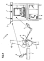
- Device 1 shown comprises a navigation system 2 of a known type, with which the position of marking elements 3, so the position and orientation, can be determined.
- This marking elements 3 can be rigidly attached to instruments and other objects, so that so that the position of these instruments is detected in space.
- Such navigation systems 2 operate e.g. with the help of infrared radiation emitted by a plurality of spaced-apart transmitting and receiving devices 4, reflected at different points of the marking element 3 and then received again by the transmitting and receiving devices 4, the resulting position data of the marking element 3 and thus the Object, to which the marking element 3 is attached, are supplied from the navigation system 2 to a data processing device 5, to which a screen 6 is assigned.
- the described device 1 further comprises a saw jig 7, which is shown only very schematically in the drawing and which serves to guide an oscillating saw blade of a bone saw in a plane, as well as a stylus instrument 8, with the tip of selected points can be approached on bone structures , Both the saw jig 7 and the feeler instrument 8 are each connected to a marking element 3, so that the position of the saw jig and touch instrument by the navigation system 2 is continuously detectable.
- the described device 1 is used to prepare a knee joint 9 for implantation of a unicondylar knee endoprosthesis.
- one of the two articular surfaces 10 remains unchanged, while the other articular surface is removed and replaced on both the tibia 11 and the femur 12 by a unicondylar implant 13.
- a longitudinal axis is first determined in a manner known per se both for the tibia 11 and for the femur 12. This can be achieved, for example, by determining the center of the knee joint and the center of the hip joint or the ankle joint for both bones; Longitudinal axes used.
- both femur and tibia are provided with further marking elements, which are not shown in the drawing. These marking elements then also serve to determine the position of the femur and tibia via the navigation system.
- the saw jig 7 is arranged next to the bone to be processed and oriented such that the sawing plane defined by it defines a contact surface 14 for the implant 13.
- This contact surface 14 will usually lie in the same plane in which the saw jig 7 performs the saw blade of a saw, the plane defining the contact surface 14 is then next to the saw jig 7.
- the location data for a specific position of the saw jig and thus for a particular assumed Contact surface 14 are also supplied to the data processing device 5 and stored in this.
- the geometric data of the implant 13 used is stored in this data processing device 5, for example the height of the implant.
- the implant is arranged on each other bone, and therefore, it is assumed that with regard to the arrangement of the implant on the other bone either from a specific position, or a position of the two bones in a similar way Accepted contact surface and so varied by means of a saw jig 7 until the desired angular orientation of the longitudinal axes 15 and 16 is achieved.
- the data processing device 5 transmits a schematic image of the knee joint to the screen 6 and represents on this the angle that is set between the longitudinal axis 15 and the longitudinal axis 16, if necessary, two views rotated by 90 ° views can be displayed on the screen, so that the Angle is visible in different directions.
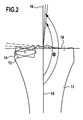
- the representation on the screen can be approximately the representation of the FIG. 2 correspond, in the schematic side by side the unchanged joint surface and the position and orientation of the implant 13 according to the assumed position of the contact surface 14 are visible.
- the longitudinal axes 15 and 16 and their included angle ⁇ are shown.
Landscapes
- Health & Medical Sciences (AREA)
- Surgery (AREA)
- Life Sciences & Earth Sciences (AREA)
- Engineering & Computer Science (AREA)
- General Health & Medical Sciences (AREA)
- Public Health (AREA)
- Veterinary Medicine (AREA)
- Biomedical Technology (AREA)
- Heart & Thoracic Surgery (AREA)
- Medical Informatics (AREA)
- Molecular Biology (AREA)
- Animal Behavior & Ethology (AREA)
- Nuclear Medicine, Radiotherapy & Molecular Imaging (AREA)
- Oral & Maxillofacial Surgery (AREA)
- Pathology (AREA)
- Orthopedic Medicine & Surgery (AREA)
- Physical Education & Sports Medicine (AREA)
- Transplantation (AREA)
- Dentistry (AREA)
- Robotics (AREA)
- Prostheses (AREA)
- Surgical Instruments (AREA)
- Magnetic Resonance Imaging Apparatus (AREA)
- Dental Tools And Instruments Or Auxiliary Dental Instruments (AREA)
Description
- Die Erfindung betrifft eine Vorrichtung zur Bestimmung des Winkels zwischen Femur und Tibia bei der Implantation einer unikondylären Knieprothese mit einem Navigationssystem und einer Datenverarbeitungseinrichtung.
- In der
WO 02/36031 A1 - Auch in der
DE 202 17 014 U1 wird eine Totalendoprothese des Knies beschrieben, also eine Prothese, die alle Gelenkflächen ersetzt. Mit einer Datenverarbeitungseinrichtung können unterschiedliche Winkellagen des Implantates relativ zu Tibia und/oder Femur bestimmt werden und die aus dieser Verschwenkung resultierenden Winkel zwischen Tibia und Femur. Diese unterschiedlichen Winkellagen ergeben sich allein durch die Winkelstellung des Implantates. Im Rahmen dieser Druckschrift werden nur Totalendoprothesen erörtert, das Problem der unikondylären Implantate wird nicht angesprochen. - Neben dem Ersatz eines natürlichen Kniegelenks durch eine vollständige Knieendoprothese ist es in einigen Fällen wünschenswert, das natürliche Kniegelenk nur einseitig zu ersetzen, also nur eine der beiden Kondylen des Kniegelenkes mittels einer Endoprothese zu ersetzen, die andere Gelenkfläche jedoch unverändert zu lassen. Beim Implantieren derartiger unikondylärer Endoprothesen wird sowohl auf den Femur als auch auf die Tibia jeweils ein unikondyläres Implantat aufgesetzt, und diese beiden Implantate ersetzen gegebenenfalls unter Zwischenlage eines Gleitkörpers die natürlichen Gelenkflächen von Femur und Tibia auf einer Seite. Zur Implantation dieser unikondylären Implantate müssen sowohl Tibia als auch Femur bearbeitet werden, die natürlichen Gelenkflächen müssen entfernt werden und es müssen Anlageflächen für diese unikondylären Implantate in den Knochen eingearbeitet werden. Die Lage dieser Anlageflächen muss entsprechend den Abmessungen der verwendeten unikondylären Implantate gewählt werden.
- Es hat sich nun herausgestellt, dass die Lage dieser Anlageflächen und damit die Lage der unikondylären Implantate den Winkel zwischen der Längsachse des Femurs und der Längsachse der Tibia sehr empfindlich beeinflusst. Dies gilt sowohl hinsichtlich einer Translation des Implantates parallel zur Längsrichtung des Femurs bzw. der Tibia als auch hinsichtlich einer Verschwenkung des Implantates gegenüber einer Ebene, die senkrecht auf der Längsachse von Tibia bzw. Femur steht.
- Es ist Aufgabe der Erfindung, eine Vorrichtung der eingangs beschriebenen Art so auszubilden, dass mit ihr der Winkel zwischen Femur und Tibia in Abhängigkeit von der Implantationslage der unikondylären Implantate bestimmt werden kann.
- Diese Aufgabe wird bei einer Vorrichtung der eingangs beschriebenen Art erfindungsgemäß durch eine Ausgestaltung gemäß Anspruch 1 gelöst.
- Die Vorrichtung berechnet also aus den Anlageflächen für das unikondyläre Implantat und damit aufgrund der Lagedaten, also der Position im Raum und der Orientierung im Raum, und aufgrund der Abmessungen des gewünschten Implantates zusammen mit den Lagedaten der unveränderten Gelenkfläche die Gesamtgeometrie des Knies. Aus dieser Gesamtgeometrie ergibt sich dann auch der Winkel zwischen der Längsachse der Tibia und der Längsachse des Femurs. Durch Veränderung der Lagedaten der Anlagefläche lässt sich dieser Winkel beeinflussen, so dass der Operateur die Möglichkeit hat, Winkelkorrekturen vorzunehmen.
- All diese Vorgänge werden durchgeführt, bevor die Anlageflächen in den Knochen eingearbeitet werden, so dass der Operateur die Lage der Anlagefläche vor der Bearbeitung des Knochens beliebig verändern kann, um die optimale Anpassung zu erreichen. Dies gilt auch hinsichtlich der Auswahl von Implantaten mit geeigneten geometrischen Daten, durch Auswahl von Implantaten mit verschiedenen geometrischen Daten und entsprechend angepasster Lage der Anlagefläche kann ebenfalls der Winkel zwischen Femur und Tibia beeinflusst werden.
- Günstig ist es, wenn man die Lage der unveränderten Gelenkfläche durch Lagebestimmung mindestens eines ausgewählten Punktes der unveränderten Gelenkfläche bestimmt. Es ist möglich, die unveränderte Gelenkfläche durch nur einen Punkt zu bestimmen, beispielsweise den tiefsten Punkt der Tibiagelenkfläche, es ist aber auch möglich, beispielsweise die Lage mehrerer markanter Punkte dieser Gelenkfläche zu erfassen, um die Lage der unveränderten Gelenkfläche zu bestimmen.
- Insbesondere kann man den oder die ausgewählten Punkte der unveränderten Gelenkfläche durch Abtasten bestimmen. Es ist dazu vorteilhaft, wenn die Vorrichtung ein navigiertes Tastinstrument zur Bestimmung der Lage der unveränderten Gelenkfläche aufweist.
- Vorzugsweise definiert man die Lage der Anlagefläche vor der Zubereitung der Anlagefläche mittels eines neben Tibia und/oder Femur angeordneten Instrumentes. Vorzugsweise bestimmt man die Lage des Instrumentes mittels eines Navigationssystems, so dass man indirekt durch das Instrument auch die Lage der Anlagefläche durch das Navigationssystem bestimmt.
- Es ist günstig, wenn man als Instrument eine Sägelehre verwendet, die dann gleich zur Führung einer Säge verwendet wird, mit der die Anlagefläche in den Knochen eingearbeitet wird.
- Den Winkel zwischen Femur und Tibia kann man vorzugsweise auf einem Bildschirm anzeigen, so dass der Operateur sofort sieht, welche Einflüsse eine Lageänderung der Anlagefläche und damit des unikondylären Implantates auf den Winkel zwischen Femur und Tibia hat. Der Operateur kann beispielsweise die Sägelehre neben dem zu bearbeitenden Knochen bewegen, bis der Winkel zwischen Femur und Tibia die gewünschte Größe einnimmt, und dann kann diese Sägelehre in der erreichten Position relativ zu dem Knochen fixiert werden, so dass bei Durchführung des Sägeschnittes dann die dem gewünschten Winkel zwischen Femur und Tibia entsprechende Lage der Anlagefläche sichergestellt ist.
- Die nachfolgende Beschreibung bevorzugter Ausführungsformen der Erfindung dient im Zusammenhang mit der Zeichnung der näheren Erläuterung. Es zeigen:
- Figur 1:
- eine schematische Ansicht einer Vorrichtung zur Bestimmung des Winkels zwischen Femur und Tibia mit einem Navigationssystem, einer Datenverarbeitungseinrichtung und einem navigierten Instrument zur Definition der Anlagefläche eines unikondylären Implantates und
- Figur 2:
- eine schematische Ansicht des proximalen Tibiaendes mit einer unveränderten Gelenkfläche und einer durch ein unikondyläres Implantat ersetzten Gelenkfläche.
- Die in
Figur 1 dargestellte Vorrichtung 1 umfasst ein Navigationssystem 2 an sich bekannter Art, mit dem die Lage von Markierelementen 3, also die Position und die Orientierung, festgestellt werden kann. Diese Markierelemente 3 können an Instrumenten und anderen Gegenständen starr befestigt sein, so dass damit auch die Lage dieser Instrumente im Raum feststellbar ist. - Derartige Navigationssysteme 2 arbeiten z.B. mit Hilfe von Infrarotstrahlung, die von mehreren, im Abstand zueinander angeordneten Sende- und Empfangseinrichtungen 4 ausgesandt, an unterschiedlichen Stellen des Markierelementes 3 reflektiert und dann von den Sende- und Empfangseinrichtungen 4 wieder empfangen wird, die daraus gewonnenen Lagedaten des Markierelementes 3 und damit des Gegenstandes, an dem das Markierelement 3 befestigt ist, werden von dem Navigationssystem 2 einer Datenverarbeitungseinrichtung 5 zugeführt, der ein Bildschirm 6 zugeordnet ist.
- Die beschriebene Vorrichtung 1 umfasst weiterhin eine Sägelehre 7, die in der Zeichnung nur sehr schematisch dargestellt ist und die dazu dient, ein oszillierendes Sägeblatt einer Knochensäge in einer Ebene zu führen, sowie ein Tastinstrument 8, mit dessen Spitze ausgewählte Punkte an Knochenstrukturen angefahren werden können. Sowohl die Sägelehre 7 als auch das Tastinstrument 8 sind jeweils mit einem Markierelement 3 verbunden, so dass die Lage von Sägelehre und Tastinstrument durch das Navigationssystem 2 kontinuierlich erfassbar ist.
- Die beschriebene Vorrichtung 1 dient der Vorbereitung eines Kniegelenks 9 zur Implantation einer unikondylären Knieendoprothese. Bei dieser Operation bleibt eine der beiden Gelenkflächen 10 unverändert, während die andere Gelenkfläche entfernt und sowohl an der Tibia 11 als auch am Femur 12 durch ein unikondyläres Implantat 13 ersetzt wird.
- Zur Vorbereitung der Operation wird zunächst in an sich bekannter Weise sowohl für die Tibia 11 als auch für den Femur 12 eine Längsachse bestimmt. Dies lässt sich beispielsweise dadurch erreichen, dass für beiden Knochen der Mittelpunkt des Kniegelenks und der Mittelpunkt des Hüftgelenks bzw. des Knöchelgelenks bestimmt wird, diese Punkte werden zur Festlegung der Längsachsen verwendet. Bei dieser Bestimmung werden sowohl Femur als auch Tibia mit weiteren Markierelementen versehen, die in der Zeichnung nicht dargestellt sind. Diese Markierelemente dienen dann auch dazu, die Lage von Femur und Tibia über das Navigationssystem zu bestimmen.
- Mit Hilfe des Tastinstruments 8 werden geometrische Daten der unveränderten Gelenkfläche 10 aufgenommen, dazu wird mit dem Tastinstrument 8 entweder nur ein ausgewählter Punkt angefahren, gegebenenfalls auch mehrere ausgewählte Punkte, deren Lagedaten in der Datenverarbeitungseinrichtung 5 gespeichert werden.
- Die Sägelehre 7 wird neben dem zu bearbeitenden Knochen angeordnet und so orientiert, dass die von ihr definierte Sägeebene eine Anlagefläche 14 für das Implantat 13 definiert. Diese Anlagefläche 14 wird in der Regel in derselben Ebene liegen, in der die Sägelehre 7 das Sägeblatt einer Säge führt, die die Anlagefläche 14 definierende Ebene liegt dann neben der Sägelehre 7. Die Lagedaten für eine bestimmte Position der Sägelehre und damit für eine bestimmte angenommene Anlagefläche 14 werden ebenfalls der Datenverarbeitungseinrichtung 5 zugeführt und in dieser gespeichert.
- Schließlich werden in dieser Datenverarbeitungseinrichtung 5 noch die geometrischen Daten des verwendeten Implantats 13 gespeichert, beispielsweise die Höhe des Implantates.
- Aus diesen in der Datenverarbeitungseinrichtung 5 gespeicherten Daten berechnet diese den Winkel zwischen den Längsachsen von Tibia und Femur, dieser Winkel hängt von den geometrischen Daten des Implantates und von der Lage des Implantates im Knochen ab, sowohl eine axiale Verschiebung in Richtung der Längsachse der Knochen als auch eine Verschwenkung führt zu einer unterschiedlichen Positionierung des Implantates relativ zur unveränderten Gelenkfläche 10 und damit zu einer Veränderung des Winkels Φ zwischen der Längsachse 15 des Femurs 12 und der Längsachse 16 der Tibia 11. In
Figur 2 sind verschiedene derartige Winkel dargestellt, die sich aufgrund der unterschiedlichen Positionierung des Implantates 13 ergeben können. Dabei geht natürlich auch ein, wie das Implantat am jeweils anderen Knochen angeordnet ist, und daher wird hinsichtlich der Anordnung des Implantates am anderen Knochen entweder von einer bestimmten Position ausgegangen, die angenommen wird, oder es wird an beiden Knochen in ähnlicher Weise eine Lage der Anlagefläche angenommen und mittels einer Sägelehre 7 so variiert, bis die gewünschte Winkelorientierung der Längsachsen 15 und 16 erreicht wird. - Die Datenverarbeitungseinrichtung 5 übermittelt ein schematisches Bild des Kniegelenkes an den Bildschirm 6 und stellt auf diesem den Winkel dar, der sich zwischen der Längsachse 15 und der Längsachse 16 einstellt, gegebenenfalls können auf dem Bildschirm zwei um 90° verdrehte Ansichten dargestellt werden, so dass die Abwinkelung in unterschiedlichen Richtungen sichtbar wird. Die Darstellung auf dem Bildschirm kann etwa der Darstellung der
Figur 2 entsprechen, in der schematisch nebeneinander die unveränderte Gelenkfläche sowie die Lage und Orientierung des Implantates 13 entsprechend der angenommenen Lage der Anlagefläche 14 sichtbar werden. Zusätzlich werden die Längsachsen 15 und 16 und der von ihnen eingeschlossene Winkel Φ dargestellt. - Wenn der Operateur die Lage der Sägelehre 7 relativ zum Knochen verändert, bedeutet dies, dass auch die angenommene Lage der Anlagefläche 14 verschoben wird, und dies führt unmittelbar zu einer Veränderung des Winkels Φ zwischen den beiden Längsachsen 15 und 16. Der Operateur kann durch Lageveränderung der Anlagefläche 14 somit die gewünschte Orientierung dieser Längsachsen einstellen und somit die Anlagefläche 14 bestimmen, die für ein bestimmtes Implantat 13 in den Knochen eingearbeitet werden muss.
Claims (3)
- Vorrichtung zur Bestimmung des Winkels zwischen Femur (12) und Tibia (11) bei der Implantation einer unikondylären Knieprothese mit einem Navigationssystem (2), einer Datenverarbeitungseinrichtung (5), einem Instrument (7) zur Definition der Lage einer Anlagefläche (14) für ein unikondyläres Implantat (13) an der Tibia (11) und/oder am Femur (12), dessen Lage relativ zu der Lage der unveränderten Gelenkfläche (10) durch das Navigationssystem (2) bestimmbar ist, mit einem navigierten Tastinstrument (8) zur Bestimmung der Lage der unveränderten Gelenkfläche (10) und mid einem Speicher in der Datenverarbeitungseinrichtung (5), in dem die Lagedaten des oder der von dem Tastinstrument (8) angefahrenen Punkte der unveränderten Gelenkfläche (10) gespeichert werden, wobei die Datenverarbeitungseinrichtung (5) so programmiert ist, dass sie unter Verwendung der Lagedaten der unverändert bleibenden Gelenkfläche und der angenommenen Lage der Anlagefläche sowie der geometrischen Daten des unikondylären Implantates (13) den Winkel (Φ) zwischen Femur (12) und Tibia (11) berechnet.
- Vorrichtung nach Anspruch 1, dadurch gekennzeichnet, dass das Instrument (7) eine Sägelehre ist.
- Vorrichtung nach einem der Ansprüche 1 oder 2, dadurch gekennzeichnet, dass sie einen Bildschirm (6) umfasst, auf dem die von der Datenverarbeitungseinrichtung (5) berechneten Winkel (Φ) zwischen Femur (12) und Tibia (11) angezeigt werden.
Applications Claiming Priority (1)
| Application Number | Priority Date | Filing Date | Title |
|---|---|---|---|
| PCT/EP2003/010215 WO2005032382A1 (de) | 2003-09-13 | 2003-09-13 | Verfahren und vorrichtung zur bestimmung des winkels zwischen femur und tibia |
Publications (2)
| Publication Number | Publication Date |
|---|---|
| EP1663019A1 EP1663019A1 (de) | 2006-06-07 |
| EP1663019B1 true EP1663019B1 (de) | 2008-02-13 |
Family
ID=34400428
Family Applications (1)
| Application Number | Title | Priority Date | Filing Date |
|---|---|---|---|
| EP03757835A Expired - Lifetime EP1663019B1 (de) | 2003-09-13 | 2003-09-13 | Vorrichtung zur bestimmung des winkels zwischen femur und tibia |
Country Status (7)
| Country | Link |
|---|---|
| US (1) | US20060195048A1 (de) |
| EP (1) | EP1663019B1 (de) |
| AT (1) | ATE385744T1 (de) |
| AU (1) | AU2003273871A1 (de) |
| DE (1) | DE50309180D1 (de) |
| ES (1) | ES2298564T3 (de) |
| WO (1) | WO2005032382A1 (de) |
Families Citing this family (5)
| Publication number | Priority date | Publication date | Assignee | Title |
|---|---|---|---|---|
| US7983777B2 (en) * | 2005-08-19 | 2011-07-19 | Mark Melton | System for biomedical implant creation and procurement |
| US10537392B2 (en) | 2010-03-03 | 2020-01-21 | Brainlab Ag | Method for enabling medical navigation with minimised invasiveness |
| WO2013185811A1 (en) * | 2012-06-13 | 2013-12-19 | Brainlab Ag | Determining a range of motion of an artificial knee joint |
| EP2901946A1 (de) * | 2014-02-03 | 2015-08-05 | Arthrex Inc | Zeigevorrichtung und Bohrwerkzeug |
| USD1121826S1 (en) | 2023-08-18 | 2026-04-07 | Stryker European Operations Limited | Surgical tracker |
Family Cites Families (21)
| Publication number | Priority date | Publication date | Assignee | Title |
|---|---|---|---|---|
| US5682886A (en) * | 1995-12-26 | 1997-11-04 | Musculographics Inc | Computer-assisted surgical system |
| ES2224406T3 (es) * | 1998-06-29 | 2005-03-01 | Plus Endoprothetik Ag | Dispositivo para insertar una protesis de rodilla. |
| ES2260901T3 (es) * | 1999-03-17 | 2006-11-01 | Synthes Ag Chur | Dispositivo de planificacion y guia in situ de un injerto de ligamentos. |
| US7635390B1 (en) * | 2000-01-14 | 2009-12-22 | Marctec, Llc | Joint replacement component having a modular articulating surface |
| US7104996B2 (en) * | 2000-01-14 | 2006-09-12 | Marctec. Llc | Method of performing surgery |
| CA2416114A1 (en) * | 2000-07-28 | 2003-01-27 | Biomet Merck Gmbh | Device for aligning a guide template |
| EP1190676B1 (de) * | 2000-09-26 | 2003-08-13 | BrainLAB AG | Vorrichtung zum Bestimmen der Position eines Schneidblocks |
| FR2816200A1 (fr) * | 2000-11-06 | 2002-05-10 | Praxim | Determination de la position d'une prothese du genou |
| GB0101990D0 (en) * | 2001-01-25 | 2001-03-14 | Finsbury Dev Ltd | Surgical system |
| US6514259B2 (en) * | 2001-02-02 | 2003-02-04 | Carnegie Mellon University | Probe and associated system and method for facilitating planar osteotomy during arthoplasty |
| US7547307B2 (en) * | 2001-02-27 | 2009-06-16 | Smith & Nephew, Inc. | Computer assisted knee arthroplasty instrumentation, systems, and processes |
| EP1372516B1 (de) * | 2001-02-27 | 2009-05-13 | Smith & Nephew, Inc. | Chirurgisches navigationssystem zur teilweisen kniegelenkrekonstruktion |
| WO2003045256A2 (en) * | 2001-11-28 | 2003-06-05 | Wright Medical Technology, Inc. | Instrumentation for minimally invasive unicompartmental knee replacement |
| EP1501406A4 (de) * | 2002-04-16 | 2006-08-30 | Philip C Noble | Computergestützte schulungsverfahren für chirurgische eingriffe |
| US20060106462A1 (en) * | 2002-04-16 | 2006-05-18 | Tsou Paul M | Implant material for minimally invasive spinal interbody fusion surgery |
| US7048741B2 (en) * | 2002-05-10 | 2006-05-23 | Swanson Todd V | Method and apparatus for minimally invasive knee arthroplasty |
| JP2006504477A (ja) * | 2002-11-05 | 2006-02-09 | アエスクラップ アクチェンゲゼルシャフト ウント コンパニー コマンディトゲゼルシャフト | 膝関節内補綴具の位置決定方法および装置 |
| US7789885B2 (en) * | 2003-01-15 | 2010-09-07 | Biomet Manufacturing Corp. | Instrumentation for knee resection |
| US7831295B2 (en) * | 2003-06-05 | 2010-11-09 | Aesculap Ag & Co. Kg | Localization device cross check |
| DE502004004083D1 (de) * | 2004-05-05 | 2007-07-26 | Brainlab Ag | Marknagel-Tracking |
| WO2006034436A2 (en) * | 2004-09-21 | 2006-03-30 | Stout Medical Group, L.P. | Expandable support device and method of use |
-
2003
- 2003-09-13 AT AT03757835T patent/ATE385744T1/de active
- 2003-09-13 ES ES03757835T patent/ES2298564T3/es not_active Expired - Lifetime
- 2003-09-13 EP EP03757835A patent/EP1663019B1/de not_active Expired - Lifetime
- 2003-09-13 AU AU2003273871A patent/AU2003273871A1/en not_active Abandoned
- 2003-09-13 WO PCT/EP2003/010215 patent/WO2005032382A1/de not_active Ceased
- 2003-09-13 DE DE50309180T patent/DE50309180D1/de not_active Expired - Lifetime
-
2006
- 2006-03-08 US US11/372,247 patent/US20060195048A1/en not_active Abandoned
Also Published As
| Publication number | Publication date |
|---|---|
| US20060195048A1 (en) | 2006-08-31 |
| WO2005032382A1 (de) | 2005-04-14 |
| ATE385744T1 (de) | 2008-03-15 |
| DE50309180D1 (de) | 2008-03-27 |
| EP1663019A1 (de) | 2006-06-07 |
| ES2298564T3 (es) | 2008-05-16 |
| AU2003273871A1 (en) | 2005-04-21 |
Similar Documents
| Publication | Publication Date | Title |
|---|---|---|
| EP0969780B1 (de) | Verfahren und vorrichtung zur präoperativen bestimmung der positionsdaten von endoprothesenteilen | |
| DE102004052228B4 (de) | System und Verfahren zum Ausrichten von Bilddaten bezüglich intraoperativ digitalisierter Charakteristika | |
| DE69837781T2 (de) | Zielgerät für Implantatvorrichtungen | |
| DE19956814B4 (de) | Formerfassung von Behandlungsvorrichtungen | |
| EP1190676B1 (de) | Vorrichtung zum Bestimmen der Position eines Schneidblocks | |
| EP1313400B1 (de) | Anordnung zur ermittlung einer belastungsachse einer extremität | |
| EP1558150B1 (de) | Vorrichtung zur bestimmung der lage einer kniegelenkendoprothese | |
| EP2103270B1 (de) | System für navigations-unterstützte Schulteroperationen zur Positionierung navigierter Behandlungsgeräte bezüglich eines Knochens | |
| DE10200690A1 (de) | Hilfsmittel zur Implantation einer Hüftgelenkendoprothese, sowie Verfahren für Handhabung derselben | |
| EP1886640A1 (de) | Planungsverfahren und System zur Freiform-Implantatsanpassung | |
| DE102008023760A1 (de) | Anordnung zur Bestimmung der Position und Lage eines an einem Objekt befindlichen Merkmals | |
| DE10358926B4 (de) | Resektionsschnittlehre | |
| WO2011076308A1 (de) | Femur-schnittführungsvorrichtung für revisionsoperationen in der knie-endoprothetik | |
| EP3242637B1 (de) | Lehre für die bestimmung einer für einen patienten passenden implantatgrösse des femurimplantats einer knie-endoprothese | |
| DE102020116073A1 (de) | Medizintechnische Vorrichtung, Verfahren zum Registrieren eines Modelldatensatzes, Datenverarbeitungsprogramm und Programmspeichermedium | |
| EP1645229B1 (de) | Bänderkraft-Erfassungssystem | |
| EP1522300B1 (de) | Stützvorrichtung | |
| WO2001091647A1 (de) | Vorrichtung zur positionierung eines chirurgischen instrumentes | |
| EP1764064A2 (de) | Vorrichtung und Verfahren zur Bestimmung und Einstellung der optimalen Relativposition einer Funktionsfläche und dementsprechend gestalteten Implantat-Komponenten eines künstlichen Gelenkes | |
| EP1663019B1 (de) | Vorrichtung zur bestimmung des winkels zwischen femur und tibia | |
| EP3429484B1 (de) | Operationsvorrichtung für eine operation des menschlichen knies | |
| DE102005047895B4 (de) | Verfahren und Einrichtung zur Bestimmung der Lage eines Gegenstandes | |
| DE20016635U1 (de) | System zur navigationsgestützten Ausrichtung von Elementen | |
| EP3095398B1 (de) | Patientenspezifisches instrument zur referenzierung von körperteilen | |
| EP1663080A1 (de) | Verfahren und vorrichtung zur bestimmung der beweglichkeit einer h ftgelenkprothese |
Legal Events
| Date | Code | Title | Description |
|---|---|---|---|
| PUAI | Public reference made under article 153(3) epc to a published international application that has entered the european phase |
Free format text: ORIGINAL CODE: 0009012 |
|
| 17P | Request for examination filed |
Effective date: 20060128 |
|
| AK | Designated contracting states |
Kind code of ref document: A1 Designated state(s): AT BE BG CH CY CZ DE DK EE ES FI FR GB GR HU IE IT LI LU MC NL PT RO SE SI SK TR |
|
| 17Q | First examination report despatched |
Effective date: 20060804 |
|
| DAX | Request for extension of the european patent (deleted) | ||
| RTI1 | Title (correction) |
Free format text: DEVICE FOR DETERMINING THE ANGLE BETWEEN THE FEMUR AND THE TIBIA |
|
| GRAP | Despatch of communication of intention to grant a patent |
Free format text: ORIGINAL CODE: EPIDOSNIGR1 |
|
| GRAS | Grant fee paid |
Free format text: ORIGINAL CODE: EPIDOSNIGR3 |
|
| RAP1 | Party data changed (applicant data changed or rights of an application transferred) |
Owner name: AESCULAP AG & CO. KG |
|
| GRAA | (expected) grant |
Free format text: ORIGINAL CODE: 0009210 |
|
| AK | Designated contracting states |
Kind code of ref document: B1 Designated state(s): AT BE BG CH CY CZ DE DK EE ES FI FR GB GR HU IE IT LI LU MC NL PT RO SE SI SK TR |
|
| REG | Reference to a national code |
Ref country code: GB Ref legal event code: FG4D Free format text: NOT ENGLISH |
|
| REG | Reference to a national code |
Ref country code: CH Ref legal event code: EP |
|
| REG | Reference to a national code |
Ref country code: IE Ref legal event code: FG4D Free format text: LANGUAGE OF EP DOCUMENT: GERMAN |
|
| REF | Corresponds to: |
Ref document number: 50309180 Country of ref document: DE Date of ref document: 20080327 Kind code of ref document: P |
|
| REG | Reference to a national code |
Ref country code: ES Ref legal event code: FG2A Ref document number: 2298564 Country of ref document: ES Kind code of ref document: T3 |
|
| GBT | Gb: translation of ep patent filed (gb section 77(6)(a)/1977) |
Effective date: 20080501 |
|
| PG25 | Lapsed in a contracting state [announced via postgrant information from national office to epo] |
Ref country code: FI Free format text: LAPSE BECAUSE OF FAILURE TO SUBMIT A TRANSLATION OF THE DESCRIPTION OR TO PAY THE FEE WITHIN THE PRESCRIBED TIME-LIMIT Effective date: 20080213 |
|
| NLV1 | Nl: lapsed or annulled due to failure to fulfill the requirements of art. 29p and 29m of the patents act | ||
| RAP2 | Party data changed (patent owner data changed or rights of a patent transferred) |
Owner name: AESCULAP AG |
|
| PG25 | Lapsed in a contracting state [announced via postgrant information from national office to epo] |
Ref country code: SI Free format text: LAPSE BECAUSE OF FAILURE TO SUBMIT A TRANSLATION OF THE DESCRIPTION OR TO PAY THE FEE WITHIN THE PRESCRIBED TIME-LIMIT Effective date: 20080213 |
|
| REG | Reference to a national code |
Ref country code: IE Ref legal event code: FD4D |
|
| ET | Fr: translation filed | ||
| PG25 | Lapsed in a contracting state [announced via postgrant information from national office to epo] |
Ref country code: SE Free format text: LAPSE BECAUSE OF FAILURE TO SUBMIT A TRANSLATION OF THE DESCRIPTION OR TO PAY THE FEE WITHIN THE PRESCRIBED TIME-LIMIT Effective date: 20080513 Ref country code: CZ Free format text: LAPSE BECAUSE OF FAILURE TO SUBMIT A TRANSLATION OF THE DESCRIPTION OR TO PAY THE FEE WITHIN THE PRESCRIBED TIME-LIMIT Effective date: 20080213 Ref country code: IE Free format text: LAPSE BECAUSE OF FAILURE TO SUBMIT A TRANSLATION OF THE DESCRIPTION OR TO PAY THE FEE WITHIN THE PRESCRIBED TIME-LIMIT Effective date: 20080213 Ref country code: NL Free format text: LAPSE BECAUSE OF FAILURE TO SUBMIT A TRANSLATION OF THE DESCRIPTION OR TO PAY THE FEE WITHIN THE PRESCRIBED TIME-LIMIT Effective date: 20080213 Ref country code: DK Free format text: LAPSE BECAUSE OF FAILURE TO SUBMIT A TRANSLATION OF THE DESCRIPTION OR TO PAY THE FEE WITHIN THE PRESCRIBED TIME-LIMIT Effective date: 20080213 Ref country code: SK Free format text: LAPSE BECAUSE OF FAILURE TO SUBMIT A TRANSLATION OF THE DESCRIPTION OR TO PAY THE FEE WITHIN THE PRESCRIBED TIME-LIMIT Effective date: 20080213 Ref country code: PT Free format text: LAPSE BECAUSE OF FAILURE TO SUBMIT A TRANSLATION OF THE DESCRIPTION OR TO PAY THE FEE WITHIN THE PRESCRIBED TIME-LIMIT Effective date: 20080714 |
|
| PG25 | Lapsed in a contracting state [announced via postgrant information from national office to epo] |
Ref country code: RO Free format text: LAPSE BECAUSE OF FAILURE TO SUBMIT A TRANSLATION OF THE DESCRIPTION OR TO PAY THE FEE WITHIN THE PRESCRIBED TIME-LIMIT Effective date: 20080213 |
|
| PLBE | No opposition filed within time limit |
Free format text: ORIGINAL CODE: 0009261 |
|
| STAA | Information on the status of an ep patent application or granted ep patent |
Free format text: STATUS: NO OPPOSITION FILED WITHIN TIME LIMIT |
|
| 26N | No opposition filed |
Effective date: 20081114 |
|
| BERE | Be: lapsed |
Owner name: AESCULAP A.G. & CO. KG Effective date: 20080930 |
|
| PG25 | Lapsed in a contracting state [announced via postgrant information from national office to epo] |
Ref country code: EE Free format text: LAPSE BECAUSE OF FAILURE TO SUBMIT A TRANSLATION OF THE DESCRIPTION OR TO PAY THE FEE WITHIN THE PRESCRIBED TIME-LIMIT Effective date: 20080213 Ref country code: BG Free format text: LAPSE BECAUSE OF FAILURE TO SUBMIT A TRANSLATION OF THE DESCRIPTION OR TO PAY THE FEE WITHIN THE PRESCRIBED TIME-LIMIT Effective date: 20080513 Ref country code: MC Free format text: LAPSE BECAUSE OF NON-PAYMENT OF DUE FEES Effective date: 20080930 |
|
| REG | Reference to a national code |
Ref country code: CH Ref legal event code: PL |
|
| PG25 | Lapsed in a contracting state [announced via postgrant information from national office to epo] |
Ref country code: BE Free format text: LAPSE BECAUSE OF NON-PAYMENT OF DUE FEES Effective date: 20080930 Ref country code: CY Free format text: LAPSE BECAUSE OF FAILURE TO SUBMIT A TRANSLATION OF THE DESCRIPTION OR TO PAY THE FEE WITHIN THE PRESCRIBED TIME-LIMIT Effective date: 20080213 |
|
| PG25 | Lapsed in a contracting state [announced via postgrant information from national office to epo] |
Ref country code: CH Free format text: LAPSE BECAUSE OF NON-PAYMENT OF DUE FEES Effective date: 20080930 Ref country code: LI Free format text: LAPSE BECAUSE OF NON-PAYMENT OF DUE FEES Effective date: 20080930 |
|
| PG25 | Lapsed in a contracting state [announced via postgrant information from national office to epo] |
Ref country code: HU Free format text: LAPSE BECAUSE OF FAILURE TO SUBMIT A TRANSLATION OF THE DESCRIPTION OR TO PAY THE FEE WITHIN THE PRESCRIBED TIME-LIMIT Effective date: 20080814 Ref country code: LU Free format text: LAPSE BECAUSE OF NON-PAYMENT OF DUE FEES Effective date: 20080913 |
|
| PG25 | Lapsed in a contracting state [announced via postgrant information from national office to epo] |
Ref country code: TR Free format text: LAPSE BECAUSE OF FAILURE TO SUBMIT A TRANSLATION OF THE DESCRIPTION OR TO PAY THE FEE WITHIN THE PRESCRIBED TIME-LIMIT Effective date: 20080213 |
|
| PG25 | Lapsed in a contracting state [announced via postgrant information from national office to epo] |
Ref country code: GR Free format text: LAPSE BECAUSE OF FAILURE TO SUBMIT A TRANSLATION OF THE DESCRIPTION OR TO PAY THE FEE WITHIN THE PRESCRIBED TIME-LIMIT Effective date: 20080514 |
|
| PGFP | Annual fee paid to national office [announced via postgrant information from national office to epo] |
Ref country code: AT Payment date: 20130919 Year of fee payment: 11 |
|
| PGFP | Annual fee paid to national office [announced via postgrant information from national office to epo] |
Ref country code: IT Payment date: 20130926 Year of fee payment: 11 |
|
| REG | Reference to a national code |
Ref country code: AT Ref legal event code: MM01 Ref document number: 385744 Country of ref document: AT Kind code of ref document: T Effective date: 20140913 |
|
| REG | Reference to a national code |
Ref country code: DE Ref legal event code: R082 Ref document number: 50309180 Country of ref document: DE Representative=s name: HOEGER, STELLRECHT & PARTNER PATENTANWAELTE MB, DE |
|
| PG25 | Lapsed in a contracting state [announced via postgrant information from national office to epo] |
Ref country code: IT Free format text: LAPSE BECAUSE OF NON-PAYMENT OF DUE FEES Effective date: 20140913 Ref country code: AT Free format text: LAPSE BECAUSE OF NON-PAYMENT OF DUE FEES Effective date: 20140913 |
|
| REG | Reference to a national code |
Ref country code: FR Ref legal event code: PLFP Year of fee payment: 14 |
|
| REG | Reference to a national code |
Ref country code: FR Ref legal event code: PLFP Year of fee payment: 15 |
|
| REG | Reference to a national code |
Ref country code: FR Ref legal event code: PLFP Year of fee payment: 16 |
|
| REG | Reference to a national code |
Ref country code: DE Ref legal event code: R082 Ref document number: 50309180 Country of ref document: DE Representative=s name: HOEGER, STELLRECHT & PARTNER PATENTANWAELTE MB, DE |
|
| PGFP | Annual fee paid to national office [announced via postgrant information from national office to epo] |
Ref country code: FR Payment date: 20210927 Year of fee payment: 19 |
|
| PGFP | Annual fee paid to national office [announced via postgrant information from national office to epo] |
Ref country code: GB Payment date: 20210923 Year of fee payment: 19 Ref country code: DE Payment date: 20210921 Year of fee payment: 19 |
|
| PGFP | Annual fee paid to national office [announced via postgrant information from national office to epo] |
Ref country code: ES Payment date: 20211019 Year of fee payment: 19 |
|
| REG | Reference to a national code |
Ref country code: DE Ref legal event code: R119 Ref document number: 50309180 Country of ref document: DE |
|
| GBPC | Gb: european patent ceased through non-payment of renewal fee |
Effective date: 20220913 |
|
| PG25 | Lapsed in a contracting state [announced via postgrant information from national office to epo] |
Ref country code: FR Free format text: LAPSE BECAUSE OF NON-PAYMENT OF DUE FEES Effective date: 20220930 Ref country code: DE Free format text: LAPSE BECAUSE OF NON-PAYMENT OF DUE FEES Effective date: 20230401 |
|
| REG | Reference to a national code |
Ref country code: ES Ref legal event code: FD2A Effective date: 20231027 |
|
| PG25 | Lapsed in a contracting state [announced via postgrant information from national office to epo] |
Ref country code: GB Free format text: LAPSE BECAUSE OF NON-PAYMENT OF DUE FEES Effective date: 20220913 |
|
| PG25 | Lapsed in a contracting state [announced via postgrant information from national office to epo] |
Ref country code: ES Free format text: LAPSE BECAUSE OF NON-PAYMENT OF DUE FEES Effective date: 20220914 |
|
| PG25 | Lapsed in a contracting state [announced via postgrant information from national office to epo] |
Ref country code: ES Free format text: LAPSE BECAUSE OF NON-PAYMENT OF DUE FEES Effective date: 20220914 |