EP1662913B1 - Method and device for the production and bottling of liquids enriched with oxygen - Google Patents
Method and device for the production and bottling of liquids enriched with oxygen Download PDFInfo
- Publication number
- EP1662913B1 EP1662913B1 EP04765306A EP04765306A EP1662913B1 EP 1662913 B1 EP1662913 B1 EP 1662913B1 EP 04765306 A EP04765306 A EP 04765306A EP 04765306 A EP04765306 A EP 04765306A EP 1662913 B1 EP1662913 B1 EP 1662913B1
- Authority
- EP
- European Patent Office
- Prior art keywords
- liquid
- oxygen
- nitrogen
- gas
- container
- Prior art date
- Legal status (The legal status is an assumption and is not a legal conclusion. Google has not performed a legal analysis and makes no representation as to the accuracy of the status listed.)
- Not-in-force
Links
Images


Classifications
-
- B—PERFORMING OPERATIONS; TRANSPORTING
- B67—OPENING, CLOSING OR CLEANING BOTTLES, JARS OR SIMILAR CONTAINERS; LIQUID HANDLING
- B67C—CLEANING, FILLING WITH LIQUIDS OR SEMILIQUIDS, OR EMPTYING, OF BOTTLES, JARS, CANS, CASKS, BARRELS, OR SIMILAR CONTAINERS, NOT OTHERWISE PROVIDED FOR; FUNNELS
- B67C3/00—Bottling liquids or semiliquids; Filling jars or cans with liquids or semiliquids using bottling or like apparatus; Filling casks or barrels with liquids or semiliquids
- B67C3/02—Bottling liquids or semiliquids; Filling jars or cans with liquids or semiliquids using bottling or like apparatus
- B67C3/06—Bottling liquids or semiliquids; Filling jars or cans with liquids or semiliquids using bottling or like apparatus using counterpressure, i.e. filling while the container is under pressure
- B67C3/08—Bottling liquids or semiliquids; Filling jars or cans with liquids or semiliquids using bottling or like apparatus using counterpressure, i.e. filling while the container is under pressure and subsequently lowering the counterpressure
-
- A—HUMAN NECESSITIES
- A23—FOODS OR FOODSTUFFS; TREATMENT THEREOF, NOT COVERED BY OTHER CLASSES
- A23L—FOODS, FOODSTUFFS, OR NON-ALCOHOLIC BEVERAGES, NOT COVERED BY SUBCLASSES A21D OR A23B-A23J; THEIR PREPARATION OR TREATMENT, e.g. COOKING, MODIFICATION OF NUTRITIVE QUALITIES, PHYSICAL TREATMENT; PRESERVATION OF FOODS OR FOODSTUFFS, IN GENERAL
- A23L2/00—Non-alcoholic beverages; Dry compositions or concentrates therefor; Their preparation
- A23L2/52—Adding ingredients
- A23L2/54—Mixing with gases
-
- B—PERFORMING OPERATIONS; TRANSPORTING
- B01—PHYSICAL OR CHEMICAL PROCESSES OR APPARATUS IN GENERAL
- B01F—MIXING, e.g. DISSOLVING, EMULSIFYING OR DISPERSING
- B01F23/00—Mixing according to the phases to be mixed, e.g. dispersing or emulsifying
- B01F23/20—Mixing gases with liquids
- B01F23/23—Mixing gases with liquids by introducing gases into liquid media, e.g. for producing aerated liquids
- B01F23/236—Mixing gases with liquids by introducing gases into liquid media, e.g. for producing aerated liquids specially adapted for aerating or carbonating beverages
-
- B—PERFORMING OPERATIONS; TRANSPORTING
- B01—PHYSICAL OR CHEMICAL PROCESSES OR APPARATUS IN GENERAL
- B01F—MIXING, e.g. DISSOLVING, EMULSIFYING OR DISPERSING
- B01F23/00—Mixing according to the phases to be mixed, e.g. dispersing or emulsifying
- B01F23/20—Mixing gases with liquids
- B01F23/29—Mixing systems, i.e. flow charts or diagrams
-
- B—PERFORMING OPERATIONS; TRANSPORTING
- B01—PHYSICAL OR CHEMICAL PROCESSES OR APPARATUS IN GENERAL
- B01F—MIXING, e.g. DISSOLVING, EMULSIFYING OR DISPERSING
- B01F25/00—Flow mixers; Mixers for falling materials, e.g. solid particles
- B01F25/30—Injector mixers
- B01F25/31—Injector mixers in conduits or tubes through which the main component flows
- B01F25/314—Injector mixers in conduits or tubes through which the main component flows wherein additional components are introduced at the circumference of the conduit
-
- B—PERFORMING OPERATIONS; TRANSPORTING
- B67—OPENING, CLOSING OR CLEANING BOTTLES, JARS OR SIMILAR CONTAINERS; LIQUID HANDLING
- B67C—CLEANING, FILLING WITH LIQUIDS OR SEMILIQUIDS, OR EMPTYING, OF BOTTLES, JARS, CANS, CASKS, BARRELS, OR SIMILAR CONTAINERS, NOT OTHERWISE PROVIDED FOR; FUNNELS
- B67C3/00—Bottling liquids or semiliquids; Filling jars or cans with liquids or semiliquids using bottling or like apparatus; Filling casks or barrels with liquids or semiliquids
- B67C3/02—Bottling liquids or semiliquids; Filling jars or cans with liquids or semiliquids using bottling or like apparatus
- B67C3/06—Bottling liquids or semiliquids; Filling jars or cans with liquids or semiliquids using bottling or like apparatus using counterpressure, i.e. filling while the container is under pressure
- B67C3/10—Bottling liquids or semiliquids; Filling jars or cans with liquids or semiliquids using bottling or like apparatus using counterpressure, i.e. filling while the container is under pressure preliminary filling with inert gases, e.g. carbon dioxide
-
- B—PERFORMING OPERATIONS; TRANSPORTING
- B67—OPENING, CLOSING OR CLEANING BOTTLES, JARS OR SIMILAR CONTAINERS; LIQUID HANDLING
- B67C—CLEANING, FILLING WITH LIQUIDS OR SEMILIQUIDS, OR EMPTYING, OF BOTTLES, JARS, CANS, CASKS, BARRELS, OR SIMILAR CONTAINERS, NOT OTHERWISE PROVIDED FOR; FUNNELS
- B67C7/00—Concurrent cleaning, filling, and closing of bottles; Processes or devices for at least two of these operations
Definitions
- the invention relates to a method and a device for the production and filling of liquids enriched with oxygen or with an oxygen-gas mixture according to the preamble of claims 1 and 10, respectively.
- the oxygen-enriched liquid is kept from impregnation to filling in containers under a pure oxygen atmosphere or an oxygen-gas mixture. Before introducing the liquid into a container, it is also pre-stressed in a filling machine with oxygen or an oxygen-gas mixture. In the entire process, a significant loss of oxygen must be accepted. Pure oxygen is not only expensive but due to its responsiveness in handling also not uncritical.
- the invention is based on the object, an improved method and an apparatus for production and filling of oxygen-enriched liquids and a beverage container available therewith.
- At least one evacuation step is conceivable before introducing the O 2 -enriched liquid before the biasing to a above atmospheric pressure, in particular saturation pressure of the liquid filling pressure takes place. Further, a multiple combined rinse / pre-evacuation treatment of a container prior to biasing is contemplated.
- a further embodiment of the invention provides, before introducing the liquid, introducing a small amount of a liquid gas into the containers, e.g. liquid nitrogen and / or oxygen.
- a liquid gas e.g. liquid nitrogen and / or oxygen.
- the liquefied gas can be rapidly evaporated by a relatively rapid pressure reduction, which also a gas atmosphere, in particular nitrogen can be brought about.
- Liquid oxygen is less critical to handling than pure oxygen in gaseous phase.
- the introduction of the liquid to be filled into the containers can in turn be preceded by a prestressing phase.
- nitrogen need not be limited solely to the containers to be filled, but may also extend to the storage containers in the filling machine as well as in the liquid impregnation system (impregnation tank, storage tanks, etc.), i. the entire manufacturing process starting from the impregnation of a liquid with oxygen to filling into containers can take place continuously under a nitrogen atmosphere.
- nitrogen is not only less critical in its handling, but also significantly less expensive than oxygen.
- the gas space is filled with nitrogen.
- each with a liquid supply line 12 - an inductive flow sensor 13 passing - are connected to the boiler bottom.
- the supply of the continuously circulating drivable ring vessel of the filling machine with the beverage to be filled and said pressurized gas (pure nitrogen) is carried out in a conventional manner via arranged in the center of the filling rotary distributor 14, which with a gas supply line and the other with a buffer tank 15 of an impregnation for liquid supply are conductively connected.
- the impregnation plant has in known manner for the enrichment of a liquid, eg water, lemonade, tea or the like with oxygen via at least one injector 16, which has a connection for the supply of the liquid and at least one further connection for the supply of oxygen. If necessary, further injectors 17 may be present, for example for dissolving CO 2 . If necessary, several parallel injectors with different flow cross-sections can be provided in order to achieve optimum mixing ratios at different throughputs by selecting the appropriate injector (s).
- the liquid supplied from the injector 16, 17 at the outlet side and having a high proportion of dissolved oxygen is conducted into an impregnating or buffer tank 15, which is only partially filled with liquid and has a gas cushion 15 'which is enclosed in the container and acts on the liquid level controlled by a gas supply line and a gas discharge at MedLiteschwankungen pressure regulated. Also, this compressed gas (nitrogen) has an overpressure lying at least above the saturation pressure of the liquid.
- controllable pumps For supplying the injectors and transfer of the ready mixed beverage in the filling machine not shown controllable pumps are provided.
- Each of the filling elements 11 has an electropneumatically controlled actuated liquid valve 18, which is penetrated concentrically by a gas channel 19.
- This in a downwardly projecting gas tube 20 transitional gas channel is connected via a connecting line 21 with a Outlet of the filling member 11 associated valve island 22, which in the present case per Railorgan five individual electropneumatically controlled actuated gas valves 23 to 27 for the course-dependent supply and discharge of the individual process gases in dependence of the filling process, in connection.
- one of said valves 27 opens via a connecting line in a lying below the liquid valve 18 gas gate.
- All valve islands 22 are attached together with the liquid valves 18 to an annular support 28, which in the present case has three fully horizontally extending, closed to ambient atmosphere ring channels 29, 30, 31, which also with associated rotary distributors in the center of the filling machine for Gaszu- or are connected.
- these may be a clean-gas channel 29, a purge gas channel 30 and a discharge or vacuum channel 31.
- a continuously single-track, for example, from a plastic bottles 40 producing stretch blow molding machine (not shown) tapered bottle row is arranged by a in the inlet region of the filling machine 7
- Partial screw 36 is pulled apart on the graduation of Grephery of the filling machine and passed from a subsequent inlet star 37 in the lifting cylinder 32.
- a bottle 40 is detected below its collar, so that its open mouth is held concentrically aligned with the liquid outlet of the overlying positioned Golforgane 11 ( Fig. 2a ).
- the cooperating with the cam roller 32 of the lifting cylinder 32 stationary lifting curve 34 is designed in the circumferential direction so that the bottle 40 is raised with its mouth initially towards the liquid outlet but not yet reached in a gas-tight Anpresssitz with the filling elements 11.
- the gas tube 20 projecting down the liquid outlet dips into the neck space of the bottle 40 to be filled (FIG. Fig. 2b ).
- a purge valve 23 By opening a purge valve 23, a gas connection is opened from the purge gas channel 30 via the connecting line 21 and the gas tube 20 dipping into the bottle, so that in the present case a purge gas consisting essentially of nitrogen flows at high speed into the still unsealed bottle and the original contained air expels through the open bottle mouth. This happens during the in Fig. 1 marked with Pos. 1 circulating area of the filling machine.
- a biasing valve 24 is opened to a conductive between the gas tube 20 and the clean gas duct 29 To open a connection ( Fig. 2c ).
- a presettable biasing pressure preferably 1 to 10 bar, are introduced, which essentially corresponds to the gas pressure prevailing in the ring vessel of the filling machine (circulation area 2 in FIG Fig. 1 ).
- the present between the two spaces mentioned equal pressure can be ensured for example via a connecting line, not shown.
- the existing within the ring vessel 8 of the filling machine 7 gas cushion 10 may also consist of pure nitrogen.
- the boiler internal pressure above the saturation pressure of a beverage enriched with O 2 depends in individual cases on the degree of enrichment of the beverage to be processed and its temperature and is accordingly adjustable.
- the liquid valve 18 Upon reaching the desired biasing pressure in the bottle, the liquid valve 18 is now opened by raising its movable valve body from the associated valve seat, the biasing valve 24 is closed and a return gas valve 25 is actuated.
- the beverage then flows through the bottle mouth into the interior of the bottle and is guided by a deflecting screen attached to the gas tube 20 in the region of the widening bottle shoulder to the bottle wall in order to run from there as liquid film along the bottle wall in the direction of the bottle bottom ( Fig. 2d ). Meanwhile, the inflowing amount of beverage is continuously detected by the inductive flow rate sensor 13.
- the bottle 40 After relieving the bottle 40 is lowered via the correspondingly shaped stationary lifting curve 34 against the force applied by the lifting cylinder 32, upwardly acting pressing force ( Fig. 2g ) and subsequently transferred to the outlet star 38 of the filling machine 7, at the same time the bottle holding the gripping members 35 of the lifting cylinder 32 are opened.
- the filled but still open bottle can be supplied to a capper 39, which applies, for example, a screw-tight gas-tight.
- annular disc-shaped float body 43 can additionally be used in the ring vessel 8, which contains the beverage volume present in the ring vessel essentially covers its entire surface over its surface. Also in the oxygen-containing beverage receiving tanks 15 of lying before the filler impregnation station for the same purpose the liquid level covering float 44 can be used. Instead of float bodies and elastic membranes, bubbles or rolling membranes are conceivable, whereby even a gap-free and thus complete separation of compressed gas and beverage would be achievable.
- noble gases helium, etc.
Abstract
Description
Die Erfindung betrifft ein Verfahren und eine vorrichtung zur Herstellung und Abfüllung von mit Sauerstoff oder mit einem Sauerstoff-Gasgemisch angereicherten Flüssigkeiten gemäß dem Oberbegriff des Anspruchs 1 bzw. 10.The invention relates to a method and a device for the production and filling of liquids enriched with oxygen or with an oxygen-gas mixture according to the preamble of
Verfahren und Vorrichtungen zur Herstellung von mit Sauerstoff stark angereicherten Flüssigkeiten, insbesondere Getränken sind aus dem europäischen Patent
Bei diesen Verfahren wird die mit Sauerstoff angereicherte Flüssigkeit von der Imprägnierung bis zur Abfüllung in Behälter unter einer reinen Sauerstoffatmosphäre oder einem Sauerstoff-Gasgemisch gehalten. Vor dem Einleiten der Flüssigkeit in einen Behälter wird dieser in einer Füllmaschine ebenfalls mit Sauerstoff oder einem Sauerstoff-Gasgemisch vorgespannt. Bei dem gesamten Verfahren muss ein nicht unerheblicher Sauerstoffverlust in Kauf genommen werden. Reiner Sauerstoff ist nicht nur teuer sondern auf Grund seiner Reaktionsfreudigkeit in der Handhabung auch nicht unkritisch.In these processes, the oxygen-enriched liquid is kept from impregnation to filling in containers under a pure oxygen atmosphere or an oxygen-gas mixture. Before introducing the liquid into a container, it is also pre-stressed in a filling machine with oxygen or an oxygen-gas mixture. In the entire process, a significant loss of oxygen must be accepted. Pure oxygen is not only expensive but due to its responsiveness in handling also not uncritical.
Demgegenüber liegt der Erfindung die Aufgabe zu Grunde, ein verbessertes Verfahren und eine Vorrichtung zur Herstellung und Abfüllung von mit Sauerstoff angereicherten Flüssigkeiten sowie einen damit erhältlichen Getränkebehälter anzugeben.In contrast, the invention is based on the object, an improved method and an apparatus for production and filling of oxygen-enriched liquids and a beverage container available therewith.
Diese Aufgabe wird das Verfahren betreffend durch die kennzeichnenden Merkmale des Anspruchs 1 und die Vorrichtung betreffend durch die kennzeichnenden Merkmale des Anspruchs 10 gelöst.This object is achieved by the method concerning the characterizing features of
Während es bislang notwendig erschien, mit einem sehr hohen O2-Gehalt (75 mg/l bis 330 mg/l) angereicherte Flüssigkeiten, insbesondere Getränke wie Mineralwässer, Limonaden, Fruchtsäfte oder dgl. vom Zeitpunkt der O2-Anreicherung bis zur Abfüllung in Behälter, wie Flaschen, Dosen oder andere geeignete Gefäße unter einer Sauerstoffatmosphäre oder einem Sauerstoff-Gasgemisch zu halten, um eine O2-Entbindung zu vermeiden, verlässt die Erfindung diesen weg und nutzt die überraschende Erkenntnis, dass auf Grund der im laufenden Herstell- und Abfüllprozess nur kurzen verweilzeit der Flüssigkeit im System auch nur eine kurze Kontaktzeit zwischen der angereicherten Flüssigkeit und dem erfindungsgemäß verwendeten Stickstoff besteht. Es hat sich überraschenderweise gezeigt, dass bei einer Vorspannung der zu befüllenden Behälter mit Stickstoff keine negative Rückwirkung auf die O2-angereicherte Flüssigkeit auftritt, d.h. der gelöste O2-Gehalt wird nicht nennenswert beeinflusst und es findet praktisch keine Stickstoffaufnahme in die Flüssigkeit statt. Diese Effekte dürften auf das nur träge Lösungsverhalten von Stickstoff zurückzuführen sein.While it seemed necessary hitherto, with a very high O 2 content (75 mg / l to 330 mg / l) enriched liquids, especially beverages such as mineral waters, lemonades, fruit juices or the like. From the time of O 2 enrichment to bottling in To keep containers, such as bottles, cans or other suitable vessels under an oxygen atmosphere or an oxygen-gas mixture in order to avoid an O 2 unbound, the invention leaves this way and takes advantage of the surprising finding that due to the ongoing manufacturing and Filling process only a short residence time of the liquid in the system, there is only a short contact time between the enriched liquid and the nitrogen used in the invention. It has surprisingly been found that with a bias of the container to be filled with nitrogen no negative reaction to the O 2 -richereicherte liquid occurs, ie, the dissolved O 2 content is not significantly affected and there is virtually no nitrogen uptake into the liquid instead. These effects are probably due to the slow dissolution behavior of nitrogen.
Gemäß einer vorteilhaften Weiterbildung kann dem Vorspannen der Behälter mit Stickstoff auch eine Spülbehandlung, ebenfalls mit Stickstoff, vorausgehen.According to an advantageous development of the biasing of the container with nitrogen and a rinsing treatment, also preceded by nitrogen.
Bei formstabilen Behältnissen, z.B. Glasflaschen, ist vor dem Einleiten der O2-angereicherten Flüssigkeit alternativ oder zusätzlich wenigstens ein Evakuierungsschritt denkbar, bevor das Vorspannen auf einen über dem Atmosphärendruck, insbesondere Sättigungsdruck der Flüssigkeit liegenden Fülldruck erfolgt. Ferner ist eine mehrfach kombinierte Spül- /vorevakuierungsbehandlung eines Behälters vor dem Vorspannen denkbar.In dimensionally stable containers, eg glass bottles, alternatively or additionally at least one evacuation step is conceivable before introducing the O 2 -enriched liquid before the biasing to a above atmospheric pressure, in particular saturation pressure of the liquid filling pressure takes place. Further, a multiple combined rinse / pre-evacuation treatment of a container prior to biasing is contemplated.
Eine weitere Ausgestaltung der Erfindung sieht vor dem Einleiten der Flüssigkeit ein Einbringen einer geringen Menge eines flüssigen Gases in die Behältnisse vor, z.B. flüssigen Stickstoff und/oder Sauerstoff. Mit einer darauffolgenden kurzzeitigen Evakuierung kann das Flüssiggas durch eine verhältnismäßig schnelle Druckabsenkung zügig verdampft werden, wodurch ebenfalls eine Gasatmosphäre, insbesondere aus Stickstoff herbeiführbar ist. Flüssiger Sauerstoff ist in der Handhabung unkritischer als reiner Sauerstoff in gasförmiger Phase. Natürlich kann dem Einleiten der abzufüllenden Flüssigkeit in die Behältnisse wiederum eine vorspannphase vorausgehen.A further embodiment of the invention provides, before introducing the liquid, introducing a small amount of a liquid gas into the containers, e.g. liquid nitrogen and / or oxygen. With a subsequent short-term evacuation, the liquefied gas can be rapidly evaporated by a relatively rapid pressure reduction, which also a gas atmosphere, in particular nitrogen can be brought about. Liquid oxygen is less critical to handling than pure oxygen in gaseous phase. Of course, the introduction of the liquid to be filled into the containers can in turn be preceded by a prestressing phase.
Die Verwendung von Stickstoff muss nicht allein auf die zu befüllenden Behältnisse beschränkt sein, sondern kann sich auch auf die Speicherbehälter in der Füllmaschine sowie in der Flüssigkeitsimprägnieranlage (Imprägniertank, Speichertanks etc.) erstrecken, d.h. der gesamte Herstellprozess beginnend von der Imprägnierung einer Flüssigkeit mit Sauerstoff bis zur Abfüllung in Behältnisse kann durchgehend unter einer Stickstoffatmosphäre stattfinden.The use of nitrogen need not be limited solely to the containers to be filled, but may also extend to the storage containers in the filling machine as well as in the liquid impregnation system (impregnation tank, storage tanks, etc.), i. the entire manufacturing process starting from the impregnation of a liquid with oxygen to filling into containers can take place continuously under a nitrogen atmosphere.
Vorteilhafter Weise ist Stickstoff in seiner Handhabung nicht nur unkritischer, sondern auch deutlich kostengünstiger als Sauerstoff.Advantageously, nitrogen is not only less critical in its handling, but also significantly less expensive than oxygen.
weitere vorteilhafte Ausgestaltungen sind Gegenstand der verbleibenden Unteransprüche.Further advantageous embodiments are the subject of the remaining dependent claims.
Nachfolgend wird ein bevorzugtes Ausführungsbeispiel anhand der Figuren erläutert. Es zeigt:
- Fig. 1
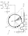
- eine Draufsicht einer Vorrichtung zum Herstellen und Abfüllen von Getränken in Flaschen in einer schematischen Darstellung und
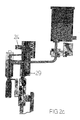
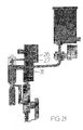
- Fig. 2a bis 2g
- jeweils einen vertikalen Teilschnitt durch die äußere Peripherie einer Füllmaschine nach
Fig. 1 in mehreren zeitlich aufeinanderfolgenden Betriebszuständen.
- Fig. 1
- a plan view of an apparatus for producing and filling drinks in bottles in a schematic representation and
- Fig. 2a to 2g
- in each case a vertical partial section through the outer periphery of a filling machine
Fig. 1 in several successive operating states.
Eine Anlage zum Herstellen und Abfüllen von mit Sauerstoff angereicherten Flüssigkeiten, insbesondere Getränken, verfügt gemäß
Entlang der Peripherie des Ringkessels befinden sich in gleichmäßigen Teilungsabständen über den gesamten Umfang verteilt angeordnete Füllorgane 11, die jeweils mit einer Flüssigkeitszuleitung 12 - einen induktiven Durchflussmesssensor 13 passierend - an der Kesselunterseite angeschlossen sind. Die Versorgung des kontinuierlich umlaufend antreibbaren Ringkessels der Füllmaschine mit dem abzufüllenden Getränk und dem genannten Druckgas (reiner Stickstoff) erfolgt in an sich bekannter Weise über im Zentrum der Füllmaschine angeordnete Drehverteiler 14, die zum einen mit einer Gaszuführungsleitung und zum anderen mit einem Puffertank 15 einer Imprägnieranlage zur Flüssigkeitszuführung leitend in Verbindung stehen.Along the periphery of the ring bowl are arranged at uniform pitch intervals over the entire circumference arranged
Die Imprägnieranlage verfügt in an sich bekannter Weise zur Anreicherung einer Flüssigkeit, z.B. Wasser, Limonade, Tee oder dgl. mit Sauerstoff über wenigstens einen Injektor 16, der einen Anschluss für die Zuführung der Flüssigkeit und wenigstens einen weiteren Anschluss zur Einspeisung von Sauerstoff besitzt. Bedarfsweise können noch weitere Injektoren 17, z.B. zum Lösen von CO2 vorhanden sein. Gebenenfalls können mehrere parallel geschaltete Injektoren mit unterschiedlichen Durchflussquerschnitten vorgesehen werden, um bei unterschiedlichen Durchsatzmengen durch Auswahl des/der passenden Injektors(-en) optimale Mischverhältnisse zu erzielen.The impregnation plant has in known manner for the enrichment of a liquid, eg water, lemonade, tea or the like with oxygen via at least one
Die aus dem verwendeten Injektor 16, 17 auslaufseitig gelieferte, einen hohen Anteil gelösten Sauerstoff aufweisende Flüssigkeit wird in einen Imprägnier- bzw. Puffertank 15 geleitet, der nur teilweise flüssigkeitsgefüllt ist und ein auf den Flüssigkeitsspiegel wirkendes, im Behälter eingeschlossenes Gaspolster 15' aufweist, das durch eine Gaszuleitung und eine Gasableitung bei Füllspiegelschwankungen gesteuert druckregulierbar ist. Auch dieses Druckgas (Stickstoff) weist einen wenigstens über dem Sättigungsdruck der Flüssigkeit liegenden Überdruck auf.The liquid supplied from the
Zur Speisung der Injektoren sowie Überführung des fertig gemischten Getränks in die Füllmaschine sind nicht dargestellte regelbare Pumpen vorgesehen.For supplying the injectors and transfer of the ready mixed beverage in the filling machine not shown controllable pumps are provided.
Jedes der Füllorgane 11 verfügt über ein elektropneumatisch gesteuert betätigbares Flüssigkeitsventil 18, das konzentrisch von einem Gaskanal 19 durchgriffen wird. Dieser in ein nach unten vorstehendes Gasröhrchen 20 übergehende Gaskanal steht über eine Anschlussleitung 21 mit einem Auslass einer dem Füllorgan 11 zugeordneten Ventilinsel 22, die im vorliegenden Fall pro Füllorgan fünf einzelne elektropneumatisch gesteuert betätigbare Gasventile 23 bis 27 zum verlaufsabhängigen Zu- und Abführen der einzelnen Prozessgase in Abhängigkeit des Füllprozesses aufweist, in Verbindung. Eines der genannten Ventile 27 mündet allerdings über eine Verbindungsleitung in einen unterhalb des Flüssigkeitsventils 18 liegenden Gasanschnitt ein.Each of the
Alle Ventilinseln 22 sind gemeinsam mit den Flüssigkeitsventilen 18 an einem ringförmigen Träger 28 befestigt, der im vorliegenden Fall drei vollumfänglich horizontal verlaufende, zur Umgebungsatmosphäre geschlossene Ringkanäle 29, 30, 31 aufweist, die ebenfalls mit zugeordneten Drehverteilern im Zentrum der Füllmaschine zur Gaszu- oder -abfuhr verbunden sind. Dies können im Einzelnen ein Reingaskanal 29, ein Spülgaskanal 30 und ein Entlastungs- bzw. Vakuumkanal 31 sein.All
Im Bereich unterhalb der Füllorgane 11 befinden sich über eine verdrehfeste Hubkurve 34 in Verbindung mit Kurvenrollen 33 gesteuert heb- und senkbare pneumatische Hubzylinder 32, die jeweils einen unterhalb am Halskragen von Kunststoffflaschen 40 angreifendes Greif- oder Halteorgan 35 besitzen. Ein im Hubzylinder eingeschlossenes Gaspolster übt während eines gesamten Umlaufs permanent eine in Richtung nach oben zum Füllorgan 11 gerichtete Anpresskraft aus.In the area below the
Nachfolgend wird ein vollständiger Abfüllzyklus einer Flasche anhand der die einzelnen Füllphasen darstellende Figurenfolge 2a bis 2g erläutert:In the following, a complete filling cycle of a bottle will be explained on the basis of the sequence of figures 2a to 2g representing the individual filling phases:
Eine kontinuierlich einspurig beispielsweise von einer Kunststoffflaschen 40 herstellenden Streckblasmaschine (nicht dargestellt) zulaufende Flaschenreihe wird von einer im Einlaufbereich der Füllmaschine 7 angeordneten Einteilschnecke 36 auf das Teilungsmaß der Füllorgane am Umfang der Füllmaschine auseinandergezogen und von einem nachfolgenden Einlaufstern 37 in die Hubzylinder 32 übergeben. Dabei wird jeweils eine Flasche 40 unterhalb ihres Halskragens erfasst, derart, dass ihre offene Mündung konzentrisch zum Flüssigkeitsauslauf des darüber liegend positionierten Füllorgane 11 ausgerichtet gehalten wird (
Die mit der Kurvenrolle 32 des Hubzylinders 32 zusammenwirkende stationäre Hubkurve 34 ist in Umlaufrichtung so gestaltet, dass die Flasche 40 mit ihrer Mündung zunächst in Richtung zum Flüssigkeitsauslauf angehoben aber noch nicht in einen gasdichten Anpresssitz mit dem Füllorgane 11 gelangt. Während dieses Vorgangs taucht das den Flüssigkeitsauslass nach unten überragende Gasröhrchen 20 in den Halsraum der zu befüllenden Flasche 40 ein (
Durch nachfolgendes Anheben der Flasche 40 mittels des Hubzylinders 32 wird deren Mündung gasdicht gegen den Füllauslauf des Füllorgans 11 unterhalb des Flüssigkeitsventils 18 angepresst, woraufhin nach dem Schließen des Spülventils 23 ein Vorspannventil 24 geöffnet wird, um zwischen dem Gasröhrchen 20 und dem Reingaskanal 29 eine leitende Verbindung zu eröffnen (
Bei Erreichen des gewünschten Vorspanndrucks in der Flasche wird nun das Flüssigkeitsventil 18 durch Anheben seines beweglichen Ventilkörpers vom zugeordneten Ventilsitz geöffnet, das vorspannventil 24 geschlossen und ein Rückgasventil 25 betätigt. Im weiteren Verlauf strömt nun das Getränk durch die Flaschenmündung in den Flascheninnenraum und wird durch ein im Bereich der sich erweiternden Flaschenschulter am Gasröhrchen 20 angebrachtes Abweisschirmchen an die Flaschenwandung geleitet, um von dort als Flüssigkeitsfilm an der Flaschenwandung entlang in Richtung zum Flaschenboden einzulaufen (
Nach dem Entlasten wird die Flasche 40 über die entsprechend gestaltete stationäre Hubkurve 34 entgegen der vom Hubzylinder 32 aufgebrachten, nach oben wirkenden Presskraft abgesenkt (
Es ist denkbar, auf dem Weg vom Füller 7 zur Verschließmaschine 39 durch eine in diesem Transportbereich angeordnete steuerbare Einspritzvorrichtung 42 flüssigen Stickstoff und/oder Sauerstoff in den offenen Kopfraum der Flaschen impulsartig gesteuert einzudüsen, bevor ein Verschluss aufgesetzt wird.It is conceivable, on the way from the filler 7 to the capping
Ebenso ist eine Eindüsung von flüssige Stickstoff und/oder Sauerstoff durch eine Einspritzvorrichtung 41 im Bereich vor dem Einlauf der Füllmaschine 7 denkbar, vor allem, wenn vor dem Einleiten der abzufüllenden Flüssigkeit kurzzeitig ein Vakuum erzeugt wird, indem das im Entlastungskanal vorhandene Vakuum vorübergehend mit der Flasche in Wirkverbindung gebracht wird. Es versteht sich, dass in diesem Falle die Flaschen in Abhängigkeit des gewünschten Unterdrucks eine ausreichende Formstabilität besitzen müssen, wie dies beispielsweise bei Glasflaschen ohne weiteres der Fall ist.Likewise, an injection of liquid nitrogen and / or oxygen by an
Um im Ringkessel 8 der Füllmaschine 7 oder auch im Puffer- bzw. Sammeltank 15 der Getränkeimprägnierstation einen Gasaustausch zwischen der Stickstoffatmosphäre und dem darunter liegenden Getränk zuverlässig zu vermeiden, kann im Ringkessel 8 zusätzlich ein ringscheibenförmiger Schwimmerkörper 43 verwendet werden, der das im Ringkessel vorhandene Getränkevolumen an seiner Oberfläche im Wesentlichen vollflächig abdeckt. Auch in den das sauerstoffhaltige Getränk aufnehmenden Tanks 15 der vor dem Füller liegenden Imprägnierstation können zum gleichen Zweck den Flüssigkeitsspiegel abdeckende Schwimmer 44 zum Einsatz kommen. Anstelle von Schwimmerkörpern sind auch elastische Membranen, Blasen oder Rollmembranen denkbar, wodurch sogar eine spaltfreie und damit vollständige Trennung von Druckgas und Getränk erreichbar wäre.In order to reliably avoid gas exchange between the nitrogen atmosphere and the underlying drink in the
Alternativ zum vorgeschlagenen Stickstoff könnten ggf. Edelgase (Helium etc.) zum Einsatz kommen, die allerdings in der Beschaffung teurer sind.As an alternative to the proposed nitrogen, noble gases (helium, etc.) could possibly be used, but they are more expensive to procure.
Claims (15)
- A method for the preparation and bottling of liquids, in particular beverages, enriched with oxygen or with an oxygen/gas mixture, in containers, in particular bottles or cans, wherein the liquid enriched with oxygen and, optionally, other gases, in particular in dissolved form, is filled into containers which are then sealed in a pressure-tight manner, characterised in that the enriched liquid is kept under a nitrogen atmosphere at least temporarily during the bottling process.
- A method according to the preamble of Claim 1, characterised in that the liquid is kept under a nitrogen atmosphere at least temporarily starting from the time of enrichment with oxygen or an oxygen/gas mixture.
- A method according to Claim 1 or 2, characterised in that the liquid is kept under a nitrogen atmosphere starting from the time of enrichment until the desired filling level in the container is reached.
- A method according to at least one of the preceding Claims 1 to 3, characterised in that the nitrogen atmosphere is at overpressure, preferably in the range between 1 and 10 bar.
- A method according to at least one of the preceding Claims 1 to 4, characterised in that, prior to the introduction of the enriched liquid, a container is pre-pressurised with nitrogen, in particular to a pressure corresponding to the filling pressure of the liquid.
- A method according to at least one of the preceding Claims 1 to 5, characterised in that, prior to the introduction of the liquid, in particular prior to the pre-pressurisation, the container is flushed at least once, preferably with nitrogen.
- A method according to at least one of the preceding Claims 1 to 6, characterised in that the container is evacuated at least once prior to the introduction of the liquid, in particular prior to a pre-pressurisation with nitrogen, preferably before and/or after flushing of the container, preferably with nitrogen.
- A method according to Claim 6 or 7, characterised in that when the liquid is introduced into the container, return gas expelled therefrom is collected and used for a flushing treatment of subsequent containers.
- A method according to at least one of the preceding Claims 1 to 8, characterised in that a gas in liquid phase, preferably liquid nitrogen and/or oxygen, is introduced into the container prior to the introduction of the liquid, in particular prior to an evacuation step.
- A device for the preparation and bottling of liquids (45), in particular beverages, enriched with oxygen or with an oxygen/gas mixture in containers (40), in particular bottles or cans, wherein the liquid enriched with oxygen and, optionally, other gases, in particular in dissolved form, is filled into the containers by the device and they are then sealed in a pressure-tight manner with a closure, in particular for carrying out the method according to at least one of Claims 1 to 9, characterised in that the device (7) has at least one filling member (11) with a liquid valve (18), at least one gas valve (23, 34) and a nitrogen-filled chamber (10,29,30), wherein a flow connection for flushing and/or pre-pressurising the container (40) with nitrogen can be established between a container (46) applied to the filling member (11) and the chamber (10,29,30) via the gas valve (23,24), and in that the device (7) has a reservoir (8) partially filled with liquid (9), and the liquid in the reservoir can be pressurised with nitrogen, preferably in the range from 1 to 10 bar.
- A device according to Claim 10, characterised in that the filling member (11) can be connected to a flushing gas channel (30) via a flushing valve (23) and/or to a pure gas channel (29) via a pre-pressurisation valve (24).
- A device according to Claim 10 or 11, characterised in that the filling member (11) can be connected to a relief and/or vacuum channel (30) via at least one relief valve (26,27).
- A device according to the preamble of Claim 10, characterised in that, after enrichment with oxygen, liquid is directed into a partially filled tank (15) and can be pressurised with nitrogen.
- A device according to Claim 10 or 13, characterised in that the liquid in the reservoir (8) and/or tank (15) can be separated from the pressure-exerting gas at least approximately completely, in particular by movable floats (43,44) or elastic membranes.
- A device according to the preamble of Claim 10, characterised in that an apparatus (41) for introducing liquid gas, in particular nitrogen or oxygen, into the open containers is disposed upstream of the device (7) for filling containers (40).
Applications Claiming Priority (2)
| Application Number | Priority Date | Filing Date | Title |
|---|---|---|---|
| DE10343281A DE10343281A1 (en) | 2003-09-18 | 2003-09-18 | Method and device for producing and filling oxygen-enriched liquids |
| PCT/EP2004/010407 WO2005029982A1 (en) | 2003-09-18 | 2004-09-16 | Method and device for the production and bottling of liquids enriched with oxygen |
Publications (2)
| Publication Number | Publication Date |
|---|---|
| EP1662913A1 EP1662913A1 (en) | 2006-06-07 |
| EP1662913B1 true EP1662913B1 (en) | 2009-08-26 |
Family
ID=34352946
Family Applications (1)
| Application Number | Title | Priority Date | Filing Date |
|---|---|---|---|
| EP04765306A Not-in-force EP1662913B1 (en) | 2003-09-18 | 2004-09-16 | Method and device for the production and bottling of liquids enriched with oxygen |
Country Status (7)
| Country | Link |
|---|---|
| US (1) | US7721773B2 (en) |
| EP (1) | EP1662913B1 (en) |
| CN (1) | CN1852667B (en) |
| AT (1) | ATE440510T1 (en) |
| DE (2) | DE10343281A1 (en) |
| RU (1) | RU2391878C2 (en) |
| WO (1) | WO2005029982A1 (en) |
Families Citing this family (28)
| Publication number | Priority date | Publication date | Assignee | Title |
|---|---|---|---|---|
| DE102006062536A1 (en) | 2006-12-29 | 2008-07-03 | Krones Ag | Container e.g. plastic bottle, filling device, has measuring device provided downstream concerning closing device for determining characteristic variable for geometrical form of container |
| DE102007031961A1 (en) | 2007-07-10 | 2009-01-15 | Krones Ag | Container treatment machine and conveyor line section |
| DE102007048934A1 (en) | 2007-10-12 | 2009-04-16 | Krones Ag | Device for bottling beverages |
| DE102007058047A1 (en) | 2007-11-30 | 2009-06-10 | Khs Ag | Method and device for filling liquids |
| US8142550B2 (en) | 2008-12-16 | 2012-03-27 | Oxy Solutions As | Oxygenation of a fluid |
| DE102010031478A1 (en) * | 2010-07-16 | 2012-01-19 | Krones Aktiengesellschaft | Apparatus and method for providing a reusable liquid product to be treated |
| US20120152791A1 (en) * | 2010-12-20 | 2012-06-21 | Air Liquide Industrial U.S. Lp | Method for effective de-oxygenation of product containers for use as containers for oxygen sensitive products |
| WO2012137317A1 (en) * | 2011-04-06 | 2012-10-11 | 三菱重工食品包装機械株式会社 | Rotary-type filling machine and method for calculating filling quantity for rotary-type filling machine |
| CN103090179B (en) * | 2013-01-28 | 2018-01-30 | 扬州美达灌装机械有限公司 | Bottle placer under full-automatic high-purity oxygen lid |
| DE102013102547A1 (en) * | 2013-03-13 | 2014-09-18 | Khs Gmbh | Method and filling machine for filling cans or the like. Containers with a liquid product |
| DE102013108638A1 (en) * | 2013-08-09 | 2015-03-05 | Khs Gmbh | Method and system for rinsing containers |
| DE102013109430A1 (en) * | 2013-08-30 | 2015-03-05 | Khs Gmbh | Method and filling system for filling containers |
| EP2871150B1 (en) * | 2013-11-08 | 2017-02-01 | Sidel S.p.a. Con Socio Unico | Filling unit and method for filling an article with a pourable product |
| DE102014104873A1 (en) * | 2014-04-04 | 2015-10-08 | Krones Ag | Method and device for filling a container with a filling product |
| DE102014104872A1 (en) * | 2014-04-04 | 2015-10-08 | Krones Ag | Method and device for filling a container to be filled with a filling product |
| US20160289617A1 (en) * | 2014-11-05 | 2016-10-06 | Prosper Brands LLC | Gas-infused fluids and methods of making and using same |
| DE102014117279A1 (en) * | 2014-11-25 | 2016-05-25 | Krones Ag | Device for filling a container with a filling product |
| EP3225683A1 (en) * | 2016-03-30 | 2017-10-04 | Anheuser-Busch InBev S.A. | Kit for the in situ production of a fermented target beverage by addition of a liquid diluent |
| CN105836691B (en) * | 2016-05-17 | 2017-12-12 | 南京海益思生物科技有限公司 | A kind of filling liquid and inert gas filling protection integrated device and its packaging process |
| EP3522995A1 (en) * | 2016-10-05 | 2019-08-14 | Tyco Building Services Products Limited | Methods and system for filling a suppressant container |
| DE102017114392A1 (en) * | 2017-06-28 | 2019-01-03 | Krones Ag | Device for treating a container in a filling product filling plant |
| DE102017123253A1 (en) * | 2017-10-06 | 2019-04-11 | Krones Ag | Method and device for filling a container to be filled with a filling product |
| US10925299B2 (en) * | 2018-03-06 | 2021-02-23 | Kerflummox Holdings, LLC | C. bot prevention in infused coffee |
| FR3093328B1 (en) * | 2019-02-28 | 2021-02-19 | Bonduelle Sa Ets | Product packaging process |
| CN109999705A (en) * | 2019-04-30 | 2019-07-12 | 舟山丰冠轻工机械有限公司 | A kind of filling tin seamer material cylinder and feed liquid stirring means with agitating function |
| DE102019111929A1 (en) * | 2019-05-08 | 2020-11-12 | Khs Gmbh | Filling machine and method for filling containers with a liquid filling material |
| DE102019130052A1 (en) * | 2019-11-07 | 2021-05-12 | Khs Gmbh | Method for filling and closing containers |
| CN113697749A (en) * | 2021-08-31 | 2021-11-26 | 合肥中辰轻工机械有限公司 | System and method for rapidly and steplessly adjusting flow rate of filling valves in batches |
Family Cites Families (13)
| Publication number | Priority date | Publication date | Assignee | Title |
|---|---|---|---|---|
| US4120425A (en) * | 1972-09-01 | 1978-10-17 | The Champagne Machine Inc. | Apparatus for dispensing sparkling wines |
| GB2235759A (en) * | 1989-09-04 | 1991-03-13 | Guinness Son & Co Ltd A | Liquid dispensing system and packaging apparatus |
| FR2736041B1 (en) * | 1995-06-30 | 1997-08-29 | Deep | METHOD FOR FILLING A BOTTLE, PARTICULARLY IN PLASTIC MATERIAL, WITH A LIQUID AND ASSOCIATED DEVICE |
| EP0847959B2 (en) * | 1996-11-19 | 2007-10-17 | Kramer & Co. OEG | Method for preparing and filling of oxygen-enriched or oxygen containing gas enriched liquids |
| DE29718062U1 (en) * | 1997-04-29 | 1998-05-20 | Till Gea Gmbh & Co | Device for filling containers |
| DE29712148U1 (en) * | 1997-04-29 | 1997-09-11 | Till Gea Gmbh & Co | Device for filling containers |
| ATE254086T1 (en) * | 1997-09-04 | 2003-11-15 | Kramer & Co Oeg | METHOD FOR THE PRODUCTION AND FILLING OF LIQUIDS AND BEVERAGES ENRICHED WITH OXYGEN OR AN OXYGEN-GAS MIXTURE |
| JP4352192B2 (en) * | 1999-11-16 | 2009-10-28 | 澁谷工業株式会社 | Gas filling machine |
| DE10008426B4 (en) * | 2000-02-23 | 2011-07-28 | KHS GmbH, 44143 | System and method for filling containers with a liquid product |
| DE10104207A1 (en) | 2001-01-31 | 2002-10-24 | Adelholzener Alpenquellen Gmbh | Compressed oxygen and carbon dioxide admixed to and impregnating water under pressure |
| US6457495B1 (en) * | 2001-03-31 | 2002-10-01 | Dave Meheen | Filling apparatus and methods |
| DE10121841C1 (en) * | 2001-05-05 | 2003-05-22 | Hechtl Oliver J | Process for the preparation of drinking water enriched with all air gas components |
| US20030232114A1 (en) * | 2002-06-13 | 2003-12-18 | Nikola Dekleva | Method for liquid enrichment with oxygen and applications of enriched liquids |
-
2003
- 2003-09-18 DE DE10343281A patent/DE10343281A1/en not_active Withdrawn
-
2004
- 2004-09-16 US US10/572,356 patent/US7721773B2/en not_active Expired - Fee Related
- 2004-09-16 RU RU2006112835/13A patent/RU2391878C2/en not_active IP Right Cessation
- 2004-09-16 CN CN2004800269224A patent/CN1852667B/en not_active Expired - Fee Related
- 2004-09-16 DE DE502004009976T patent/DE502004009976D1/en active Active
- 2004-09-16 AT AT04765306T patent/ATE440510T1/en not_active IP Right Cessation
- 2004-09-16 EP EP04765306A patent/EP1662913B1/en not_active Not-in-force
- 2004-09-16 WO PCT/EP2004/010407 patent/WO2005029982A1/en active Search and Examination
Also Published As
| Publication number | Publication date |
|---|---|
| RU2391878C2 (en) | 2010-06-20 |
| CN1852667A (en) | 2006-10-25 |
| CN1852667B (en) | 2010-05-05 |
| DE10343281A1 (en) | 2005-04-21 |
| DE502004009976D1 (en) | 2009-10-08 |
| WO2005029982A1 (en) | 2005-04-07 |
| EP1662913A1 (en) | 2006-06-07 |
| ATE440510T1 (en) | 2009-09-15 |
| US7721773B2 (en) | 2010-05-25 |
| US20070062160A1 (en) | 2007-03-22 |
| RU2006112835A (en) | 2007-10-27 |
Similar Documents
| Publication | Publication Date | Title |
|---|---|---|
| EP1662913B1 (en) | Method and device for the production and bottling of liquids enriched with oxygen | |
| EP0180828B1 (en) | Method and device for filling bottles or the like with a liquid | |
| EP1162167B1 (en) | Method and device for filling bottles, cans and similar containers with a liquid product | |
| EP2937310B1 (en) | Method for filling a container with a filling product | |
| EP2125600B1 (en) | Method for filling bottles or similar containers with a liquid product under counterpressure and filling machine for carrying out this method | |
| EP0365867B1 (en) | Method and device for filling cans with drinks | |
| DE3825093C2 (en) | Method and device for filling bottles or the like in counterpressure filling machines | |
| EP0331137B1 (en) | Method and device for the counter-pressure filling of containers with carbonated liquids, especially with beverages | |
| EP1692071A1 (en) | Filling element for a filling machine and filling machine provided with filling elements of this type | |
| DE19836500A1 (en) | Filling system | |
| EP4025531A1 (en) | Method for filling and closing containers | |
| DE2518487A1 (en) | METHOD AND DEVICE FOR FILLING CONTAINERS | |
| DE3024099A1 (en) | METHOD AND DEVICE FOR RECOVERY OF AN INERT GAS | |
| EP1544157A1 (en) | Filling machine for filling containers | |
| WO2020094460A1 (en) | Method and filling system for filling containers | |
| EP1554215B1 (en) | Method and device for filling a container with a drink | |
| EP4054972A1 (en) | Method for filling and closing containers | |
| DE2300951A1 (en) | METHOD AND DEVICE FOR FILLING A LIQUID INTO A CONTAINER WITHOUT ANY SUCTIONS | |
| DE102019135259A1 (en) | Device and method for filling a container with a filling product | |
| DE102020110899A1 (en) | Method for filling containers | |
| DE1910548C3 (en) | Method for filling vessels with air-sensitive beverages | |
| DE2408242A1 (en) | Beer filling procedure in bottling factory - involves introducing small amount into empty bottle and allowing it to foam | |
| DE102018219119A1 (en) | Process for back pressure filling of containers and filling system of a back pressure filler | |
| AT269671B (en) | Method and device for removing tensioning gas and / or liquid from bottles filled in particular in counter-pressure filling machines | |
| DE1237458B (en) | Counter pressure filler for low-air filling of beer and other carbonated liquids |
Legal Events
| Date | Code | Title | Description |
|---|---|---|---|
| PUAI | Public reference made under article 153(3) epc to a published international application that has entered the european phase |
Free format text: ORIGINAL CODE: 0009012 |
|
| 17P | Request for examination filed |
Effective date: 20060301 |
|
| AK | Designated contracting states |
Kind code of ref document: A1 Designated state(s): AT BE BG CH CY CZ DE DK EE ES FI FR GB GR HU IE IT LI LU MC NL PL PT RO SE SI SK TR |
|
| DAX | Request for extension of the european patent (deleted) | ||
| GRAP | Despatch of communication of intention to grant a patent |
Free format text: ORIGINAL CODE: EPIDOSNIGR1 |
|
| GRAS | Grant fee paid |
Free format text: ORIGINAL CODE: EPIDOSNIGR3 |
|
| GRAA | (expected) grant |
Free format text: ORIGINAL CODE: 0009210 |
|
| RAP1 | Party data changed (applicant data changed or rights of an application transferred) |
Owner name: KRONES AKTIENGESELLSCHAFT |
|
| AK | Designated contracting states |
Kind code of ref document: B1 Designated state(s): AT BE BG CH CY CZ DE DK EE ES FI FR GB GR HU IE IT LI LU MC NL PL PT RO SE SI SK TR |
|
| REG | Reference to a national code |
Ref country code: GB Ref legal event code: FG4D Free format text: NOT ENGLISH |
|
| REG | Reference to a national code |
Ref country code: CH Ref legal event code: EP |
|
| REG | Reference to a national code |
Ref country code: IE Ref legal event code: FG4D Free format text: LANGUAGE OF EP DOCUMENT: GERMAN |
|
| REF | Corresponds to: |
Ref document number: 502004009976 Country of ref document: DE Date of ref document: 20091008 Kind code of ref document: P |
|
| PG25 | Lapsed in a contracting state [announced via postgrant information from national office to epo] |
Ref country code: SE Free format text: LAPSE BECAUSE OF FAILURE TO SUBMIT A TRANSLATION OF THE DESCRIPTION OR TO PAY THE FEE WITHIN THE PRESCRIBED TIME-LIMIT Effective date: 20090826 Ref country code: FI Free format text: LAPSE BECAUSE OF FAILURE TO SUBMIT A TRANSLATION OF THE DESCRIPTION OR TO PAY THE FEE WITHIN THE PRESCRIBED TIME-LIMIT Effective date: 20090826 |
|
| NLV1 | Nl: lapsed or annulled due to failure to fulfill the requirements of art. 29p and 29m of the patents act | ||
| PG25 | Lapsed in a contracting state [announced via postgrant information from national office to epo] |
Ref country code: PL Free format text: LAPSE BECAUSE OF FAILURE TO SUBMIT A TRANSLATION OF THE DESCRIPTION OR TO PAY THE FEE WITHIN THE PRESCRIBED TIME-LIMIT Effective date: 20090826 Ref country code: NL Free format text: LAPSE BECAUSE OF FAILURE TO SUBMIT A TRANSLATION OF THE DESCRIPTION OR TO PAY THE FEE WITHIN THE PRESCRIBED TIME-LIMIT Effective date: 20090826 Ref country code: SI Free format text: LAPSE BECAUSE OF FAILURE TO SUBMIT A TRANSLATION OF THE DESCRIPTION OR TO PAY THE FEE WITHIN THE PRESCRIBED TIME-LIMIT Effective date: 20090826 |
|
| BERE | Be: lapsed |
Owner name: KRONES A.G. Effective date: 20090930 |
|
| PG25 | Lapsed in a contracting state [announced via postgrant information from national office to epo] |
Ref country code: PT Free format text: LAPSE BECAUSE OF FAILURE TO SUBMIT A TRANSLATION OF THE DESCRIPTION OR TO PAY THE FEE WITHIN THE PRESCRIBED TIME-LIMIT Effective date: 20091228 Ref country code: BG Free format text: LAPSE BECAUSE OF FAILURE TO SUBMIT A TRANSLATION OF THE DESCRIPTION OR TO PAY THE FEE WITHIN THE PRESCRIBED TIME-LIMIT Effective date: 20091126 Ref country code: CY Free format text: LAPSE BECAUSE OF FAILURE TO SUBMIT A TRANSLATION OF THE DESCRIPTION OR TO PAY THE FEE WITHIN THE PRESCRIBED TIME-LIMIT Effective date: 20090826 |
|
| REG | Reference to a national code |
Ref country code: IE Ref legal event code: FD4D |
|
| PG25 | Lapsed in a contracting state [announced via postgrant information from national office to epo] |
Ref country code: DK Free format text: LAPSE BECAUSE OF FAILURE TO SUBMIT A TRANSLATION OF THE DESCRIPTION OR TO PAY THE FEE WITHIN THE PRESCRIBED TIME-LIMIT Effective date: 20090826 Ref country code: CZ Free format text: LAPSE BECAUSE OF FAILURE TO SUBMIT A TRANSLATION OF THE DESCRIPTION OR TO PAY THE FEE WITHIN THE PRESCRIBED TIME-LIMIT Effective date: 20090826 Ref country code: IE Free format text: LAPSE BECAUSE OF FAILURE TO SUBMIT A TRANSLATION OF THE DESCRIPTION OR TO PAY THE FEE WITHIN THE PRESCRIBED TIME-LIMIT Effective date: 20090826 Ref country code: MC Free format text: LAPSE BECAUSE OF NON-PAYMENT OF DUE FEES Effective date: 20090930 Ref country code: RO Free format text: LAPSE BECAUSE OF FAILURE TO SUBMIT A TRANSLATION OF THE DESCRIPTION OR TO PAY THE FEE WITHIN THE PRESCRIBED TIME-LIMIT Effective date: 20090826 Ref country code: ES Free format text: LAPSE BECAUSE OF FAILURE TO SUBMIT A TRANSLATION OF THE DESCRIPTION OR TO PAY THE FEE WITHIN THE PRESCRIBED TIME-LIMIT Effective date: 20091207 Ref country code: EE Free format text: LAPSE BECAUSE OF FAILURE TO SUBMIT A TRANSLATION OF THE DESCRIPTION OR TO PAY THE FEE WITHIN THE PRESCRIBED TIME-LIMIT Effective date: 20090826 |
|
| REG | Reference to a national code |
Ref country code: CH Ref legal event code: PL |
|
| PG25 | Lapsed in a contracting state [announced via postgrant information from national office to epo] |
Ref country code: SK Free format text: LAPSE BECAUSE OF FAILURE TO SUBMIT A TRANSLATION OF THE DESCRIPTION OR TO PAY THE FEE WITHIN THE PRESCRIBED TIME-LIMIT Effective date: 20090826 |
|
| PLBE | No opposition filed within time limit |
Free format text: ORIGINAL CODE: 0009261 |
|
| STAA | Information on the status of an ep patent application or granted ep patent |
Free format text: STATUS: NO OPPOSITION FILED WITHIN TIME LIMIT |
|
| GBPC | Gb: european patent ceased through non-payment of renewal fee |
Effective date: 20091126 |
|
| 26N | No opposition filed |
Effective date: 20100527 |
|
| PG25 | Lapsed in a contracting state [announced via postgrant information from national office to epo] |
Ref country code: BE Free format text: LAPSE BECAUSE OF NON-PAYMENT OF DUE FEES Effective date: 20090930 |
|
| PG25 | Lapsed in a contracting state [announced via postgrant information from national office to epo] |
Ref country code: CH Free format text: LAPSE BECAUSE OF NON-PAYMENT OF DUE FEES Effective date: 20090930 Ref country code: LI Free format text: LAPSE BECAUSE OF NON-PAYMENT OF DUE FEES Effective date: 20090930 Ref country code: GR Free format text: LAPSE BECAUSE OF FAILURE TO SUBMIT A TRANSLATION OF THE DESCRIPTION OR TO PAY THE FEE WITHIN THE PRESCRIBED TIME-LIMIT Effective date: 20091127 |
|
| PG25 | Lapsed in a contracting state [announced via postgrant information from national office to epo] |
Ref country code: AT Free format text: LAPSE BECAUSE OF NON-PAYMENT OF DUE FEES Effective date: 20090916 |
|
| PG25 | Lapsed in a contracting state [announced via postgrant information from national office to epo] |
Ref country code: GB Free format text: LAPSE BECAUSE OF NON-PAYMENT OF DUE FEES Effective date: 20091126 |
|
| PG25 | Lapsed in a contracting state [announced via postgrant information from national office to epo] |
Ref country code: LU Free format text: LAPSE BECAUSE OF NON-PAYMENT OF DUE FEES Effective date: 20090916 |
|
| PG25 | Lapsed in a contracting state [announced via postgrant information from national office to epo] |
Ref country code: HU Free format text: LAPSE BECAUSE OF FAILURE TO SUBMIT A TRANSLATION OF THE DESCRIPTION OR TO PAY THE FEE WITHIN THE PRESCRIBED TIME-LIMIT Effective date: 20100227 |
|
| PG25 | Lapsed in a contracting state [announced via postgrant information from national office to epo] |
Ref country code: TR Free format text: LAPSE BECAUSE OF FAILURE TO SUBMIT A TRANSLATION OF THE DESCRIPTION OR TO PAY THE FEE WITHIN THE PRESCRIBED TIME-LIMIT Effective date: 20090826 |
|
| REG | Reference to a national code |
Ref country code: FR Ref legal event code: PLFP Year of fee payment: 13 |
|
| REG | Reference to a national code |
Ref country code: FR Ref legal event code: PLFP Year of fee payment: 14 |
|
| REG | Reference to a national code |
Ref country code: FR Ref legal event code: PLFP Year of fee payment: 15 |
|
| PGFP | Annual fee paid to national office [announced via postgrant information from national office to epo] |
Ref country code: DE Payment date: 20180615 Year of fee payment: 15 Ref country code: FR Payment date: 20180924 Year of fee payment: 15 Ref country code: IT Payment date: 20180925 Year of fee payment: 15 |
|
| REG | Reference to a national code |
Ref country code: DE Ref legal event code: R119 Ref document number: 502004009976 Country of ref document: DE |
|
| PG25 | Lapsed in a contracting state [announced via postgrant information from national office to epo] |
Ref country code: DE Free format text: LAPSE BECAUSE OF NON-PAYMENT OF DUE FEES Effective date: 20200401 |
|
| PG25 | Lapsed in a contracting state [announced via postgrant information from national office to epo] |
Ref country code: IT Free format text: LAPSE BECAUSE OF NON-PAYMENT OF DUE FEES Effective date: 20190916 |
|
| PG25 | Lapsed in a contracting state [announced via postgrant information from national office to epo] |
Ref country code: FR Free format text: LAPSE BECAUSE OF NON-PAYMENT OF DUE FEES Effective date: 20190930 |