EP1662489A1 - Support d'enregistrement optique, son procede de fabrication, procede d'enregistrement de donnees sur un support d'enregistrement optique, et procede de reproduction de donnees - Google Patents
Support d'enregistrement optique, son procede de fabrication, procede d'enregistrement de donnees sur un support d'enregistrement optique, et procede de reproduction de donnees Download PDFInfo
- Publication number
- EP1662489A1 EP1662489A1 EP04772876A EP04772876A EP1662489A1 EP 1662489 A1 EP1662489 A1 EP 1662489A1 EP 04772876 A EP04772876 A EP 04772876A EP 04772876 A EP04772876 A EP 04772876A EP 1662489 A1 EP1662489 A1 EP 1662489A1
- Authority
- EP
- European Patent Office
- Prior art keywords
- recording medium
- optical recording
- laser beam
- layer
- groove
- Prior art date
- Legal status (The legal status is an assumption and is not a legal conclusion. Google has not performed a legal analysis and makes no representation as to the accuracy of the status listed.)
- Withdrawn
Links
Images


Classifications
-
- G—PHYSICS
- G11—INFORMATION STORAGE
- G11B—INFORMATION STORAGE BASED ON RELATIVE MOVEMENT BETWEEN RECORD CARRIER AND TRANSDUCER
- G11B7/00—Recording or reproducing by optical means, e.g. recording using a thermal beam of optical radiation by modifying optical properties or the physical structure, reproducing using an optical beam at lower power by sensing optical properties; Record carriers therefor
- G11B7/24—Record carriers characterised by shape, structure or physical properties, or by the selection of the material
- G11B7/241—Record carriers characterised by shape, structure or physical properties, or by the selection of the material characterised by the selection of the material
- G11B7/252—Record carriers characterised by shape, structure or physical properties, or by the selection of the material characterised by the selection of the material of layers other than recording layers
- G11B7/257—Record carriers characterised by shape, structure or physical properties, or by the selection of the material characterised by the selection of the material of layers other than recording layers of layers having properties involved in recording or reproduction, e.g. optical interference layers or sensitising layers or dielectric layers, which are protecting the recording layers
-
- G—PHYSICS
- G11—INFORMATION STORAGE
- G11B—INFORMATION STORAGE BASED ON RELATIVE MOVEMENT BETWEEN RECORD CARRIER AND TRANSDUCER
- G11B7/00—Recording or reproducing by optical means, e.g. recording using a thermal beam of optical radiation by modifying optical properties or the physical structure, reproducing using an optical beam at lower power by sensing optical properties; Record carriers therefor
- G11B7/24—Record carriers characterised by shape, structure or physical properties, or by the selection of the material
- G11B7/2407—Tracks or pits; Shape, structure or physical properties thereof
- G11B7/24073—Tracks
- G11B7/24079—Width or depth
-
- G—PHYSICS
- G11—INFORMATION STORAGE
- G11B—INFORMATION STORAGE BASED ON RELATIVE MOVEMENT BETWEEN RECORD CARRIER AND TRANSDUCER
- G11B7/00—Recording or reproducing by optical means, e.g. recording using a thermal beam of optical radiation by modifying optical properties or the physical structure, reproducing using an optical beam at lower power by sensing optical properties; Record carriers therefor
- G11B7/004—Recording, reproducing or erasing methods; Read, write or erase circuits therefor
-
- G—PHYSICS
- G11—INFORMATION STORAGE
- G11B—INFORMATION STORAGE BASED ON RELATIVE MOVEMENT BETWEEN RECORD CARRIER AND TRANSDUCER
- G11B7/00—Recording or reproducing by optical means, e.g. recording using a thermal beam of optical radiation by modifying optical properties or the physical structure, reproducing using an optical beam at lower power by sensing optical properties; Record carriers therefor
- G11B7/24—Record carriers characterised by shape, structure or physical properties, or by the selection of the material
- G11B7/2403—Layers; Shape, structure or physical properties thereof
- G11B7/24065—Layers assisting in recording or reproduction below the optical diffraction limit, e.g. non-linear optical layers or structures
-
- G—PHYSICS
- G11—INFORMATION STORAGE
- G11B—INFORMATION STORAGE BASED ON RELATIVE MOVEMENT BETWEEN RECORD CARRIER AND TRANSDUCER
- G11B7/00—Recording or reproducing by optical means, e.g. recording using a thermal beam of optical radiation by modifying optical properties or the physical structure, reproducing using an optical beam at lower power by sensing optical properties; Record carriers therefor
- G11B7/004—Recording, reproducing or erasing methods; Read, write or erase circuits therefor
- G11B7/0045—Recording
- G11B7/00452—Recording involving bubble or bump forming
-
- G—PHYSICS
- G11—INFORMATION STORAGE
- G11B—INFORMATION STORAGE BASED ON RELATIVE MOVEMENT BETWEEN RECORD CARRIER AND TRANSDUCER
- G11B7/00—Recording or reproducing by optical means, e.g. recording using a thermal beam of optical radiation by modifying optical properties or the physical structure, reproducing using an optical beam at lower power by sensing optical properties; Record carriers therefor
- G11B7/08—Disposition or mounting of heads or light sources relatively to record carriers
- G11B7/09—Disposition or mounting of heads or light sources relatively to record carriers with provision for moving the light beam or focus plane for the purpose of maintaining alignment of the light beam relative to the record carrier during transducing operation, e.g. to compensate for surface irregularities of the latter or for track following
- G11B7/0901—Disposition or mounting of heads or light sources relatively to record carriers with provision for moving the light beam or focus plane for the purpose of maintaining alignment of the light beam relative to the record carrier during transducing operation, e.g. to compensate for surface irregularities of the latter or for track following for track following only
Definitions
- the present invention relates to an optical recording medium and a method of manufacturing the same and, more particularly, an optical recording medium of the type that a recording mark is formed by released gas and a method of manufacturing the same. Also, the present invention relates to a data recording method and a data reading method for an optical recording medium and, more particularly, a data recording method and a data reading method for an optical recording medium of the type that a recording mark is formed by released gas.
- the optical recording medium As the recording medium for recording the large-capacity digital data, the optical recording medium as typified by a CD (Compact Disc) or a DVD (Digital Versatile Disc) is widely used in recent years.
- CD Compact Disc
- DVD Digital Versatile Disc
- the type that can neither add the data nor rewrite the data has such a structure that a reflecting layer and a protection layer are stacked on a light tranmissive substrate having a thickness of about 1.2 mm. Then, the readout of data can be carried out by irradiating a laser beam of a wavelength of about 780 nm onto the reflecting layer from the light transmissible substrate side.
- the data recordable type (CD-R) or the data rewritable type (CD-RW) has such a structure that a recording layer is added between the light transmissible substrate and the reflecting layer. Then, the recording and readout of data can be carried out by irradiating the laser beam of a wavelength of about 780 nm onto the recording layer from the light transmissible substrate side.
- an objective lens whose numerical aperture is almost 0.45 is used to converge the laser beam, so that a beam spot diameter of the laser beam on the reflecting layer or the recording layer can be reduced to about 1.6 ⁇ m.
- a storage capacity of about 700 MB and a data transfer rate of about 1 Mbps at a standard linear velocity (about 1.2 m/sec) can be attained in the CD.
- the type that can neither add the data nor rewrite the data has such a structure that a multilayer body constructed by stacking a reflecting layer and a protection layer on the light transmissible substrate having a thickness of about 0.6 mm and a dummy substrate having a thickness of about 0.6 mm are pasted together via an adhesive layer. Then, the readout of data can be executed by irradiating the laser beam of an about 635 nm wavelength onto the reflecting layer from the light transmissible substrate side.
- the data recordable type (DVD-R, or the like) or the data rewritable type (DVD-RW, or the like) has such a structure that a recording layer is added between the light transmissible substrate and the reflecting layer. Then, the recording and readout of data can be executed by irradiating the laser beam of an about 635 nm wavelength onto the recording layer from the light transmissible substrate side.
- an objective lens whose numerical aperture is almost 0.6 is used to converge the laser beam, so that a beam spot diameter of the laser beam on the reflecting layer or the recording layer can be reduced to about 0.93 ⁇ m.
- the laser beam having a shorter wavelength than that in the CD is used and also the objective lens having the large numerical aperture is used. Therefore, a beam spot diameter that is smaller than that of the CD can be accomplished.
- a storage capacity of about 4.7 GB/one side and a data transfer rate of about 11 Mbps at a standard linear velocity (about 3.5 m/sec) can be attained in the DVD.
- the optical recording medium having a data storage capacity in excess of the DVD and implementing a data transfer rate in excess of the DVD has been proposed recently.
- a laser beam of an about 405 nm wavelength and an objective lens whose numerical aperture is almost 0.85 are used to accomplish the large capacity/high data transfer rate. Therefore, a beam spot diameter of the laser beam can be reduced to about 0.43 ⁇ m.
- a storage capacity of about 25 GB/one side and a data transfer rate of about 36 Mbps at a standard linear velocity (about 4.9 m/sec) can be realized.
- a larger capacity and a higher data transfer rate of the optical recording medium can be attained mainly by the reduction of a beam spot diameter of the laser beam. Therefore, in order to attain a larger capacity and a higher data transfer rate further more, a beam spot diameter must be reduced much more.
- a wavelength of the laser beam is reduced further, absorption of the laser beam in the light transmitting layer is increased suddenly and also a long-term deterioration of the light transmitting layer is increased, and therefore it is difficult to shorten a wavelength further more.
- a difficulty of lens design, a guarantee of a tilt margin, etc. are taken into account, it is difficult to increase the numerical aperture of the objective lens further more. That is, it is possible to say that it is very difficult to further reduce the beam spot diameter of the laser beam.
- the super-resolution optical recording medium has been proposed recently as another trial to attain a larger capacity and a higher data transfer rate.
- the super-resolution optical recording medium signifies the optical recording medium in which a minute recording mark can be formed smaller than resolution limit and then the readout of data from such recording mark can be realized.
- a larger capacity and a higher data transfer rate can be attained not to require a reduction of the beam spot diameter.
- the super-resolution optical recording medium As the super-resolution optical recording medium in the prior art, the super-resolution optical recording medium called "Scattering Super RENS (Super Resolution Near-field Structure)" has been proposed (see Non-Patent Literature 1).
- the reading layer consisting of the phase change material layer and the metal oxide is employed in this optical recording medium. It is supposed that, when the laser beam is irradiated, the metal oxide constituting the reading layer is decomposed in a high energy portion at a center of the beam spot and then the laser beam is scattered by resultant metal particles to generate a near-field light.
- the near-field light is irradiated locally onto the phase change material layer
- the super-resolution recording and the super- resolution readout can be carried out by utilizing the phase change.
- the metal generated by the resolution of the reading layer and the oxygen are bonded again and the original metal oxide is restored when the laser beam moves away, the repeatable rewriting can be accomplished.
- the reason why the fine recording mark a size of which is below the reading limit can be formed on the noble metal oxide layer is that the noble metal oxide layer is resolved locally in the high energy portion at the center of the beam spot and then such area is plastically deformed by resultant bubble pits.
- the plastically deformed portion is used as the recording mark, while the plastically not-deformed portion is used as the blank area. Meanwhile, the reason why the data can be read from the fine recording mark formed in this way is not clear at present.
- Non-Patent Literature 1 "A near-field recording and readout technology using a metallic probe in an optical disk", Jap. J. Appl. Phys., edited by Japan Society of Applied Physics, 2000, Volume 39, p.980-981
- Non-Patent Literature 2 "Rigid bubble pit formation and huge signal enhancement in super-resolution near-field structure disk with platinum-oxide layer", Applied Physics Letters, American Institute of Physics, December 16, 2002, Volume 81, Number 25, p.4697-4699
- phase change material layer considered as the "recording layer” in the prior art does not actually act as the recording layer but the bubble generated due to the local decomposition of the noble metal oxide layer is used as the recording mark. Consequently, it is expected that the signal characteristics can be improved when a depth, a width, etc. of the groove on the substrate on which the noble metal oxide layer is formed are set while taking the deformation due to generation of the bubble, and the like into account.
- an object of the present invention is to provide an optical recording medium whose signal characteristics at a time of super-resolution recording and super-resolution reading are improved, and a method of manufacturing the same.
- it is another object of the present invention is to provide a method of recording data on an optical recording medium whose signal characteristics at a time of super- resolution recording and super-resolution reading are improved, and a method of reading the data from such optical recording medium, by using a laser beam of a shorter wavelength and an objective lens having a larger numerical aperture.
- An optical recording medium includes a substrate on which a groove is formed; a noble metal oxide layer provided on the substrate; a first dielectric layer provided on a light incident plane side when viewed from the noble metal oxide layer; and a second dielectric layer provided on a side opposite to the light incident plane when viewed from the noble metal oxide layer; wherein the optical recording medium is able to record data by irradiating a laser beam whose wavelength is ⁇ onto the noble metal oxide layer along the groove, and a depth of the groove is set in excess of ⁇ /8n but 60 nm or less, where n is a refractive index of an optical path of the laser beam of a light whose wavelength is ⁇ .
- the depth of the groove is set in excess of ⁇ /8n, the good signal characteristics, especially the push-pull signal with a sufficient amplitude, can be obtained when the super-resolution recording and super-resolution reading are executed by irradiating the laser beam onto the noble metal oxide layer. Also, since the depth of the groove is set to 60 nm or less, it is not so difficult to produce the stamper used in manufacturing the substrate.
- the depth of the groove should be set to ⁇ /7n or more but 50 nm or less. According to this, the better signal characteristics can be attained and also it is possible to easily produce the stamper.
- the optical recording medium according to the present invention further includes a light absorbing layer and a third dielectric layer arranged in order on an opposite side to the light incident plane when viewed from the second dielectric layer.
- the optical recording medium according to the present invention further includes a reflecting layer provided between the substrate and the third dielectric layer.
- a reflecting layer provided between the substrate and the third dielectric layer.
- amplitude of the read signal can be increased and also readout stability can be enormously improved.
- the term "reproduction stability” means a stability against a reading degradation phenomenon, i.e., a phenomenon that a status of the noble metal oxide layer is changed by the energy of the laser beam irradiated at a time of reading and thus an increase of noises and a reduction of carriers are caused and CNR is lowered.
- a thickness of the reflecting layer should be set to 5 nm ore more but 200 nm or less, and more preferably the thickness should be set to 10 nm ore more but 150 nm or less.
- the thickness of the reflecting layer is set in this manner, an enough effect of improving the reproduction stability can be achieved not to largely lower the productivity.
- platinum oxide (PtOx) should be contained in the noble metal oxide layer.
- the substantially overall noble metal oxide layer should be made of platinum oxide (PtOx). But it doesn't matter if other material or the inevitably mixed impurity is contained.
- the platinum oxide (PtOx) is employed as the material of the noble metal oxide layer, the good signal characteristics and the enough stability can be achieved.
- the optical recording medium according to the present invention further includes a light transmitting layer provided to an opposite side to the substrate when viewed from the first dielectric layer, to act as the optical path of the laser beam; and wherein a thickness of the substrate is set to 0.6 mm or more but 2.0 mm or less, and a thickness of the light transmitting layer is set to 10 ⁇ m or more but 200 ⁇ m or less.
- ⁇ /NA can be set to 640 nm or less by employing the laser beam having a wavelength ( ⁇ ) below about 635 nm and the objective lens having the numerical aperture (NA) in excess of about 0.6, and thus the super-resolution recording and the super-resolution reading can be carried out.
- the excellent characteristics can be obtained in the super-resolution recording and the super-resolution reading using the laser beam having a wavelength of about 405 nm and the objective lens having the numerical aperture of about 0.85, both are employed in the next-generation optical recording medium.
- a method of manufacturing an optical recording medium includes a first step of forming a reflecting layer, a third dielectric layer, a light absorbing layer, a second dielectric layer, a noble metal oxide layer, and a first dielectric layer in order on a substrate on which a groove is formed; and a second step of forming a light transmitting layer on the first dielectric layer; wherein a depth of the groove is set in excess of ⁇ /8n but 60 nm or less, where ⁇ is a wavelength of a laser beam used to record or read data, and n is a refractive index of the light transmitting layer to a light whose wavelength is ⁇ .
- the optical recording medium that is able to carry out the super-resolution recording and the super-resolution reading by setting ⁇ /NA to 640 nm or less can be manufactured.
- a depth Gd of the groove is set in excess of ⁇ /8n but 60 nm or less, the good signal characteristic can be obtained when the super-resolution recording and the super-resolution reading are carried out, and also it never involve great difficulties to produce the stamper used in manufacturing the substrate.
- the first step should be executed by a physical vapor deposition, and the second step should be executed by a spin coating method.
- a data recording method of recording data by irradiating a laser beam onto the optical recording medium set forth in any one of claims 1 to 5 from the light incident plane side, ⁇ /NA is set to 640 nm or less and a recording mark train containing a recording mark whose length is ⁇ /4NA or less is recorded, where ⁇ is a wavelength of the laser beam and NA is a numerical aperture of an objective lens used to converge the laser beam.
- a data reading method of reading data by irradiating a laser beam onto the optical recording medium set forth in any one of claims 1 to 5 from the light incident plane side, ⁇ /NA is set to 640 nm or less and data are read from a recording mark train containing a recording mark whose length is ⁇ /4NA or less, where ⁇ is a wavelength of the laser beam and NA is a numerical aperture of an objective lens used to converge the laser beam.
- a wavelength of the laser beam should be set to about 405 nm and also a numerical aperture of the objective lens should be set to about 0.85. According to this, since the same recording/ reading system as the recording/reading system for the next-generation optical recording medium can be employed, a development cost and a production cost required for the recording/reading system can be suppressed.
- the groove is set relatively deep on the substrate, the good signal characteristics can be obtained in carrying out the super-resolution recording and the super-resolution reading.
- the groove is set relatively narrow on the substrate, the better signal characteristics can be obtained.
- the super-resolution recording and the super-resolution reading can be carried out while setting ⁇ /NA to 640 nm or less.
- the excellent characteristics can be obtained in the super-resolution recording and the super-resolution reading using the laser beam having a wavelength of about 405 nm and the objective lens having the numerical aperture of about 0.85, both are employed in the next-generation optical recording medium.
- the recording/reading system similar to the recording/reading system for the next-generation optical recording medium can be employed, a development cost and a production cost required for the recording/reading system can be suppressed.
- Fig.1(a) is a notched perspective view showing an external appearance of an optical recording medium 10 according to a preferable embodiment of the present invention
- Fig. 1(b) is an enlarged fragmental sectional view of an A portion shown in Fig.1(a).
- an optical recording medium 10 is formed like a circular disk.
- the optical recording medium 10 is constructed to have a supporting substrate 11, a light transmitting layer 12, a reflecting layer 21, a light absorbing layer 22, and a noble metal oxide layer 23 provided in this order between the supporting substrate 11 and the light transmitting layer 12, and dielectric layers 33, 32, and 31 provided between the reflecting layer 21 and the light absorbing layer 22, between the light absorbing layer 22 and the noble metal oxide layer 23, and between the noble metal oxide layer 23 and the light transmitting layer 12 respectively.
- the recording and readout of data can be carried out by irradiating a laser beam 40 from the light incident plane 12a side while turning the optical recording medium 10.
- a wavelength of the laser beam 40 can be set below 635 nm. In particular, it is most preferable that the wavelength should be set to almost 405 nm used in the next-generation optical recording medium. Also, a numerical aperture of an objective lens used to converge the laser beam 40 can be set to 0.6 or more. In particular, the numerical aperture can be set to almost 0.85 used in the next-generation optical recording medium. In this specification and claims, the supporting substrate 11 is also called simply the "substrate" in some cases.
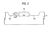
- the supporting substrate 11 is a circular disk-like substrate used to ensure a mechanical strength that is required of the optical recording medium 10.
- a groove 11a and a land 11b for guiding the laser beam 40 are formed spirally on one surface to direct from a near-center portion to an outer peripheral portion or from the outer peripheral portion to the near-center portion.
- the material and a thickness of the supporting substrate 11 are not particularly limited so long as the mechanical strength can be ensured.
- the material of the supporting substrate 11 for example, glass, ceramics, resin, or the like can be used. It is preferable that the resin should be employed if the moldability is considered.
- polycarbonate resin polycarbonate resin, olefin resin, acrylic resin, epoxy resin, polystyrene resin, polyethylene resin, polypropylene resin, silicon resin, fluorinated resin, ABS resin, urethane resin, and the like may be listed.
- the polycarbonate resin or the olefin resin should be employed. In this case, since the supporting substrate 11 does not act as the optical path of the laser beam 40, there is no need that the material with a high light transmittance in that wavelength range should be selected.
- a thickness of the supporting substrate 11 should be set to a necessary and sufficient thickness to ensure a mechanical strength, for example, 0.6 mm or more but 2.0 mm or less. In case the compatibility of this medium with the existing optical recording medium or the next-generation optical recording medium is considered, it is preferable that the thickness should be set to 1.2 mm or less, particularly about 1.1 mm. Also, a diameter of the supporting substrate 11 is not particularly limited. In case the compatibility of this medium with the existing optical recording medium or the next-generation optical recording medium is considered, it is preferable that the diameter should be set to about 120 mm.
- a depth of the groove 11 a is set in excess of ⁇ /8n, preferably should be set to ⁇ /7n or more, where ⁇ is a wavelength of the laser beam 40 and n is a refractive index of the light transmitting layer 12 in the relevant wavelength range.
- ⁇ is a wavelength of the laser beam 40
- n is a refractive index of the light transmitting layer 12 in the relevant wavelength range.
- the depth of the groove 11a may be set to about 34 nm, preferably about 39 nm or more.
- the good signal characteristic, especially a push-pull signal with an enough amplitude can be obtained when the super-resolution recording and the super-resolution reading are executed whereas, if the depth of the groove 11 a is set to ⁇ /7n or more, the better signal characteristic can be obtained when the super-resolution recording and the super-resolution reading are executed.
- an amplitude of the push-pull signal can be maximized by setting the depth of the groove to ⁇ /8n.
- the groove 11 a of the optical recording medium 10 in the present embodiment is set deeper than the depth of the groove in the normal optical recording medium.
- the reason why the push-pull signal with an enough amplitude can be obtained by setting the depth of the groove 11a in excess of ⁇ /8n that is deeper than ordinary one may be mentioned like that, since a bubble generated by local resolution of the noble metal oxide layer 23 is employed as the recording mark in the optical recording medium of the present invention, the substantial groove depth of the recording track can be reduced rather than the groove depth of the unrecorded track. Therefore, it may be concluded that such a phenomenon that the push-pull signal with an enough amplitude can be obtained by setting the depth of the groove 11 a in excess of ⁇ /8n is peculiar to the optical recording medium to which the super-resolution recording and the super-resolution reading can be applied.
- the depth of the groove 11 a should be set to 60 nm or less, and more preferably the depth of the groove 11 a should be set to 50 nm or less.
- a width of the groove 11a should be set narrower than ordinary one.
- the width of the groove should be set to 200 nm or less, particularly 170 nm or less.
- the reason why it is preferable to set the width of the groove 11a narrow is not always clear. But it is guessed that, when the width of the groove 11 a is narrowed, a deformation of the noble metal oxide layer 23 in the horizontal direction can be suppressed by the light transmitting layer 12 positioned over the land 11b and as a result a deformation in the vertical direction is increased to improve the signal characteristic.
- the light transmitting layer 12 is a layer that acts as an optical path of the laser beam 40 that is irradiated at a time of recording and recording.
- the material is not particularly limited as far as such material has a sufficiently high light transmittance in the wavelength range of the employed laser beam 40.
- a light transmissible resin, or the like may be employed.
- a thickness of the light transmitting layer 12 is set to 10 ⁇ m or more but 200 ⁇ m or less.
- the thickness of the light transmitting layer 12 should be set preferably to 50 ⁇ m or more but 250 ⁇ m or less, and more preferably to 70 ⁇ m or more but 120 ⁇ m or less.
- the reflecting layer 21 is a layer that fills the role to not only enhance a read signal level but also improve reproduction stability.
- a single metal such as gold (Au), silver (Ag), copper (Cu), platinum (Pt), aluminum (Al), titanium (Ti), chromium (Cr), iron (Fe), cobalt (Co), nickel (Ni), magnesium (Mg), zinc (Zn), germanium (Ge), or the like or their alloy may be employed.
- a thickness of the reflecting layer 21 is not particularly limited.
- the thickness should be set to 5 nm or more but 200 nm or less, more preferably the thickness should be set to 10 nm or more but 100 nm or less, and most preferably the thickness should be set to 10 nm or more but 50 nm or less. This is because an effect of improving the reproduction stability cannot be sufficiently achieved when the thickness of the reflecting layer 21 is below 5 nm, while it takes much time to form a film and thus productivity is lowered but an effect of improving the reproduction stability can hardly be achieved beyond the above when the thickness of the reflecting layer 21 exceeds 200 nm.
- the thickness of the reflecting layer 21 is set to 10 nm or more but 100 nm or less, particularly 10 nm or more but 50 nm or less, a satisfactory effect of improving the reproduction stability can be achieved not to lower largely the productivity.
- the light absorbing layer 22 is a layer that is considered to function as the "recording layer” in the prior art. Actually this light absorbing layer 22 fills mainly the role to absorb an energy of the laser beam 40 and convert this energy into a heat.
- the material of the light absorbing layer 22 it is preferable that the material that has a large absorption in the wavelength range of the employed laser beam 40 and has a hardness not to interrupt a deformation of the noble metal oxide layer 23 in the recording operation should be employed.
- phase change material used as the material of the recording layer in the rewritable optical recording medium can be listed.
- phase change material preferably either an alloy consisting of antimony (Sb) and tellurium (Te) or the material obtained by adding an additive to this alloy or an alloy consisting of antimony (Sb), tellurium (Te), and germanium (Ge) or the material obtained by adding an additive to this alloy should be employed as a principal component.
- an alloy consisting of antimony (Sb) and tellurium (Te) or the material obtained by adding an additive to this alloy or an alloy consisting of antimony (Sb), tellurium (Te), and germanium (Ge) or the material obtained by adding an additive to this alloy should be employed as a principal component.
- What the wording "as a principal component” intends to mean is that it doesn't matter if a small quantity (15 mol % or less) of other material or an inevitably mixed impurity is contained.
- either the material expressed by ( S b a T e 1 ⁇ a ) 1 ⁇ b M A b where MA is an element except antimony (Sb) and tellurium (Te), 0 ⁇ a ⁇ 1, and 0 ⁇ b ⁇ 1, or the intermetallic compound-based phase change material expressed by ⁇ ( G e T e ) c ( S b 2 T e 3 ) 1 ⁇ c ⁇ d M B 1 ⁇ d where MA is an element except antimony (Sb), tellurium (Te), and germanium (Ge), c 1/3, 1/2 or 2/3, 0 ⁇ d ⁇ 1 may be listed.
- 0 ⁇ a ⁇ 1, and 0 ⁇ b ⁇ 0.15, or 1/3 ⁇ c ⁇ 2/3, and 0.9 ⁇ d should be set.
- a value b exceeds 0.15, it is possible that a light absorption coefficient is degraded lower than a value required for the light absorbing layer 22 and also it is possible that a thermal conductivity is degraded lower than a value required for the light absorbing layer 22. Therefore, this value is not preferable.
- the type of the element MA is not particularly limited. But it is preferable that one or two elements or more selected from a group consisting of germanium (Ge), indium (In), silver (Ag), gold (Au), bismuth (Bi), selenium (Se), aluminum (Al), phosphorus (P), hydrogen (H), silicon (Si), carbon (C), vanadium (V), tungsten (W), tantalum (Ta), zinc (Zn), manganese (Mn), titanium (Ti), tin (Sn), palladium (Pd), lead (Pb), nitrogen (N), oxygen (O), and rare earth elements (scandium (Sc), yttrium (Y), and lanthanoids) should be selected.
- the laser beam having a wavelength of 390 nm to 420 nm when the laser beam having a wavelength of 390 nm to 420 nm is employed, it is preferable that one or two elements or more selected from a group consisting of silver (Ag), germanium (Ge), indium (In), and rare earth elements should be selected as the element MA. Accordingly, the good signal characteristics can be obtained when the laser beam having a wavelength of 390 nm to 420 nm, especially the laser beam having a wavelength of almost 405 nm, is employed.
- the type of the element MB is not particularly limited. But it is preferable that one or two elements or more selected from a group consisting of indium (In), silver (Ag), gold (Au), bismuth (Bi), selenium (Se), aluminum (Al), phosphorus (P), hydrogen (H), silicon (Si), carbon (C), vanadium (V), tungsten (W), tantalum (Ta), zinc (Zn), manganese (Mn), titanium (Ti), tin (Sn), palladium (Pd), lead (Pb), nitrogen (N), oxygen (O), and rare earth elements (scandium (Sc), yttrium (Y), and lanthanoids) should be selected.
- the laser beam having a wavelength of 390 nm to 420 nm when the laser beam having a wavelength of 390 nm to 420 nm is employed, it is preferable that one or two elements or more selected from a group consisting of silver (Ag), indium (In), and rare earth elements should be selected as the element MB. Accordingly, the good signal characteristics can be obtained when the laser beam having a wavelength of 390 nm to 420 nm, especially the laser beam having a wavelength of almost 405 nm, is employed.
- phase change material that is expressed by ( S b a T e 1 ⁇ a ) 1 ⁇ b M A b and satisfies 0 ⁇ a ⁇ 1 should be selected from the above phase change materials, and more preferably the material that satisfies 0 ⁇ a ⁇ 1 and 0 ⁇ b ⁇ 0.15 should be selected.
- the material satisfying the above conditions has a high ductility rather than the intermetallic compound-based phase change material that is expressed by ⁇ ( G e T e ) c ( S b 2 T e 3 ) 1 ⁇ c ⁇ d M B 1 ⁇ d . Therefore, if the foregoing phase change material is employed as a principal component of the light absorbing layer 22, the local deformation of the noble metal oxide layer 23 is not interrupted. As a result, the good signal characteristics can be obtained even when a small recording mark is formed.
- phase change material is employed as the material of the light absorbing layer 22
- the phase change due to a recording operation seldom appears as a signal. It is for this reason that employment of the phase change material as the material of the light absorbing layer 22 is not essential.
- the best signal characteristics can be obtained when the phase change material, especially the phase change material having the above composition, is employed as the material of the light absorbing layer 22.
- a thickness of the light absorbing layer 22 should be set to 5 nm or more but 100 nm or less, more preferably the thickness should be set to 10 nm or more but 80 nm or less, and particularly preferably the thickness should be set to 10 nm or more but 60 nm or less.
- the thickness of the light absorbing layer 22 is set below 5 nm, it is feared that such layer cannot sufficiently absorb an energy of the laser beam 40 and because, when the thickness exceeds 100 nm, it takes much time to form the layer and the productivity is lowered.
- the thickness of the light absorbing layer 22 is set to 10 nm or more but 80 nm or less, particularly 10 nm or more but 60 nm or less, such layer can sufficiently absorb an energy of the laser beam 40 while maintaining the high productivity.
- the present invention it is not essential to provide the light absorbing layer 22 on the optical recording medium. However, as described above, an energy of the laser beam 40 can be effectively converted into a heat when this layer is provided.
- the noble metal oxide layer 23 is a layer on which the recording mark is formed by the irradiation of the laser beam 40, and contains the oxide of the noble metal as a principal component.
- the type of the noble metal is not particularly limited. But at least one type of platinum (Pt), silver (Ag), and palladium (Pd) is preferable, and platinum (Pt) is particularly preferable. That is, it is particularly preferable that platinum oxide (PtOx) should be employed as the material of the noble metal oxide layer 23.
- platinum oxide (PtOx) is employed as the material of the noble metal oxide layer 23, the satisfactory signal characteristics and the sufficient durability can be obtained. It is preferable that, when the platinum oxide (PtOx) is employed as the material of the noble metal oxide layer 23, a value x should be set such that an extinction coefficient (k) is below 3 (k ⁇ 3) in the wavelength range of the employed laser beam 40.
- a thickness of the noble metal oxide layer 23 has a great influence on the signal characteristics.
- the thickness should be set to 2 nm or more but 50 nm or less, and more preferably the thickness should be set to 2 nm or more but 30 nm or less.
- the thickness should be set to 2 nm or more but 8 nm or less, more preferably the thickness should be set to 3 nm or more but 6 nm or less, and most preferably the thickness should be set to about 4 nm.
- the thickness of the noble metal oxide layer 23 is set below 2 nm or in excess of 50 nm, it is feared that the recording mark with a good profile cannot be formed when the laser beam 40 is irradiated and thus a sufficient carrier-to-noise ratio (CNR) cannot be obtained.
- the thickness of the noble metal oxide layer 23 is set to 3 nm or more but 30 nm or less, particularly about 4 nm, the recording mark with a good profile can be formed and also a high CNR can be obtained.
- the dielectric layers 31, 32, and 33 have the role mainly to protect physically and chemically respective layers adjacent to these layers and adjust the optical characteristics.
- the dielectric layers 31, 32, and 33 are also called first, second, and third dielectric layers respectively.
- oxide, sulfide, nitride, or their combination can be employed as a principal component.
- a mixture of ZnS and SiO 2 should be employed.
- a rate of ZnS should be set to 70 mol% or more but 90 mol% or less and a rate of SiO 2 should be set to 10 mol% or more but 30 mol% or less, and most preferably a mole ratio of ZnS and SiO 2 should be set to almost 80:20.
- the dielectric layers 31, 32, and 33 may be composed of the same material mutually, or a part or all of these layers may be composed of different materials. Further, at least one of dielectric layers 31, 32, and 33 may be formed as a multi- layered structure that consists of a plurality of layers.
- a thickness of the dielectric layer 33 should be set to 10 nm or more but 140 nm or less, and more preferably the thickness should be set to 20 nm or more but 120 nm or less. This is because it is possible that the light absorbing layer 22 cannot be sufficiently protected when the thickness of the dielectric layer 33 is below 10 nm whereas much time is required to form the layer and the productivity is lowered when the thickness of the dielectric layer 33 exceeds 140 nm. In contrast, when the thickness of the dielectric layer 33 is set to 20 nm or more but 120 nm or less, the light absorbing layer 22 can be effectively protected while keeping the high productivity.
- a thickness of the dielectric layer 32 should be set to 5 nm or more but 100 nm or less, and more preferably the thickness should be set to 20 nm or more but 100 nm or less. This is because, when the thickness of the dielectric layer 32 is below 5 nm, it is possible that such dielectric layer is broken down during the resolution of the noble metal oxide layer 23 and thus the noble metal oxide layer 23 cannot be protected and because, when the thickness of the dielectric layer 32 exceeds 100 nm, it is possible that the noble metal oxide layer 23 cannot be sufficiently deformed at a time of recording.
- the thickness of the dielectric layer 32 when the thickness of the dielectric layer 32 is set to 20 nm or more but 100 nm or less, the deformation in the recording operation is never excessively interrupted while protecting sufficiently the noble metal oxide layer 23. Also, the thickness of the dielectric layer 32 exerts an influence upon the signal characteristics at a time of reading. When the thickness of the dielectric layer 32 is set to 50 nm or more but 70 nm or less, especially about 60 nm, the high CNR can be obtained.
- a thickness of the dielectric layer 31 may be decided in response to a required reflectance as far as such layer can protect sufficiently the noble metal oxide layer 23.
- the thickness should be set to 30 nm or more but 120 nm or less, more preferably the thickness should be set to 50 nm or more but 100 nm or less, and particularly preferably the thickness should be set to about 70 nm. This is because, when the thickness of the dielectric layer 31 is below 30 nm, it is possible that such dielectric layer cannot sufficiently protect the noble metal oxide layer 23 and because, when the thickness of the dielectric layer 31 exceeds 120 nm, it is possible that it takes much time to form the layer and thus the productivity is lowered. In contrast, when the thickness of the dielectric layer 31 is set to 50 nm or more but 100 nm or less, especially about 70 nm, such dielectric layer can protect sufficiently the noble metal oxide layer 23 while maintaining the high productivity.
- the optical recording medium 10 having such structure, first the supporting substrate 11 is prepared, and then the reflecting layer 21, the dielectric layer 33, the light absorbing layer 22, the dielectric layer 32, the noble metal oxide layer 23, the dielectric layer 31, and the light transmitting layer 12 are formed sequentially on the surface on the side on which the groove 11a and the land 11b are formed. That is, in the manufacture of the optical recording medium 10, respective films are formed sequentially from the opposite side to the light incident plane 12a, like the next-generation optical recording medium.
- the chemical vapor deposition using chemical species containing these constitutive elements e.g., the sputtering method or the vacuum deposition method can be employed. Among them, it is preferable to employ the sputtering method.
- the light transmitting layer 12 for example, an acrylic or epoxy ultraviolet curing resin whose viscosity has been adjusted is coated by the spin coating method, and then the resin is cured by irradiating the ultraviolet rays in a nitrogen atmosphere.
- the light transmitting layer 12 may be formed by using a light transmissible sheet containing a light transmissible resin as a principal component and various adhesives and binders instead of the spin coating method.
- a hard coat layer may be provided on the surface of the light transmitting layer 12 and thus the surface of the light transmitting layer 12 may be protected by this layer.
- the surface of the hard coat layer constitutes the light incident plane 12a.
- the ultraviolet curing resin containing epoxyacrylater oligomer (bifunctional oligomer), multifunctional oligomer, monofunctional acrylic monomer, and photopolymerization initiator, or oxide, nitride, sulfide, carbide, or their mixture of aluminum (Al), silicon (Si), cerium (Ce), titanium (Ti), zinc (Zn), tantalum (Ta), or the like may be employed.
- the ultraviolet curing resin is employed as the material of the hard coat layer, preferably this resin should be formed on the light transmitting layer 12 by the spin coating method.
- the oxide, the nitride, the sulfide, the carbide, or their mixture is employed, the chemical vapor deposition using the chemical seeds containing these constitutive elements, e.g., the sputtering method or the vacuum deposition method can be employed. It is preferable to employ the sputtering method among them.
- an antifouling function should be enhanced by providing lubricity to the hard coat layer to prevent the adhesion of stain.
- a lubricant in the material serving as a mother body of the hard coat layer.
- the lubricant preferably silicon-based lubricant, fluorine-based lubricant, or fatty acid ester-based lubricant should be selected.
- a quantity of content should be set to 0.1 mass % or more but 5.0 mass % or less.
- the data recording onto the optical recording medium 10 is executed by irradiating the laser beam 40, which has a wavelength below 635 nm, especially a wavelength of about 405 nm used in the next-generation optical recording medium, onto the noble metal oxide layer 23 from the light incident plane 12a side, while turning the optical recording medium 10.
- an objective lens having a numerical aperture in excess of 0.6, especially a numerical aperture of about 0.85 used in the next-generation optical recording medium can be employed to converge the laser beam 40. That is, the data recording can be carried out by using the optical system similar to the optical system used in the next-generation optical recording medium.
- Fig.3 is a rough sectional view showing schematically a situation that the laser beam 40 is irradiated onto the optical recording medium 10 along the groove 11a.
- the noble metal oxide layer 23 is resolved at a center portion of the beam spot and then a bubble pit 23a in which an oxygen gas (O 2 ) is filled is formed. Particles 23b of raw metal are scattered in the inside of the bubble pit 23a. At this time, since respective layers existing around the bubble pit 23a are plastically deformed by its pressure, this bubble pit 23a can be employed as the irreversible recording mark.
- O 2 oxygen gas
- this platinum oxide (PtOx) is resolved into the platinum (Pt) and the oxygen gas (O 2 ) at the center portion of the beam spot, and then the particles of the platinum (Pt) are scattered into the bubble pit 23a.
- the plastic deformation is generated on the supporting substrate 11 side, i.e., on the light absorbing layer 22 in the horizontal direction, as shown in Fig.3, but the plastic deformation is hardly generated on the light transmitting layer 12 side. This is because the light absorbing layer 22 absorbs the light and converts this light into a heat and then this heat causes the resolving reaction of the noble metal oxide layer 23.
- a width of the groove 11 a is set narrow, the deformation in the horizontal direction is suppressed by a wall surface portion 12b of the light transmitting layer 12 and as a result the deformation in the vertical direction can be increased. Since the signal characteristics in the super-resolution optical recording medium according to the present invention become better as the deformation in the vertical direction is increased larger, such signal characteristics can be improved by setting the width of the groove 11a narrowly.
- the resolution of the noble metal oxide layer 23 is generated not in the overall beam spot but at the center portion of the beam spot only, as described above. Therefore, the formed bubble pit 23 a (recording mark) is small in contrast to a beam spot diameter, and accordingly the super-resolution recording can be realized.
- the reason why such super- resolution recording can be executed will be given as follows.
- Fig.4(a) is a plan view showing a beam spot of the laser beam 40 on the noble metal oxide layer 23
- Fig.4(b) is a view showing an intensity distribution of the beam spot.
- a planar shape of a beam spot 41 is almost circular, but the intensity distribution of the laser beam 40 in the beam spot 41 is not uniform and has a Gaussian distribution as shown in Fig.4(b). That is, the beam spot 41 has a higher energy toward its center portion. Consequently, if a predetermined threshold value A that exceeds sufficiently a maximum intensity 1/e 2 is set, a diameter W2 of an area 42 that has an intensity in excess of the threshold value A becomes sufficiently smaller than a diameter W1 of the beam spot 41.
- the bubble pit 23 a (recording mark) can be formed selectively only in the portion, on which the laser beam 40 is irradiated and which corresponds to the area 42 of the beam spot 41.
- the bubble pit 23 a (recording mark) that is sufficiently smaller than the diameter W1 of the beam spot can be formed in the noble metal oxide layer 23 and its diameter becomes almost W2. That is, a relationship between the apparent beam spot diameter W2 and the actual beam spot diameter W 1 is given by W 1 > W 2 and the super-resolution recording can be realized.
- the platinum oxide (PtOx) that is the most desirable material as the material of the noble metal oxide layer 23 has such a characteristic that this platinum oxide is decomposed when it is heated at 580 °C, the intensity at which the noble metal oxide layer 23 is heated up to 580 °C or more by the irradiation gives the threshold value A.
- the material the above thermal conductivity of which is high to some extent is selected as the material of the dielectric layer 32, the area whose temperature exceeds 580 °C is not excessively expanded. As a result, the small recording mark with a good shape can be formed.
- the fine recording mark whose size is below the reading limit can be formed in a desired portion of the noble metal oxide layer 23.
- Fig.6 is a waveform diagram showing an example of an intensity modulation pattern of the laser beam 40 at a time of recording.
- Pw1 a recording power
- Pb ground power
- the recording marks M1, M2, M3... each having a desired length can be formed.
- the intensity modulation pattern of the laser beam 40 at a time of recording is not limited to the pattern shown in Fig.6.
- the recording marks M1, M2, M3... may be formed by using the multi pulse train.
- Fig. 8 is a graph showing schematically a relationship between a recording power of the laser beam 40 and CNR of a read signal obtained by the later readout.
- the recording power of the laser beam 40 when the recording power of the laser beam 40 is below Pw1, an effective read signal cannot be obtained in the optical recording medium 10 by the later readout.
- the reason for this may be considered such that the noble metal oxide layer 23 is not substantially resolved when the recording power of the laser beam 40 is below Pw1.
- the higher recording power can give the higher CNR in the later readout.
- the reason for this may be considered such that the resolution of the noble metal oxide layer 23 is generated partially in the area in which the recording power of the laser beam 40 is Pw1 or more but below Pw2, so that a quantity of resolution becomes larger as the recording power goes higher.
- the CNR obtained by the later readout is seldom changed even when the recording power is increased further more.
- the reason for this may be considered such that, when the recording power of the laser beam 40 is set to Pw2 or more, the noble metal oxide layer 23 is substantially completely resolved. With the above, it is possible to say that preferably the recording power of the laser beam 40 should be set to Pw2 or more.
- the value Pw2 is different depending upon a structure of the optical recording medium 10 (material of respective layers, thickness of respective layers, and the like) and recording conditions (recording linear velocity, wavelength of the laser beam 40, and the like).
- the recording linear velocity is about 6.0 m/s
- the wavelength of the laser beam 40 is about 405 nm
- the numerical aperture of the objective lens 50 is about 0.85, 5.0 mW ⁇ Pw2 ⁇ 9.0 mW.
- Pw1 ⁇ 1.4 ⁇ Pw2 ⁇ Pw1 ⁇ 2.0 is given in connection with Pw1.
- the reason why such super-resolution reading can be realized is not always clear, but it is guessed that, when the laser beam 40 that is set to the reading power is irradiated, any interaction is caused between the laser beam 40 and the metal particles 23b existing in the bubble pit 23 a to make the super-resolution reading possible.
- Fig. 9 is a graph showing schematically a relationship between the reading power of the laser beam 40 and the CNR.
- the reading power of the laser beam 40 should be set to Pr2 or more but below Pw1.
- the value Pr2 is different depending upon a structure of the optical recording medium 10 (material of respective layers, thickness of respective layers, and the like) and reading conditions (reading linear velocity, wavelength of the laser beam 40, and the like).
- the reading linear velocity is about 6.0 m/s
- the wavelength of the laser beam 40 is about 405 nm
- the numerical aperture of the objective lens 50 is about 0.85, 1.0 mW ⁇ Pr2 ⁇ 3.0 mW.
- Pr1 ⁇ 1.05 ⁇ Pr2 ⁇ Pr1 ⁇ 1.6 is given in connection with Pr1.
- the reading power in the optical recording medium in the prior art is about 0.1 mW to 0.5 mW, and such a situation hardly takes place in the next-generation optical recording medium, which has two recording planes on one side, that the reading power is set in excess of about 0.8 mW.
- a reading power level in the present embodiment is considerably high rather than the optical recording medium in the prior art.
- the actual reading power should be set to Pw ⁇ 0.1 ⁇ Pr ⁇ Pw ⁇ 0.5 in connection with the actual recording power, and more preferably the actual reading power should be set to Pw ⁇ 0.1 ⁇ Pr ⁇ Pw ⁇ 0.4. From this respect, it is also understood that a reading power level in the present embodiment is considerably high rather than the optical recording medium in the prior art.
- respective values to be set actually as the recording power and the reading power should be saved in the concerned optical recording medium 10 as "set information". If the set information are saved in the optical recording medium 10, such set information are read by the optical recording/reading system when the user records or reads actually the data and then the recording power and the reading power can be decided based on the set information.
- the set information may be included as the set information.
- Such set information may be recorded as the wobble or the prebit, or may be recorded as the data on the noble metal oxide layer 23.
- the information indicating directly various conditions required to record or read the data but also the information indicating indirectly the recording power and the reading power, and others by designating any of various conditions stored previously in the optical recording/reading system may be provided.
- ⁇ /NA can be set to 640 nm or less by employing the laser beam having a wavelength below about 635 nm and the objective lens having the numerical aperture in excess of about 0.6, and thus the super-resolution recording and the super-resolution reading can be carried out.
- the excellent characteristics can be obtained in the super-resolution recording and the super-resolution reading using the laser beam having a wavelength of about 405 nm and the objective lens having the numerical aperture of about 0.85, both are employed in the next-generation optical recording medium. Accordingly, since the recording/reading system similar to the recording/reading system for the next-generation optical recording medium can be employed, a development cost and a production cost of the recording/reading system can be suppressed.
- a depth Gd of the groove 11 a formed on the supporting substrate 11 is set in excess of ⁇ /8n, preferably set to ⁇ /7n or more, the good signal characteristic, especially the push- pull signal with an enough amplitude, can be obtained in the super-resolution recording and the super-resolution reading. A possibility that the optical recording medium is out of tracking can be largely reduced.
- a width Gw of the groove 11a is set narrower than the ordinary width, the deformation of the noble metal oxide layer 23 caused by the recording in the vertical direction can be increased and thus the signal characteristics can be improved much more.
- the structure of the optical recording medium 10 shown in Fig. 1 merely illustrates the favorable structure of the optical recording medium according to the present invention, and the structure of the optical recording medium according to the present invention is not limited to the above structure.
- one more noble metal oxide layer may be added to the supporting substrate 11 side when viewed from the light absorbing layer 22, otherwise one more phase change material layer may added to the light transmitting layer 12 side when viewed from the noble metal oxide layer 23.
- the structure having the recording surface on both sides can be formed by providing various function layers such as the light absorbing layer 22, the noble metal oxide layer 23, and the like on both surfaces of the supporting substrate 11 respectively, otherwise the structure having two layers or more of recording surfaces on one side can be formed by stacking two layers or more of various function layers on one surface of the supporting substrate 11 via a transparent intermediate layer.
- the optical recording medium 10 shown in Fig. 1 has the structure that has a high compatibility with the so-called next-generation optical recording medium. It is possible to provide the structure that has a high compatibility with the so-called DVD optical recording medium or the CD optical recording medium
- the noble metal oxide layer 23 is employed as the recording layer serving as a generation source of the bubble pit 23a, but a noble metal nitride layer may be employed in place of the noble metal oxide layer.
- a noble metal nitride layer may be employed in place of the noble metal oxide layer.
- platinum (Pt) is particularly preferable as the type of the noble metal, and platinum (Pt) is particularly preferable. That is, it is particularly preferable that platinum nitride (PtNx) should be selected.
- the bubble pit 23 a is formed by a nitrogen gas (N 2 ) generated by the resolution. Since the nitrogen gas (N 2 ) is a very chemically stable gas, there is no chance that other layers are oxidized or eroded by this gas and therefore high saving reliability can be achieved.
- the noble metal oxide layer 23 is put between the dielectric layers 31, 32.
- the dielectric layer 31 can be omitted.
- Samples of the optical recording medium having the same structure as the optical recording medium 10 shown in Fig. 1 were manufactured by the following method.
- a depth Gd of the groove 11 a was set to about 41 nm, and a width Gw of the groove 11a was set to about 169 nm.
- a track pitch was set to about 320 nm.
- the supporting substrate 11 was loaded in the sputtering equipment.
- the reflecting layer 21 made substantially of platinum (Pt) and having a thickness of about 20 nm
- the light absorbing layer 22 made of the phase change material represented substantially by Sb 74.1 Te 25.9 (subscript values are % representation.
- the noble metal oxide layer 23 made substantially of platinum oxide (PtOx) and having a thickness of about 4 nm
- the acrylic ultraviolet curing resin was coated on the dielectric layer 31 by the spin coating method, and then the light transmitting layer 12 having a thickness of about 100 ⁇ m was formed by irradiating the ultraviolet rays onto this resin. Accordingly, the sample of the optical recording medium in Example 1 was completed.
- a sample of the optical recording medium according to Example 2 was manufactured by the similar way to the sample of the optical recording medium according to Example 1, except that the substrate on which the width Gw of the groove 11a is set to about 181 nm was used as the supporting substrate 11.
- a sample of the optical recording medium according to Example 3 was manufactured by the similar way to the sample of the optical recording medium according to Example 1, except that the substrate on which the width Gw of the groove 11 a is set to about 197 nm was used as the supporting substrate 11.
- a sample of the optical recording medium according to Example 4 was manufactured by the similar way to the sample of the optical recording medium according to Example 1, except that the substrate on which the width Gw of the groove 11a is set to about 208 nm was used as the supporting substrate 11.
- a sample of the optical recording medium according to Example 5 was manufactured by the similar way to the sample of the optical recording medium according to Example 1, except that the substrate on which the width Gw of the groove 11a is set to about 214 nm was used as the supporting substrate 11.
- a sample of the optical recording medium according to Example 7 was manufactured by the similar way to the sample of the optical recording medium according to Example 6, except that the substrate on which the width Gw of the groove 11a is set to about 181 nm was used as the supporting substrate 11.
- a sample of the optical recording medium according to Example 8 was manufactured by the similar way to the sample of the optical recording medium according to Example 6, except that the substrate on which the width Gw of the groove 11a is set to about 191 nm was used as the supporting substrate 11.
- a sample of the optical recording medium according to Example 9 was manufactured by the similar way to the sample of the optical recording medium according to Example 6, except that the substrate on which the width Gw of the groove 11a is set to about 201 nm was used as the supporting substrate 11.
- a sample of the optical recording medium according to Example 10 was manufactured by the similar way to the sample of the optical recording medium according to Example 6, except that the substrate on which the width Gw of the groove 11a is set to about 212 nm was used as the supporting substrate 11.
- a sample of the optical recording medium according to Comparative Example 2 was manufactured by the similar way to the sample of the optical recording medium according to Comparative Example 1, except that the substrate on which the width Gw of the groove 11a is set to about 193 nm was used as the supporting substrate 11.
- a sample of the optical recording medium according to Comparative Example 3 was manufactured by the similar way to the sample of the optical recording medium according to Comparative Example 1, except that the substrate on which the width Gw of the groove 11 a is set to about 200 nm was used as the supporting substrate 11.
- a sample of the optical recording medium according to Comparative Example 4 was manufactured by the similar way to the sample of the optical recording medium according to Comparative Example 1, except that the substrate on which the width Gw of the groove 11a is set to about 208 nm was used as the supporting substrate 11.
- a sample of the optical recording medium according to Comparative Example 5 was manufactured by the similar way to the sample of the optical recording medium according to Comparative Example 1, except that the substrate on which the width Gw of the groove 11a is set to about 209 nm was used as the supporting substrate 11.
- Example 1 the samples of the optical recording mediums in Example 1, Example 3, and Example 5 were set on the optical disk evaluation system (DDU1000 manufactured by Pulse Tech Co., Ltd.). Then, while turning the sample at a linear velocity of about 4.9 m/s, a single frequency signal the recording mark length and the blank length of which are 75 nm was recorded by irradiating the laser beam whose wavelength is about 405 nm onto the noble metal oxide layer 23 from the light incident plane 12a via the objective lens having the numerical aperture of about 0.85.
- the reading limit given by d 2 ⁇ /4NA was about 120 nm.
- the recording power (Pw) was set variously and the ground power (Pb) was set to almost 0 mW. Also, the pattern shown in Fig. 6 was used as a pulse pattern of the laser beam 40.
- the reading power (Pr) of the laser beam 40 was set to 2.6 mW, 2.8 mW, and 2.8 mW in the samples of the optical recording mediums in Example 1, Example 3, and Example 5 respectively. Measurement results of the CNR are shown in Fig.10.
- the recording power (Pw) was set variously and the ground power (Pb) was set to almost 0 mW. Also, the pattern shown in Fig.6 was used as the pulse pattern of the laser beam 40.
- the reading power (Pr) of the laser beam 40 was set to 2.6 mW, 2.8 mW, and 3.0 mW in the samples of the optical recording mediums in Example 6, Example 8, and Example 10 respectively. Measurement results of the CNR are shown in Fig.11.
- the recording power margin was relatively wide and the CNR in excess of 37 dB could be obtained at its maximum.
- the maximum value of the CNR was better in the sample in which the width Gw of the groove 11a was set narrower.
- the recording power margin was wider in the sample in which the width Gw of the groove 11a was set narrower.
- the recording power (Pw) was set variously and the ground power (Pb) was set to almost 0 mW. Also, the pattern shown in Fig.6 was used as the pulse pattern of the laser beam 40.
- the reading power (Pr) of the laser beam 40 was set to 2.6 mW, 2.8 mW, and 2.6 mW in the samples of the optical recording mediums in Comparative Example 1, Comparative Example 2, and Comparative Example 4 respectively. Measurement results of the CNR are shown in Fig.12.
- the high CNR could be obtained as the maximum value.
- the recording power (Pw) is increased, the optical recording medium is easily out of tracking and the recording could not be executed. For this reason, the recording power margin was extremely narrow, and it was difficult to put these samples into practical use.
- the single frequency signals recorded in “the characteristic evaluation 1” were read by using various reading powers, and their CNR was measured. Measurement results of the CNR are shown in Fig.13.
- the single frequency signals recorded in “the characteristic evaluation 2” were read by using various reading powers, and their CNR was measured. Measurement results of the CNR are shown in Fig.14.
- the reading power margin was sufficiently wide and the CNR in excess of 39 dB could be obtained at its maximum. Also, the maximum value of the CNR was better in the sample in which the width Gw of the groove 11a was set narrower.
- the high CNR could be obtained as the maximum value.
- the reading power (Pr) is increased, the optical recording medium is easily out of tracking and the reading could not be executed. For this reason, the reading power margin was extremely narrow, and it was difficult to put these samples into practical use.
- the samples of the optical recording mediums in Examples 1 to 10 and Comparative Examples 1 to 5 were set on the optical disk evaluation system. Then, the laser beam whose wavelength is about 405 nm was irradiated onto the unrecorded track from the light incident plane 12a via the objective lens having the numerical aperture of about 0.85 while turning the sample at the linear velocity of about 4.9 m/s, and then a resultant push-pull signal was measured and also a normalized value (NPP) of this signal was calculated. The power of the laser beam was set to 0.4 mW in all the samples of the optical recording mediums.
- the normalized value (NPP) of the push-pull signal is defined by a difference between the maximum value and the minimum value of a value given by (I 1 -I 2 )/(I 1 +I 2 ).
- the samples of the optical recording mediums in Examples 1 to 10 and Comparative Examples 1 to 5 were set on the optical disk evaluation system. Then, the single frequency signal the recording mark length and the blank length of which are 75 nm was recorded under the same conditions as in "the characteristic evaluation 1".
- the recording power (Pw) and the ground power (Pb) of the laser beam 40 at a time of recording were set to 8.0 mW and almost 0 mW respectively in all the samples of the optical recording mediums. Also, the pattern shown in Fig.6 was used as the pulse pattern of the laser beam 40.
- the laser beam is irradiated onto the track on which the single frequency signal was recorded, and then the resultant push-pull signal was measured and also the normalized value (NPP) of this signal was calculated.
- the power of the laser beam was set to 0.4 mW in all the samples of the optical recording mediums, as in "the characteristic evaluation 7".
- an optical recording medium whose signal characteristics at a time of super- resolution recording and super-resolution reading are improved, and a method of manufacturing the same are provided. Also, a method of recording data on an optical recording medium whose signal characteristics at a time of super-resolution recording and super-resolution reading are improved, and a method of reading the data from such optical recording medium, by using a laser beam having a shorter wavelength and an objective lens having a larger numerical aperture are provided.
Applications Claiming Priority (2)
| Application Number | Priority Date | Filing Date | Title |
|---|---|---|---|
| JP2003312104A JP2005078782A (ja) | 2003-09-04 | 2003-09-04 | 光記録媒体及びその製造方法、並びに、光記録媒体に対するデータ記録方法及びデータ再生方法 |
| PCT/JP2004/013004 WO2005024799A1 (fr) | 2003-09-04 | 2004-09-01 | Support d'enregistrement optique, son procede de fabrication, procede d'enregistrement de donnees sur un support d'enregistrement optique, et procede de reproduction de donnees |
Publications (2)
| Publication Number | Publication Date |
|---|---|
| EP1662489A1 true EP1662489A1 (fr) | 2006-05-31 |
| EP1662489A4 EP1662489A4 (fr) | 2008-07-16 |
Family
ID=34269730
Family Applications (1)
| Application Number | Title | Priority Date | Filing Date |
|---|---|---|---|
| EP04772876A Withdrawn EP1662489A4 (fr) | 2003-09-04 | 2004-09-01 | Support d'enregistrement optique, son procede de fabrication, procede d'enregistrement de donnees sur un support d'enregistrement optique, et procede de reproduction de donnees |
Country Status (7)
| Country | Link |
|---|---|
| US (1) | US20070030795A1 (fr) |
| EP (1) | EP1662489A4 (fr) |
| JP (1) | JP2005078782A (fr) |
| KR (1) | KR100770808B1 (fr) |
| CN (1) | CN100411024C (fr) |
| TW (1) | TWI276098B (fr) |
| WO (1) | WO2005024799A1 (fr) |
Families Citing this family (24)
| Publication number | Priority date | Publication date | Assignee | Title |
|---|---|---|---|---|
| JP2005022196A (ja) * | 2003-07-01 | 2005-01-27 | Tdk Corp | 光記録ディスク |
| JP2005025842A (ja) * | 2003-07-01 | 2005-01-27 | Tdk Corp | 光記録ディスク |
| JP2005025841A (ja) * | 2003-07-01 | 2005-01-27 | Tdk Corp | 光記録ディスク |
| JP2005044438A (ja) * | 2003-07-22 | 2005-02-17 | Tdk Corp | 光記録ディスク |
| JP2005129181A (ja) * | 2003-10-27 | 2005-05-19 | National Institute Of Advanced Industrial & Technology | 光記録ディスク |
| US7235501B2 (en) | 2004-12-13 | 2007-06-26 | Micron Technology, Inc. | Lanthanum hafnium oxide dielectrics |
| US7560395B2 (en) | 2005-01-05 | 2009-07-14 | Micron Technology, Inc. | Atomic layer deposited hafnium tantalum oxide dielectrics |
| US8859184B2 (en) * | 2005-07-28 | 2014-10-14 | Ricoh Company, Ltd. | Write-once-read-many optical disk having low-to-high recording property accommodating short wavelength recording |
| KR20070017759A (ko) * | 2005-08-08 | 2007-02-13 | 삼성전자주식회사 | 초해상 정보 저장 매체, 기록/재생 장치 및 기록/재생 방법 |
| US7410910B2 (en) * | 2005-08-31 | 2008-08-12 | Micron Technology, Inc. | Lanthanum aluminum oxynitride dielectric films |
| JP4782189B2 (ja) * | 2006-03-03 | 2011-09-28 | シャープ株式会社 | 光情報記録媒体及び再生装置 |
| US7432548B2 (en) * | 2006-08-31 | 2008-10-07 | Micron Technology, Inc. | Silicon lanthanide oxynitride films |
| US20080057659A1 (en) * | 2006-08-31 | 2008-03-06 | Micron Technology, Inc. | Hafnium aluminium oxynitride high-K dielectric and metal gates |
| US7759747B2 (en) | 2006-08-31 | 2010-07-20 | Micron Technology, Inc. | Tantalum aluminum oxynitride high-κ dielectric |
| US7605030B2 (en) | 2006-08-31 | 2009-10-20 | Micron Technology, Inc. | Hafnium tantalum oxynitride high-k dielectric and metal gates |
| US7776765B2 (en) | 2006-08-31 | 2010-08-17 | Micron Technology, Inc. | Tantalum silicon oxynitride high-k dielectrics and metal gates |
| US7563730B2 (en) * | 2006-08-31 | 2009-07-21 | Micron Technology, Inc. | Hafnium lanthanide oxynitride films |
| US7544604B2 (en) * | 2006-08-31 | 2009-06-09 | Micron Technology, Inc. | Tantalum lanthanide oxynitride films |
| JP2008142895A (ja) * | 2006-12-05 | 2008-06-26 | Fujifilm Corp | モールド構造体 |
| US20080170485A1 (en) * | 2007-01-15 | 2008-07-17 | Tdk Corporation | Optical recording medium |
| JP4903081B2 (ja) * | 2007-05-17 | 2012-03-21 | 株式会社日立製作所 | 光ディスク媒体及びトラッキング方法 |
| US8223620B2 (en) | 2007-08-30 | 2012-07-17 | Sharp Kabushiki Kaisha | Super-resolution optical recording medium on which information is recorded using train of prepits, optical recording medium reproduction device, and control method |
| JP2013242953A (ja) * | 2012-04-26 | 2013-12-05 | Sony Corp | 光情報記録媒体 |
| WO2014119588A1 (fr) * | 2013-02-04 | 2014-08-07 | 三菱電機株式会社 | Support d'enregistrement d'informations optiques et dispositif d'enregistrement/de reproduction |
Citations (2)
| Publication number | Priority date | Publication date | Assignee | Title |
|---|---|---|---|---|
| JPS63299984A (ja) * | 1987-05-30 | 1988-12-07 | Kuraray Co Ltd | 光記録媒体及びその製造法 |
| WO2003003362A1 (fr) * | 2001-06-29 | 2003-01-09 | Sony Corporation | Support d'enregistrement/reproduction optique, matrice mere pour la production d'un support d'enregistrement/reproduction optique et dispositif d'enregistrement/reproduction optique |
Family Cites Families (12)
| Publication number | Priority date | Publication date | Assignee | Title |
|---|---|---|---|---|
| JPH06262854A (ja) * | 1993-03-15 | 1994-09-20 | Konica Corp | 光記録媒体 |
| JP2001357534A (ja) * | 2000-04-10 | 2001-12-26 | Victor Co Of Japan Ltd | 情報記録媒体 |
| JP2002008269A (ja) * | 2000-06-22 | 2002-01-11 | Sony Corp | 光学記録媒体およびその製造方法 |
| JP4265861B2 (ja) * | 2000-06-30 | 2009-05-20 | 独立行政法人産業技術総合研究所 | 光学読み取り・書き込み方法、情報記録媒体、及び光学装置 |
| JP2002150614A (ja) * | 2000-11-10 | 2002-05-24 | Pioneer Electronic Corp | 光ディスク |
| US7133331B2 (en) * | 2000-12-28 | 2006-11-07 | Victor Company Of Japan, Limited | Recording medium having a substrate containing microscopic pattern of parallel groove and land sections and recording/reproducing equipment therefor |
| JP4582755B2 (ja) * | 2002-06-24 | 2010-11-17 | Tdk株式会社 | 光記録/再生方法および光記録媒体 |
| JP2005025899A (ja) * | 2003-07-01 | 2005-01-27 | Tdk Corp | 光記録媒体及びその製造方法、並びに、光記録媒体に対するデータ記録方法及びデータ再生方法 |
| JP2005025900A (ja) * | 2003-07-01 | 2005-01-27 | Tdk Corp | 光記録媒体、光記録再生装置、光記録装置及び光再生装置、並びに、光記録媒体に対するデータ記録再生方法、データ記録方法及びデータ再生方法 |
| JP2005044450A (ja) * | 2003-07-24 | 2005-02-17 | Tdk Corp | 光記録媒体及びその製造方法、並びに、光記録媒体に対するデータ記録方法及びデータ再生方法 |
| JP4167146B2 (ja) * | 2003-08-19 | 2008-10-15 | Tdk株式会社 | 光記録媒体及びその製造方法、並びに、光記録媒体に対するデータ記録方法及びデータ再生方法 |
| JP2005071450A (ja) * | 2003-08-22 | 2005-03-17 | Tdk Corp | 光記録媒体及びその製造方法、並びに、光記録媒体に対するデータ記録方法及びデータ再生方法 |
-
2003
- 2003-09-04 JP JP2003312104A patent/JP2005078782A/ja active Pending
-
2004
- 2004-09-01 EP EP04772876A patent/EP1662489A4/fr not_active Withdrawn
- 2004-09-01 KR KR1020067004504A patent/KR100770808B1/ko not_active IP Right Cessation
- 2004-09-01 US US10/570,659 patent/US20070030795A1/en not_active Abandoned
- 2004-09-01 WO PCT/JP2004/013004 patent/WO2005024799A1/fr not_active Application Discontinuation
- 2004-09-01 CN CNB2004800252721A patent/CN100411024C/zh not_active Expired - Fee Related
- 2004-09-03 TW TW093126669A patent/TWI276098B/zh active
Patent Citations (2)
| Publication number | Priority date | Publication date | Assignee | Title |
|---|---|---|---|---|
| JPS63299984A (ja) * | 1987-05-30 | 1988-12-07 | Kuraray Co Ltd | 光記録媒体及びその製造法 |
| WO2003003362A1 (fr) * | 2001-06-29 | 2003-01-09 | Sony Corporation | Support d'enregistrement/reproduction optique, matrice mere pour la production d'un support d'enregistrement/reproduction optique et dispositif d'enregistrement/reproduction optique |
Non-Patent Citations (3)
| Title |
|---|
| KIKUKAWA T ET AL: "Rigid bubble pit formation and huge signal enhancement in super-resolution near field structure disk with platinum-oxide layer" APPLIED PHYSICS LETTERS, AIP, AMERICAN INSTITUTE OF PHYSICS, MELVILLE, NY, vol. 81, no. 25, 16 December 2002 (2002-12-16), pages 4697-4699, XP002458620 ISSN: 0003-6951 * |
| KIM JOOHO ET AL: "Super-resolution by elliptical bubble formation with PtOx and AgInSbTe layers" APPLIED PHYSICS LETTERS, AIP, AMERICAN INSTITUTE OF PHYSICS, MELVILLE, NY, vol. 83, no. 9, 1 September 2003 (2003-09-01), pages 1701-1703, XP012035922 ISSN: 0003-6951 * |
| See also references of WO2005024799A1 * |
Also Published As
| Publication number | Publication date |
|---|---|
| WO2005024799A1 (fr) | 2005-03-17 |
| EP1662489A4 (fr) | 2008-07-16 |
| TW200514072A (en) | 2005-04-16 |
| CN1846254A (zh) | 2006-10-11 |
| KR20060033047A (ko) | 2006-04-18 |
| KR100770808B1 (ko) | 2007-10-26 |
| TWI276098B (en) | 2007-03-11 |
| US20070030795A1 (en) | 2007-02-08 |
| CN100411024C (zh) | 2008-08-13 |
| JP2005078782A (ja) | 2005-03-24 |
Similar Documents
| Publication | Publication Date | Title |
|---|---|---|
| EP1662489A1 (fr) | Support d'enregistrement optique, son procede de fabrication, procede d'enregistrement de donnees sur un support d'enregistrement optique, et procede de reproduction de donnees | |
| EP1650752A1 (fr) | Support d'enregistrement optique et procede de production associe, procede d'enregistrement de donnees et procede de reproduction de donnees pour support d'enregistrement optique | |
| EP1640977A1 (fr) | Support d'enregistrement optique, enregistreur/lecteur optique, enregistreur optique et lecteur optique, procede d'enregistrement/lecture de donnees pour support d'enregistrement optique, et procede d'enregistrement et de lecture de donnees | |
| KR100685061B1 (ko) | 광기록매체 및 이를 제조하기 위한 방법, 및 광기록매체상에 데이터를 기록하기 위한 방법 및 광기록매체로부터데이터를 재생하는 방법 | |
| JP4167146B2 (ja) | 光記録媒体及びその製造方法、並びに、光記録媒体に対するデータ記録方法及びデータ再生方法 | |
| KR100770807B1 (ko) | 광기록매체 및 이를 제조하는 방법, 광기록매체에 대한데이터기록방법 및 데이터재생방법 | |
| WO1999030908A1 (fr) | Element d'enregistrement inscriptible une fois de donnees optiques | |
| EP1657717A1 (fr) | Disque d'enregistrement optique | |
| JP2003326848A (ja) | 追記型光記録媒体 | |
| JP4064967B2 (ja) | 記録型光ディスクの製造方法、前記方法により得られる光ディスク、および記録層 | |
| JP2004284018A (ja) | 光記録媒体 | |
| JP2008090964A (ja) | 追記型2層構成光記録媒体 | |
| JPH09263055A (ja) | スパッタリング用ターゲット、その製造方法、そのターゲットを用いた光記録媒体、その光記録媒体の製造方法、及び光記録方法 | |
| JP2002337451A (ja) | 光記録媒体 | |
| JP2004227720A (ja) | 光記録媒体 | |
| WO2006036123A1 (fr) | Support d'enregistrement | |
| KR19990068998A (ko) | 추기형 광기록 매체 |
Legal Events
| Date | Code | Title | Description |
|---|---|---|---|
| PUAI | Public reference made under article 153(3) epc to a published international application that has entered the european phase |
Free format text: ORIGINAL CODE: 0009012 |
|
| 17P | Request for examination filed |
Effective date: 20060303 |
|
| AK | Designated contracting states |
Kind code of ref document: A1 Designated state(s): AT BE BG CH CY CZ DE DK EE ES FI FR GB GR HU IE IT LI LU MC NL PL PT RO SE SI SK TR |
|
| DAX | Request for extension of the european patent (deleted) | ||
| STAA | Information on the status of an ep patent application or granted ep patent |
Free format text: STATUS: THE APPLICATION HAS BEEN WITHDRAWN |
|
| A4 | Supplementary search report drawn up and despatched |
Effective date: 20080616 |
|
| 18W | Application withdrawn |
Effective date: 20080625 |