EP1662272A1 - Method and system for detecting with a radar the passage of a vehicle at a point to be monitored on a road - Google Patents
Method and system for detecting with a radar the passage of a vehicle at a point to be monitored on a road Download PDFInfo
- Publication number
- EP1662272A1 EP1662272A1 EP05077044A EP05077044A EP1662272A1 EP 1662272 A1 EP1662272 A1 EP 1662272A1 EP 05077044 A EP05077044 A EP 05077044A EP 05077044 A EP05077044 A EP 05077044A EP 1662272 A1 EP1662272 A1 EP 1662272A1
- Authority
- EP
- European Patent Office
- Prior art keywords
- vehicle
- point
- monitoring
- transmitting
- distance
- Prior art date
- Legal status (The legal status is an assumption and is not a legal conclusion. Google has not performed a legal analysis and makes no representation as to the accuracy of the status listed.)
- Granted
Links
- 238000000034 method Methods 0.000 title claims abstract description 25
- 238000001514 detection method Methods 0.000 claims abstract description 48
- 238000012544 monitoring process Methods 0.000 claims abstract description 43
- 230000001154 acute effect Effects 0.000 claims abstract description 7
- 230000003213 activating effect Effects 0.000 claims description 18
- 230000006698 induction Effects 0.000 abstract description 3
- 238000005259 measurement Methods 0.000 description 12
- 238000012937 correction Methods 0.000 description 6
- 238000012546 transfer Methods 0.000 description 5
- 238000004891 communication Methods 0.000 description 4
- 238000012986 modification Methods 0.000 description 2
- 230000004048 modification Effects 0.000 description 2
- 239000007787 solid Substances 0.000 description 2
- 238000013459 approach Methods 0.000 description 1
- 230000005540 biological transmission Effects 0.000 description 1
- 239000004020 conductor Substances 0.000 description 1
- 238000005520 cutting process Methods 0.000 description 1
- 230000007423 decrease Effects 0.000 description 1
- 230000001419 dependent effect Effects 0.000 description 1
- 230000005672 electromagnetic field Effects 0.000 description 1
- 230000001939 inductive effect Effects 0.000 description 1
- 239000002184 metal Substances 0.000 description 1
- 238000012545 processing Methods 0.000 description 1
- 230000000750 progressive effect Effects 0.000 description 1
- 230000005855 radiation Effects 0.000 description 1
Images

Classifications
-
- G—PHYSICS
- G01—MEASURING; TESTING
- G01S—RADIO DIRECTION-FINDING; RADIO NAVIGATION; DETERMINING DISTANCE OR VELOCITY BY USE OF RADIO WAVES; LOCATING OR PRESENCE-DETECTING BY USE OF THE REFLECTION OR RERADIATION OF RADIO WAVES; ANALOGOUS ARRANGEMENTS USING OTHER WAVES
- G01S13/00—Systems using the reflection or reradiation of radio waves, e.g. radar systems; Analogous systems using reflection or reradiation of waves whose nature or wavelength is irrelevant or unspecified
- G01S13/88—Radar or analogous systems specially adapted for specific applications
- G01S13/91—Radar or analogous systems specially adapted for specific applications for traffic control
- G01S13/92—Radar or analogous systems specially adapted for specific applications for traffic control for velocity measurement
-
- G—PHYSICS
- G08—SIGNALLING
- G08G—TRAFFIC CONTROL SYSTEMS
- G08G1/00—Traffic control systems for road vehicles
- G08G1/01—Detecting movement of traffic to be counted or controlled
-
- G—PHYSICS
- G01—MEASURING; TESTING
- G01S—RADIO DIRECTION-FINDING; RADIO NAVIGATION; DETERMINING DISTANCE OR VELOCITY BY USE OF RADIO WAVES; LOCATING OR PRESENCE-DETECTING BY USE OF THE REFLECTION OR RERADIATION OF RADIO WAVES; ANALOGOUS ARRANGEMENTS USING OTHER WAVES
- G01S13/00—Systems using the reflection or reradiation of radio waves, e.g. radar systems; Analogous systems using reflection or reradiation of waves whose nature or wavelength is irrelevant or unspecified
- G01S13/02—Systems using reflection of radio waves, e.g. primary radar systems; Analogous systems
- G01S13/04—Systems determining presence of a target
-
- G—PHYSICS
- G01—MEASURING; TESTING
- G01S—RADIO DIRECTION-FINDING; RADIO NAVIGATION; DETERMINING DISTANCE OR VELOCITY BY USE OF RADIO WAVES; LOCATING OR PRESENCE-DETECTING BY USE OF THE REFLECTION OR RERADIATION OF RADIO WAVES; ANALOGOUS ARRANGEMENTS USING OTHER WAVES
- G01S13/00—Systems using the reflection or reradiation of radio waves, e.g. radar systems; Analogous systems using reflection or reradiation of waves whose nature or wavelength is irrelevant or unspecified
- G01S13/02—Systems using reflection of radio waves, e.g. primary radar systems; Analogous systems
- G01S13/06—Systems determining position data of a target
- G01S13/08—Systems for measuring distance only
- G01S13/32—Systems for measuring distance only using transmission of continuous waves, whether amplitude-, frequency-, or phase-modulated, or unmodulated
Definitions
- the invention relates to a method for detecting the passage by a vehicle of a determined point for monitoring on a road.
- a method for detecting the passage by a vehicle of a determined point for monitoring on a road is generally known, and is used for instance in establishing traffic violations such as driving through a red light, or in measurements of traffic density, for instance for the purpose of guiding traffic in order to enhance traffic flow.
- sensors which are mounted in or on the road surface.
- a classic example are air-filled conduits laid over the road surface which record a pressure difference when the wheels of a vehicle drive over them.
- Loads on the road surface by passing vehicles can also be detected using piezoelectric elements embedded in the road surface.
- Most widely used however are inductive detections.
- the change is measured in the amperage in a loop-like conductor in the road surface which results from the change in the electromagnetic field when a vehicle - largely consisting of metal - passes by.
- loops which must detect driving through a red light there are often also loops which respond to the presence of a vehicle at a intersection which is otherwise empty in order to set the traffic light to green, and loops which respond to the presence of vehicles which have priority, such as buses, emergency service vehicles and the like.
- the invention therefore has for its object to provide a method of the above described type wherein this drawback does not occur. According to the invention this is achieved in such a method in that from a remotely situated location at least one radar beam is transmitted substantially continuously to the point for monitoring, reflections from the at least one transmitted radar beam are received at the remotely situated location, and it is determined from the received reflections that the vehicle is passing the point for monitoring.
- the at least one radar beam is preferably transmitted at an acute angle to the travel direction of the passing vehicle, so that the transmitting and receiving location can indeed be chosen at a considerable distance from the point for monitoring.
- Passing of the point for monitoring can be determined in simple manner by calculating from the received reflections the distance of the vehicle from the transmitting and receiving location and comparing the thus calculated distance to the known distance between the transmitting and receiving location and the point for monitoring.
- a series of values for the distance of the vehicle is preferably calculated from a number of successively received reflections, and a detection of the vehicle passing the point for monitoring is only valid if this series of distance values corresponds precisely.
- An activating signal is advantageously generated when a vehicle passes the point for monitoring in a determined direction. Action can thus be taken on the basis of the detection in respect of for instance establishing a violation, or in order to guide the traffic flow in the chosen direction past the point for monitoring. It is advantageous in this respect when an identification of the transmitting and receiving location is linked to the activating signal, so as to establish unambiguously where the vehicle passed. If the detection is used as part of law enforcement, for instance at a traffic light, at least one picture record of the passing vehicle is preferably made on the basis of the activating signal.
- the detection can also be used to establish a violation of the maximum speed applying at the location.
- the speed may also be important when the detection is used to guide the traffic flow at the point for monitoring.
- a series of values for the speed of the vehicle is preferably calculated from a number of successively received reflections, and a speed calculation is valid only when the series of speed values corresponds precisely. Incorrect detections are hereby as it were filtered out, which is particularly important when the calculated speed is being used to establish a violation.
- the calculated speed is advantageously linked to the activating signal.
- the distance between the transmitting and receiving location and the point for monitoring on the one hand and the characteristic of the at least one transmitted radar beam on the other are preferably matched such that the dimension of the radar beam at the point for monitoring is of the same order of magnitude as the width of a vehicle. This prevents a plurality of vehicles being caught in the same radar beam, which could result in incorrect detection and possibly undeserved fines. This can be achieved when the distance amounts to several tens of metres and the radar beam has a beam width of several degrees.
- the road comprises a number of lanes, on each of which a specific point is to be monitored, it is recommended that for each lane a radar beam is transmitted at a related angle from the transmitting and receiving location.
- a plurality of lanes can thus be monitored from a single transmitting and receiving location, which results in savings in the cost of equipment and simplification of placing.
- the invention also relates to a system for performing the above described method.
- a system for detecting the passage by a vehicle of a determined point for monitoring on a road is provided according to the present invention with a device disposed at a remote location for transmitting at least one radar beam substantially continuously to the point for monitoring, receiving reflections from the at least one transmitted radar beam, and determining from the received reflections that a vehicle is passing the point for monitoring.
- the invention relates to a system for detecting passing of a determined point for monitoring 1 on a road 2, in this case a stop line at an intersection of the road and another road 3, which intersection is protected with traffic lights 3 (fig. 1).
- This detection system comprises a device 4 for transmitting a radar beam 5 to the point for monitoring 1, and receiving reflections of the radar radiation generated by passing vehicles V.
- the transmitting and receiving device 4 which is disposed at a location remote from stop line 1, here on the other side of the intersection, is further adapted to determine from the received reflections that a vehicle V is passing stop line 1.
- the transmitting and receiving device or radar device 4 transmits at a frequency of about 24 Ghz and a power of 20 dBm (EIRP).
- the road 2 on which the stop line 1 is drawn has a left and right-hand lane 8L, 8R.
- Radar device 4 is therefore adapted to transmit two radar beams 5L, 5R which have a differing orientation such that they each define a search field S around the stop line in one of the lanes 8L, 8R.
- radar device 4 is disposed adjacently of road 2, and radar beams 5L, 5R are each transmitted - as seen in the horizontal plane - at an acute angle ⁇ L , ⁇ R to the travel direction of the passing vehicles V. It is thus possible to dispense with placing of portals for radar device 4 above road 2, which often meets with practical objections. If however a portal 10 were to be placed (fig. 6), a separate radar device could be suspended above each lane 8L, 8R, the radar beam 5L, 5R from which could then be transmitted straight forward.
- radar device 4 is placed on an elevation, here a pole 7 (fig. 2). As seen in the vertical plane, radar beams 5L, 5R are thus also transmitted at an acute angle ⁇ to the travel direction.
- the resulting solid angle Y between the transmitted radar beams 5L, 5R and the travel direction is therefore also acute.
- this must be corrected for the angle at which radar beams 5L, 5R are transmitted.
- the distances b and d and the height h are chosen such that the angles ⁇ , ⁇ , and ⁇ can be set to between about 10° and 45°.
- Radar device 4 is adapted to detect stop line 1 being passed by calculating from the received reflections the distance of the vehicle from the device and by comparing the thus calculated distance to the known distance ( b 2 + d 2 + h 2 ) of radar device 4 from the stop line 1.
- radar device 4 calculates a series of values for the distance of vehicle V from a number of successively received reflections. In the shown embodiment ten values are calculated, making use of reflections being received in each case for 10 milliseconds. A detection that a vehicle V is passing stop line 1 is then assumed to be valid only if these ten distance values correspond to each other within determined limits. In the shown embodiment the standard deviation ⁇ of the ten distance values is calculated, and the detection is only accepted if this standard deviation is less than about half a vehicle length ( ⁇ ⁇ 2.2 m).
- the detection begins when a vehicle V drives into a search field S covered by one of the radar beams 5L, 5R.
- the length of this search field S is entered by means of a configuration telegram to be discussed below into the control electronics of radar device 4 prior to the first use of the detection system, and can optionally be modified during operation of the system.
- Search field S is defined by a lower limit S L and an upper limit S U .
- the values of these lower and upper limit S L , S U are chosen such that a vehicle V in the relevant radar beam 5 can be followed for some time.
- the maximum length of the search field thus the distance between S L and S U , is of course determined by the horizontal and vertical distance from radar device 4 and the vertex of radar beam 5. With normal values of these two quantities, this length will amount to a few metres (fig. 2).
- an activating signal T (fig. 3) is generated by radar device 4.
- This signal T which forms part of an object telegram to be discussed below, is used to activate an external system coupled to the detection system.
- the activating signal can for instance be fed to a counter of a traffic control system (fig. 6) which calculates an optimum speed on the basis of the number of passing vehicles V per unit of time, and displays this speed on display boards 11 above or along the road.
- the object telegram transmitted by radar device 4 also contains, in addition to activating signal T, the identification of this radar device 4.
- the detection system comprises a device 9 connected controllably to radar device 4 for making at least one picture record of the passing vehicle.
- the system can thus be used as red-light camera (RLC) system.
- the recording device 9 can be a conventional photo camera with film roll, but in connection with capacity and speed of processing, it is recommended to make use of a digital camera. This can have its own storage medium, but can in addition or instead be connected via a communication network to a central office.
- recording device 9 In addition to receiving activating signal T, which indicates that a vehicle V is passing stop line 1, recording device 9 also receives in each case a signal from traffic light 3 when it is at red. If these two signals are provided simultaneously, this is an indication that a vehicle V is driving through red onto the intersection, and one or more picture records are made. On the basis of these picture records, in which in addition to vehicle V and red traffic light 3 all manner of additional information can be displayed, vehicle V can be identified, so that the holder of the vehicle registration can be sent a fine.
- radar device 4 is further adapted in the shown embodiment to calculate the speed of the passing vehicle V from the received reflections.
- the detection system can thus be used not only as RLC system, but also as speed camera system.
- a series of values for the speed of vehicle V is also calculated from a number of successively received reflections, and the calculated speed is assumed to be valid only when the series of speed values corresponds precisely.
- Ten values can once again be calculated, of which the standard deviation ⁇ must be smaller than a determined value, for instance about 5 km/h ( ⁇ ⁇ 1.4 m/s), so roughly ten percent of the maximum speed usually applying at the location of traffic lights.
- Radar device 4 is therefore disposed at a distance from stop line 1 and adapted to transmit a radar beam 5 such that the dimension of radar beam 5 at the position of stop line 1 is of the same order of magnitude as the width of a vehicle V.
- the distance between radar device 4 and stop line 1 is several tens of metres, while radar beams 5L, 5R each have a beam width of several degrees, more particularly 3.5° ⁇ 1.75°.
- the communication between recording device 9, traffic light 3 and radar device 4 proceeds via lines 12, 13 along and under road 2. Because red-light cameras are usually used in combination with induction loops, for communication between radar device 4 and recording device 9 compatibility is preferably sought with the standards developed for this purpose.
- the interface between radar device 4 and recording device 9 can thus be a 9-pin female sub D connector, the pins of which are used as follows: Connection Pin number +12 V 1 GND 3 Alarm pin A (RS485 level) 5 Alarm pin B (RS485 level) 4 RS485 (RS422) pin A-input 7 RS485 (RS422) pin B-input 6 RS485 (RS422) pin A-output 9 RS485 (RS422) pin B-output 8 Not connected 2
- the interface thus comprises the feed of the supply voltage, two RS422 outputs and an RS422 input.
- One of the RS422 outputs and the RS422 input serve for the data transfer.
- the second RS422 output, the alarm output, serves only to transmit a status or activating signal.
- This alarm output is configured as RS422 output so as to be compatible with the RS422 input on the side of recording device 9.
- the alarm output ultimately generates the signal which activates recording device 9 in order to make a record of a vehicle V which passes stop line 1 when traffic light 3 is at red.
- the logic levels of this signal are:
- An RS422 input and an RS422 output which operate in accordance with the specification: 19200, 8, N, 1.
- the data transfer takes place in the form of so-called telegrams, three types of which can be distinguished.
- An "object” telegram is the standard output telegram of radar device 4 which is sent every ten milliseconds and contains data such as the distance and speed of the detected object, the signal level and status information.
- a “configuration" telegram is a telegram which is sent to radar device 4 for configuration thereof. In response to such a configuration telegram, radar device 4 sends a "reply" telegram.
- Each telegram has a similar structure. It consists of words of in each case 16 bits, so 2 bytes, a lower byte followed by a higher byte (fig. 4). Each telegram begins with a synchronization word specifying the type of telegram. A second word indicates the length of the telegram, i.e. the number of words from the following word to the end of the telegram. There then follow words with the actual data which must be transferred, closed by a CRC-word forming the end of the telegram. This CRC-(cyclic redundancy check) word is the 16 bits sum of all values from the word indicating the number of words, so here the second word, up to and including the word immediately before the CRC-word. Remainders are not included in this sum.
- the object telegram (fig. 3) is presented every ten milliseconds, irrespective of whether there is a vehicle V in radar beam 5. It contains data concerning the detected object and the identification for radar device 4.
- the total transfer time of the object telegram which in the shown embodiment runs to nine words, amounts to 9.4 milliseconds at a transfer speed of 19200 bps.
- the structure of the object telegram is as follows: Word number Content 1 81h (lower byte), 75h (higher byte) 2 Length (format: integer without sign) (here 7) 3 Speed of the object in cm/s (format: integer with sign, running from -16383 to +16383) 4 Distance to the object in cm (format: integer with sign) 5 Signal amplitude of the object in dB (format: integer without sign) 6 Status 7 Identification of equipment 8 Version number of software 9 CRC
- the identification of radar device 4 which is co-transmitted in the object telegram consists of two parts, an identification of the equipment and the identification of the software.
- the identification number of the equipment is stored in an EEPROM, and can only be modified or deleted by the manufacturer. Because this identification number is stored in the equipment, the software is in principle device-dependent.
- the identification number of the software is stored with the rest of the software in an EPROM, and can likewise only be deleted or modified by the manufacturer.
- the configuration telegram serves to configure the radar device. It can be transmitted at any desired moment through the use of full-duplex RS485 (RS422) communication. As soon as radar device 4 receives a configuration telegram, it stops transmitting object telegrams until the configuration telegram is processed and answered. The time lag between transmission of the configuration telegram and receipt of the reply telegram can amount to a full second, because the configuration data must be stored in the EEPROM, so that they also remain stored in the case of power failure.
- RS485 RS422
- radar device 4 After sending a receipt telegram, radar device 4 returns once again to sending object telegrams.
- the structure of the configuration telegram and the reply telegram is in principle identical. Only the lower byte of the first word, which indicates whether it is a configuration or a reply telegram, differs.
- the structure is as follows: Word number Content 1 7eh, 5bh for configuration and 81h, 5bh for reply telegram 2 Length (format: integer without sign) (here 8) 3 Lower limit V min of search field speed in cm/s (format: integer with sign) 4 Upper limit V max of search field speed in cm/s (format: integer with sign) 5 Lower limit S L of search field distance in cm (format: integer with sign) 6 Upper limit S U of search field distance in cm (format: integer with sign) 7 Threshold value distance for alarm in cm 8 Control alarm function 9 Angle correction factor for distance and speed 10 CRC
- the value of ⁇ 5800 applies only when the radar device is in line with the vehicle and the angle correction factor amounts to 1 (when word number 9 has the value 1000). In the case of measurements at an angle, this value is multiplied by the angle correction factor, which amounts to 1/cos ⁇ , wherein ⁇ is the above discussed solid angle between radar beam 5 and the speed vector of vehicle V. From the above stated relation for ⁇ it follows that the angle correction factor amounts to (b 2 + d 2 + h 2 )/ d .
- the alarm is finally activated only when two conditions are met simultaneously.
- the distance to the vehicle measured by radar device 4 must exceed the threshold value, which forms an indication that the vehicle is passing the stop line.
- the last ten measurements thus the measurements during the last 100 milliseconds, of both the distance and the speed of vehicle V must mutually correspond within a determined bandwidth.
- the standard deviation ⁇ can be used as criterion herefor, wherein for instance ⁇ ⁇ 2.2 m could be used as limit values for the standard deviation in the distance measurements and ⁇ 1.4 m/s in the speed measurements.
- the measurements can therefore only meet the second requirement after 100 milliseconds, which entails that the search field S must be so large that a vehicle V at a normal speed cannot drive therethrough within 100 milliseconds.
- the alarm is deactivated when vehicle V leaves search field S, or when for at least one measuring cycle (of 10 milliseconds) the second requirement is not met.
- the system and the method as described above thus make it possible with simple means to establish when a vehicle passes a determined point on the road, such as a stop line, without operations on the road surface being necessary for this purpose.
- the method and the system are hereby highly suitable for application at busy traffic intersections.
- the detections are very reliable as a result of the checks applied thereto, and can also serve for law enforcement purposes.
Abstract
Description
- The invention relates to a method for detecting the passage by a vehicle of a determined point for monitoring on a road. Such a method is generally known, and is used for instance in establishing traffic violations such as driving through a red light, or in measurements of traffic density, for instance for the purpose of guiding traffic in order to enhance traffic flow.
- In most known methods use is made of sensors which are mounted in or on the road surface. A classic example are air-filled conduits laid over the road surface which record a pressure difference when the wheels of a vehicle drive over them. Loads on the road surface by passing vehicles can also be detected using piezoelectric elements embedded in the road surface. Most widely used however are inductive detections. Here the change is measured in the amperage in a loop-like conductor in the road surface which results from the change in the electromagnetic field when a vehicle - largely consisting of metal - passes by.
- The drawback which all said methods have in common is that they require modifications to the road surface at the location to be monitored, for instance a stop line at a traffic light. Cutting operations are generally required for this purpose, whereby the road must be closed for a time. This is increasingly less acceptable as the amount of traffic increases, all the more so because it is usually precisely at the busiest points in the road network that the detectors are required. Furthermore, the number of sensors which can be accommodated at a given location in the road surface is limited, since there must be sufficient space between them so that they do not affect each other's operation. It is mainly at busy intersections that large numbers of sensors, particularly induction loops, are often found in the road surface. In addition to loops which must detect driving through a red light, there are often also loops which respond to the presence of a vehicle at a intersection which is otherwise empty in order to set the traffic light to green, and loops which respond to the presence of vehicles which have priority, such as buses, emergency service vehicles and the like.
- The invention therefore has for its object to provide a method of the above described type wherein this drawback does not occur. According to the invention this is achieved in such a method in that from a remotely situated location at least one radar beam is transmitted substantially continuously to the point for monitoring, reflections from the at least one transmitted radar beam are received at the remotely situated location, and it is determined from the received reflections that the vehicle is passing the point for monitoring. By making use for the detection of radar waves which can be transmitted and received at a location which can be situated quite a distance from the point for monitoring, it is possible to dispense with the arranging of sensors on or in the road surface.
- The at least one radar beam is preferably transmitted at an acute angle to the travel direction of the passing vehicle, so that the transmitting and receiving location can indeed be chosen at a considerable distance from the point for monitoring.
- Passing of the point for monitoring can be determined in simple manner by calculating from the received reflections the distance of the vehicle from the transmitting and receiving location and comparing the thus calculated distance to the known distance between the transmitting and receiving location and the point for monitoring.
- In order to prevent incorrect detections as a result of for instance noise or birds passing through the radar beam, a series of values for the distance of the vehicle is preferably calculated from a number of successively received reflections, and a detection of the vehicle passing the point for monitoring is only valid if this series of distance values corresponds precisely.
- An activating signal is advantageously generated when a vehicle passes the point for monitoring in a determined direction. Action can thus be taken on the basis of the detection in respect of for instance establishing a violation, or in order to guide the traffic flow in the chosen direction past the point for monitoring. It is advantageous in this respect when an identification of the transmitting and receiving location is linked to the activating signal, so as to establish unambiguously where the vehicle passed. If the detection is used as part of law enforcement, for instance at a traffic light, at least one picture record of the passing vehicle is preferably made on the basis of the activating signal.
- If the speed and the travel direction of the passing vehicle is also calculated from the received reflections, the detection can also be used to establish a violation of the maximum speed applying at the location. The speed may also be important when the detection is used to guide the traffic flow at the point for monitoring.
- In this case also a series of values for the speed of the vehicle is preferably calculated from a number of successively received reflections, and a speed calculation is valid only when the series of speed values corresponds precisely. Incorrect detections are hereby as it were filtered out, which is particularly important when the calculated speed is being used to establish a violation.
- In order to be able to take action on the basis of the speed measurement, the calculated speed is advantageously linked to the activating signal.
- So as to ensure that each detection does indeed relate to only a single vehicle, the distance between the transmitting and receiving location and the point for monitoring on the one hand and the characteristic of the at least one transmitted radar beam on the other are preferably matched such that the dimension of the radar beam at the point for monitoring is of the same order of magnitude as the width of a vehicle. This prevents a plurality of vehicles being caught in the same radar beam, which could result in incorrect detection and possibly undeserved fines. This can be achieved when the distance amounts to several tens of metres and the radar beam has a beam width of several degrees.
- When the road comprises a number of lanes, on each of which a specific point is to be monitored, it is recommended that for each lane a radar beam is transmitted at a related angle from the transmitting and receiving location. A plurality of lanes can thus be monitored from a single transmitting and receiving location, which results in savings in the cost of equipment and simplification of placing.
- The invention also relates to a system for performing the above described method. Such a system for detecting the passage by a vehicle of a determined point for monitoring on a road is provided according to the present invention with a device disposed at a remote location for transmitting at least one radar beam substantially continuously to the point for monitoring, receiving reflections from the at least one transmitted radar beam, and determining from the received reflections that a vehicle is passing the point for monitoring.
- Preferred embodiments of the system according to the invention are described in the sub-claims 15 to 26.
- The invention is now elucidated on the basis of two exemplary embodiments, wherein reference is made to the accompanying drawing, in which:
- Fig. 1 is a schematic top view of a road with a point for monitoring thereon, in this case a stop line at an intersection protected with traffic lights, and a detection system according to a first embodiment of the invention,
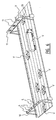
- Fig. 2 is a side view of a radar beam transmitted by the detection system of fig. 1,
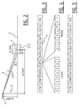
- Fig. 3 shows schematically the structure of an activating signal generated by the detection system,
- Fig. 4 shows schematically the structure of a word of the activating signal of fig. 3,
- Fig. 5 shows schematically the structure of a query signal sent to the detection system and a reply signal generated by the detection system, and
- Fig. 6 shows a perspective view of the arrangement of the detection system for use in traffic flow management.
- The invention relates to a system for detecting passing of a determined point for monitoring 1 on a
road 2, in this case a stop line at an intersection of the road and anotherroad 3, which intersection is protected with traffic lights 3 (fig. 1). This detection system comprises adevice 4 for transmitting aradar beam 5 to the point for monitoring 1, and receiving reflections of the radar radiation generated by passing vehicles V. The transmitting and receivingdevice 4, which is disposed at a location remote fromstop line 1, here on the other side of the intersection, is further adapted to determine from the received reflections that a vehicle V is passingstop line 1. The transmitting and receiving device orradar device 4 transmits at a frequency of about 24 Ghz and a power of 20 dBm (EIRP). - Only a
single traffic light 3 with associated detection system is drawn here, but it will be apparent that four such traffic lights and detection systems are installed at the intersection. - In the shown embodiment the
road 2 on which thestop line 1 is drawn has a left and right-hand lane 8L, 8R.Radar device 4 is therefore adapted to transmit tworadar beams lanes 8L, 8R. - In the shown
embodiment radar device 4 is disposed adjacently ofroad 2, andradar beams radar device 4 aboveroad 2, which often meets with practical objections. If however aportal 10 were to be placed (fig. 6), a separate radar device could be suspended above eachlane 8L, 8R, theradar beam - In order to prevent the transmitted
radar beams road 6 before they reachstop line 1,radar device 4 is placed on an elevation, here a pole 7 (fig. 2). As seen in the vertical plane,radar beams - The resulting solid angle Y between the transmitted
radar beams radar beams - The values of the different angles are given by the relations:


in which: - b is the distance between the position of
pole 7 and the point for monitoring 1 in therelevant lane 8L, 8R measured transversely of the travel direction, - d is the distance between
pole 7 and the (extension of )stop line 1 measured in the travel direction, and - h is the height of
pole 7. - In the shown embodiment the distances b and d and the height h are chosen such that the angles α, β, and γ can be set to between about 10° and 45°.
-
Radar device 4 is adapted to detectstop line 1 being passed by calculating from the received reflections the distance of the vehicle from the device and by comparing the thus calculated distance to the known distance(b 2 + d 2 + h 2) of
radar device 4 from thestop line 1. In order to prevent for instance electronic noise indevice 4 or an incident such as birds flying throughradar beams radar device 4 calculates a series of values for the distance of vehicle V from a number of successively received reflections. In the shown embodiment ten values are calculated, making use of reflections being received in each case for 10 milliseconds. A detection that a vehicle V is passingstop line 1 is then assumed to be valid only if these ten distance values correspond to each other within determined limits. In the shown embodiment the standard deviation σ of the ten distance values is calculated, and the detection is only accepted if this standard deviation is less than about half a vehicle length (σ < 2.2 m). - The detection begins when a vehicle V drives into a search field S covered by one of the radar beams 5L, 5R. The length of this search field S is entered by means of a configuration telegram to be discussed below into the control electronics of
radar device 4 prior to the first use of the detection system, and can optionally be modified during operation of the system. Search field S is defined by a lower limit SL and an upper limit SU. The values of these lower and upper limit SL, SU are chosen such that a vehicle V in therelevant radar beam 5 can be followed for some time. The maximum length of the search field, thus the distance between SL and SU, is of course determined by the horizontal and vertical distance fromradar device 4 and the vertex ofradar beam 5. With normal values of these two quantities, this length will amount to a few metres (fig. 2). - When a vehicle V passes stop
line 1, an activating signal T (fig. 3) is generated byradar device 4. This signal T, which forms part of an object telegram to be discussed below, is used to activate an external system coupled to the detection system. The activating signal can for instance be fed to a counter of a traffic control system (fig. 6) which calculates an optimum speed on the basis of the number of passing vehicles V per unit of time, and displays this speed ondisplay boards 11 above or along the road. - In order to be able to establish unambiguously the point at which a vehicle V has passed, particularly in respect of furnishing proof when the detection is used in the context of law enforcement, the object telegram transmitted by
radar device 4 also contains, in addition to activating signal T, the identification of thisradar device 4. - In the shown embodiment the detection system comprises a device 9 connected controllably to
radar device 4 for making at least one picture record of the passing vehicle. The system can thus be used as red-light camera (RLC) system. The recording device 9 can be a conventional photo camera with film roll, but in connection with capacity and speed of processing, it is recommended to make use of a digital camera. This can have its own storage medium, but can in addition or instead be connected via a communication network to a central office. - In addition to receiving activating signal T, which indicates that a vehicle V is passing
stop line 1, recording device 9 also receives in each case a signal fromtraffic light 3 when it is at red. If these two signals are provided simultaneously, this is an indication that a vehicle V is driving through red onto the intersection, and one or more picture records are made. On the basis of these picture records, in which in addition to vehicle V andred traffic light 3 all manner of additional information can be displayed, vehicle V can be identified, so that the holder of the vehicle registration can be sent a fine. - To enable optimal use of the presence of a detection system at the point being monitored thereby,
radar device 4 is further adapted in the shown embodiment to calculate the speed of the passing vehicle V from the received reflections. The detection system can thus be used not only as RLC system, but also as speed camera system. Just as in the calculation of the distance between vehicle V andradar device 4, for the speed measurement a series of values for the speed of vehicle V is also calculated from a number of successively received reflections, and the calculated speed is assumed to be valid only when the series of speed values corresponds precisely. Ten values can once again be calculated, of which the standard deviation σ must be smaller than a determined value, for instance about 5 km/h (σ ≤ 1.4 m/s), so roughly ten percent of the maximum speed usually applying at the location of traffic lights. - In order to ensure a reliable detection, it is important that only one vehicle V at a time can be detected.
Radar device 4 is therefore disposed at a distance fromstop line 1 and adapted to transmit aradar beam 5 such that the dimension ofradar beam 5 at the position ofstop line 1 is of the same order of magnitude as the width of a vehicle V. In the shown embodiment the distance betweenradar device 4 and stopline 1 is several tens of metres, while radar beams 5L, 5R each have a beam width of several degrees, more particularly 3.5° ± 1.75°. - The communication between recording device 9,
traffic light 3 andradar device 4 proceeds vialines road 2. Because red-light cameras are usually used in combination with induction loops, for communication betweenradar device 4 and recording device 9 compatibility is preferably sought with the standards developed for this purpose. The interface betweenradar device 4 and recording device 9 can thus be a 9-pin female sub D connector, the pins of which are used as follows:Connection Pin number +12 V 1 GND 3 Alarm pin A (RS485 level) 5 Alarm pin B (RS485 level) 4 RS485 (RS422) pin A-input 7 RS485 (RS422) pin B- input 6 RS485 (RS422) pin A-output 9 RS485 (RS422) pin B- output 8 Not connected 2 - The interface thus comprises the feed of the supply voltage, two RS422 outputs and an RS422 input. One of the RS422 outputs and the RS422 input serve for the data transfer. The second RS422 output, the alarm output, serves only to transmit a status or activating signal.
- This alarm output is configured as RS422 output so as to be compatible with the RS422 input on the side of recording device 9. The alarm output ultimately generates the signal which activates recording device 9 in order to make a record of a vehicle V which passes
stop line 1 whentraffic light 3 is at red. The logic levels of this signal are: - no alarm - A high, B low,
- alarm - A low, B high,
- Used for data transfer between
radar device 4 and recording device 9 are, as stated, an RS422 input and an RS422 output which operate in accordance with the specification: 19200, 8, N, 1. The data transfer takes place in the form of so-called telegrams, three types of which can be distinguished. An "object" telegram is the standard output telegram ofradar device 4 which is sent every ten milliseconds and contains data such as the distance and speed of the detected object, the signal level and status information. A "configuration" telegram is a telegram which is sent toradar device 4 for configuration thereof. In response to such a configuration telegram,radar device 4 sends a "reply" telegram. - Each telegram has a similar structure. It consists of words of in each case 16 bits, so 2 bytes, a lower byte followed by a higher byte (fig. 4). Each telegram begins with a synchronization word specifying the type of telegram. A second word indicates the length of the telegram, i.e. the number of words from the following word to the end of the telegram. There then follow words with the actual data which must be transferred, closed by a CRC-word forming the end of the telegram. This CRC-(cyclic redundancy check) word is the 16 bits sum of all values from the word indicating the number of words, so here the second word, up to and including the word immediately before the CRC-word. Remainders are not included in this sum.
- As stated, the object telegram (fig. 3) is presented every ten milliseconds, irrespective of whether there is a vehicle V in
radar beam 5. It contains data concerning the detected object and the identification forradar device 4. The total transfer time of the object telegram, which in the shown embodiment runs to nine words, amounts to 9.4 milliseconds at a transfer speed of 19200 bps. The structure of the object telegram is as follows:Word number Content 1 81h (lower byte), 75h (higher byte) 2 Length (format: integer without sign) (here 7) 3 Speed of the object in cm/s (format: integer with sign, running from -16383 to +16383) 4 Distance to the object in cm (format: integer with sign) 5 Signal amplitude of the object in dB (format: integer without sign) 6 Status 7 Identification of equipment 8 Version number of software 9 CRC - By displaying the speed in cm/s and the distance in cm a good compromise is reached between accuracy on the one hand and the measuring range on the other. The values given in the telegram for the speed and distance are otherwise not the raw momentary values, but the progressive mean over the previous 100 milliseconds (or ten detections). These values imply a prediction for the coming ten milliseconds.
- As stated, the object telegram is also presented if no object or vehicle V is to be found in
radar beam 5, and the measurement values therefore form only noise. Whether or not a vehicle V is situated inradar beam 5 is indicated bybit 0 of the lower byte of the status word, the alarm bit (1 = alarm, 0 = no alarm). This bit is activated if a vehicle V passes stopline 1 and deactivated again when vehicle V leaves search field S. The alarm status is also presented to the alarm pins of the connector. - The identification of
radar device 4 which is co-transmitted in the object telegram consists of two parts, an identification of the equipment and the identification of the software. The identification number of the equipment is stored in an EEPROM, and can only be modified or deleted by the manufacturer. Because this identification number is stored in the equipment, the software is in principle device-dependent. The identification number of the software is stored with the rest of the software in an EPROM, and can likewise only be deleted or modified by the manufacturer. - The configuration telegram serves to configure the radar device. It can be transmitted at any desired moment through the use of full-duplex RS485 (RS422) communication. As soon as
radar device 4 receives a configuration telegram, it stops transmitting object telegrams until the configuration telegram is processed and answered. The time lag between transmission of the configuration telegram and receipt of the reply telegram can amount to a full second, because the configuration data must be stored in the EEPROM, so that they also remain stored in the case of power failure. - However, when the angle correction factor - to be discussed below - is set to 0 in the configuration telegram, the configuration is not stored.
Radar device 4 then sends the existing configuration as reply. In this case nothing has to be written to the EEPROM, and the time lag between configuration telegram and reply telegram amounts to less than 1 millisecond. - After sending a receipt telegram,
radar device 4 returns once again to sending object telegrams. - The structure of the configuration telegram and the reply telegram is in principle identical. Only the lower byte of the first word, which indicates whether it is a configuration or a reply telegram, differs. The structure is as follows:
Word number Content 1 7eh, 5bh for configuration and 81h, 5bh for reply telegram 2 Length (format: integer without sign) (here 8) 3 Lower limit Vmin of search field speed in cm/s (format: integer with sign) 4 Upper limit Vmax of search field speed in cm/s (format: integer with sign) 5 Lower limit SL of search field distance in cm (format: integer with sign) 6 Upper limit SU of search field distance in cm (format: integer with sign) 7 Threshold value distance for alarm in cm 8 Control alarm function 9 Angle correction factor for distance and speed 10 CRC - The control word for the alarm function (word number 8) determines the operation of the alarm.
Bit 0, the lowest bit, indicates the direction of the alarm relative to the critical value for the distance. Ifbit 0 = 0 this means that the alarm is activated when a vehicle V approaches and the distance decreases and eventually falls below the threshold value. This is the case whenradar device 4, as seen in the travel direction, is placed beyond the point for monitoring 1 and irradiates the front side of the vehicle as shown in fig. 1 and 2. Whenbit 0 = 1 it is the case that the alarm is activated when the distance to vehicle V increases, and eventually exceeds the critical value. This is the case with aradar device 4 which, as seen in the travel direction, is placed before the point for monitoring as shown in fig. 7, and is directed at the rear side of the passing vehicles. Once the alarm is activated, it remains active in both cases until the vehicle has left the search field S. - The lower and upper limit for the speed are Vmin = 0, respectively Vmax = 5800 (58 m/s, so 209 km/h) when vehicle V is approaching radar device 4 (
bit 0 = 0), and Vmin = -5800, respectively Vmax = 0 if vehicle V is driving away from radar device 4 (bit 0 = 1). The value of ±5800 applies only when the radar device is in line with the vehicle and the angle correction factor amounts to 1 (when word number 9 has the value 1000). In the case of measurements at an angle, this value is multiplied by the angle correction factor, which amounts to 1/cosγ, wherein γ is the above discussed solid angle betweenradar beam 5 and the speed vector of vehicle V. From the above stated relation for γ it follows that the angle correction factor amounts to(b 2 + d 2 + h 2 )/d.
- The lower and upper limit for the distance amount to respectively SL = 0 and SU = 5000 (cm = 50 m) for measurements straight from the front or the rear, while the maximum distance for measurements at an angle must be divided by the angle correction factor.
- The alarm is finally activated only when two conditions are met simultaneously. In the first place the distance to the vehicle measured by
radar device 4 must exceed the threshold value, which forms an indication that the vehicle is passing the stop line. In addition, the last ten measurements, thus the measurements during the last 100 milliseconds, of both the distance and the speed of vehicle V must mutually correspond within a determined bandwidth. As already stated above, the standard deviation σ can be used as criterion herefor, wherein for instance σ ≤ 2.2 m could be used as limit values for the standard deviation in the distance measurements and σ 1.4 m/s in the speed measurements. The measurements can therefore only meet the second requirement after 100 milliseconds, which entails that the search field S must be so large that a vehicle V at a normal speed cannot drive therethrough within 100 milliseconds. - The alarm is deactivated when vehicle V leaves search field S, or when for at least one measuring cycle (of 10 milliseconds) the second requirement is not met.
- The system and the method as described above thus make it possible with simple means to establish when a vehicle passes a determined point on the road, such as a stop line, without operations on the road surface being necessary for this purpose. The method and the system are hereby highly suitable for application at busy traffic intersections. The detections are very reliable as a result of the checks applied thereto, and can also serve for law enforcement purposes.
- Although the invention has been elucidated above on the basis of a number of exemplary embodiments, it will be apparent that it is not limited thereto. Within the scope of the following claims many variants and modifications can be envisaged which are deemed to fall within the scope of this application.
Claims (26)
- Method for detecting the passage by a vehicle of a determined point for monitoring on a road, characterized in that from a remotely situated location at least one radar beam is transmitted substantially continuously to the point for monitoring, reflections from the at least one transmitted radar beam are received at the remotely situated location, and it is determined from the received reflections that the vehicle is passing the point for monitoring.
- Method as claimed in claim 1, characterized in that the at least one radar beam is transmitted at an acute angle to the travel direction of the passing vehicle.
- Method as claimed in claim 1 or 2, characterized in that passing of the point for monitoring is determined by calculating from the received reflections the distance of the vehicle from the transmitting and receiving location and comparing the thus calculated distance to the known distance between the transmitting and receiving location and the point for monitoring.
- Method as claimed in claim 3, characterized in that a series of values for the distance of the vehicle is calculated from a number of successively received reflections, and a detection that the vehicle is passing the point for monitoring is valid only if this series of distance values corresponds precisely.
- Method as claimed in any of the foregoing claims, characterized in that an activating signal is generated when a vehicle passes the point for monitoring in a determined direction.
- Method as claimed in claim 5, characterized in that an identification of the transmitting and receiving location is linked to the activating signal.
- Method as claimed in claim 5 or 6, characterized in that at least one picture record of the passing vehicle is made on the basis of the activating signal.
- Method as claimed in any of the foregoing claims, characterized in that the speed and the travel direction of the passing vehicle is also calculated from the received reflections.
- Method as claimed in claim 8, characterized in that a series of values for the speed of the vehicle is calculated from a number of successively received reflections, and a speed calculation is valid only when the series of speed values corresponds precisely.
- Method as claimed in claims 5 and 8 or 9, characterized in that the calculated speed is linked to the activating signal.
- Method as claimed in any of the foregoing claims, characterized in that the distance between the transmitting and receiving location and the point for monitoring on the one hand and the characteristic of the at least one transmitted radar beam on the other are matched such that the dimension of the radar beam at the point for monitoring is of the same order of magnitude as the width of a vehicle.
- Method as claimed in claim 11, characterized in that the distance amounts to several tens of metres and the radar beam has a beam width of several degrees.
- Method as claimed in any of the foregoing claims, characterized in that the road comprises a number of lanes, on each of which a specific point is to be monitored, and for each lane a radar beam is transmitted at a related angle from the transmitting and receiving location.
- System for detecting the passage by a vehicle of a determined point for monitoring on a road, characterized by a device disposed at a remote location for transmitting at least one radar beam substantially continuously to the point for monitoring, receiving reflections from the at least one transmitted radar beam, and determining from the received reflections that a vehicle is passing the point for monitoring.
- Detection system as claimed in claim 14, characterized in that the transmitting and receiving device is adapted to transmit the at least one radar beam at an acute angle to the travel direction of the passing vehicle.
- Detection system as claimed in claim 14 or 15, characterized in that the transmitting and receiving device is adapted to calculate from the received reflections the distance of the vehicle from the transmitting and receiving device and to compare the thus calculated distance to the known distance between the transmitting and receiving device and the point for monitoring.
- Detection system as claimed in claim 16, characterized in that the transmitting and receiving device is adapted to calculate a series of values for the distance of the vehicle from a number of successively received reflections, and to assume a detection that the vehicle is passing the point for monitoring to be valid only if the series of distance values corresponds precisely.
- Detection system as claimed in any of the claims 14-17, characterized in that the transmitting and receiving device is adapted to generate an activating signal when a vehicle passes the point for monitoring in a determined direction.
- Detection system as claimed in claim 18, characterized in that the transmitting and receiving device is adapted to link its identification to the activating signal.
- Detection system as claimed in claim 18 or 19, characterized by a device connected controllably to the transmitting and receiving device for making at least one picture record of the passing vehicle.
- Detection system as claimed in any of the claims 14-20, characterized in that the transmitting and receiving device is adapted to calculate from the received reflections the speed and the travel direction of the passing vehicle.
- Detection system as claimed in claim 21, characterized in that the transmitting and receiving device is adapted to calculate a series of values for the speed of the vehicle from a number of successively received reflections, and to assume the calculated speed to be valid only when the series of speed values corresponds precisely.
- Detection system as claimed in claims 18 and 21 or 22, characterized in that the transmitting and receiving device is adapted to link the calculated speed to the activating signal.
- Detection system as claimed in any of the claims 14-23, characterized in that the transmitting and receiving device is disposed at a distance from the point for monitoring and adapted to transmit a radar beam such that the dimension of the radar beam at the point for monitoring is of the same order of magnitude as the width of a vehicle.
- Detection system as claimed in claim 24, characterized in that the transmitting and receiving device is disposed at several tens of metres from the point for monitoring and is adapted to transmit a radar beam with a beam width of several degrees.
- Detection system as claimed in any of the claims 14-25, characterized in that the road comprises a number of lanes, on each of which a specific point is to be monitored, and the transmitting and receiving device is adapted to transmit for each lane a radar beam at a related angle.
Priority Applications (2)
| Application Number | Priority Date | Filing Date | Title |
|---|---|---|---|
| PL05077044T PL1662272T3 (en) | 2004-09-10 | 2005-09-07 | Method and system for detecting with a radar the passage of a vehicle at a point to be monitored on a road |
| HRP20190206TT HRP20190206T1 (en) | 2004-09-10 | 2019-01-31 | Method and system for detecting with a radar the passage of a vehicle at a point to be monitored on a road |
Applications Claiming Priority (1)
| Application Number | Priority Date | Filing Date | Title |
|---|---|---|---|
| NL1027018A NL1027018C2 (en) | 2004-09-10 | 2004-09-10 | Method and system for observing with radar the passing of a point to be monitored on a road through a vehicle. |
Publications (3)
| Publication Number | Publication Date |
|---|---|
| EP1662272A1 true EP1662272A1 (en) | 2006-05-31 |
| EP1662272B1 EP1662272B1 (en) | 2018-11-07 |
| EP1662272B8 EP1662272B8 (en) | 2019-01-02 |
Family
ID=34974600
Family Applications (1)
| Application Number | Title | Priority Date | Filing Date |
|---|---|---|---|
| EP05077044.5A Active EP1662272B8 (en) | 2004-09-10 | 2005-09-07 | Method and system for detecting with a radar the passage of a vehicle at a point to be monitored on a road |
Country Status (10)
| Country | Link |
|---|---|
| US (1) | US7190306B2 (en) |
| EP (1) | EP1662272B8 (en) |
| AU (1) | AU2005209646B2 (en) |
| DK (1) | DK1662272T3 (en) |
| ES (1) | ES2710318T3 (en) |
| HR (1) | HRP20190206T1 (en) |
| LT (1) | LT1662272T (en) |
| NL (1) | NL1027018C2 (en) |
| PL (1) | PL1662272T3 (en) |
| TR (1) | TR201901811T4 (en) |
Cited By (3)
| Publication number | Priority date | Publication date | Assignee | Title |
|---|---|---|---|---|
| EP2048515A1 (en) * | 2007-10-11 | 2009-04-15 | ROBOT Visual Systems GmbH | Method for determining and documenting traffic violations at a traffic light |
| WO2010097211A1 (en) | 2009-02-24 | 2010-09-02 | Gatsometer B.V. | Method and device for monitoring the state of a traffic light |
| RU2608590C2 (en) * | 2012-08-14 | 2017-01-23 | Еноптик Робот Гмбх | Method of classifying moving vehicles |
Families Citing this family (24)
| Publication number | Priority date | Publication date | Assignee | Title |
|---|---|---|---|---|
| FR2847755B1 (en) * | 2002-11-26 | 2005-04-22 | Cynove | IMAGE AUTHENTICATION METHODS |
| US7405676B2 (en) * | 2004-09-10 | 2008-07-29 | Gatsometer B.V. | Method and system for detecting with laser the passage by a vehicle of a point for monitoring on a road |
| US7541943B2 (en) * | 2006-05-05 | 2009-06-02 | Eis Electronic Integrated Systems Inc. | Traffic sensor incorporating a video camera and method of operating same |
| DE102007022373A1 (en) * | 2007-05-07 | 2008-11-13 | Robot Visual Systems Gmbh | Method for conclusively detecting the speed of a vehicle |
| EP2205990B1 (en) * | 2007-10-09 | 2012-08-29 | Adb Bvba | Device for detecting a vehicle on an airport runway |
| US8103436B1 (en) | 2007-11-26 | 2012-01-24 | Rhythm Engineering, LLC | External adaptive control systems and methods |
| KR101108708B1 (en) * | 2008-12-16 | 2012-01-30 | 한국전자통신연구원 | Sensor node had a function of calculating self position and calculating method for self position thereof |
| US20100245125A1 (en) * | 2009-03-30 | 2010-09-30 | Lasercraft, Inc. | Systems and Methods For Surveillance and Traffic Monitoring (Claim Set I) |
| US20100245568A1 (en) * | 2009-03-30 | 2010-09-30 | Lasercraft, Inc. | Systems and Methods for Surveillance and Traffic Monitoring (Claim Set II) |
| WO2012172526A1 (en) | 2011-06-17 | 2012-12-20 | Leddartech Inc. | System and method for traffic side detection and characterization |
| CN102956115A (en) * | 2011-08-31 | 2013-03-06 | 深圳富泰宏精密工业有限公司 | Traffic management device |
| USRE48914E1 (en) | 2012-03-02 | 2022-02-01 | Leddartech Inc. | System and method for multipurpose traffic detection and characterization |
| DE102013102683A1 (en) * | 2013-03-15 | 2014-09-18 | Jenoptik Robot Gmbh | Method for detecting traffic violations in a traffic light area by tailing with a radar device |
| DK2804014T3 (en) * | 2013-05-13 | 2015-08-10 | Kapsch Trafficcom Ag | DEVICES AND METHOD FOR ESTABLISHING A characteristic feature of A VEHICLE |
| DK2804013T3 (en) * | 2013-05-13 | 2015-07-06 | Kapsch Trafficcom Ag | Device for measuring the position of a vehicle or a surface thereof |
| CA2960123C (en) | 2014-09-09 | 2021-04-13 | Leddartech Inc. | Discretization of detection zone |
| US10121370B2 (en) * | 2014-09-20 | 2018-11-06 | Mohamed Roshdy Elsheemy | Comprehensive traffic control system |
| US9759812B2 (en) * | 2014-10-02 | 2017-09-12 | Trimble Inc. | System and methods for intersection positioning |
| CN108389408B (en) * | 2018-04-28 | 2020-07-03 | 山东交通学院 | Auxiliary signal control system and method for guiding vehicles in waiting area based on ground lamp panel |
| WO2021095347A1 (en) * | 2019-11-15 | 2021-05-20 | 住友電気工業株式会社 | Radio wave sensor installation method, radio wave sensor, and vehicle detection method using radio wave sensor |
| US11351999B2 (en) * | 2020-09-16 | 2022-06-07 | Xuan Binh Luu | Traffic collision warning device |
| CN112415509B (en) * | 2020-09-29 | 2022-05-03 | 成都瑞达物联科技有限公司 | Expressway pavement radar detection system and application method thereof |
| CN114220261B (en) * | 2021-11-16 | 2023-02-28 | 中国联合网络通信集团有限公司 | Vehicle speed control method and device, server and storage medium |
| CN115019557A (en) * | 2022-06-09 | 2022-09-06 | 杭州电子科技大学 | TUIO protocol-based lane virtual boundary construction and boundary crossing detection method |
Citations (8)
| Publication number | Priority date | Publication date | Assignee | Title |
|---|---|---|---|---|
| EP0335009A2 (en) * | 1988-03-26 | 1989-10-04 | Deutsche Aerospace AG | Procedure for acquiring and processing local traffic data and device for carrying out the procedure |
| EP0350751A2 (en) * | 1988-07-14 | 1990-01-17 | Multanova Ag | Method and apparatus for monitoring the speed of vehicles using a Doppler radar speed measuring device, and application of the method |
| EP0616232A2 (en) * | 1993-03-09 | 1994-09-21 | Siemens Aktiengesellschaft | Traffic radar system |
| NL9300672A (en) * | 1993-04-20 | 1994-11-16 | Gatsometer Bv | Method and apparatus for speed measurements |
| EP0636900A2 (en) * | 1993-07-30 | 1995-02-01 | Siemens Aktiengesellschaft | Method for velocity measurement and classification of vehicles by means of a traffic radar system |
| EP0730166A1 (en) * | 1995-03-03 | 1996-09-04 | Siemens Aktiengesellschaft | Method and device for measuring the traffic using a radar apparatus |
| US6232911B1 (en) * | 1994-01-12 | 2001-05-15 | O'conner Joe Scott | Device for distance measurement by radar |
| FR2835952A1 (en) | 2002-02-11 | 2003-08-15 | Electronique Controle Mesure | Detector for traffic light change to red has monitoring circuit to register successive images to determine if red light has been crossed, also using induction loop |
Family Cites Families (10)
| Publication number | Priority date | Publication date | Assignee | Title |
|---|---|---|---|---|
| US2620470A (en) * | 1946-09-13 | 1952-12-02 | Jr Roy L Rather | Doppler traffic control system |
| US2785395A (en) * | 1952-03-22 | 1957-03-12 | Leon Pearle | Speed monitor |
| US3268863A (en) * | 1964-05-01 | 1966-08-23 | Lab For Electronics Inc | Directional radar detector control |
| US5170162A (en) * | 1989-08-16 | 1992-12-08 | Whelen Technologies, Inc. | Motion direction detection |
| GB9107476D0 (en) * | 1991-04-09 | 1991-05-22 | Peek Traffic Ltd | Improvements in vehicle detection systems |
| FR2678412B1 (en) | 1991-06-28 | 1995-06-16 | Laumonier Ateliers R | METHOD FOR MONITORING, AND IF NECESSARY, AUTOMATICALLY PHOTOGRAPHING MOVING OBJECTS ON A PREDETERMINED PATH, AND DEVICE FOR CARRYING OUT SAID METHOD. |
| US5266954A (en) * | 1992-03-30 | 1993-11-30 | Microwave Sensors | Microwave vehicle detector |
| JPH07134799A (en) | 1993-11-09 | 1995-05-23 | Gakken Co Ltd | Gating vehicle management device |
| US6546119B2 (en) | 1998-02-24 | 2003-04-08 | Redflex Traffic Systems | Automated traffic violation monitoring and reporting system |
| NL1020386C2 (en) | 2002-04-15 | 2003-10-17 | Gatsometer Bv | Method and system for recording a traffic violation committed with a vehicle. |
-
2004
- 2004-09-10 NL NL1027018A patent/NL1027018C2/en active Search and Examination
-
2005
- 2005-02-18 US US11/061,304 patent/US7190306B2/en active Active
- 2005-09-07 DK DK05077044.5T patent/DK1662272T3/en active
- 2005-09-07 ES ES05077044T patent/ES2710318T3/en active Active
- 2005-09-07 LT LTEP05077044.5T patent/LT1662272T/en unknown
- 2005-09-07 TR TR2019/01811T patent/TR201901811T4/en unknown
- 2005-09-07 EP EP05077044.5A patent/EP1662272B8/en active Active
- 2005-09-07 PL PL05077044T patent/PL1662272T3/en unknown
- 2005-09-09 AU AU2005209646A patent/AU2005209646B2/en active Active
-
2019
- 2019-01-31 HR HRP20190206TT patent/HRP20190206T1/en unknown
Patent Citations (8)
| Publication number | Priority date | Publication date | Assignee | Title |
|---|---|---|---|---|
| EP0335009A2 (en) * | 1988-03-26 | 1989-10-04 | Deutsche Aerospace AG | Procedure for acquiring and processing local traffic data and device for carrying out the procedure |
| EP0350751A2 (en) * | 1988-07-14 | 1990-01-17 | Multanova Ag | Method and apparatus for monitoring the speed of vehicles using a Doppler radar speed measuring device, and application of the method |
| EP0616232A2 (en) * | 1993-03-09 | 1994-09-21 | Siemens Aktiengesellschaft | Traffic radar system |
| NL9300672A (en) * | 1993-04-20 | 1994-11-16 | Gatsometer Bv | Method and apparatus for speed measurements |
| EP0636900A2 (en) * | 1993-07-30 | 1995-02-01 | Siemens Aktiengesellschaft | Method for velocity measurement and classification of vehicles by means of a traffic radar system |
| US6232911B1 (en) * | 1994-01-12 | 2001-05-15 | O'conner Joe Scott | Device for distance measurement by radar |
| EP0730166A1 (en) * | 1995-03-03 | 1996-09-04 | Siemens Aktiengesellschaft | Method and device for measuring the traffic using a radar apparatus |
| FR2835952A1 (en) | 2002-02-11 | 2003-08-15 | Electronique Controle Mesure | Detector for traffic light change to red has monitoring circuit to register successive images to determine if red light has been crossed, also using induction loop |
Non-Patent Citations (5)
| Title |
|---|
| "GUIDANCE FOR USING RED LIGHT CAMERA", FEDERAL HIGHWAY ADMINISTRATION. NATIONAL HIGHWAY TRAFFIC SAFETY. ADMINISTRATION, 20 March 2003 (2003-03-20), pages 1 - 60, XP055135478 |
| CONTROLE AUTOMATIQUE DU TRAFFIC AUTOMOBILE PAR RADAR CATAR 2003 NOTICE TECHNIQUE 03-1971 |
| MCFADDEN J. ET AL: "SYNTHESIS AND EVALUATION OF RED LIGHT RUNNING AUTOMATED ENFORCEMENT PROGRAMS IN THE UNITED STATES", TRB, September 1999 (1999-09-01), pages 1 - 36, XP055135473 |
| MIDDLETON D. ET AL: "ADVANCES IN TRAFFIC DATA COLLECTION AND MANAGEMENT", ITS REPORT (INTELLIGENT TRANSPORTATION SYSTEMS), March 2003 (2003-03-01), pages 1 - 16, XP055135466 |
| POPOLIZIO R.E.: "NEW YORK CITY'S RED LIGHT CAMERA DEMONSTRATION PROGRAM", TRB, August 1995 (1995-08-01), pages 113 - 117, XP003033289 |
Cited By (5)
| Publication number | Priority date | Publication date | Assignee | Title |
|---|---|---|---|---|
| EP2048515A1 (en) * | 2007-10-11 | 2009-04-15 | ROBOT Visual Systems GmbH | Method for determining and documenting traffic violations at a traffic light |
| US7633433B2 (en) | 2007-10-11 | 2009-12-15 | Robot Visual Systems Gmbh | Method for detecting and documenting traffic violations at a traffic light |
| AU2008229875B2 (en) * | 2007-10-11 | 2011-06-02 | Jenoptik Robot Gmbh | Method for detecting and documenting traffic violations at a traffic light |
| WO2010097211A1 (en) | 2009-02-24 | 2010-09-02 | Gatsometer B.V. | Method and device for monitoring the state of a traffic light |
| RU2608590C2 (en) * | 2012-08-14 | 2017-01-23 | Еноптик Робот Гмбх | Method of classifying moving vehicles |
Also Published As
| Publication number | Publication date |
|---|---|
| NL1027018C2 (en) | 2006-03-13 |
| ES2710318T3 (en) | 2019-04-24 |
| AU2005209646A1 (en) | 2006-03-30 |
| EP1662272B1 (en) | 2018-11-07 |
| US20060066472A1 (en) | 2006-03-30 |
| HRP20190206T1 (en) | 2019-03-22 |
| LT1662272T (en) | 2019-02-11 |
| DK1662272T3 (en) | 2019-03-04 |
| US7190306B2 (en) | 2007-03-13 |
| TR201901811T4 (en) | 2019-03-21 |
| PL1662272T3 (en) | 2019-04-30 |
| AU2005209646B2 (en) | 2010-06-17 |
| EP1662272B8 (en) | 2019-01-02 |
Similar Documents
| Publication | Publication Date | Title |
|---|---|---|
| EP1662272B1 (en) | Method and system for detecting with a radar the passage of a vehicle at a point to be monitored on a road | |
| US7405676B2 (en) | Method and system for detecting with laser the passage by a vehicle of a point for monitoring on a road | |
| KR101291301B1 (en) | Vehicle speed measurement system using image and radar | |
| US20130201051A1 (en) | Vehicular observation and detection apparatus | |
| CN103204122A (en) | Alarm system and alarm method for vehicle lane change | |
| CN109191857A (en) | A kind of wisdom traffic management system based on big data | |
| CN111899562A (en) | Vehicle meeting prompting method for curve blind area | |
| KR20190048979A (en) | Vehicle classification system using non-contact automatic vehicle detectior | |
| US10438482B2 (en) | Method and system for remotely detecting a vehicle | |
| KR101132848B1 (en) | Monitoring system for guard rail | |
| KR101916660B1 (en) | Apparatus for vehicle sensing using radar and infrared sensor and method thereof | |
| KR102350045B1 (en) | Shaft-Operated Vehicle Monitoring System | |
| KR100906432B1 (en) | Traffic information detection system using the piezosensor and loop sensor | |
| CN208985374U (en) | Vehicle detecting system in a kind of tunnel | |
| KR101049739B1 (en) | Vehicle classifier using wheel width ratio of vehicle | |
| KR20030067298A (en) | Unmanned parking management system and method thereof | |
| CN110303983A (en) | A kind of truck turning vision dead zone method for early warning and its early warning system | |
| ITVR940042A1 (en) | VEHICLE ANTI-COLLISION SYSTEM. | |
| CN210983746U (en) | Off-site law enforcement overrun detection system | |
| KR20070100587A (en) | System for monitoring traffic accident comprising apparatus for sensing and relaying traffic accident | |
| CN209028814U (en) | Intersection safety suggestion device | |
| CN201225921Y (en) | System for preventing mine car from weighing | |
| JP2002367078A (en) | Vehicle sensing device | |
| KR20190048980A (en) | Non-contact automatic vehicle detection system | |
| JP4879788B2 (en) | Congestion judgment device and traffic judgment judgment system provided with the traffic judgment device |
Legal Events
| Date | Code | Title | Description |
|---|---|---|---|
| PUAI | Public reference made under article 153(3) epc to a published international application that has entered the european phase |
Free format text: ORIGINAL CODE: 0009012 |
|
| AK | Designated contracting states |
Kind code of ref document: A1 Designated state(s): AT BE BG CH CY CZ DE DK EE ES FI FR GB GR HU IE IS IT LI LT LU LV MC NL PL PT RO SE SI SK TR |
|
| AX | Request for extension of the european patent |
Extension state: AL BA HR MK YU |
|
| 17P | Request for examination filed |
Effective date: 20061020 |
|
| 17Q | First examination report despatched |
Effective date: 20061117 |
|
| AKX | Designation fees paid |
Designated state(s): AT BE BG CH CY CZ DE DK EE ES FI FR GB GR HU IE IS IT LI LT LU LV MC NL PL PT RO SE SI SK TR |
|
| AXX | Extension fees paid |
Extension state: YU Payment date: 20061020 Extension state: HR Payment date: 20061020 Extension state: BA Payment date: 20061020 |
|
| GRAP | Despatch of communication of intention to grant a patent |
Free format text: ORIGINAL CODE: EPIDOSNIGR1 |
|
| RIC1 | Information provided on ipc code assigned before grant |
Ipc: G01S 13/04 20060101ALI20140203BHEP Ipc: G01S 13/32 20060101ALI20140203BHEP Ipc: G01S 13/92 20060101AFI20140203BHEP Ipc: G08G 1/01 20060101ALI20140203BHEP |
|
| INTG | Intention to grant announced |
Effective date: 20140221 |
|
| GRAS | Grant fee paid |
Free format text: ORIGINAL CODE: EPIDOSNIGR3 |
|
| TPAC | Observations filed by third parties |
Free format text: ORIGINAL CODE: EPIDOSNTIPA |
|
| INTC | Intention to grant announced (deleted) | ||
| STAA | Information on the status of an ep patent application or granted ep patent |
Free format text: STATUS: GRANT OF PATENT IS INTENDED |
|
| GRAP | Despatch of communication of intention to grant a patent |
Free format text: ORIGINAL CODE: EPIDOSNIGR1 |
|
| INTG | Intention to grant announced |
Effective date: 20180517 |
|
| GRAS | Grant fee paid |
Free format text: ORIGINAL CODE: EPIDOSNIGR3 |
|
| GRAA | (expected) grant |
Free format text: ORIGINAL CODE: 0009210 |
|
| STAA | Information on the status of an ep patent application or granted ep patent |
Free format text: STATUS: THE PATENT HAS BEEN GRANTED |
|
| AK | Designated contracting states |
Kind code of ref document: B1 Designated state(s): AT BE BG CH CY CZ DE DK EE ES FI FR GB GR HU IE IS IT LI LT LU LV MC NL PL PT RO SE SI SK TR |
|
| AX | Request for extension of the european patent |
Extension state: BA HR YU |
|
| REG | Reference to a national code |
Ref country code: GB Ref legal event code: FG4D |
|
| REG | Reference to a national code |
Ref country code: AT Ref legal event code: REF Ref document number: 1062743 Country of ref document: AT Kind code of ref document: T Effective date: 20181115 Ref country code: CH Ref legal event code: NV Representative=s name: ARNOLD AND SIEDSMA AG, CH Ref country code: CH Ref legal event code: EP |
|
| REG | Reference to a national code |
Ref country code: IE Ref legal event code: FG4D |
|
| REG | Reference to a national code |
Ref country code: DE Ref legal event code: R096 Ref document number: 602005054933 Country of ref document: DE |
|
| RAP2 | Party data changed (patent owner data changed or rights of a patent transferred) |
Owner name: SENSYS GATSO NETHERLANDS B.V. |
|
| REG | Reference to a national code |
Ref country code: CH Ref legal event code: PK Free format text: BERICHTIGUNG B8 |
|
| REG | Reference to a national code |
Ref country code: HR Ref legal event code: TUEP Ref document number: P20190206 Country of ref document: HR |
|
| REG | Reference to a national code |
Ref country code: DK Ref legal event code: T3 Effective date: 20190225 |
|
| REG | Reference to a national code |
Ref country code: SE Ref legal event code: TRGR |
|
| REG | Reference to a national code |
Ref country code: NL Ref legal event code: FP |
|
| REG | Reference to a national code |
Ref country code: HR Ref legal event code: T1PR Ref document number: P20190206 Country of ref document: HR |
|
| REG | Reference to a national code |
Ref country code: AT Ref legal event code: MK05 Ref document number: 1062743 Country of ref document: AT Kind code of ref document: T Effective date: 20181107 |
|
| REG | Reference to a national code |
Ref country code: ES Ref legal event code: FG2A Ref document number: 2710318 Country of ref document: ES Kind code of ref document: T3 Effective date: 20190424 |
|
| PG25 | Lapsed in a contracting state [announced via postgrant information from national office to epo] |
Ref country code: FI Free format text: LAPSE BECAUSE OF FAILURE TO SUBMIT A TRANSLATION OF THE DESCRIPTION OR TO PAY THE FEE WITHIN THE PRESCRIBED TIME-LIMIT Effective date: 20181107 Ref country code: AT Free format text: LAPSE BECAUSE OF FAILURE TO SUBMIT A TRANSLATION OF THE DESCRIPTION OR TO PAY THE FEE WITHIN THE PRESCRIBED TIME-LIMIT Effective date: 20181107 Ref country code: IS Free format text: LAPSE BECAUSE OF FAILURE TO SUBMIT A TRANSLATION OF THE DESCRIPTION OR TO PAY THE FEE WITHIN THE PRESCRIBED TIME-LIMIT Effective date: 20190307 |
|
| PG25 | Lapsed in a contracting state [announced via postgrant information from national office to epo] |
Ref country code: PT Free format text: LAPSE BECAUSE OF FAILURE TO SUBMIT A TRANSLATION OF THE DESCRIPTION OR TO PAY THE FEE WITHIN THE PRESCRIBED TIME-LIMIT Effective date: 20190307 Ref country code: GR Free format text: LAPSE BECAUSE OF FAILURE TO SUBMIT A TRANSLATION OF THE DESCRIPTION OR TO PAY THE FEE WITHIN THE PRESCRIBED TIME-LIMIT Effective date: 20190208 |
|
| PG25 | Lapsed in a contracting state [announced via postgrant information from national office to epo] |
Ref country code: CZ Free format text: LAPSE BECAUSE OF FAILURE TO SUBMIT A TRANSLATION OF THE DESCRIPTION OR TO PAY THE FEE WITHIN THE PRESCRIBED TIME-LIMIT Effective date: 20181107 |
|
| REG | Reference to a national code |
Ref country code: SK Ref legal event code: T3 Ref document number: E 31004 Country of ref document: SK |
|
| REG | Reference to a national code |
Ref country code: DE Ref legal event code: R026 Ref document number: 602005054933 Country of ref document: DE |
|
| PLBI | Opposition filed |
Free format text: ORIGINAL CODE: 0009260 |
|
| PLAX | Notice of opposition and request to file observation + time limit sent |
Free format text: ORIGINAL CODE: EPIDOSNOBS2 |
|
| PG25 | Lapsed in a contracting state [announced via postgrant information from national office to epo] |
Ref country code: EE Free format text: LAPSE BECAUSE OF FAILURE TO SUBMIT A TRANSLATION OF THE DESCRIPTION OR TO PAY THE FEE WITHIN THE PRESCRIBED TIME-LIMIT Effective date: 20181107 Ref country code: RO Free format text: LAPSE BECAUSE OF FAILURE TO SUBMIT A TRANSLATION OF THE DESCRIPTION OR TO PAY THE FEE WITHIN THE PRESCRIBED TIME-LIMIT Effective date: 20181107 |
|
| 26 | Opposition filed |
Opponent name: IDEMIA IDENTITY & SECURITY FRANCE Effective date: 20190807 |
|
| REG | Reference to a national code |
Ref country code: HR Ref legal event code: ODRP Ref document number: P20190206 Country of ref document: HR Payment date: 20190821 Year of fee payment: 15 |
|
| PG25 | Lapsed in a contracting state [announced via postgrant information from national office to epo] |
Ref country code: SI Free format text: LAPSE BECAUSE OF FAILURE TO SUBMIT A TRANSLATION OF THE DESCRIPTION OR TO PAY THE FEE WITHIN THE PRESCRIBED TIME-LIMIT Effective date: 20181107 |
|
| PLBB | Reply of patent proprietor to notice(s) of opposition received |
Free format text: ORIGINAL CODE: EPIDOSNOBS3 |
|
| PG25 | Lapsed in a contracting state [announced via postgrant information from national office to epo] |
Ref country code: MC Free format text: LAPSE BECAUSE OF FAILURE TO SUBMIT A TRANSLATION OF THE DESCRIPTION OR TO PAY THE FEE WITHIN THE PRESCRIBED TIME-LIMIT Effective date: 20181107 |
|
| PG25 | Lapsed in a contracting state [announced via postgrant information from national office to epo] |
Ref country code: LU Free format text: LAPSE BECAUSE OF NON-PAYMENT OF DUE FEES Effective date: 20190907 |
|
| REG | Reference to a national code |
Ref country code: HR Ref legal event code: ODRP Ref document number: P20190206 Country of ref document: HR Payment date: 20200820 Year of fee payment: 16 |
|
| PG25 | Lapsed in a contracting state [announced via postgrant information from national office to epo] |
Ref country code: CY Free format text: LAPSE BECAUSE OF FAILURE TO SUBMIT A TRANSLATION OF THE DESCRIPTION OR TO PAY THE FEE WITHIN THE PRESCRIBED TIME-LIMIT Effective date: 20181107 |
|
| PG25 | Lapsed in a contracting state [announced via postgrant information from national office to epo] |
Ref country code: HU Free format text: LAPSE BECAUSE OF FAILURE TO SUBMIT A TRANSLATION OF THE DESCRIPTION OR TO PAY THE FEE WITHIN THE PRESCRIBED TIME-LIMIT; INVALID AB INITIO Effective date: 20050907 |
|
| REG | Reference to a national code |
Ref country code: HR Ref legal event code: ODRP Ref document number: P20190206 Country of ref document: HR Payment date: 20210819 Year of fee payment: 17 |
|
| RDAF | Communication despatched that patent is revoked |
Free format text: ORIGINAL CODE: EPIDOSNREV1 |
|
| APBM | Appeal reference recorded |
Free format text: ORIGINAL CODE: EPIDOSNREFNO |
|
| APBP | Date of receipt of notice of appeal recorded |
Free format text: ORIGINAL CODE: EPIDOSNNOA2O |
|
| APAH | Appeal reference modified |
Free format text: ORIGINAL CODE: EPIDOSCREFNO |
|
| REG | Reference to a national code |
Ref country code: HR Ref legal event code: ODRP Ref document number: P20190206 Country of ref document: HR Payment date: 20220906 Year of fee payment: 18 |
|
| PGFP | Annual fee paid to national office [announced via postgrant information from national office to epo] |
Ref country code: BG Payment date: 20220908 Year of fee payment: 18 |
|
| P01 | Opt-out of the competence of the unified patent court (upc) registered |
Effective date: 20230526 |
|
| REG | Reference to a national code |
Ref country code: HR Ref legal event code: ODRP Ref document number: P20190206 Country of ref document: HR Payment date: 20230821 Year of fee payment: 19 |
|
| PGFP | Annual fee paid to national office [announced via postgrant information from national office to epo] |
Ref country code: TR Payment date: 20230822 Year of fee payment: 19 Ref country code: NL Payment date: 20230926 Year of fee payment: 19 Ref country code: IT Payment date: 20230921 Year of fee payment: 19 Ref country code: IE Payment date: 20230927 Year of fee payment: 19 Ref country code: GB Payment date: 20230927 Year of fee payment: 19 |
|
| PGFP | Annual fee paid to national office [announced via postgrant information from national office to epo] |
Ref country code: SK Payment date: 20230818 Year of fee payment: 19 Ref country code: SE Payment date: 20230927 Year of fee payment: 19 Ref country code: PL Payment date: 20230821 Year of fee payment: 19 Ref country code: FR Payment date: 20230925 Year of fee payment: 19 Ref country code: DK Payment date: 20230927 Year of fee payment: 19 Ref country code: DE Payment date: 20230927 Year of fee payment: 19 Ref country code: BE Payment date: 20230927 Year of fee payment: 19 |
|
| PGFP | Annual fee paid to national office [announced via postgrant information from national office to epo] |
Ref country code: LV Payment date: 20230906 Year of fee payment: 19 Ref country code: LT Payment date: 20230821 Year of fee payment: 19 |
|
| PGFP | Annual fee paid to national office [announced via postgrant information from national office to epo] |
Ref country code: ES Payment date: 20231002 Year of fee payment: 19 |
|
| PGFP | Annual fee paid to national office [announced via postgrant information from national office to epo] |
Ref country code: CH Payment date: 20231004 Year of fee payment: 19 |