EP1662145A1 - Rotary fluid machine - Google Patents
Rotary fluid machine Download PDFInfo
- Publication number
- EP1662145A1 EP1662145A1 EP05739238A EP05739238A EP1662145A1 EP 1662145 A1 EP1662145 A1 EP 1662145A1 EP 05739238 A EP05739238 A EP 05739238A EP 05739238 A EP05739238 A EP 05739238A EP 1662145 A1 EP1662145 A1 EP 1662145A1
- Authority
- EP
- European Patent Office
- Prior art keywords
- rotation mechanism
- cylinder
- piston
- rotation
- operating parts
- Prior art date
- Legal status (The legal status is an assumption and is not a legal conclusion. Google has not performed a legal analysis and makes no representation as to the accuracy of the status listed.)
- Withdrawn
Links
Images


Classifications
-
- F—MECHANICAL ENGINEERING; LIGHTING; HEATING; WEAPONS; BLASTING
- F04—POSITIVE - DISPLACEMENT MACHINES FOR LIQUIDS; PUMPS FOR LIQUIDS OR ELASTIC FLUIDS
- F04C—ROTARY-PISTON, OR OSCILLATING-PISTON, POSITIVE-DISPLACEMENT MACHINES FOR LIQUIDS; ROTARY-PISTON, OR OSCILLATING-PISTON, POSITIVE-DISPLACEMENT PUMPS
- F04C18/00—Rotary-piston pumps specially adapted for elastic fluids
- F04C18/30—Rotary-piston pumps specially adapted for elastic fluids having the characteristics covered by two or more of groups F04C18/02, F04C18/08, F04C18/22, F04C18/24, F04C18/48, or having the characteristics covered by one of these groups together with some other type of movement between co-operating members
- F04C18/32—Rotary-piston pumps specially adapted for elastic fluids having the characteristics covered by two or more of groups F04C18/02, F04C18/08, F04C18/22, F04C18/24, F04C18/48, or having the characteristics covered by one of these groups together with some other type of movement between co-operating members having both the movement defined in group F04C18/02 and relative reciprocation between the co-operating members
-
- F—MECHANICAL ENGINEERING; LIGHTING; HEATING; WEAPONS; BLASTING
- F04—POSITIVE - DISPLACEMENT MACHINES FOR LIQUIDS; PUMPS FOR LIQUIDS OR ELASTIC FLUIDS
- F04C—ROTARY-PISTON, OR OSCILLATING-PISTON, POSITIVE-DISPLACEMENT MACHINES FOR LIQUIDS; ROTARY-PISTON, OR OSCILLATING-PISTON, POSITIVE-DISPLACEMENT PUMPS
- F04C23/00—Combinations of two or more pumps, each being of rotary-piston or oscillating-piston type, specially adapted for elastic fluids; Pumping installations specially adapted for elastic fluids; Multi-stage pumps specially adapted for elastic fluids
- F04C23/001—Combinations of two or more pumps, each being of rotary-piston or oscillating-piston type, specially adapted for elastic fluids; Pumping installations specially adapted for elastic fluids; Multi-stage pumps specially adapted for elastic fluids of similar working principle
-
- F—MECHANICAL ENGINEERING; LIGHTING; HEATING; WEAPONS; BLASTING
- F01—MACHINES OR ENGINES IN GENERAL; ENGINE PLANTS IN GENERAL; STEAM ENGINES
- F01C—ROTARY-PISTON OR OSCILLATING-PISTON MACHINES OR ENGINES
- F01C11/00—Combinations of two or more machines or engines, each being of rotary-piston or oscillating-piston type
-
- F—MECHANICAL ENGINEERING; LIGHTING; HEATING; WEAPONS; BLASTING
- F04—POSITIVE - DISPLACEMENT MACHINES FOR LIQUIDS; PUMPS FOR LIQUIDS OR ELASTIC FLUIDS
- F04C—ROTARY-PISTON, OR OSCILLATING-PISTON, POSITIVE-DISPLACEMENT MACHINES FOR LIQUIDS; ROTARY-PISTON, OR OSCILLATING-PISTON, POSITIVE-DISPLACEMENT PUMPS
- F04C18/00—Rotary-piston pumps specially adapted for elastic fluids
- F04C18/02—Rotary-piston pumps specially adapted for elastic fluids of arcuate-engagement type, i.e. with circular translatory movement of co-operating members, each member having the same number of teeth or tooth-equivalents
- F04C18/04—Rotary-piston pumps specially adapted for elastic fluids of arcuate-engagement type, i.e. with circular translatory movement of co-operating members, each member having the same number of teeth or tooth-equivalents of internal-axis type
-
- F—MECHANICAL ENGINEERING; LIGHTING; HEATING; WEAPONS; BLASTING
- F04—POSITIVE - DISPLACEMENT MACHINES FOR LIQUIDS; PUMPS FOR LIQUIDS OR ELASTIC FLUIDS
- F04C—ROTARY-PISTON, OR OSCILLATING-PISTON, POSITIVE-DISPLACEMENT MACHINES FOR LIQUIDS; ROTARY-PISTON, OR OSCILLATING-PISTON, POSITIVE-DISPLACEMENT PUMPS
- F04C23/00—Combinations of two or more pumps, each being of rotary-piston or oscillating-piston type, specially adapted for elastic fluids; Pumping installations specially adapted for elastic fluids; Multi-stage pumps specially adapted for elastic fluids
-
- F—MECHANICAL ENGINEERING; LIGHTING; HEATING; WEAPONS; BLASTING
- F04—POSITIVE - DISPLACEMENT MACHINES FOR LIQUIDS; PUMPS FOR LIQUIDS OR ELASTIC FLUIDS
- F04C—ROTARY-PISTON, OR OSCILLATING-PISTON, POSITIVE-DISPLACEMENT MACHINES FOR LIQUIDS; ROTARY-PISTON, OR OSCILLATING-PISTON, POSITIVE-DISPLACEMENT PUMPS
- F04C23/00—Combinations of two or more pumps, each being of rotary-piston or oscillating-piston type, specially adapted for elastic fluids; Pumping installations specially adapted for elastic fluids; Multi-stage pumps specially adapted for elastic fluids
- F04C23/008—Hermetic pumps
-
- F—MECHANICAL ENGINEERING; LIGHTING; HEATING; WEAPONS; BLASTING
- F04—POSITIVE - DISPLACEMENT MACHINES FOR LIQUIDS; PUMPS FOR LIQUIDS OR ELASTIC FLUIDS
- F04C—ROTARY-PISTON, OR OSCILLATING-PISTON, POSITIVE-DISPLACEMENT MACHINES FOR LIQUIDS; ROTARY-PISTON, OR OSCILLATING-PISTON, POSITIVE-DISPLACEMENT PUMPS
- F04C18/00—Rotary-piston pumps specially adapted for elastic fluids
- F04C18/02—Rotary-piston pumps specially adapted for elastic fluids of arcuate-engagement type, i.e. with circular translatory movement of co-operating members, each member having the same number of teeth or tooth-equivalents
Definitions
- the present invention relates to a rotary fluid machine, particularly to measures for controlling force exerted in the axial direction.
- Patent Publication 1 discloses a compressor having an eccentric rotation piston mechanism achieved by a cylinder having an annular cylinder chamber and an annular piston which is contained in the cylinder chamber to make eccentric rotation.
- the fluid machine compresses a refrigerant by making use of volumetric change in the cylinder chamber caused by the eccentric rotation of the piston.
- Patent Publication 1 Japanese Unexamined Patent Publication No. H6-288358
- the conventional fluid machine has only a single piston mechanism which is connected to a motor. Therefore, it has been required a component for receiving fluid pressure applied in the axial direction of a drive shaft. More specifically, the piston in the conventional fluid machine is pressed by the cylinder due to the compressed fluid pressure. As a result, a large slide loss occurs between the piston and cylinder, thereby impairing the efficiency.
- An object of the present invention is to reduce the fluid pressure in the axial direction to reduce the slide loss, thereby improving the efficiency.
- a first invention includes a first rotation mechanism (2F) and a second rotation mechanism (2S), each of which including: a cylinder (21) having an annular cylinder chamber (50); an annular piston (22) which is contained in the cylinder chamber (50) to be eccentric to the cylinder (21) and divides the cylinder chamber (50) into an outer working chamber (51) and an inner working chamber (52); and a blade (23) which is arranged in the cylinder chamber (50) to divide each of the working chambers (51, 52) into a high pressure region and a low pressure region, the piston (22) and the cylinder (21) serving as co-operating parts and any one of the piston (22) and the cylinder (21) being stationary and the other being moving such that the moving part rotates about the stationary part.
- a first rotation mechanism (2F) and a second rotation mechanism (2S each of which including: a cylinder (21) having an annular cylinder chamber (50); an annular piston (22) which is contained in the cylinder chamber (50) to be eccentric to the cylinder (21) and
- the first rotation mechanism (2F) and the second rotation mechanism (2S) are arranged to be adjacent to each other with a partition plate (2c) sandwiched therebetween and the two moving parts or the two stationary parts of the first rotation mechanism (2F) and the second rotation mechanism (2S) are arranged such that one of the co-operating parts is provided at one side of the partition plate (2c) and the other is provided at the other side of the partition plate (2c).
- the moving parts (21) of the co-operating parts rotate relative to the stationary parts (22) of the co-operating parts to change the volumes of the working chambers (51, 52).
- a fluid is compressed or expanded.
- the inner working chambers (52) of the cylinder chambers (50) of the first rotation mechanism (2F) and the second rotation mechanism ( 2S ) serve as a low-stage compression chambers and the outer working chambers (51) of the cylinder chambers (50) of the first rotation mechanism (2F) and the second rotation mechanism (2S) serve as high-stage compression chambers.
- a fluid is compressed in two stages in the first rotation mechanism (2F) and the second rotation mechanism (2S).
- the outer working chambers (51) of the cylinder chambers (50) of the first rotation mechanism (2F) and the second rotation mechanism (2S) serve as compression chambers and the inner working chambers (52) of the cylinder chambers (50) of the first rotation mechanism (2F) and the second rotation mechanism (2S) serve as expansion chambers.
- compression and expansion of a fluid are carried out in the first rotation mechanism (2F) and the second rotation mechanism (2S).
- the partition plate (2c) serves as the end plates (26) of the co-operating parts (21) of the first rotation mechanism (2F) and the second rotation mechanism (2S).
- the co-operating part (21) of the first rotation mechanism (2F) and the co-operating part (21) of the second rotation mechanism (2S) adjacent to the first rotation mechanism (2F) have individual end plates (26) and the partition plate (2c) is formed of the end plates (26) of the co-operating parts (21) of the first and second rotation mechanisms (2F, 2S).
- the moving co-operating parts (21) of the first and second rotation mechanisms (2F, 2S) are connected to a drive shaft (33) and each of the first rotation mechanism (2F) and the second rotation mechanism (2S) is provided with a compliance mechanism (60) for adjusting the position of the co-operating parts (21, 22) in the axial direction of the drive shaft (33).
- the moving co-operating parts (21) of the first and second rotation mechanisms (2F, 2S) are connected to a drive shaft (33) and each of the first rotation mechanism (2F) and the second rotation mechanism (2S) is provided with a compliance mechanism (60) for adjusting the position of the co-operating parts (21) in the direction orthogonal to the axial direction of the drive shaft (33).
- gaps that occur between the co-operating parts (21) in the radius direction are reduced to a minimum, respectively, by the compliance mechanism (60) for adjustment in the orthogonal direction.
- the moving parts (21) of the co-operating parts of the first and second rotation mechanisms (2F, 2S) are connected to a drive shaft (33) and a balance weight (75) is provided at part of the drive shaft (33) located between the end plates (26) of the co-operating parts of the first rotation mechanism (2F) and the second rotation mechanism (2S) adjacent to each other.
- the balance weight (75) eliminates imbalance caused by the rotation of the co-operating parts (21).
- the first rotation mechanism (2F) and the second rotation mechanism (2S) are configured to rotate with a 90° phase difference from each other.
- part of the annular piston (22) is cut off such that the piston (22) is C-shaped, the blade (23) extends from the inner wall surface to the outer wall surface of the cylinder chamber (50) and passes through the cut-off portion of the piston (22) and a swing bushing is provided in the cut-off portion of the piston (22) to contact the piston (22) and the blade (23) via the surfaces thereof such that the blade (23) freely reciprocates and the blade (23) and the piston (22) make relative swings.
- the blade (23) reciprocates through the swing bushing (27) and the blade (23) swings together with the swing bushing (27) relative to the piston (22). Accordingly, the cylinder (21) and the piston (22) make relative swings and rotations, whereby the rotation mechanisms (2F, 2S) achieve predetermined work such as compression.
- the working chambers (51, 52) are provided in both of the two rotation mechanisms (2F, 2S) with the end plates (26) of the co-operating parts (21) sandwiched therebetween. Therefore, fluid pressures exerted on the two co-operating parts (21) cancel out each other. Further, losses of the sliding parts caused by the rotation of the co-operating parts (21) are reduced, thereby improving the efficiency.
- the end plates (26) of the co-operating parts (21) of the first and second rotation mechanisms (2F) and (2S) are integrated. Therefore, the co-operating parts (21) are prevented from leaning (overturning). This allows smooth movement of the co-operating parts (21).
- the cylinder (21) of the first rotation mechanism (2F) and the co-operating part (21) of the second rotation mechanism (2S) are separated. Therefore, thrust losses do not occur and the co-operating parts (21) are moved separately.
- the sixth invention leakage from the ends of the co-operating parts (21, 22) is surely prevented because the axial compliance mechanism (60) is provided.
- the compliance mechanism (60) is simplified and the gaps between the ends of the co-operating parts (21, 22) are reduced.
- the compliance mechanism (60) for adjustment in the direction orthogonal to the drive shaft (33) is provided. Therefore, the co-operating parts (21) of the first and second rotation mechanisms (2F, 2S) move in the radius direction, thereby adjusting the gaps between the co-operating parts (21) in the radius direction separately. As a result, thrust losses do not occur and the gaps between the co-operating parts (21) in the radius direction are reduced.
- the balance weight (75) is used. Therefore, the imbalance caused by the rotation of the co-operating parts (21) is eliminated.
- the drive shaft (33) is prevented from flexure.
- the ninth invention since the first and second rotation mechanisms (2F, 2S) rotate with a 90° phase difference from each other, discharge occurs four times as the drive shaft (33) makes a single rotation. Therefore, the torque fluctuations are significantly reduced.
- the swing bushing (27) is provided as a connector for connecting the piston (22) and the blade (23) such that the swing bushing (27) substantially contacts the piston (22) and the blade (23) via the surfaces thereof. Therefore, the piston (22) and the blade (23) are prevented from wearing away and seizing up at the contacting parts during operation.
- the blade (23) is configured as an integral part of the cylinder (21) and supported by the cylinder (21) at both ends thereof, the blade (23) is less likely to receive abnormal concentrated load and stress concentration is less likely to occur during operation. Therefore, the sliding parts are less prone to be damaged, thereby improving the reliability of the mechanism.
- the present invention is applied to a compressor (1) as shown in FIGS. 1 to 3.
- the compressor (1) is provided in a refrigerant circuit, for example.
- the refrigerant circuit is configured to perform at least cooling or heating.
- the refrigerant circuit includes, an exterior heat exchanger serving as a heat source-side heat exchanger, an expansion valve serving as an expansion mechanism and an interior heat exchanger serving as a use-side heat exchanger which are connected in this order to the compressor (1).
- a refrigerant compressed by the compressor (1) releases heat in the exterior heat exchanger and expands at the expansion valve.
- the expanded refrigerant absorbs heat in the interior heat exchanger and returns to the compressor (1). By repeating the circulation in this manner, the room air is cooled in the interior heat exchanger.
- the compressor (1) is a completely hermetic rotary fluid machine including a compressor mechanism (20) and a motor (30) contained in a casing (10).
- the casing (10) includes a cylindrical barrel (11), a top end plate (12) fixed to the top end of the barrel (11) and a bottom end plate (13) fixed to the bottom end of the barrel (11).
- a suction pipe (14) penetrates the top end plate (12) and is connected to the interior heat exchanger.
- a discharge pipe (15) penetrates the barrel (11) and is connected to the exterior heat exchanger.
- the motor (30) is a drive mechanism and includes a stator (31) and a rotor (32).
- the stator (31) is arranged below the compressor mechanism (20) and fixed to the barrel (11) of the casing (10).
- a drive shaft (33) is connected to the rotor (32) such that the drive shaft (33) rotates together with the rotor (32).
- the drive shaft (33) has a lubrication path (not shown) extending within the drive shaft (33) in the axial direction.
- a lubrication pump (34) is provided at the bottom end of the drive shaft (33).
- the lubrication path extends upward from the lubrication pump (34) such that lubricating oil accumulated in the bottom of the casing (10) is supplied to sliding parts of the compressor mechanism (20) through the lubrication pump (34).
- the drive shaft (33) includes an eccentric part (35) at the upper part thereof.
- the eccentric part (35) is larger in diameter than the other parts of the drive shaft above and below the eccentric part (35) and deviated from the center of the drive shaft (33) by a certain amount.
- the compressor mechanism (20) is a rotation mechanism including a first rotation mechanism (2F) and a second rotation mechanism (2S).
- the compressor mechanism (20) is provided between a top housing (16) and a bottom housing (17) which are fixed to the casing (10).
- the first rotation mechanism (2F) and the second rotation mechanism (2S) are configured to be inverted upside down, their structures are the same.
- the first rotation mechanism (2F) is taken as an example.
- the first rotation mechanism (2F) includes a cylinder (21) having an annular cylinder chamber (50), an annular piston (22) which is contained in the cylinder chamber (50) and divides the cylinder chamber (50) into an outer compressor chamber (51) and an inner compressor chamber (52) and a blade (23) which divides each of the outer and inner compression chambers (51) and (52) into a high pressure region and a low pressure region as shown in FIG. 2.
- the piston (22) in the cylinder chamber (50) is configured such that eccentric rotations are made relative to the cylinder (21). Specifically, relative eccentric rotations are made by the piston (22) and the cylinder (21).
- the cylinder (21) having the cylinder chamber (50) and the piston (22) contained in the cylinder chamber (50) serve as co-operating parts and the cylinder (21) is moving and the piston (22) is stationary.
- the cylinder (21) includes an outer cylinder (24) and an inner cylinder (25).
- the outer and inner cylinders (24) and (25) are connected in one piece at the bottom by an end plate (26).
- the inner cylinder (25) is slidably fitted around the eccentric part (35) of the drive shaft (33). That is, the drive shaft (33) penetrates the cylinder chamber (50) in the vertical direction.
- the piston (22) is integrated with the top housing (16).
- the top and bottom housings (16) and (17) are provided with bearings (18) and (19) for supporting the drive shaft (33), respectively.
- the drive shaft (33) penetrates the cylinder chamber (50) in the vertical direction and parts of the drive shaft sandwiching the eccentric part (35) in the axial direction are supported by the casing (10) via the bearings (18) and (19).
- the first rotation mechanism (2F) includes a swing bushing (27) for connecting the piston (22) and the blade (23) in a movable manner.
- the piston (22) is in the form of a ring partially cut off, i.e., C-shaped.
- the blade (23) is configured to extend from the inner wall surface to the outer wall surface of the cylinder chamber (50) in the direction of the radius of the cylinder chamber (50) to pass through the cut-off portion of the piston (22) and fixed to the outer and inner cylinders (24) and (25).
- the swing bushing (27) serves as a connector for connecting the piston (22) and the blade (23) at the cut-off portion of the piston (22).
- the inner circumference surface of the outer cylinder (24) and the outer circumference surface of the inner cylinder (25) are surfaces of concentric cylinders, respectively, and a single cylinder chamber (50) is formed between them.
- the outer circumference of the piston (22) yields a smaller diameter than the diameter given by the inner circumference of the outer cylinder (24), while the inner circumference of the piston (22) yields a larger diameter than the diameter given by the outer circumference of the inner cylinder (25).
- an outer compression chamber (51) as a working chamber is formed between the outer circumference surface of the piston (22) and the inner circumference surface of the outer cylinder (24) and an inner compression chamber (52) as a working chamber is formed between the inner circumference surface of the piston (22) and the outer circumference surface of the inner cylinder (25).
- the swing bushing (27) includes a discharge-side bushing (2a) which is positioned closer to the discharge side than the blade (23) and a suction-side bushing (2b) which is positioned closer to the suction side than the blade (23).
- the discharge-side bushing (2a) and the suction-side bushing (2b) are in the same semicircle shape when viewed in section and arranged such that their flat surfaces face each other. Space between the discharge-side bushing (2a) and the suction-side bushing (2b) serves as a blade slit (28).
- the blade (23) is inserted into the blade slit (28).
- the flat surfaces of the swing bushing (27) are substantially in contact with the blade (23).
- the arc-shaped outer circumference surfaces of the swing bushing (27) are substantially in contact with the piston (22).
- the swing bushing (27) is configured such that the blade (23) inserted in the blade slit (28) reciprocates in the direction of its surface within the blade slit (28). Further, the swing bushing (27) is configured to swing together with the blade (23) relative to the piston (22). Therefore, the swing bushing (27) is configured such that the blade (23) and the piston (22) can make relative swings at the center of the swing bushing (27) and the blade (23) can reciprocate relative to the piston (22) in the direction of the surface of the blade (23).
- the discharge-side bushing (2a) and the suction-side bushing (2b) are separated.
- the bushings (2a) and (2b) may be connected at any part in one piece.
- the outer compressor chamber (51) outside the piston (22) decreases in volume in the order shown in FIGS. 3C, 3D, 3A and 3B.
- the inner compressor chamber (52) inside the piston (22) decreases in volume in the order shown in FIGS. 3A, 3B, 3C and 3D.
- the second rotation mechanism (2S) is inverted upside down from the first rotation mechanism (2F) and the piston (22) therein is integrated with the bottom housing (17). Specifically, the piston (22) of the first rotation mechanism (2F) and the piston (22) of the second rotation mechanism (2S) are inverted upside down.
- the cylinder (21) of the second rotation mechanism (2S) includes an outer cylinder (24) and an inner cylinder (25).
- the outer and inner cylinders (24) and (25) are connected in one piece at the top by an end plate (26).
- the inner cylinder (25) is slidably fitted around the eccentric part (35) of the drive shaft (33).
- the cylinder (21) of the first rotation mechanism (2F) and the cylinder (21) of the second rotation mechanism (2S) are integrated. Further, the end plate (26) of the cylinder (21) of the first rotation mechanism (2F) and the end plate (26) of the cylinder (21) of the second rotation mechanism (2S) provide a single partition plate (2c). Specifically, the partition plate ( 2c ) serves as the end plate (26) of the cylinder (21) of the first rotation mechanism (2F) and the end plate (26) of the cylinder (21) of the second rotation mechanism (2S).
- the cylinder (21) of the first rotation mechanism (2F) is provided at one of the sides of the partition plate (2c), while the cylinder (21) of the second rotation mechanism (2S) is provided at the other side of the partition plate (2c).
- a top cover plate (40) is provided on the top housing (16) and a bottom cover plate (41) is provided below the bottom housing (17).
- suction space (4a) space above the top cover plate (40)
- discharge space (4b) space below the bottom cover plate (41) is defined as discharge space (4b).
- An end of the suction pipe (14) is opened in the suction space (4a) and an end of the discharge pipe (15) is opened in the discharge space (4b).
- a first chamber (4c) and a second chamber (4d) are formed between the bottom housing (17) and the bottom cover plate (41). Further, a third chamber (4e) is formed between the top housing (16) and the top cover plate (40).
- Each of the top housing (16) and the bottom housing (17) has a vertical hole (42) which penetrates the top housing (16) or the bottom housing (17) in the axial direction.
- Each of the vertical holes (42) is elongated in shape in the radius direction.
- a pocket (4f) is formed along the outer circumference surface of the outer cylinder (24). The pocket (4f ) communicates with the suction space (4a) through the vertical hole (42) of the top housing (16) to keep the pressure in the atmosphere of the pocket (4f) at a low suction pressure.
- the pocket (4f) communicates with the first chamber (4c) through the vertical hole (42) of the bottom cover plate (41) to keep the pressure in the atmosphere of the first chamber (4c) at a low suction pressure.
- the vertical holes (42) of the top housing (16) and the bottom housing (17) are positioned at the right of the blade (23). Through the vertical holes (42) which are opened to the outer and inner compression chambers (51) and (52), the outer and inner compression chambers (51) and (52) communicate with the suction space (4a).
- the outer cylinder (24) and the piston (22) have horizontal holes (43) penetrating in the radius direction, respectively.
- the horizontal holes (43) are positioned at the right of the blade (23).
- the outer compression chamber (51) and the pocket (4f) communicate with each other through the horizontal hole (43) of the outer cylinder (24), whereby the outer compression chamber (51) communicates with the suction space (4a).
- the inner compression chamber (52) and the outer compression chamber (51) communicate with each other through the horizontal hole (43) of the piston (22), whereby the inner compression chamber (52) communicates with the suction space (4a).
- the vertical hole (42) and the horizontal holes (43) serve as suction ports for a refrigerant. Only one of the vertical hole (43) and the horizontal holes (43) may be formed as the refrigerant suction port.
- the top housing (16) has discharge ports (44) and the bottom housing (17) also has discharge ports (44).
- the discharge ports (44) penetrate the top housing (16) or the bottom housing (17) in the axial direction.
- one of the two discharge ports (44) faces the high pressure region of the outer compressor chamber (51) at one end and the other discharge port (44) faces the high pressure region of the inner compressor chamber (52) at one end.
- the discharge ports (44) are formed near the blade (23) and positioned opposite to the vertical hole (42) relative to the blade (23).
- the other ends of the discharge ports (44) communicate with the second chamber (4d) or the third chamber (4e).
- discharge valves (45) are provided as reed valves for opening/closing the discharge ports (44).
- the second chamber (4d) and the third chamber (4e) communicate with each other through a discharge path (4g) formed in the top and bottom housings (16) and (17).
- the second chamber (4d) thus communicates with the discharge space (4b).
- Seal rings (6a, 6b) are provided at the end faces of the outer cylinder (24) and the piston (22).
- the seal rings (6a) at the outer cylinder (24) are pressed toward the top housing (16) and the bottom housing (17), respectively, and the seal rings (6b) at the piston (22) are pressed toward the end plate (26) of the cylinder (21).
- the seal rings (6a, 6b) serve as a compliance mechanism (60) for adjusting the position of the cylinder (21) in the axial direction, thereby reducing the gaps that occur in the axial direction between the piston (22), cylinder (21), top housing (16) and bottom housing (17).
- the outer compressor chamber (51) forms a single chamber outside the piston (22). In this state, the volume of the outer compressor chamber (51) is substantially the maximum. Then, as the drive shaft (33) rotates to the right to change the state of the first rotation mechanism (2F) in the order shown in FIGS. 3D, 3A and 3B, the outer compressor chamber (51) decreases in volume and the refrigerant therein is compressed. When the pressure in the outer compressor chamber (51) reaches a predetermined value and the differential pressure between the outer compressor chamber (51) and the discharge space (4b) reaches a specified value, the discharge valves (45) are opened by the high pressure refrigerant in the outer compressor chamber (51). Thus, the high pressure refrigerant is released from the discharge space (4b) into the discharge pipe (15).
- the inner compressor chamber (52) suction starts when the drive shaft (33) rotates to the right from the state where the piston (22) is at the bottom dead center as shown in FIG. 3A.
- the inner compressor chamber (52) increases in volume and the refrigerant is sucked therein through the vertical hole (42) and the horizontal holes (43).
- the inner compressor chamber (51) forms a single chamber inside the piston (22). In this state, the volume of the inner compressor chamber (52) is substantially the maximum. Then, as the drive shaft (33) rotates to the right to change the state of the first rotation mechanism (2F) in the order shown in FIGS. 3B, 3C and 3D, the inner compressor chamber (52) decreases in volume and the refrigerant therein is compressed.
- the discharge valves (45) are opened by the high pressure refrigerant in the inner compressor chamber (52). Thus, the high pressure refrigerant is released from the discharge space (4b) into the discharge pipe (15).
- the high pressure refrigerant compressed in the outer compression chambers (51) and the inner compression chambers (52) of the first and second rotation mechanisms (2F) and (2S) is condensed in the exterior heat exchanger.
- the condensed refrigerant expands at the expansion valve and evaporates in the interior heat exchanger. Then, the low pressure refrigerant returns to the outer compression chambers (51) and the inner compression chambers (52). The circulation occurs in this manner.
- the outer and inner compression chambers (51) and (52) are provided at both sides of the end plate (26) located between the two cylinders (21). Therefore, the refrigerant pressures exerted on the two cylinders (21) are eliminated. Thus, losses of the sliding parts due to the rotation of the cylinders (21) are reduced, thereby improving the efficiency.
- the cylinder (21) is prevented from leaning (overturning). This allows smooth movement of the cylinders (21).
- the axial compliance mechanism (60) is provided.
- the compliance mechanism (60) is simplified and the gaps between the ends of the cylinders (21) and the ends of the pistons (22) are reduced.
- the swing bushing (27) is provided as a connector for connecting the piston (22) and the blade (23) such that the swing bushing (27) substantially contacts the piston (22) and the blade (23) via the surfaces thereof. Therefore, the piston (22) and the blade (23) are prevented from wearing away and seizing up at the contacting parts during operation.
- the blade (23) is configured as an integral part of the cylinder (21) and supported by the cylinder (21) at both ends thereof, the blade (23) is less likely to receive abnormal concentrated load and stress concentration is less likely to occur during operation. Therefore, the sliding parts are less prone to be damaged, thereby improving the reliability of the mechanism.
- the top housing (16) of the present embodiment is configured to be movable in the axial direction and space below the bottom cover plate (41) is used as the suction space (4a) as shown in FIG. 4.
- the top housing (16) is provided in the casing (10) to be movable in the axial (vertical) direction.
- the top housing (16) is fitted with pins (70) provided at the periphery of the bottom housing (17) so that it moves in the axial direction along the pins (70).
- the top cover plate (40) attached to the top housing (16) has a cylindrical part (71) at the center thereof.
- the cylindrical part (71) is movably inserted into a center opening in a support plate (72).
- the support plate (72) is disc-shaped and attached to the casing (10) at the periphery thereof.
- a compliance mechanism (60) for the axial direction is provided.
- a seal ring (73) is fitted around the cylindrical part (71) of the top cover plate (40) for sealing between the cylindrical part (71) and the support plate (72).
- a suction pipe (14) is connected to the barrel (11) of the casing (10) and a discharge pipe (15) is connected to the end plate (12). Space below the bottom cover plate (41) serves as the suction space (4a) and space above the support plate (72) serves as the discharge space (4b).
- the first chamber (4c) according to the first embodiment is omitted and the pocket (4f) between the top and bottom cover plates (40) and (41) communicates with the suction space (4a) through the vertical hole (42) formed in the bottom cover plate (41).
- the top opening of the vertical hole (42) in the top cover plate (40) is closed.
- the third chamber (4e) between the top cover plate (40) and the top housing (16) communicates with the discharge space (4b) through the cylindrical part (71), while the second chamber (4d) between the bottom cover plate (41) and the bottom housing (17) communicates with the third chamber (4e) through the discharge path (4g) formed in the drive shaft (33).
- the discharge path (4g) according to the first embodiment is omitted and the bottom end of the drive shaft (33) is supported by the casing (10) via a bearing (74). Specifically, the bearing (18) for the top housing (16) used in the first embodiment is omitted.
- a refrigerant is compressed in the outer compression chambers (51) and the inner compression chambers (52) of the first and second rotation mechanisms (2F) and (2S) on the rotation of the drive shaft (33).
- the gaps that occur in the axial direction between the piston (22), cylinder (21), top housing (16) and bottom housing (17) are adjusted to a minimum by the compliance mechanism (60).
- Other structural features and effects are the same as those of the first embodiment.
- the cylinder (21) of the first rotation mechanism (2F) includes an outer cylinder (24) and an inner cylinder (25) which are connected by an end plate (26).
- the cylinder (21) of the second rotation mechanism (2S) includes, in the same manner as the first rotation mechanism (2F), an outer cylinder (24) and an inner cylinder (25) which are connected by an end plate (26).
- One side of the end plate (26) of the cylinder (21) of the first rotation mechanism (2F) slidably contacts one side of the end plate (26) of the cylinder (21) of the second rotation mechanism (2S).
- the end plates (26) of the first and second rotation mechanisms (2F) and (2S) serve as a partition plate (2c).
- a seal ring (6c) is provided between the end plates (26).
- the seal ring (6c) serves as a compliance mechanism (60) for the axial direction and the radius direction orthogonal to the axial direction.
- the gaps between the cylinders (21) in the radius direction are individually adjusted to a minimum.
- thrust losses do not occur, thereby reducing the gaps between the cylinders (21) in the radius direction.
- space between the end plates (26) of the first and second rotation mechanisms (2F) and (2S) are set to a low suction pressure or an intermediate pressure between the low suction pressure and the high discharge pressure.
- a balance weight (75) is provided in the present embodiment as shown in FIG. 6.
- the balance weight (75) is attached to the eccentric part (35) of the drive shaft (33).
- the balance weight (75) protrudes in the direction opposite to the protrusion of the eccentric part (35) and located between the end plate (26) of the cylinder (21) of the first rotation mechanism (2F) and the end plate (26) of the cylinder (21) of the second rotation mechanism (2S). Between the end plates (26) of the first and second rotation mechanisms (2F) and (2S), space is provided at the end of the balance weight (75) opposite to the direction of protrusion of the balance weight (75).
- balance weight (75) is thus provided, imbalance due to the eccentric rotation of the cylinders (21) is eliminated.
- a seal ring (6b) serving as a compliance mechanism (60) is provided at the end of the piston (22).
- the pressure between the end plates (26) of the first and second rotation mechanisms (2F) and (2S) are set to a low suction pressure or an intermediate pressure between the low pressure and a high discharge pressure. As a result, the refrigerant pressures exerted on the two cylinders (21) cancel out each other.
- the cylinder (21) may be a stationary part and the piston (22) may be a moving part.
- the piston (22) of the first rotation mechanism (2F) and the piston (22) of the second rotation mechanism (2S) are provided at the sides of the partition plate (2c), respectively.
- the piston (22) and the cylinder (21) of the first rotation mechanism (2F) may be a stationary part and a moving part, respectively
- the cylinder (21) and the piston (22) of the second rotation mechanism (2S) may be a stationary part and a moving part, respectively.
- the moving parts of the first and second rotation mechanisms (2F) and (2S) may be eccentric in the opposite direction to each other.
- the first rotation mechanism (2F) and the second rotation mechanism (2S) may rotate with a 180° phase difference from each other. In this case, torque fluctuations due to volumetric difference between the outer and inner compression chambers (51) and (52) are reduced.
- the moving parts of the first and second rotation mechanisms (2F) and (2S) may be eccentric in different directions with an angle of 90°.
- the first rotation mechanism (2F) and the second rotation mechanism (2S) may rotate with a 90° phase difference from each other.
- FIG. 7 graph A indicates torque fluctuations that occurred when only the first rotation mechanism (2F) is provided and the outer compression chamber (51) only is formed therein. In this case, the torque varies significantly while the suction and discharge are carried out.
- Graph B in FIG. 7 indicates torque fluctuations that occurred when the first and second rotation mechanisms (2F) and (2S) are provided, only the outer compression chambers (51) are formed therein, respectively, and the first and second rotation mechanisms (2F) and (2S) rotate with a 180° phase difference from each other. In this case, discharge occurs twice as the drive shaft (33) makes a single rotation. Therefore, the torque fluctuations are reduced as compared with the case of graph A.
- Graph C in FIG. 7 indicates torque fluctuations that occurred when only the first rotation mechanism (2F) is provided and the outer and inner compression chambers (51) and (52) are formed therein.
- discharge occurs twice as the drive shaft (33) makes a single rotation. Therefore, the torque fluctuations are reduced as compared with the case of graph A.
- Graph D in FIG. 7 indicates torque fluctuations that occurred when the first and second rotation mechanisms (2F) and (2S) are provided, the outer and inner compression chambers (51) and (52) are formed in both of them, and the first and second rotation mechanisms (2F) and (2S) rotate with a 90° phase difference from each other.
- the outer and inner compression chambers (51) and (52) of the first rotation mechanism (2F) have a 180° phase difference from each other
- the outer and inner compression chambers (51) and (52) of the second rotation mechanism (2S) also have a 180° phase difference from each other.
- discharge occurs four times as the drive shaft (33) makes a single rotation. Therefore, the torque fluctuations are significantly reduced as compared with the case of graph A.
- Graph E in FIG. 7 indicates torque fluctuations that occurred when the first and second rotation mechanisms (2F) and (2S) are provided, the outer and inner compression chambers (51) and (52) are formed in both of them and the first and second rotation mechanisms (2F) and (2S) rotate with a 90° phase difference from each other. In addition, the positions of the vertical holes (43) serving as the suction ports are adjusted. In this case, the torque fluctuations are further reduced as compared with the case of graph D.
- the refrigerant may be compressed in two stages. Specifically, the refrigerant is first guided into the inner compression chambers (52) of the first and second rotation mechanisms (2F) and (2S) for the first compression. At this time, the inner compression chambers (52) serve as the low-stage compression chambers. Then, the compressed refrigerant is guided to the outer compression chambers (51) of the first and second rotation mechanisms (2F) and (2S) for the second compression, and then discharged. That is, the outer compression chambers (51) are the high-stage compression chambers. In this manner, the two-stage compression may be carried out.
- the refrigerant may be subjected to compression and expansion.
- the refrigerant is guided into the outer working chambers of the first and second rotation mechanisms (2F) and (2S) for compression.
- the outer working chambers serve as the compression chambers.
- the compressed refrigerant is cooled and guided into the inner working chambers of the first and second rotation mechanisms (2F) and (2S) for expansion.
- the inner working chambers serve as the expansion chambers.
- the expanded refrigerant is evaporated and then guided into the outer working chambers of the first and second rotation mechanisms (2F) and (2S).
- the present invention is useful as a rotary fluid machine including two working chambers in a cylinder chamber.
- the present invention is suitable for a rotary fluid machine including two rotation mechanisms.
Landscapes
- Engineering & Computer Science (AREA)
- Mechanical Engineering (AREA)
- General Engineering & Computer Science (AREA)
- Applications Or Details Of Rotary Compressors (AREA)
Abstract

Description
- The present invention relates to a rotary fluid machine, particularly to measures for controlling force exerted in the axial direction.
- As a conventional example of a fluid machine,
Patent Publication 1 discloses a compressor having an eccentric rotation piston mechanism achieved by a cylinder having an annular cylinder chamber and an annular piston which is contained in the cylinder chamber to make eccentric rotation. The fluid machine compresses a refrigerant by making use of volumetric change in the cylinder chamber caused by the eccentric rotation of the piston.
Patent Publication 1: Japanese Unexamined Patent Publication No. H6-288358 - The conventional fluid machine has only a single piston mechanism which is connected to a motor. Therefore, it has been required a component for receiving fluid pressure applied in the axial direction of a drive shaft. More specifically, the piston in the conventional fluid machine is pressed by the cylinder due to the compressed fluid pressure. As a result, a large slide loss occurs between the piston and cylinder, thereby impairing the efficiency.
- In light of the above, the present invention has been achieved. An object of the present invention is to reduce the fluid pressure in the axial direction to reduce the slide loss, thereby improving the efficiency.
- As shown in FIG. 1, a first invention includes a first rotation mechanism (2F) and a second rotation mechanism (2S), each of which including: a cylinder (21) having an annular cylinder chamber (50); an annular piston (22) which is contained in the cylinder chamber (50) to be eccentric to the cylinder (21) and divides the cylinder chamber (50) into an outer working chamber (51) and an inner working chamber (52); and a blade (23) which is arranged in the cylinder chamber (50) to divide each of the working chambers (51, 52) into a high pressure region and a low pressure region, the piston (22) and the cylinder (21) serving as co-operating parts and any one of the piston (22) and the cylinder (21) being stationary and the other being moving such that the moving part rotates about the stationary part. The first rotation mechanism (2F) and the second rotation mechanism (2S) are arranged to be adjacent to each other with a partition plate (2c) sandwiched therebetween and the two moving parts or the two stationary parts of the first rotation mechanism (2F) and the second rotation mechanism (2S) are arranged such that one of the co-operating parts is provided at one side of the partition plate (2c) and the other is provided at the other side of the partition plate (2c).
- According to the first invention, when the first and second rotation mechanisms (2F) and (2S) are actuated, the moving parts (21) of the co-operating parts rotate relative to the stationary parts (22) of the co-operating parts to change the volumes of the working chambers (51, 52). Thus, a fluid is compressed or expanded.
- According to a second invention related to the first invention, the inner working chambers (52) of the cylinder chambers (50) of the first rotation mechanism (2F) and the second rotation mechanism (2S) serve as a low-stage compression chambers and the outer working chambers (51) of the cylinder chambers (50) of the first rotation mechanism (2F) and the second rotation mechanism (2S) serve as high-stage compression chambers.
- According to the second invention, a fluid is compressed in two stages in the first rotation mechanism (2F) and the second rotation mechanism (2S).
- According to a third invention related to the first invention, the outer working chambers (51) of the cylinder chambers (50) of the first rotation mechanism (2F) and the second rotation mechanism (2S) serve as compression chambers and the inner working chambers (52) of the cylinder chambers (50) of the first rotation mechanism (2F) and the second rotation mechanism (2S) serve as expansion chambers.
- According to the third invention, compression and expansion of a fluid are carried out in the first rotation mechanism (2F) and the second rotation mechanism (2S).
- According to a fourth invention related to the first invention, the partition plate (2c) serves as the end plates (26) of the co-operating parts (21) of the first rotation mechanism (2F) and the second rotation mechanism (2S).
- According to a fifth invention related to the first invention, the co-operating part (21) of the first rotation mechanism (2F) and the co-operating part (21) of the second rotation mechanism (2S) adjacent to the first rotation mechanism (2F) have individual end plates (26) and the partition plate (2c) is formed of the end plates (26) of the co-operating parts (21) of the first and second rotation mechanisms (2F, 2S).
- According to a sixth invention related to the first invention, the moving co-operating parts (21) of the first and second rotation mechanisms (2F, 2S) are connected to a drive shaft (33) and each of the first rotation mechanism (2F) and the second rotation mechanism (2S) is provided with a compliance mechanism (60) for adjusting the position of the co-operating parts (21, 22) in the axial direction of the drive shaft (33).
- In the sixth invention, leakage from the ends of the co-operating parts (21) is prevented by the axial compliance mechanism (60).
- According to a seventh invention related to the first invention, the moving co-operating parts (21) of the first and second rotation mechanisms (2F, 2S) are connected to a drive shaft (33) and each of the first rotation mechanism (2F) and the second rotation mechanism (2S) is provided with a compliance mechanism (60) for adjusting the position of the co-operating parts (21) in the direction orthogonal to the axial direction of the drive shaft (33).
- In the seventh invention, gaps that occur between the co-operating parts (21) in the radius direction are reduced to a minimum, respectively, by the compliance mechanism (60) for adjustment in the orthogonal direction.
- According to an eighth invention related to the first invention, the moving parts (21) of the co-operating parts of the first and second rotation mechanisms (2F, 2S) are connected to a drive shaft (33) and a balance weight (75) is provided at part of the drive shaft (33) located between the end plates (26) of the co-operating parts of the first rotation mechanism (2F) and the second rotation mechanism (2S) adjacent to each other.
- In the eighth invention, the balance weight (75) eliminates imbalance caused by the rotation of the co-operating parts (21).
- According to a ninth invention related to the first invention, the first rotation mechanism (2F) and the second rotation mechanism (2S) are configured to rotate with a 90° phase difference from each other.
- In the ninth invention, discharge occurs four times while the drive shaft (33) makes a single rotation. Therefore, torque fluctuations are reduced.
- According to a tenth invention related to the first invention, in each of the first and second rotation mechanisms (2F, 2S), part of the annular piston (22) is cut off such that the piston (22) is C-shaped, the blade (23) extends from the inner wall surface to the outer wall surface of the cylinder chamber (50) and passes through the cut-off portion of the piston (22) and a swing bushing is provided in the cut-off portion of the piston (22) to contact the piston (22) and the blade (23) via the surfaces thereof such that the blade (23) freely reciprocates and the blade (23) and the piston (22) make relative swings.
- In the tenth invention, the blade (23) reciprocates through the swing bushing (27) and the blade (23) swings together with the swing bushing (27) relative to the piston (22). Accordingly, the cylinder (21) and the piston (22) make relative swings and rotations, whereby the rotation mechanisms (2F, 2S) achieve predetermined work such as compression.
- Thus, according to the present invention, the working chambers (51, 52) are provided in both of the two rotation mechanisms (2F, 2S) with the end plates (26) of the co-operating parts (21) sandwiched therebetween. Therefore, fluid pressures exerted on the two co-operating parts (21) cancel out each other. Further, losses of the sliding parts caused by the rotation of the co-operating parts (21) are reduced, thereby improving the efficiency.
- According to the fourth invention, the end plates (26) of the co-operating parts (21) of the first and second rotation mechanisms (2F) and (2S) are integrated. Therefore, the co-operating parts (21) are prevented from leaning (overturning). This allows smooth movement of the co-operating parts (21).
- According to the fifth invention, the cylinder (21) of the first rotation mechanism (2F) and the co-operating part (21) of the second rotation mechanism (2S) are separated. Therefore, thrust losses do not occur and the co-operating parts (21) are moved separately.
- According to the sixth invention, leakage from the ends of the co-operating parts (21, 22) is surely prevented because the axial compliance mechanism (60) is provided. In particular, as the two rotation mechanisms (2F, 2S) are provided, the compliance mechanism (60) is simplified and the gaps between the ends of the co-operating parts (21, 22) are reduced.
- According to the seventh invention, the compliance mechanism (60) for adjustment in the direction orthogonal to the drive shaft (33) is provided. Therefore, the co-operating parts (21) of the first and second rotation mechanisms (2F, 2S) move in the radius direction, thereby adjusting the gaps between the co-operating parts (21) in the radius direction separately. As a result, thrust losses do not occur and the gaps between the co-operating parts (21) in the radius direction are reduced.
- According to the eighth invention, the balance weight (75) is used. Therefore, the imbalance caused by the rotation of the co-operating parts (21) is eliminated.
- Further, since the balance weight (75) is provided between the first and second rotation mechanisms (2F, 2S), the drive shaft (33) is prevented from flexure.
- According to the ninth invention, since the first and second rotation mechanisms (2F, 2S) rotate with a 90° phase difference from each other, discharge occurs four times as the drive shaft (33) makes a single rotation. Therefore, the torque fluctuations are significantly reduced.
- According to the tenth invention, the swing bushing (27) is provided as a connector for connecting the piston (22) and the blade (23) such that the swing bushing (27) substantially contacts the piston (22) and the blade (23) via the surfaces thereof. Therefore, the piston (22) and the blade (23) are prevented from wearing away and seizing up at the contacting parts during operation.
- Moreover, as the blade (23) is configured as an integral part of the cylinder (21) and supported by the cylinder (21) at both ends thereof, the blade (23) is less likely to receive abnormal concentrated load and stress concentration is less likely to occur during operation. Therefore, the sliding parts are less prone to be damaged, thereby improving the reliability of the mechanism.
-
- FIG.1 is a vertical cross section of a compressor according to a first embodiment of the present invention.
- FIG. 2 is a horizontal cross section of a compressor mechanism.
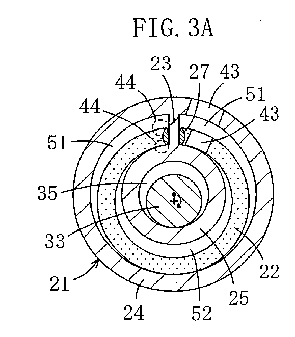
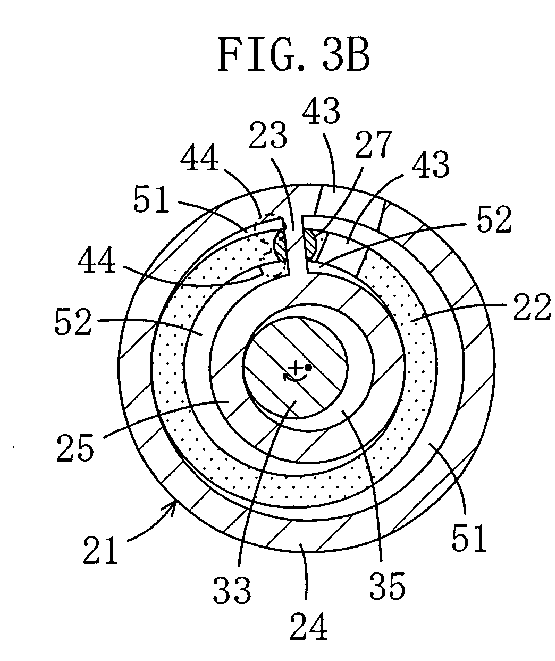
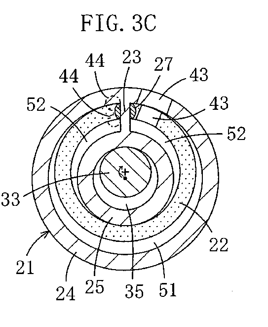
- FIGS. 3A to 3D are horizontal cross sections illustrating how the compressor mechanism works.
- FIG. 4 is a vertical cross section of a compressor according to a second embodiment of the present invention.
- FIG. 5 is a vertical cross section of a compressor according to a third embodiment of the present invention.
- FIG. 6 is a vertical cross section of a compressor according to a fourth embodiment of the present invention.
- FIG. 7 is a graph illustrating torque fluctuations according to other embodiments of the present invention.
-
- 1
- Compressor
- 10
- Casing
- 20
- Compressor mechanism
- 2F
- First rotation mechanism
- 2S
- Second rotation mechanism
- 21
- Cylinder
- 22
- Piston
- 23
- Blade
- 24
- Outer cylinder
- 25
- Inner cylinder
- 27
- Swing bushing
- 30
- Motor (drive mechanism)
- 33
- Drive shaft
- 50
- Cylinder chamber
- 51
- Outer compression chamber
- 52
- Inner compression chamber
- 60
- Compliance mechanism
- 71
- Pin
- 75
- Balance weight
- Hereinafter, embodiments of the present invention will be described in detail with reference to the drawings.
- In the present embodiment, the present invention is applied to a compressor (1) as shown in FIGS. 1 to 3. The compressor (1) is provided in a refrigerant circuit, for example.
- The refrigerant circuit is configured to perform at least cooling or heating. Specifically, the refrigerant circuit includes, an exterior heat exchanger serving as a heat source-side heat exchanger, an expansion valve serving as an expansion mechanism and an interior heat exchanger serving as a use-side heat exchanger which are connected in this order to the compressor (1). A refrigerant compressed by the compressor (1) releases heat in the exterior heat exchanger and expands at the expansion valve. Then, the expanded refrigerant absorbs heat in the interior heat exchanger and returns to the compressor (1). By repeating the circulation in this manner, the room air is cooled in the interior heat exchanger.
- The compressor (1) is a completely hermetic rotary fluid machine including a compressor mechanism (20) and a motor (30) contained in a casing (10).
- The casing (10) includes a cylindrical barrel (11), a top end plate (12) fixed to the top end of the barrel (11) and a bottom end plate (13) fixed to the bottom end of the barrel (11). A suction pipe (14) penetrates the top end plate (12) and is connected to the interior heat exchanger. A discharge pipe (15) penetrates the barrel (11) and is connected to the exterior heat exchanger.
- The motor (30) is a drive mechanism and includes a stator (31) and a rotor (32). The stator (31) is arranged below the compressor mechanism (20) and fixed to the barrel (11) of the casing (10). A drive shaft (33) is connected to the rotor (32) such that the drive shaft (33) rotates together with the rotor (32).
- The drive shaft (33) has a lubrication path (not shown) extending within the drive shaft (33) in the axial direction. At the bottom end of the drive shaft (33), a lubrication pump (34) is provided. The lubrication path extends upward from the lubrication pump (34) such that lubricating oil accumulated in the bottom of the casing (10) is supplied to sliding parts of the compressor mechanism (20) through the lubrication pump (34).
- The drive shaft (33) includes an eccentric part (35) at the upper part thereof. The eccentric part (35) is larger in diameter than the other parts of the drive shaft above and below the eccentric part (35) and deviated from the center of the drive shaft (33) by a certain amount.
- The compressor mechanism (20) is a rotation mechanism including a first rotation mechanism (2F) and a second rotation mechanism (2S). The compressor mechanism (20) is provided between a top housing (16) and a bottom housing (17) which are fixed to the casing (10). Although the first rotation mechanism (2F) and the second rotation mechanism (2S) are configured to be inverted upside down, their structures are the same. Thus, for explanation, the first rotation mechanism (2F) is taken as an example.
- The first rotation mechanism (2F) includes a cylinder (21) having an annular cylinder chamber (50), an annular piston (22) which is contained in the cylinder chamber (50) and divides the cylinder chamber (50) into an outer compressor chamber (51) and an inner compressor chamber (52) and a blade (23) which divides each of the outer and inner compression chambers (51) and (52) into a high pressure region and a low pressure region as shown in FIG. 2. The piston (22) in the cylinder chamber (50) is configured such that eccentric rotations are made relative to the cylinder (21). Specifically, relative eccentric rotations are made by the piston (22) and the cylinder (21). In the first embodiment, the cylinder (21) having the cylinder chamber (50) and the piston (22) contained in the cylinder chamber (50) serve as co-operating parts and the cylinder (21) is moving and the piston (22) is stationary.
- The cylinder (21) includes an outer cylinder (24) and an inner cylinder (25). The outer and inner cylinders (24) and (25) are connected in one piece at the bottom by an end plate (26). The inner cylinder (25) is slidably fitted around the eccentric part (35) of the drive shaft (33). That is, the drive shaft (33) penetrates the cylinder chamber (50) in the vertical direction.
- The piston (22) is integrated with the top housing (16). The top and bottom housings (16) and (17) are provided with bearings (18) and (19) for supporting the drive shaft (33), respectively. Thus, in the compressor (1) of the present embodiment, the drive shaft (33) penetrates the cylinder chamber (50) in the vertical direction and parts of the drive shaft sandwiching the eccentric part (35) in the axial direction are supported by the casing (10) via the bearings (18) and (19).
- The first rotation mechanism (2F) includes a swing bushing (27) for connecting the piston (22) and the blade (23) in a movable manner. The piston (22) is in the form of a ring partially cut off, i.e., C-shaped. The blade (23) is configured to extend from the inner wall surface to the outer wall surface of the cylinder chamber (50) in the direction of the radius of the cylinder chamber (50) to pass through the cut-off portion of the piston (22) and fixed to the outer and inner cylinders (24) and (25). The swing bushing (27) serves as a connector for connecting the piston (22) and the blade (23) at the cut-off portion of the piston (22).
- The inner circumference surface of the outer cylinder (24) and the outer circumference surface of the inner cylinder (25) are surfaces of concentric cylinders, respectively, and a single cylinder chamber (50) is formed between them. The outer circumference of the piston (22) yields a smaller diameter than the diameter given by the inner circumference of the outer cylinder (24), while the inner circumference of the piston (22) yields a larger diameter than the diameter given by the outer circumference of the inner cylinder (25). According to the structure, an outer compression chamber (51) as a working chamber is formed between the outer circumference surface of the piston (22) and the inner circumference surface of the outer cylinder (24) and an inner compression chamber (52) as a working chamber is formed between the inner circumference surface of the piston (22) and the outer circumference surface of the inner cylinder (25).
- When the outer circumference surface of the piston (22) and the inner circumference surface of the outer cylinder (24) are substantially in contact with each other at a certain point (there is a micron-order gap between them in a strict sense, but refrigerant leakage from the gap is negligible), the inner circumference surface of the piston (22) and the outer circumference surface of the inner cylinder (25) come into contact with each other at a point having a phase 180° different from the certain point.
- The swing bushing (27) includes a discharge-side bushing (2a) which is positioned closer to the discharge side than the blade (23) and a suction-side bushing (2b) which is positioned closer to the suction side than the blade (23). The discharge-side bushing (2a) and the suction-side bushing (2b) are in the same semicircle shape when viewed in section and arranged such that their flat surfaces face each other. Space between the discharge-side bushing (2a) and the suction-side bushing (2b) serves as a blade slit (28).
- The blade (23) is inserted into the blade slit (28). The flat surfaces of the swing bushing (27) are substantially in contact with the blade (23). The arc-shaped outer circumference surfaces of the swing bushing (27) are substantially in contact with the piston (22). The swing bushing (27) is configured such that the blade (23) inserted in the blade slit (28) reciprocates in the direction of its surface within the blade slit (28). Further, the swing bushing (27) is configured to swing together with the blade (23) relative to the piston (22). Therefore, the swing bushing (27) is configured such that the blade (23) and the piston (22) can make relative swings at the center of the swing bushing (27) and the blade (23) can reciprocate relative to the piston (22) in the direction of the surface of the blade (23).
- In the present embodiment, the discharge-side bushing (2a) and the suction-side bushing (2b) are separated. However, the bushings (2a) and (2b) may be connected at any part in one piece.
- In the above-described structure, when the drive shaft (33) rotates, the blade (23) reciprocates within the blade slit (28) and the outer cylinder (24) and the inner cylinder (25) swing at the center of the swing bushing (27). According to the swing movement, the contact point between the piston (22) and the cylinder (21) is shifted in the order shown in FIGS. 3A to 3D. At this time, the outer and inner cylinders (24) and (25) go around about the drive shaft (33) but do not spin by themselves.
- The outer compressor chamber (51) outside the piston (22) decreases in volume in the order shown in FIGS. 3C, 3D, 3A and 3B. The inner compressor chamber (52) inside the piston (22) decreases in volume in the order shown in FIGS. 3A, 3B, 3C and 3D.
- The second rotation mechanism (2S) is inverted upside down from the first rotation mechanism (2F) and the piston (22) therein is integrated with the bottom housing (17). Specifically, the piston (22) of the first rotation mechanism (2F) and the piston (22) of the second rotation mechanism (2S) are inverted upside down.
- The cylinder (21) of the second rotation mechanism (2S) includes an outer cylinder (24) and an inner cylinder (25). The outer and inner cylinders (24) and (25) are connected in one piece at the top by an end plate (26). The inner cylinder (25) is slidably fitted around the eccentric part (35) of the drive shaft (33).
- The cylinder (21) of the first rotation mechanism (2F) and the cylinder (21) of the second rotation mechanism (2S) are integrated. Further, the end plate (26) of the cylinder (21) of the first rotation mechanism (2F) and the end plate (26) of the cylinder (21) of the second rotation mechanism (2S) provide a single partition plate (2c). Specifically, the partition plate (2c) serves as the end plate (26) of the cylinder (21) of the first rotation mechanism (2F) and the end plate (26) of the cylinder (21) of the second rotation mechanism (2S). The cylinder (21) of the first rotation mechanism (2F) is provided at one of the sides of the partition plate (2c), while the cylinder (21) of the second rotation mechanism (2S) is provided at the other side of the partition plate (2c).
- A top cover plate (40) is provided on the top housing (16) and a bottom cover plate (41) is provided below the bottom housing (17). In the casing (10), space above the top cover plate (40) is defined as suction space (4a) and space below the bottom cover plate (41) is defined as discharge space (4b). An end of the suction pipe (14) is opened in the suction space (4a) and an end of the discharge pipe (15) is opened in the discharge space (4b).
- A first chamber (4c) and a second chamber (4d) are formed between the bottom housing (17) and the bottom cover plate (41). Further, a third chamber (4e) is formed between the top housing (16) and the top cover plate (40).
- Each of the top housing (16) and the bottom housing (17) has a vertical hole (42) which penetrates the top housing (16) or the bottom housing (17) in the axial direction. Each of the vertical holes (42) is elongated in shape in the radius direction. Between the top housing (16) and the bottom housing (17), a pocket (4f) is formed along the outer circumference surface of the outer cylinder (24). The pocket (4f) communicates with the suction space (4a) through the vertical hole (42) of the top housing (16) to keep the pressure in the atmosphere of the pocket (4f) at a low suction pressure. Further, the pocket (4f) communicates with the first chamber (4c) through the vertical hole (42) of the bottom cover plate (41) to keep the pressure in the atmosphere of the first chamber (4c) at a low suction pressure.
- Referring to FIG. 2, the vertical holes (42) of the top housing (16) and the bottom housing (17) are positioned at the right of the blade (23). Through the vertical holes (42) which are opened to the outer and inner compression chambers (51) and (52), the outer and inner compression chambers (51) and (52) communicate with the suction space (4a).
- The outer cylinder (24) and the piston (22) have horizontal holes (43) penetrating in the radius direction, respectively. Referring to FIG. 2, the horizontal holes (43) are positioned at the right of the blade (23). The outer compression chamber (51) and the pocket (4f) communicate with each other through the horizontal hole (43) of the outer cylinder (24), whereby the outer compression chamber (51) communicates with the suction space (4a). Further, the inner compression chamber (52) and the outer compression chamber (51) communicate with each other through the horizontal hole (43) of the piston (22), whereby the inner compression chamber (52) communicates with the suction space (4a). The vertical hole (42) and the horizontal holes (43) serve as suction ports for a refrigerant. Only one of the vertical hole (43) and the horizontal holes (43) may be formed as the refrigerant suction port.
- The top housing (16) has discharge ports (44) and the bottom housing (17) also has discharge ports (44). The discharge ports (44) penetrate the top housing (16) or the bottom housing (17) in the axial direction. In each of the top and bottom housings (16) and (17), one of the two discharge ports (44) faces the high pressure region of the outer compressor chamber (51) at one end and the other discharge port (44) faces the high pressure region of the inner compressor chamber (52) at one end. Specifically, the discharge ports (44) are formed near the blade (23) and positioned opposite to the vertical hole (42) relative to the blade (23). The other ends of the discharge ports (44) communicate with the second chamber (4d) or the third chamber (4e). At the outside ends of the discharge ports (44), discharge valves (45) are provided as reed valves for opening/closing the discharge ports (44).
- The second chamber (4d) and the third chamber (4e) communicate with each other through a discharge path (4g) formed in the top and bottom housings (16) and (17). The second chamber (4d) thus communicates with the discharge space (4b).
- Seal rings (6a, 6b) are provided at the end faces of the outer cylinder (24) and the piston (22). The seal rings (6a) at the outer cylinder (24) are pressed toward the top housing (16) and the bottom housing (17), respectively, and the seal rings (6b) at the piston (22) are pressed toward the end plate (26) of the cylinder (21). With this structure, the seal rings (6a, 6b) serve as a compliance mechanism (60) for adjusting the position of the cylinder (21) in the axial direction, thereby reducing the gaps that occur in the axial direction between the piston (22), cylinder (21), top housing (16) and bottom housing (17).
- Next, an explanation of how the compressor (1) works is provided.
- When the motor (30) is actuated, the rotation of the rotor (32) is transferred to the outer and inner cylinders (24) and (25) of the first rotation mechanism (2F) and the outer and inner cylinders (24) and (25) of the second rotation mechanism (2S) via the drive shaft (33). Then, in each of the first and second rotation mechanisms (2F) and (2S), the blade (23) reciprocates through the swing bushing (27), while the blade (23) and the swing bushing (27) swing together relative to the piston (22). As a result, the outer and inner cylinders (24) and (25) swing and rotate relative to the piston (22). The first and second rotation mechanisms (2F) and (2S) thus perform compression as required.
- Specifically, in the first rotation mechanism (2F), when the drive shaft (33) rotates to the right while the piston (22) is at the top dead center as shown in FIG. 3C, suction starts in the outer compression chamber (51). As the state of the first rotation mechanism (2F) changes in the order shown in FIGS. 3D, 3A and 3B, the outer compressor chamber (51) increases in volume and the refrigerant is sucked therein through the vertical hole (42) and the horizontal holes (43).
- When the piston (22) is at the top dead center as shown in FIG. 3C, the outer compressor chamber (51) forms a single chamber outside the piston (22). In this state, the volume of the outer compressor chamber (51) is substantially the maximum. Then, as the drive shaft (33) rotates to the right to change the state of the first rotation mechanism (2F) in the order shown in FIGS. 3D, 3A and 3B, the outer compressor chamber (51) decreases in volume and the refrigerant therein is compressed. When the pressure in the outer compressor chamber (51) reaches a predetermined value and the differential pressure between the outer compressor chamber (51) and the discharge space (4b) reaches a specified value, the discharge valves (45) are opened by the high pressure refrigerant in the outer compressor chamber (51). Thus, the high pressure refrigerant is released from the discharge space (4b) into the discharge pipe (15).
- In the inner compressor chamber (52), suction starts when the drive shaft (33) rotates to the right from the state where the piston (22) is at the bottom dead center as shown in FIG. 3A. As the state of the first rotation mechanism (2F) changes in the order shown in FIGS. 3B, 3C and 3D, the inner compressor chamber (52) increases in volume and the refrigerant is sucked therein through the vertical hole (42) and the horizontal holes (43).
- When the piston (22) is at the bottom dead center as shown in FIG. 3A, the inner compressor chamber (51) forms a single chamber inside the piston (22). In this state, the volume of the inner compressor chamber (52) is substantially the maximum. Then, as the drive shaft (33) rotates to the right to change the state of the first rotation mechanism (2F) in the order shown in FIGS. 3B, 3C and 3D, the inner compressor chamber (52) decreases in volume and the refrigerant therein is compressed. When the pressure in the inner compressor chamber (52) reaches a predetermined value and the differential pressure between the inner compressor chamber (52) and the discharge space (4b) reaches a specified value, the discharge valves (45) are opened by the high pressure refrigerant in the inner compressor chamber (52). Thus, the high pressure refrigerant is released from the discharge space (4b) into the discharge pipe (15).
- The same compression occurs also in the second rotation mechanism (2S) as in the first rotation mechanism (2F) and the high pressure refrigerant is released from the discharge space (4b) into the discharge pipe (15).
- The high pressure refrigerant compressed in the outer compression chambers (51) and the inner compression chambers (52) of the first and second rotation mechanisms (2F) and (2S) is condensed in the exterior heat exchanger. The condensed refrigerant expands at the expansion valve and evaporates in the interior heat exchanger. Then, the low pressure refrigerant returns to the outer compression chambers (51) and the inner compression chambers (52). The circulation occurs in this manner.
- During the compression in the first and second rotation mechanisms (2F) and (2S), refrigerant pressure in the axial direction is exerted. However, the refrigerant pressure exerted in the axial direction in the first rotation mechanism (2F) and the refrigerant pressure exerted in the axial direction in the second rotation mechanism (2S) cancel out each other. Specifically, the refrigerant pressure exerted in the axial direction in the first rotation mechanism (2F) presses the cylinder (21) downward, while the refrigerant pressure exerted in the axial direction in the second rotation mechanism (2S) presses the cylinder (21) upward. As a result, the refrigerant pressures exerted on the two cylinders (21) are eliminated.
- As described above, according to the first embodiment, the outer and inner compression chambers (51) and (52) are provided at both sides of the end plate (26) located between the two cylinders (21). Therefore, the refrigerant pressures exerted on the two cylinders (21) are eliminated. Thus, losses of the sliding parts due to the rotation of the cylinders (21) are reduced, thereby improving the efficiency.
- As the end plates (26) of the cylinders (21) of the first and second rotation mechanisms (2F) and (2S) are integrated, the cylinder (21) is prevented from leaning (overturning). This allows smooth movement of the cylinders (21).
- Further, leakage from the ends of the cylinder (21) and the ends of the pistons (22) is surely prevented because the axial compliance mechanism (60) is provided. In particular, as the two rotation mechanisms (2F, 2S) are provided, the compliance mechanism (60) is simplified and the gaps between the ends of the cylinders (21) and the ends of the pistons (22) are reduced.
- The swing bushing (27) is provided as a connector for connecting the piston (22) and the blade (23) such that the swing bushing (27) substantially contacts the piston (22) and the blade (23) via the surfaces thereof. Therefore, the piston (22) and the blade (23) are prevented from wearing away and seizing up at the contacting parts during operation.
- As the swing bushing (27), piston (22) and blade (23) are in contact with each other via the surfaces thereof, the contacting parts are sealed with reliability. Therefore, the leakage of the refrigerant from the outer and inner compression chambers (51) and (52) are surely prevented, thereby preventing a decrease in compression efficiency.
- Moreover, as the blade (23) is configured as an integral part of the cylinder (21) and supported by the cylinder (21) at both ends thereof, the blade (23) is less likely to receive abnormal concentrated load and stress concentration is less likely to occur during operation. Therefore, the sliding parts are less prone to be damaged, thereby improving the reliability of the mechanism.
- (Second Embodiment) Unlike the top housing (16) of the first embodiment fixed to the casing (10), the top housing (16) of the present embodiment is configured to be movable in the axial direction and space below the bottom cover plate (41) is used as the suction space (4a) as shown in FIG. 4.
- Specifically, the top housing (16) is provided in the casing (10) to be movable in the axial (vertical) direction. The top housing (16) is fitted with pins (70) provided at the periphery of the bottom housing (17) so that it moves in the axial direction along the pins (70).
- The top cover plate (40) attached to the top housing (16) has a cylindrical part (71) at the center thereof. The cylindrical part (71) is movably inserted into a center opening in a support plate (72). The support plate (72) is disc-shaped and attached to the casing (10) at the periphery thereof. With this structure, a compliance mechanism (60) for the axial direction is provided. A seal ring (73) is fitted around the cylindrical part (71) of the top cover plate (40) for sealing between the cylindrical part (71) and the support plate (72).
- A suction pipe (14) is connected to the barrel (11) of the casing (10) and a discharge pipe (15) is connected to the end plate (12). Space below the bottom cover plate (41) serves as the suction space (4a) and space above the support plate (72) serves as the discharge space (4b).
- The first chamber (4c) according to the first embodiment is omitted and the pocket (4f) between the top and bottom cover plates (40) and (41) communicates with the suction space (4a) through the vertical hole (42) formed in the bottom cover plate (41). The top opening of the vertical hole (42) in the top cover plate (40) is closed.
- The third chamber (4e) between the top cover plate (40) and the top housing (16) communicates with the discharge space (4b) through the cylindrical part (71), while the second chamber (4d) between the bottom cover plate (41) and the bottom housing (17) communicates with the third chamber (4e) through the discharge path (4g) formed in the drive shaft (33).
- The discharge path (4g) according to the first embodiment is omitted and the bottom end of the drive shaft (33) is supported by the casing (10) via a bearing (74). Specifically, the bearing (18) for the top housing (16) used in the first embodiment is omitted.
- Thus, also in the present embodiment, a refrigerant is compressed in the outer compression chambers (51) and the inner compression chambers (52) of the first and second rotation mechanisms (2F) and (2S) on the rotation of the drive shaft (33). At this time, the gaps that occur in the axial direction between the piston (22), cylinder (21), top housing (16) and bottom housing (17) are adjusted to a minimum by the compliance mechanism (60). Other structural features and effects are the same as those of the first embodiment.
- (Third Embodiment) Unlike the first embodiment in which the cylinders (21) of the first and second rotation mechanisms (2F) and (2S) are integrated, the cylinders (21) of the first and second rotation mechanisms (2F) and (2S) according to the present embodiment are separated as shown in FIG. 5.
- The cylinder (21) of the first rotation mechanism (2F) includes an outer cylinder (24) and an inner cylinder (25) which are connected by an end plate (26). The cylinder (21) of the second rotation mechanism (2S) includes, in the same manner as the first rotation mechanism (2F), an outer cylinder (24) and an inner cylinder (25) which are connected by an end plate (26). One side of the end plate (26) of the cylinder (21) of the first rotation mechanism (2F) slidably contacts one side of the end plate (26) of the cylinder (21) of the second rotation mechanism (2S).
- The end plates (26) of the first and second rotation mechanisms (2F) and (2S) serve as a partition plate (2c). A seal ring (6c) is provided between the end plates (26). The seal ring (6c) serves as a compliance mechanism (60) for the axial direction and the radius direction orthogonal to the axial direction.
- Specifically, as the cylinders (21) of the first and second rotation mechanisms (2F) and (2S) move in the radius direction, respectively, the gaps between the cylinders (21) in the radius direction are individually adjusted to a minimum. As a result, thrust losses do not occur, thereby reducing the gaps between the cylinders (21) in the radius direction. At this time, space between the end plates (26) of the first and second rotation mechanisms (2F) and (2S) are set to a low suction pressure or an intermediate pressure between the low suction pressure and the high discharge pressure.
- Since the cylinder (21) of the first rotation mechanism (2F) and the cylinder (21) of the second rotation mechanism (2S) are separated, the thrust losses do not occur and the cylinders move separately. Other structural features and effects are the same as those of the first embodiment.
- If the pressure between the end plates (26) of the first and second rotation mechanisms (2F) and (2S) are set to a high discharge pressure, the refrigerant pressures exerted on the cylinders (21) do not cancel out each other.
- In addition to the separation of the cylinders (21) of the first rotation mechanism (2F) and the second rotation mechanism (2S) according to the third embodiment, a balance weight (75) is provided in the present embodiment as shown in FIG. 6.
- Specifically, the balance weight (75) is attached to the eccentric part (35) of the drive shaft (33). The balance weight (75) protrudes in the direction opposite to the protrusion of the eccentric part (35) and located between the end plate (26) of the cylinder (21) of the first rotation mechanism (2F) and the end plate (26) of the cylinder (21) of the second rotation mechanism (2S). Between the end plates (26) of the first and second rotation mechanisms (2F) and (2S), space is provided at the end of the balance weight (75) opposite to the direction of protrusion of the balance weight (75).
- As the balance weight (75) is thus provided, imbalance due to the eccentric rotation of the cylinders (21) is eliminated.
- Since the balance weight (75) is provided between the first and second rotation mechanisms (2F) and (2S), the drive shaft (33) is prevented from flexure.
- Further, a seal ring (6b) serving as a compliance mechanism (60) is provided at the end of the piston (22). Other structural features and effects are the same as those of the third embodiment. The pressure between the end plates (26) of the first and second rotation mechanisms (2F) and (2S) are set to a low suction pressure or an intermediate pressure between the low pressure and a high discharge pressure. As a result, the refrigerant pressures exerted on the two cylinders (21) cancel out each other.
- If the pressure between the end plates (26) of the first and second rotation mechanisms (2F) and (2S) is set to a high discharge pressure, the refrigerant pressures exerted on the two cylinders (21) do not cancel out each other.
- The following variations may be added to the first embodiment of the present invention.
- According to the present invention, the cylinder (21) may be a stationary part and the piston (22) may be a moving part. In this case, the piston (22) of the first rotation mechanism (2F) and the piston (22) of the second rotation mechanism (2S) are provided at the sides of the partition plate (2c), respectively.
- According to the present invention, the piston (22) and the cylinder (21) of the first rotation mechanism (2F) may be a stationary part and a moving part, respectively, and the cylinder (21) and the piston (22) of the second rotation mechanism (2S) may be a stationary part and a moving part, respectively.
- According to the present invention, the moving parts of the first and second rotation mechanisms (2F) and (2S) may be eccentric in the opposite direction to each other. Specifically, the first rotation mechanism (2F) and the second rotation mechanism (2S) may rotate with a 180° phase difference from each other. In this case, torque fluctuations due to volumetric difference between the outer and inner compression chambers (51) and (52) are reduced.
- Alternatively, the moving parts of the first and second rotation mechanisms (2F) and (2S) may be eccentric in different directions with an angle of 90°. Specifically, the first rotation mechanism (2F) and the second rotation mechanism (2S) may rotate with a 90° phase difference from each other.
- As the moving parts of the compressor (1) are eccentric, torque fluctuations occur as shown in FIG. 7. In FIG. 7, graph A indicates torque fluctuations that occurred when only the first rotation mechanism (2F) is provided and the outer compression chamber (51) only is formed therein. In this case, the torque varies significantly while the suction and discharge are carried out.
- Graph B in FIG. 7 indicates torque fluctuations that occurred when the first and second rotation mechanisms (2F) and (2S) are provided, only the outer compression chambers (51) are formed therein, respectively, and the first and second rotation mechanisms (2F) and (2S) rotate with a 180° phase difference from each other. In this case, discharge occurs twice as the drive shaft (33) makes a single rotation. Therefore, the torque fluctuations are reduced as compared with the case of graph A.
- Graph C in FIG. 7 indicates torque fluctuations that occurred when only the first rotation mechanism (2F) is provided and the outer and inner compression chambers (51) and (52) are formed therein. In this case, as shown in FIG. 3 according to the first embodiment, discharge occurs twice as the drive shaft (33) makes a single rotation. Therefore, the torque fluctuations are reduced as compared with the case of graph A.
- Graph D in FIG. 7 indicates torque fluctuations that occurred when the first and second rotation mechanisms (2F) and (2S) are provided, the outer and inner compression chambers (51) and (52) are formed in both of them, and the first and second rotation mechanisms (2F) and (2S) rotate with a 90° phase difference from each other. In this case, the outer and inner compression chambers (51) and (52) of the first rotation mechanism (2F) have a 180° phase difference from each other, while the outer and inner compression chambers (51) and (52) of the second rotation mechanism (2S) also have a 180° phase difference from each other. In addition, as the first and second rotation mechanisms (2F) and (2S) rotate with a 90° phase difference from each other, discharge occurs four times as the drive shaft (33) makes a single rotation. Therefore, the torque fluctuations are significantly reduced as compared with the case of graph A.
- Graph E in FIG. 7 indicates torque fluctuations that occurred when the first and second rotation mechanisms (2F) and (2S) are provided, the outer and inner compression chambers (51) and (52) are formed in both of them and the first and second rotation mechanisms (2F) and (2S) rotate with a 90° phase difference from each other. In addition, the positions of the vertical holes (43) serving as the suction ports are adjusted. In this case, the torque fluctuations are further reduced as compared with the case of graph D.
- In the present invention, the refrigerant may be compressed in two stages. Specifically, the refrigerant is first guided into the inner compression chambers (52) of the first and second rotation mechanisms (2F) and (2S) for the first compression. At this time, the inner compression chambers (52) serve as the low-stage compression chambers. Then, the compressed refrigerant is guided to the outer compression chambers (51) of the first and second rotation mechanisms (2F) and (2S) for the second compression, and then discharged. That is, the outer compression chambers (51) are the high-stage compression chambers. In this manner, the two-stage compression may be carried out.
- Further, according to the present invention, the refrigerant may be subjected to compression and expansion. First, the refrigerant is guided into the outer working chambers of the first and second rotation mechanisms (2F) and (2S) for compression. At this time, the outer working chambers serve as the compression chambers. Then, the compressed refrigerant is cooled and guided into the inner working chambers of the first and second rotation mechanisms (2F) and (2S) for expansion. At this time, the inner working chambers serve as the expansion chambers. Thereafter, the expanded refrigerant is evaporated and then guided into the outer working chambers of the first and second rotation mechanisms (2F) and (2S). Thus, these steps are repeated.
- As described above, the present invention is useful as a rotary fluid machine including two working chambers in a cylinder chamber. In particular, the present invention is suitable for a rotary fluid machine including two rotation mechanisms.
Claims (10)
- A rotary fluid machine comprising a first rotation mechanism (2F) and a second rotation mechanism (2S), each of which including:a cylinder (21) having an annular cylinder chamber (50);an annular piston (22) which is contained in the cylinder chamber (50) to be eccentric to the cylinder (21) and divides the cylinder chamber (50) into an outer working chamber (51) and an inner working chamber (52); anda blade (23) which is arranged in the cylinder chamber (50) to divide each of the working chambers (51, 52) into a high pressure region and a low pressure region, the piston (22) and the cylinder (21) serving as co-operating parts and any one of the piston (22) and the cylinder (21) being stationary and the other being moving such that the moving co-operating part rotates about the stationary co-operating part, whereinthe first rotation mechanism (2F) and the second rotation mechanism (2S) are arranged to be adjacent to each other with a partition plate (2c) sandwiched therebetween andthe two moving co-operating parts (21) or the two stationary co-operating parts (22) of the first rotation mechanism (2F) and the second rotation mechanism (2S) are arranged such that one of the co-operating parts is provided at one side of the end plate (2c) and the other is provided at the other side of the end plate (2c).
- The rotary fluid machine according to claim 1, wherein
the inner working chambers (52) of the cylinder chambers (50) of the first rotation mechanism (2F) and the second rotation mechanism (2S) serve as low-stage compression chambers and
the outer working chambers (51) of the cylinder chambers (50) of the first rotation mechanism (2F) and the second rotation mechanism (2S) serve as high-stage compression chambers. - The rotary fluid machine according to claim 1, wherein
the outer working chambers (51) of the cylinder chambers (50) of the first rotation mechanism (2F) and the second rotation mechanism (2S) serve as compression chambers and
the inner working chambers (52) of the cylinder chambers (50) of the first rotation mechanism (2F) and the second rotation mechanism (2S) serve as expansion chambers. - The rotary fluid machine according to claim 1, wherein
the partition plate (2c) serves as the end plates (26) of the co-operating parts (21) of the first rotation mechanism (2F) and the second rotation mechanism (2S). - The rotary fluid machine according to claim 1, wherein
the co-operating part (21) of the first rotation mechanism (2F) and the co-operating part (21) of the second rotation mechanism (2S) adjacent to the first rotation mechanism (2F) have individual end plates (26), and
the partition plate (2c) is formed of the end plates (26) of the co-operating parts (21) of the first and second rotation mechanisms (2F, 2S). - The rotary fluid machine according to claim 1, wherein
the moving co-operating parts (21) of the first and second rotation mechanisms (2F, 2S) are connected to a drive shaft (33) and
each of the first rotation mechanism (2F) and the second rotation mechanism (2S) is provided with a compliance mechanism (60) for adjusting the position of the co-operating parts (21, 22) in the axial direction of the drive shaft (33). - The rotary fluid machine according to claim 1, wherein
the moving co-operating parts (21) of the first and second rotation mechanisms (2F, 2S) are connected to a drive shaft (33) and
each of the first rotation mechanism (2F) and the second rotation mechanism (2S) is provided with a compliance mechanism (60) for adjusting the position of the co-operating parts (21) in the direction orthogonal to the axial direction of the drive shaft (33). - The rotary fluid machine according to claim 4, wherein
the moving co-operating parts (21) of the first and second rotation mechanisms (2F, 2S) are connected to a drive shaft (33) and
a balance weight (75) is provided at part of the drive shaft (33) located between the end plates (26) of the co-operating parts of the first rotation mechanism (2F) and the second rotation mechanism (2S) adjacent to each other. - The rotary fluid machine according to claim 1, wherein
the first rotation mechanism (2F) and the second rotation mechanism (2S) are configured to rotate with a 90° phase difference from each other. - The rotary fluid machine according to claim 1, wherein
in each of the first and second rotation mechanisms (2F, 2S), part of the annular piston (22) is cut off such that the piston (22) is C-shaped,
the blade (23) extends from the inner wall surface to the outer wall surface of the cylinder chamber (50) and passes through the cut-off portion of the piston (22) and
a swing bushing is provided in the cut-off portion of the piston (22) to contact the piston (22) and the blade (23) via the surfaces thereof such that the blade (23) freely reciprocates and the blade (23) and the piston (22) make relative swings.
Applications Claiming Priority (2)
| Application Number | Priority Date | Filing Date | Title |
|---|---|---|---|
| JP2004140696A JP3757977B2 (en) | 2004-05-11 | 2004-05-11 | Rotary fluid machine |
| PCT/JP2005/008636 WO2005108795A1 (en) | 2004-05-11 | 2005-05-11 | Rotary fluid machine |
Publications (2)
| Publication Number | Publication Date |
|---|---|
| EP1662145A1 true EP1662145A1 (en) | 2006-05-31 |
| EP1662145A4 EP1662145A4 (en) | 2012-06-06 |
Family
ID=35320287
Family Applications (1)
| Application Number | Title | Priority Date | Filing Date |
|---|---|---|---|
| EP05739238A Withdrawn EP1662145A4 (en) | 2004-05-11 | 2005-05-11 | ROTARY FLUID MACHINE |
Country Status (7)
| Country | Link |
|---|---|
| US (1) | US7549851B2 (en) |
| EP (1) | EP1662145A4 (en) |
| JP (1) | JP3757977B2 (en) |
| KR (1) | KR100850847B1 (en) |
| CN (1) | CN100487250C (en) |
| AU (1) | AU2005240932B2 (en) |
| WO (1) | WO2005108795A1 (en) |
Cited By (3)
| Publication number | Priority date | Publication date | Assignee | Title |
|---|---|---|---|---|
| CN101939546A (en) * | 2008-02-04 | 2011-01-05 | 大金工业株式会社 | fluid machinery |
| EP1992820A4 (en) * | 2006-03-09 | 2014-01-08 | Daikin Ind Ltd | FREEZING DEVICE |
| EP2251546A4 (en) * | 2008-02-04 | 2015-08-19 | Daikin Ind Ltd | COMPRESSOR AND FREEZER |
Families Citing this family (15)
| Publication number | Priority date | Publication date | Assignee | Title |
|---|---|---|---|---|
| JP3874016B2 (en) * | 2005-05-23 | 2007-01-31 | ダイキン工業株式会社 | Rotary compressor |
| EP2196677A4 (en) * | 2007-09-14 | 2015-01-14 | Daikin Ind Ltd | ROTARY FLUID MACHINE |
| JP4305550B2 (en) * | 2007-09-28 | 2009-07-29 | ダイキン工業株式会社 | Rotary fluid machine |
| JP4609496B2 (en) * | 2008-01-18 | 2011-01-12 | ダイキン工業株式会社 | Rotary fluid machine |
| US8323009B2 (en) | 2008-01-24 | 2012-12-04 | Daikin Industries, Ltd. | Rotary-type fluid machine |
| JP4130470B1 (en) * | 2008-02-14 | 2008-08-06 | 株式会社大和電機商会 | Liquid transfer pump |
| JP2009222329A (en) * | 2008-03-18 | 2009-10-01 | Daikin Ind Ltd | Refrigerating device |
| JP5217818B2 (en) * | 2008-09-12 | 2013-06-19 | ダイキン工業株式会社 | Rotary compressor |
| JP5217856B2 (en) * | 2008-09-30 | 2013-06-19 | ダイキン工業株式会社 | Rotary compressor |
| JP2010084662A (en) * | 2008-09-30 | 2010-04-15 | Daikin Ind Ltd | Rotary compressor |
| JP5343501B2 (en) * | 2008-10-07 | 2013-11-13 | ダイキン工業株式会社 | Rotary compressor |
| JP5263089B2 (en) * | 2009-09-02 | 2013-08-14 | ダイキン工業株式会社 | Rotary compressor |
| WO2014156842A1 (en) * | 2013-03-28 | 2014-10-02 | 株式会社イワキ | Positive displacement pump |
| JP6324859B2 (en) * | 2014-09-26 | 2018-05-16 | 株式会社イワキ | Positive displacement pump |
| CN104533791B (en) * | 2014-11-07 | 2016-06-29 | 广东美芝制冷设备有限公司 | Compressor |
Family Cites Families (34)
| Publication number | Priority date | Publication date | Assignee | Title |
|---|---|---|---|---|
| US300628A (en) * | 1884-06-17 | Oscillating metee | ||
| US453641A (en) * | 1891-06-09 | Steam-engine | ||
| US3125031A (en) * | 1964-03-17 | Multi-chamber rotary pump | ||
| FR357884A (en) * | 1905-09-20 | 1906-01-18 | Robert Nass | Rotary steam engine |
| GB756958A (en) * | 1953-10-16 | 1956-09-12 | Bryce Stephen Butler | Improvements in or relating to rotary displacement pumps, compressors and motors |
| US2966898A (en) * | 1957-08-26 | 1961-01-03 | Jacobs Albert Joseph | Rotary piston internal combustion engine |
| US3782865A (en) * | 1971-03-05 | 1974-01-01 | A Braun | Sealing sleeve |
| JPS5123371Y1 (en) * | 1973-10-11 | 1976-06-16 | ||
| JPS5123371A (en) * | 1974-08-15 | 1976-02-24 | Meibundo Insatsu Kogyo Kk | SHIITO CHOGOKI |
| JPS58182995A (en) * | 1982-04-20 | 1983-10-26 | Matsushita Electric Ind Co Ltd | Diaphragm for speaker |
| JPS5941602A (en) * | 1982-09-01 | 1984-03-07 | Daikin Ind Ltd | Double multivane type rotary machine |
| JPS5960087A (en) * | 1982-09-30 | 1984-04-05 | Shimadzu Corp | displacement fluid machine |
| JPS59113289A (en) | 1982-12-18 | 1984-06-29 | Mitsue Tamasaki | Rotary compressor |
| JPS6090584U (en) * | 1983-11-29 | 1985-06-21 | 三菱重工業株式会社 | Ring swing type fluid machine |
| EP0188494A1 (en) * | 1984-07-12 | 1986-07-30 | Russell John Searle | Gyrating piston machine |
| JPS61151090U (en) * | 1985-03-13 | 1986-09-18 | ||
| JPS62138802U (en) * | 1986-02-27 | 1987-09-01 | ||
| JPS6360091U (en) | 1986-10-06 | 1988-04-21 | ||
| JPH0237192A (en) * | 1988-05-12 | 1990-02-07 | Sanden Corp | Scroll type fluid device |
| CA2063888C (en) | 1991-04-26 | 2001-08-07 | Hubert Richardson Jr. | Orbiting rotary compressor |
| JPH06159278A (en) * | 1992-04-01 | 1994-06-07 | Nippon Soken Inc | Rolling piston compressor |
| JP3104414B2 (en) * | 1992-07-21 | 2000-10-30 | 株式会社日立製作所 | Synchronous rotary scroll fluid machine |
| JP3689819B2 (en) * | 1994-11-02 | 2005-08-31 | 株式会社日立製作所 | Scroll compressor |
| JP3509299B2 (en) * | 1995-06-20 | 2004-03-22 | 株式会社日立製作所 | Scroll compressor |
| GR980100045A (en) * | 1998-01-30 | 1999-09-30 | Omega type pump | |
| US7290990B2 (en) * | 1998-06-05 | 2007-11-06 | Carrier Corporation | Short reverse rotation of compressor at startup |
| JP2000104677A (en) * | 1998-09-25 | 2000-04-11 | Toshiba Corp | Fluid machinery |
| DE29819360U1 (en) * | 1998-11-03 | 1999-01-14 | Kuechler, Jürgen, Dr., 35096 Weimar | Rotary piston machine |
| AU4150300A (en) * | 1999-04-23 | 2000-11-10 | Bin Hwang | Small-sized compressor |
| DE10104435A1 (en) * | 2001-02-01 | 2002-08-08 | Edgar Jores | Rotor combustion engine, has annular rotor with eccentric rotation point on central axle of cylindrical central part in round housing to form two closed crescent-shaped spaces |
| JP2002276568A (en) * | 2001-03-21 | 2002-09-25 | Matsushita Electric Works Ltd | Scroll pump |
| JPWO2002088529A1 (en) | 2001-04-25 | 2004-08-19 | 正圓 中野 | engine |
| US6758659B2 (en) * | 2002-04-11 | 2004-07-06 | Shimao Ni | Scroll type fluid displacement apparatus with fully compliant floating scrolls |
| US20050031465A1 (en) * | 2003-08-07 | 2005-02-10 | Dreiman Nelik I. | Compact rotary compressor |
-
2004
- 2004-05-11 JP JP2004140696A patent/JP3757977B2/en not_active Expired - Fee Related
-
2005
- 2005-05-11 AU AU2005240932A patent/AU2005240932B2/en not_active Ceased
- 2005-05-11 WO PCT/JP2005/008636 patent/WO2005108795A1/en not_active Ceased
- 2005-05-11 CN CNB2005800148845A patent/CN100487250C/en not_active Expired - Fee Related
- 2005-05-11 EP EP05739238A patent/EP1662145A4/en not_active Withdrawn
- 2005-05-11 KR KR1020067025892A patent/KR100850847B1/en not_active Expired - Fee Related
- 2005-05-11 US US10/571,791 patent/US7549851B2/en not_active Expired - Fee Related
Cited By (4)
| Publication number | Priority date | Publication date | Assignee | Title |
|---|---|---|---|---|
| EP1992820A4 (en) * | 2006-03-09 | 2014-01-08 | Daikin Ind Ltd | FREEZING DEVICE |
| CN101939546A (en) * | 2008-02-04 | 2011-01-05 | 大金工业株式会社 | fluid machinery |
| CN101939546B (en) * | 2008-02-04 | 2013-06-12 | 大金工业株式会社 | Fluid machine |
| EP2251546A4 (en) * | 2008-02-04 | 2015-08-19 | Daikin Ind Ltd | COMPRESSOR AND FREEZER |
Also Published As
| Publication number | Publication date |
|---|---|
| JP3757977B2 (en) | 2006-03-22 |
| CN1961154A (en) | 2007-05-09 |
| JP2005320929A (en) | 2005-11-17 |
| WO2005108795A1 (en) | 2005-11-17 |
| AU2005240932B2 (en) | 2009-02-26 |
| KR100850847B1 (en) | 2008-08-06 |
| CN100487250C (en) | 2009-05-13 |
| US7549851B2 (en) | 2009-06-23 |
| KR20070010082A (en) | 2007-01-19 |
| US20080240958A1 (en) | 2008-10-02 |
| AU2005240932A1 (en) | 2005-11-17 |
| EP1662145A4 (en) | 2012-06-06 |
Similar Documents
| Publication | Publication Date | Title |
|---|---|---|
| US7549851B2 (en) | Rotary fluid machine having a pair of rotation mechanisms and a partition plate disposed between the rotation mechanisms | |
| US6619936B2 (en) | Scroll compressor with vapor injection | |
| US7563080B2 (en) | Rotary compressor | |
| KR100497924B1 (en) | Closed type rotary compressor | |
| JP2003328972A (en) | Hermetic two-cylinder rotary compressor and manufacturing method thereof | |
| US8366424B2 (en) | Rotary fluid machine with reverse moment generating mechanism | |
| JP2008240667A (en) | Rotary compressor | |
| EP2251546A1 (en) | Compressor and freezer | |
| US7534100B2 (en) | Rotary fluid machine | |
| US8172560B2 (en) | Fluid machinery having annular back pressure space communicating with oil passage | |
| EP2206925A1 (en) | Rotary fluid machine | |
| EP1640615B1 (en) | Rotary compressor | |
| US7588428B2 (en) | Rotary fluid device performing compression and expansion of fluid within a common cylinder | |
| JP2010090789A (en) | Rotary compressor | |
| KR100679883B1 (en) | Hermetic swing vane compressor | |
| EP3936723B1 (en) | Scroll compressor | |
| JP5343501B2 (en) | Rotary compressor | |
| JP2010090777A (en) | Rotary compressor | |
| JP2008128098A (en) | Rotary compressor |
Legal Events
| Date | Code | Title | Description |
|---|---|---|---|
| PUAI | Public reference made under article 153(3) epc to a published international application that has entered the european phase |
Free format text: ORIGINAL CODE: 0009012 |
|
| 17P | Request for examination filed |
Effective date: 20060301 |
|
| AK | Designated contracting states |
Kind code of ref document: A1 Designated state(s): AT BE BG CH CY CZ DE DK EE ES FI FR GB GR HU IE IS IT LI LT LU MC NL PL PT RO SE SI SK TR |
|
| AX | Request for extension of the european patent |
Extension state: AL BA HR LV MK YU |
|
| DAX | Request for extension of the european patent (deleted) | ||
| A4 | Supplementary search report drawn up and despatched |
Effective date: 20120507 |
|
| RIC1 | Information provided on ipc code assigned before grant |
Ipc: F04C 18/04 20060101AFI20120427BHEP Ipc: F04C 23/00 20060101ALI20120427BHEP |
|
| 17Q | First examination report despatched |
Effective date: 20120831 |
|
| STAA | Information on the status of an ep patent application or granted ep patent |
Free format text: STATUS: THE APPLICATION IS DEEMED TO BE WITHDRAWN |
|
| 18D | Application deemed to be withdrawn |
Effective date: 20181025 |