EP1661847A1 - Flurförderzeug mit einer bewegbaren Aufstandsfläche für einen Batterieblock - Google Patents
Flurförderzeug mit einer bewegbaren Aufstandsfläche für einen Batterieblock Download PDFInfo
- Publication number
- EP1661847A1 EP1661847A1 EP05024302A EP05024302A EP1661847A1 EP 1661847 A1 EP1661847 A1 EP 1661847A1 EP 05024302 A EP05024302 A EP 05024302A EP 05024302 A EP05024302 A EP 05024302A EP 1661847 A1 EP1661847 A1 EP 1661847A1
- Authority
- EP
- European Patent Office
- Prior art keywords
- footprint
- truck
- support
- battery
- truck according
- Prior art date
- Legal status (The legal status is an assumption and is not a legal conclusion. Google has not performed a legal analysis and makes no representation as to the accuracy of the status listed.)
- Granted
Links
Images

Classifications
-
- B—PERFORMING OPERATIONS; TRANSPORTING
- B60—VEHICLES IN GENERAL
- B60K—ARRANGEMENT OR MOUNTING OF PROPULSION UNITS OR OF TRANSMISSIONS IN VEHICLES; ARRANGEMENT OR MOUNTING OF PLURAL DIVERSE PRIME-MOVERS IN VEHICLES; AUXILIARY DRIVES FOR VEHICLES; INSTRUMENTATION OR DASHBOARDS FOR VEHICLES; ARRANGEMENTS IN CONNECTION WITH COOLING, AIR INTAKE, GAS EXHAUST OR FUEL SUPPLY OF PROPULSION UNITS IN VEHICLES
- B60K1/00—Arrangement or mounting of electrical propulsion units
- B60K1/04—Arrangement or mounting of electrical propulsion units of the electric storage means for propulsion
-
- B—PERFORMING OPERATIONS; TRANSPORTING
- B66—HOISTING; LIFTING; HAULING
- B66F—HOISTING, LIFTING, HAULING OR PUSHING, NOT OTHERWISE PROVIDED FOR, e.g. DEVICES WHICH APPLY A LIFTING OR PUSHING FORCE DIRECTLY TO THE SURFACE OF A LOAD
- B66F9/00—Devices for lifting or lowering bulky or heavy goods for loading or unloading purposes
- B66F9/06—Devices for lifting or lowering bulky or heavy goods for loading or unloading purposes movable, with their loads, on wheels or the like, e.g. fork-lift trucks
- B66F9/075—Constructional features or details
- B66F9/07513—Details concerning the chassis
- B66F9/0754—Battery removal arrangements
-
- B—PERFORMING OPERATIONS; TRANSPORTING
- B60—VEHICLES IN GENERAL
- B60K—ARRANGEMENT OR MOUNTING OF PROPULSION UNITS OR OF TRANSMISSIONS IN VEHICLES; ARRANGEMENT OR MOUNTING OF PLURAL DIVERSE PRIME-MOVERS IN VEHICLES; AUXILIARY DRIVES FOR VEHICLES; INSTRUMENTATION OR DASHBOARDS FOR VEHICLES; ARRANGEMENTS IN CONNECTION WITH COOLING, AIR INTAKE, GAS EXHAUST OR FUEL SUPPLY OF PROPULSION UNITS IN VEHICLES
- B60K1/00—Arrangement or mounting of electrical propulsion units
- B60K1/04—Arrangement or mounting of electrical propulsion units of the electric storage means for propulsion
- B60K2001/0455—Removal or replacement of the energy storages
- B60K2001/0461—Removal or replacement of the energy storages from the side
-
- B—PERFORMING OPERATIONS; TRANSPORTING
- B60—VEHICLES IN GENERAL
- B60K—ARRANGEMENT OR MOUNTING OF PROPULSION UNITS OR OF TRANSMISSIONS IN VEHICLES; ARRANGEMENT OR MOUNTING OF PLURAL DIVERSE PRIME-MOVERS IN VEHICLES; AUXILIARY DRIVES FOR VEHICLES; INSTRUMENTATION OR DASHBOARDS FOR VEHICLES; ARRANGEMENTS IN CONNECTION WITH COOLING, AIR INTAKE, GAS EXHAUST OR FUEL SUPPLY OF PROPULSION UNITS IN VEHICLES
- B60K1/00—Arrangement or mounting of electrical propulsion units
- B60K1/04—Arrangement or mounting of electrical propulsion units of the electric storage means for propulsion
- B60K2001/0455—Removal or replacement of the energy storages
- B60K2001/0494—Removal or replacement of the energy storages with arrangements for sliding
Definitions
- the invention relates to an industrial truck, in particular counterbalance forklift, with a battery block arranged within a vehicle frame, which is movable in the horizontal direction relative to the vehicle frame for performing a battery change.
- the present invention has for its object to provide a truck with another, simple and safe device for lateral battery removal available.
- the truck has a movable in the horizontal direction, guided on the vehicle frame footprint for the battery pack.
- the battery pack stands on the footprint and can be moved together with the footprint in the horizontal direction from the battery compartment or into the battery compartment into it. A relative movement between battery block and footprint does not take place.
- the footprint is completely movable out of the truck. If the footprint is completely outside the truck, the battery pack is also completely outside the truck and can then be raised vertically, for example, with a crane.
- the path of travel of the footprint is greater than the extension of the battery pack in the direction of travel of the footprint.
- the maximum path of movement of the footprint is at least 50 millimeters, preferably at least 80 millimeters larger than the extension of the battery block in the direction of movement of the footprint.
- At least one roller carrier extending in the horizontal direction is provided for guiding the contact surface, on which a plurality of rollers are rotatably mounted.
- the rollers of the roller carrier allow the horizontal mobility of the footprint and also serve to guide the footprint.
- the roller carrier is movably guided by means of the rollers in at least one guide rail arranged on the vehicle frame.
- the guide rail is attached directly or indirectly to the vehicle frame, so the supporting component of the truck.
- the rollers of the roller carrier are movably guided in this guide rail.
- the guide rail of the footprint can thus be moved relative to the roller carrier in the horizontal direction.
- the forces acting on the footprint are - unless they are supported on the support on the road - introduced via the roller carrier in the vehicle frame of the truck.
- the footprint and / or the roller carrier on an extendable support with which the extended footprint against a roadway can be supported.
- the support prevents the truck from tipping over due to the weight of the battery pack when the battery pack is on the extended footprint adjacent to the battery compartment. While the footprint is inside the battery compartment, the support is retracted and requires little space in the vertical direction. If, however, the footprint is outside the battery compartment, the support is extended and supports the footprint down on the roadway.
- the support has at least one support roller, which rolls on the road during the movement of the footprint.
- the support equipped with the support roller allows support of the footprint during horizontal movement of the footprint when the support is outside the battery compartment. As long as the support is inside the battery compartment, the center of gravity of the battery pack is also inside the battery compartment and support on the roadway is not required. During movement of the footprint with the support extended, the position of the support relative to the footprint remains unchanged.
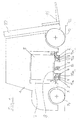
- Figure 1 shows an inventive truck formed by a counterbalance forklift 1 truck in side view.
- the counterbalance forklift 1 has a telescopically extendable mast 10 and a load-bearing means 11 movably guided in the vertical direction.
- the counterbalance forklift 1 On a roadway 12 is the counterbalance forklift 1 with two front wheels 13 and two rear wheels 14.
- a battery block 5 which is used to supply the electrical units, in particular the driving and lifting drive of the counterbalance forklift 1 is used with electrical energy.
- the battery block 5 can be removed from the battery compartment 7 in the transverse direction of the counterbalance forklift 1-in the present illustration, ie in the direction perpendicular to the plane of the drawing.
- the horizontal displaceability of the battery block 5 is made possible according to the invention in that the battery block 5 stands on a displaceable contact surface 8.
- a guide is provided which allows horizontal movement in the transverse direction of the counterbalance forklift 1.
- the guide comprises two guide rails 2 fastened to a vehicle frame 9 of the counterbalance forklift 1, two guide rails 4 fastened to the contact surface 8 and two roller supports 3 with rollers 15a, 15b.
- the outer rollers 15a of the roller carrier are guided in the guide rails 2 on the vehicle frame 9, while the inner rollers 15 are guided in the guide rails 4 on the footprint 8.
- the battery compartment 7 is shown with extended footprint 8 in plan view.
- the roller carriers 3 with the rollers 15a and 15b and the guide rails 2 for the rollers 15a can also be seen.
- the leadership realized with these components leadership of the footprint 8 allows horizontal movement of the footprint 6 in the transverse direction 17 of the counterweight forklift 1, wherein the roller carrier 3 also moves in the direction 17.
- fully extended position of the footprint 8 are still two pairs of rollers 15a within the guide rails 2, so that a torque can be transmitted from the roller carrier 3 to the guide rails 2 and thus tilting of the footprint 8 is prevented.
- some of the weight forces of the footprint 8 and the battery pack located thereon are also supported directly on the support 16 and the support roller 6 on the road.
- the footprint 8 In the illustrated, extended position, the footprint 8 is well out of the battery compartment and is spaced approximately 100 millimeters from a sidewall 19 of the counterbalance forklift.
- the maximum movement path of the footprint 8 is thus 100 millimeters longer than the length I of the footprint, which corresponds to the length of the battery pack.
- the extended footprint 8 is thus freely accessible from above, so that the battery pack can be parked for example by means of a crane or by means of another forklift on the footprint 8 or lifted from the footprint 8.
Landscapes
- Engineering & Computer Science (AREA)
- Transportation (AREA)
- Mechanical Engineering (AREA)
- Structural Engineering (AREA)
- Combustion & Propulsion (AREA)
- Chemical & Material Sciences (AREA)
- Civil Engineering (AREA)
- Life Sciences & Earth Sciences (AREA)
- Geology (AREA)
- Forklifts And Lifting Vehicles (AREA)
- Electric Propulsion And Braking For Vehicles (AREA)
- Battery Mounting, Suspending (AREA)
- Vehicle Cleaning, Maintenance, Repair, Refitting, And Outriggers (AREA)
- Arrangement Or Mounting Of Propulsion Units For Vehicles (AREA)
Abstract
Description
- Die Erfindung betrifft ein Flurförderzeug, insbesondere Gegengewichtsgabelstapler, mit einem innerhalb eines Fahrzeugrahmens angeordneten Batterieblock, der zum Durchführen eines Batteriewechsels relativ zum Fahrzeugrahmen in horizontaler Richtung bewegbar ist.
- Flurförderzeuge mit einer seitlichen Batterieentnahmeöffnung sind häufig mit einer Rollenbahn ausgerüstet, auf der ein Batterieblock mit relativ geringem Kraftaufwand verschoben werden kann. Um den Batterieblock vollständig aus dem Batteriefach heraus bewegen zu können, wird bei Flurförderzeugen des Standes der Technik neben dem Flurförderzeug eine externe Rollenbahn angeordnet, die dann an die zu dem Flurförderzeug gehörende Rollenbahn anschließt. Alternativ ist es bekannt, die in dem Flurförderzeug angeordnete Rollenbahn ausziehbar zu gestalten. Zur Durchführung eines Batteriewechsels wird dabei zuerst die Rollenbahn ausgezogen und anschließend wird der Batterieblock auf der ausgezogenen Rollenbahn vollständig aus dem Batteriefach heraus bewegt. Eine solche Anordnung ist beispielsweise in der DE 102 41 418 A1 beschrieben. Der vollständig aus dem Batteriefach des Flurförderzeugs heraus bewegte Batterieblock kann dann beispielsweise mit einem Hallenkran angehoben und weiter transportiert werden. Ein Einsetzen eines neuen Batterieblocks in das Flurförderzeug erfolgt in umgekehrter Reihenfolge.
- Der vorliegenden Erfindung liegt die Aufgabe zugrunde, ein Flurförderzeug mit einer anderen, einfach aufgebauten und sicheren Vorrichtung zur seitlichen Batterieentnahme zur Verfügung zu stellen.
- Diese Aufgabe wird erfindungsgemäß dadurch gelöst, dass das Flurförderzeug eine in horizontaler Richtung bewegbare, an dem Fahrzeugrahmen geführte Aufstandsfläche für den Batterieblock aufweist. Der Batterieblock steht auf der Aufstandsfläche und kann gemeinsam mit der Aufstandsfläche in horizontaler Richtung aus dem Batteriefach heraus oder in das Batteriefach hinein bewegt werden. Eine Relativbewegung zwischen Batterieblock und Aufstandsfläche findet dabei nicht statt.
- Vorteilhafterweise ist die Aufstandsfläche vollständig aus dem Flurförderzeug heraus bewegbar. Wenn sich die Aufstandsfläche vollständig außerhalb des Flurförderzeugs befindet, ist auch der Batterieblock vollständig außerhalb des Flurförderzeugs angeordnet und kann dann beispielsweise mit einem Kran senkrecht angehoben werden.
- Um zu erreichen, dass der Batterieblock bei eingefahrener Aufstandsfläche vollständig innerhalb des Flurförderzeugs und bei ausgefahrener Aufstandsfläche vollständig außerhalb des Flurförderzeugs angeordnet ist, ist der Bewegungsweg der Aufstandsfläche größer ist als die Erstreckung des Batterieblocks in Bewegungsrichtung der Aufstandsfläche.
- Vorzugsweise ist der maximale Bewegungsweg der Aufstandsfläche um mindestens 50 Millimeter, vorzugsweise um mindestens 80 Millimeter größer als die Erstreckung des Batterieblocks in Bewegungsrichtung der Aufstandsfläche.
- Gemäß einer zweckmäßigen Ausgestaltung der Erfindung ist zur Führung der Aufstandsfläche mindestens ein sich in horizontaler Richtung erstreckender Rollenträger vorgesehen, an dem mehrere Rollen drehbar gelagert sind. Die Rollen des Rollenträgers ermöglichen die horizontale Beweglichkeit der Aufstandsfläche und dienen gleichzeitig zur Führung der Aufstandsfläche.
- Hierfür ist der Rollenträger mittels der Rollen in mindestens einer an dem Fahrzeugrahmen angeordneten Führungsschiene bewegbar geführt. Die Führungsschiene ist direkt oder indirekt an dem Fahrzeugrahmen, also dem tragenden Bauteil des Flurförderzeugs befestigt. Die Rollen des Rollenträgers sind in dieser Führungsschiene bewegbar geführt.
- Weiter weist die Aufstandsfläche mindestens eine Führungsschiene auf, mit der die Aufstandsfläche an den Rollen des Rollenträgers bewegbar geführt ist. Die Führungsschiene der Aufstandsfläche kann damit relativ zum Rollenträger in horizontaler Richtung bewegt werden. Die auf die Aufstandsfläche wirkenden Kräfte werden - soweit sie nicht über die Stütze an der Fahrbahn abgestützt werden - über den Rollenträger in den Fahrzeugrahmen des Flurförderzeugs eingeleitet.
- Gemäß einer Weiterbildung der Erfindung weist die Aufstandsfläche und/oder der Rollenträger eine ausfahrbare Stütze auf, mit der die ausgefahrene Aufstandsfläche gegenüber einer Fahrbahn abstützbar ist. Die Stütze verhindert ein Umkippen des Flurförderzeugs infolge der Gewichtskraft des Batterieblocks, wenn sich der Batterieblock auf der ausgefahrenen Aufstandsfläche neben dem Batteriefach befindet. Während sich die Aufstandsfläche innerhalb des Batteriefachs befindet, ist die Stütze eingefahren und benötigt dabei nur wenig Bauraum in vertikaler Richtung. Wenn sich die Aufstandsfläche hingegen außerhalb des Batteriefachs befindet, ist die Stütze ausgefahren stützt die Aufstandsfläche nach unten an der Fahrbahn ab.
- Mit besonderem Vorteil weist die Stütze mindestens eine Stützrolle auf, die während des Bewegens der Aufstandsfläche auf der Fahrbahn abrollt. Die mit der Stützrolle ausgerüstete Stütze ermöglicht ein Abstützen der Aufstandsfläche während der horizontalen Bewegung der Aufstandsfläche, wenn sich die Stütze außerhalb des Batteriefachs befindet. Solange sich die Stütze innerhalb des Batteriefachs befindet, befindet sich auch der Schwerpunkt des Batterieblocks innerhalb des Batteriefachs und eine Abstützung an der Fahrbahn ist nicht erforderlich. Während des Bewegens der Aufstandsfläche mit ausgefahrener Stütze bleibt die Position der Stütze relativ zur Aufstandsfläche unverändert.
- Weitere Vorteile und Einzelheiten der Erfindung werden anhand des in den schematischen Figuren dargestellten Ausführungsbeispiels näher erläutert. Dabei zeigt
- Figur 1
- ein erfindungsgemäßes Flurförderzeug in Seitenansicht,
- Figur 2
- ein Batteriefach mit ausgefahrener Aufstandsfläche in Draufsicht.
- Figur 1 zeigt ein von einem Gegengewichtsgabelstapler 1 gebildetes erfindungsgemäßes Flurförderzeug in Seitenansicht. Am vorderen Ende weist der Gegengewichtsgabelstapler 1 ein teleskopisch ausfahrbares Hubgerüst 10 und ein daran in vertikaler Richtung bewegbar geführtes Lastaufnahmemittel 11 auf. Auf einer Fahrbahn 12 steht der Gegengewichtsgabelstapler 1 mit zwei Vorderrädem 13 und zwei Hinterrädern 14 auf.
- In einem zur Seite des Gegengewichtsgabelstaplers 1 offenen Batteriefach 7 befindet sich ein Batterieblock 5, der zur Versorgung der elektrischen Aggregate, insbesondere des Fahr- und des Hubantriebs des Gegengewichtsgabelstaplers 1 mit elektrischer Energie dient. Der Batterieblock 5 kann in Querrichtung des Gegengewichtsgabelstaplers 1 - in der vorliegenden Darstellung also in Richtung senkrecht zur Zeichenebene - aus dem Batteriefach 7 entnommen werden.
- Die horizontale Verschiebbarkeit des Batterieblocks 5 wird erfindungsgemäß dadurch ermöglicht, dass der Batterieblock 5 auf einer verschiebbaren Aufstandsfläche 8 steht. Zur verschiebbaren Lagerung der Aufstandsfläche 8 ist eine Führung vorgesehen, die eine horizontale Bewegung in Querrichtung des Gegengewichtsgabelstaplers 1 ermöglicht. Die Führung umfasst im vorliegenden Ausführungsbeispiel zwei an einem Fahrzeugrahmen 9 des Gegengewichtsgabelstaplers 1 befestigte Führungsschienen 2, zwei an der Aufstandsfläche 8 befestigte Führungsschienen 4 und zwei Rollenträger 3 mit Rollen 15a, 15b. Hierbei sind die äußeren Rollen 15a des Rollenträgers in den Führungsschienen 2 am Fahrzeugrahmen 9 geführt, während die inneren Rollen 15 in den Führungsschienen 4 an der Aufstandsfläche 8 geführt sind.
- Weiter weist die Aufstandsfläche 8 eine ausfahrbare Stütze 16 mit einer Stützrolle 6 auf. Wenn sich die Aufstandsfläche 8 innerhalb des Gegengewichtsgabelstaplers 1 befindet, ist die Stütze 16 nach oben geklappt und benötigt damit nur wenig Bauraum in vertikaler Richtung. Wenn die Aufstandsfläche 8 hingegen so weit ausgezogen ist, dass sich die Stütze 16 außerhalb des Gegengewichtsgabelstaplers 1 befindet, kann die Stütze 16 herunter geklappt und verriegelt werden, sodass die Stützrolle 6 auf der Fahrbahn 12 abrollt und die Gewichtskraft des Batterieblocks 5 zumindest teilweise über die Stütze 16 und die Stützrolle 6 an der Fahrbahn 12 abgestützt wird. Hierdurch wird insbesondere dann, wenn sich der Schwerpunkt des Batterieblocks 5 außerhalb des Gegengewichtsgabelstaplers befindet, ein Umkippen des Gegengewichtsgabelstaplers 1 verhindert.
- In Figur 2 ist das Batteriefach 7 mit ausgefahrener Aufstandsfläche 8 in Draufsicht dargestellt. Zu erkennen sind weiter die Rollenträger 3 mit den Rollen 15a und 15b sowie die Führungsschienen 2 für die Rollen 15a. Die mit diesen Bauteilen realisierte Führung der Aufstandsfläche 8 ermöglicht eine horizontale Bewegung der Aufstandsfläche 6 in Querrichtung 17 des Gegengewichtsgabelstaplers 1, wobei sich der Rollenträger 3 ebenfalls in Richtung 17 bewegt. In der dargestellten, vollständig ausgefahrenen Position der Aufstandsfläche 8 befinden sich noch zwei Rollenpaare 15a innerhalb der Führungsschienen 2, sodass von dem Rollenträger 3 auf die Führungsschienen 2 ein Drehmoment übertragen werden kann und damit ein Abkippen der Aufstandsfläche 8 verhindert ist. Teilweise werden die Gewichtskräfte der Aufstandsfläche 8 und des darauf befindlichen Batterieblocks jedoch auch direkt über die Stütze 16 und die Stützrolle 6 auf der Fahrbahn abgestützt.
- In der dargestellten, ausgefahrenen Position befindet sich die Aufstandsfläche 8 deutlich außerhalb des Batteriefachs und ist ca. 100 Millimeter von einer Seitenwand 19 des Gegengewichtsgabelstaplers beabstandet. Der maximale Bewegungsweg der Aufstandsfläche 8 ist damit um 100 Millimeter länger als die Länge I der Aufstandsfläche, die der Länge des Batterieblocks entspricht. Die ausgefahrene Aufstandsfläche 8 ist damit von oben frei zugänglich, sodass der Batterieblock beispielsweise mittels eines Krans oder mittels eines weiteren Gabelstaplers auf der Aufstandsfläche 8 abgestellt oder von der Aufstandsfläche 8 abgehoben werden kann.
Claims (9)
- Flurförderzeug, insbesondere Gegengewichtsgabelstapler (1), mit einem innerhalb eines Fahrzeugrahmens (9) angeordneten Batterieblock (5), der zum Durchführen eines Batteriewechsels relativ zum Fahrzeugrahmen (9) in horizontaler Richtung bewegbar ist, dadurch gekennzeichnet, dass das Flurförderzeug eine in horizontaler Richtung bewegbare, an dem Fahrzeugrahmen (9) geführte Aufstandsfläche (8) für den Batterieblock (5) aufweist.
- Flurförderzeug nach Anspruch 1, dadurch gekennzeichnet, dass die Aufstandsfläche (8) vollständig aus dem Flurförderzeug heraus bewegbar ist.
- Flurförderzeug nach Anspruch 1 oder 2, dadurch gekennzeichnet, dass der maximale Bewegungsweg der Aufstandsfläche (8) größer ist als die Erstreckung des Batterieblocks (5) in Bewegungsrichtung der Aufstandsfläche (8).
- Flurförderzeug nach Anspruch 3, dadurch gekennzeichnet, dass der maximale Bewegungsweg der Aufstandsfläche (8) um mindestens 50 Millimeter, vorzugsweise um mindestens 80 Millimeter größer ist als die Erstreckung des Batterieblocks (5) in Bewegungsrichtung der Aufstandsfläche (8).
- Flurförderzeug nach einem der Ansprüche 1 bis 4, dadurch gekennzeichnet, dass zur Führung der Aufstandsfläche (8) mindestens ein sich in horizontaler Richtung erstreckender Rollenträger (3) vorgesehen ist, an dem mehrere Rollen (15a, 15b) drehbar gelagert sind.
- Flurförderzeug nach Anspruch 5, dadurch gekennzeichnet, dass der Rollenträger (3) mittels der Rollen (15a) in mindestens einer an dem Fahrzeugrahmen (9) angeordneten Führungsschiene (2) bewegbar geführt ist.
- Flurförderzeug nach Anspruch 5 oder 6, dadurch gekennzeichnet, dass die Aufstandsfläche (8) mindestens eine Führungsschiene (4) aufweist, mit der die Aufstandsfläche (8) an den Rollen (15b) des Rollenträgers (3) bewegbar geführt ist.
- Flurförderzeug nach einem der Ansprüche 1 bis 7, dadurch gekennzeichnet, dass die Aufstandsfläche (8) und/oder der Rollenträger (3) eine ausfahrbare Stütze (16) aufweist, mit der die ausgefahrene Aufstandsfläche (8) gegenüber einer Fahrbahn (12) abstützbar ist.
- Flurförderzeug nach Anspruch 8, dadurch gekennzeichnet, dass die Stütze (16) mindestens eine Stützrolle (6) aufweist, die während des Bewegens der Aufstandsfläche (8) auf der Fahrbahn (12) abrollt.
Applications Claiming Priority (1)
| Application Number | Priority Date | Filing Date | Title |
|---|---|---|---|
| DE102004056624A DE102004056624A1 (de) | 2004-11-24 | 2004-11-24 | Flurförderzeug mit einer bewegbaren Aufstandsfläche für einen Batterieblock |
Publications (2)
| Publication Number | Publication Date |
|---|---|
| EP1661847A1 true EP1661847A1 (de) | 2006-05-31 |
| EP1661847B1 EP1661847B1 (de) | 2008-06-18 |
Family
ID=35788542
Family Applications (1)
| Application Number | Title | Priority Date | Filing Date |
|---|---|---|---|
| EP05024302A Expired - Lifetime EP1661847B1 (de) | 2004-11-24 | 2005-11-08 | Flurförderzeug mit einer bewegbaren Aufstandsfläche für einen Batterieblock |
Country Status (3)
| Country | Link |
|---|---|
| EP (1) | EP1661847B1 (de) |
| AT (1) | ATE398597T1 (de) |
| DE (2) | DE102004056624A1 (de) |
Cited By (6)
| Publication number | Priority date | Publication date | Assignee | Title |
|---|---|---|---|---|
| EP1780170A1 (de) * | 2005-10-25 | 2007-05-02 | Still Gmbh | Flutförderzeug mit einer bewegbaren Aufstandsfläche für einen Batterieblock |
| EP1925513A1 (de) * | 2006-11-23 | 2008-05-28 | Still Gmbh | Flurförderzeug mit einer Vorrichtung zum seitlichen Ausziehen einer Energieversorgungseinheit |
| EP1925512A1 (de) * | 2006-11-23 | 2008-05-28 | Still Gmbh | Flurförderzeug mit seitlich entnehmbarer Batterie |
| EP1925588A2 (de) | 2006-11-23 | 2008-05-28 | Still Gmbh | Gabelstapler mit einer Führung zum seitlichen Ausziehen eines Batterieblocks |
| EP2011761A2 (de) | 2007-07-05 | 2009-01-07 | Jungheinrich Aktiengesellschaft | Flurförderzeug, insbesondere Gabelstapler |
| CN113459884A (zh) * | 2021-08-16 | 2021-10-01 | 苏州阿福机器人有限公司 | 一种电动车电池更换系统 |
Families Citing this family (4)
| Publication number | Priority date | Publication date | Assignee | Title |
|---|---|---|---|---|
| DE102007025332B4 (de) * | 2007-05-31 | 2025-05-28 | Jungheinrich Aktiengesellschaft | Flurförderzeug, insbesondere Gabelstapler |
| EP2718221B1 (de) | 2011-06-07 | 2017-03-29 | Crown Equipment Corporation | Batterieübertragungsvorrichtung |
| DE102012105456A1 (de) | 2012-06-22 | 2013-12-24 | Still Gmbh | Flurförderzeug mit einem seitlichen Wechsel einer Energieversorgungseinheit |
| DE102013216399A1 (de) | 2013-08-19 | 2015-02-19 | Jungheinrich Aktiengesellschaft | Batteriebetriebenes Arbeitsfahrzeug, insbesondere Flurförderzeug |
Citations (5)
| Publication number | Priority date | Publication date | Assignee | Title |
|---|---|---|---|---|
| US3838745A (en) * | 1971-12-23 | 1974-10-01 | F Kappei | Mounting support for the battery box in the carriage of battery driven vehicles |
| GB2091179A (en) * | 1981-01-20 | 1982-07-28 | Jungheinrich Kg | Lift truck |
| JPH08165094A (ja) * | 1994-12-09 | 1996-06-25 | Nippon Yusoki Co Ltd | 産業車両のバッテリーテーブル |
| DE10241418A1 (de) | 2002-09-06 | 2004-03-18 | Still Gmbh | Flurförderzeug mit einer seitlichen Batterieentnahmeöffnung |
| DE10240854A1 (de) * | 2002-09-04 | 2004-03-18 | Still Gmbh | Flurförderzeug mit einem auf einer Rollbahn angeordneten Batterieblock |
-
2004
- 2004-11-24 DE DE102004056624A patent/DE102004056624A1/de not_active Withdrawn
-
2005
- 2005-11-08 DE DE502005004440T patent/DE502005004440D1/de not_active Expired - Lifetime
- 2005-11-08 EP EP05024302A patent/EP1661847B1/de not_active Expired - Lifetime
- 2005-11-08 AT AT05024302T patent/ATE398597T1/de not_active IP Right Cessation
Patent Citations (5)
| Publication number | Priority date | Publication date | Assignee | Title |
|---|---|---|---|---|
| US3838745A (en) * | 1971-12-23 | 1974-10-01 | F Kappei | Mounting support for the battery box in the carriage of battery driven vehicles |
| GB2091179A (en) * | 1981-01-20 | 1982-07-28 | Jungheinrich Kg | Lift truck |
| JPH08165094A (ja) * | 1994-12-09 | 1996-06-25 | Nippon Yusoki Co Ltd | 産業車両のバッテリーテーブル |
| DE10240854A1 (de) * | 2002-09-04 | 2004-03-18 | Still Gmbh | Flurförderzeug mit einem auf einer Rollbahn angeordneten Batterieblock |
| DE10241418A1 (de) | 2002-09-06 | 2004-03-18 | Still Gmbh | Flurförderzeug mit einer seitlichen Batterieentnahmeöffnung |
Non-Patent Citations (1)
| Title |
|---|
| PATENT ABSTRACTS OF JAPAN vol. 1996, no. 10 31 October 1996 (1996-10-31) * |
Cited By (10)
| Publication number | Priority date | Publication date | Assignee | Title |
|---|---|---|---|---|
| EP1780170A1 (de) * | 2005-10-25 | 2007-05-02 | Still Gmbh | Flutförderzeug mit einer bewegbaren Aufstandsfläche für einen Batterieblock |
| EP1925513A1 (de) * | 2006-11-23 | 2008-05-28 | Still Gmbh | Flurförderzeug mit einer Vorrichtung zum seitlichen Ausziehen einer Energieversorgungseinheit |
| EP1925512A1 (de) * | 2006-11-23 | 2008-05-28 | Still Gmbh | Flurförderzeug mit seitlich entnehmbarer Batterie |
| EP1925588A2 (de) | 2006-11-23 | 2008-05-28 | Still Gmbh | Gabelstapler mit einer Führung zum seitlichen Ausziehen eines Batterieblocks |
| EP1925588A3 (de) * | 2006-11-23 | 2009-09-23 | Still Gmbh | Gabelstapler mit einer Führung zum seitlichen Ausziehen eines Batterieblocks |
| EP2011761A2 (de) | 2007-07-05 | 2009-01-07 | Jungheinrich Aktiengesellschaft | Flurförderzeug, insbesondere Gabelstapler |
| EP2011761A3 (de) * | 2007-07-05 | 2009-01-21 | Jungheinrich Aktiengesellschaft | Flurförderzeug, insbesondere Gabelstapler |
| US8191688B2 (en) | 2007-07-05 | 2012-06-05 | Jungheinrich Aktiengesellschaft | Industrial truck with exchangeable battery block |
| CN101337649B (zh) * | 2007-07-05 | 2013-09-11 | 容海因里希股份公司 | 地面输送机械,特别是叉车 |
| CN113459884A (zh) * | 2021-08-16 | 2021-10-01 | 苏州阿福机器人有限公司 | 一种电动车电池更换系统 |
Also Published As
| Publication number | Publication date |
|---|---|
| ATE398597T1 (de) | 2008-07-15 |
| EP1661847B1 (de) | 2008-06-18 |
| DE502005004440D1 (de) | 2008-07-31 |
| DE102004056624A1 (de) | 2006-06-01 |
Similar Documents
| Publication | Publication Date | Title |
|---|---|---|
| EP1415874B1 (de) | Batteriewechselsystem für ein Flurförderzeug | |
| EP2719653A1 (de) | Motorisch in vertikaler Richtung höhenverstellbarer Hubtisch, z. B. zur Verwendung im Karosseriebau der Kfz-Industrie | |
| WO2014005790A1 (de) | Hebevorrichtung und verfahren zur montage und demontage eines rades mit einer solchen hebevorrichtung | |
| DE102004052067A1 (de) | Batteriewechselsystem für ein Flurförderzeug | |
| EP1661847B1 (de) | Flurförderzeug mit einer bewegbaren Aufstandsfläche für einen Batterieblock | |
| EP1396466B1 (de) | Flurförderzeug mit einer seitlichen Batterieentnahmeöffnung | |
| EP2248758B1 (de) | Flurförderzeug, insbesondere Gegengewichtsgabelstapler | |
| DE102005053305A1 (de) | Flurförderzeug mit einer Batterietür und einer Vertikalstütze | |
| EP1925588B9 (de) | Gabelstapler mit einer Führung zum seitlichen Ausziehen eines Batterieblocks | |
| EP2433896B1 (de) | Flurförderzeug, insbesondere Gegengewichtsgabelstapler | |
| DE102012105456A1 (de) | Flurförderzeug mit einem seitlichen Wechsel einer Energieversorgungseinheit | |
| DE2557769A1 (de) | Zwischenbehaelterwagen fuer metall-, insbesondere stahlstranggiessanlagen | |
| EP1690823B1 (de) | Flurförderzeug | |
| DE102006061071A1 (de) | Gabelstapler mit einer Führung zur seitlichen Batterieentnahme | |
| EP3147255B1 (de) | Wechselvorrichtung für traktionsbatterie eines flurförderzeugs | |
| DE102005022094A1 (de) | Flurförderzeug mit einem seitlich ausziehbaren Batterieblock | |
| DE102015116346A1 (de) | Wechselvorrichtung für Traktionsbatterie eines Flurförderzeugs | |
| DE102015122455A1 (de) | Flurförderzeug | |
| DE102004002548B3 (de) | Wechseleinheit für die Batterie eines Flurförderzeugs | |
| DE19700272B4 (de) | Flurförderzeug, insbesondere deichselgeführtes Flurförderzeug | |
| EP1780170B1 (de) | Flutförderzeug mit einer bewegbaren Aufstandsfläche für einen Batterieblock | |
| EP0742328A1 (de) | Wagen für eine mechanische Autoparkanlage | |
| DE102019001682B4 (de) | Fahrzeug, insbesondere Wohnmobil | |
| DE102019001681B4 (de) | Fahrzeug und Rampe hierfür | |
| DE102011018800A1 (de) | Flurförderzeug |
Legal Events
| Date | Code | Title | Description |
|---|---|---|---|
| PUAI | Public reference made under article 153(3) epc to a published international application that has entered the european phase |
Free format text: ORIGINAL CODE: 0009012 |
|
| AK | Designated contracting states |
Kind code of ref document: A1 Designated state(s): AT BE BG CH CY CZ DE DK EE ES FI FR GB GR HU IE IS IT LI LT LU LV MC NL PL PT RO SE SI SK TR |
|
| AX | Request for extension of the european patent |
Extension state: AL BA HR MK YU |
|
| 17P | Request for examination filed |
Effective date: 20060711 |
|
| 17Q | First examination report despatched |
Effective date: 20060821 |
|
| AKX | Designation fees paid |
Designated state(s): AT BE BG CH CY CZ DE DK EE ES FI FR GB GR HU IE IS IT LI LT LU LV MC NL PL PT RO SE SI SK TR |
|
| 17Q | First examination report despatched |
Effective date: 20060821 |
|
| GRAP | Despatch of communication of intention to grant a patent |
Free format text: ORIGINAL CODE: EPIDOSNIGR1 |
|
| GRAS | Grant fee paid |
Free format text: ORIGINAL CODE: EPIDOSNIGR3 |
|
| GRAA | (expected) grant |
Free format text: ORIGINAL CODE: 0009210 |
|
| AK | Designated contracting states |
Kind code of ref document: B1 Designated state(s): AT BE BG CH CY CZ DE DK EE ES FI FR GB GR HU IE IS IT LI LT LU LV MC NL PL PT RO SE SI SK TR |
|
| REG | Reference to a national code |
Ref country code: GB Ref legal event code: FG4D Free format text: NOT ENGLISH |
|
| REF | Corresponds to: |
Ref document number: 502005004440 Country of ref document: DE Date of ref document: 20080731 Kind code of ref document: P |
|
| REG | Reference to a national code |
Ref country code: CH Ref legal event code: EP |
|
| REG | Reference to a national code |
Ref country code: IE Ref legal event code: FG4D Free format text: LANGUAGE OF EP DOCUMENT: GERMAN |
|
| PG25 | Lapsed in a contracting state [announced via postgrant information from national office to epo] |
Ref country code: FI Free format text: LAPSE BECAUSE OF FAILURE TO SUBMIT A TRANSLATION OF THE DESCRIPTION OR TO PAY THE FEE WITHIN THE PRESCRIBED TIME-LIMIT Effective date: 20080618 Ref country code: SI Free format text: LAPSE BECAUSE OF FAILURE TO SUBMIT A TRANSLATION OF THE DESCRIPTION OR TO PAY THE FEE WITHIN THE PRESCRIBED TIME-LIMIT Effective date: 20080618 |
|
| PG25 | Lapsed in a contracting state [announced via postgrant information from national office to epo] |
Ref country code: NL Free format text: LAPSE BECAUSE OF FAILURE TO SUBMIT A TRANSLATION OF THE DESCRIPTION OR TO PAY THE FEE WITHIN THE PRESCRIBED TIME-LIMIT Effective date: 20080618 Ref country code: PL Free format text: LAPSE BECAUSE OF FAILURE TO SUBMIT A TRANSLATION OF THE DESCRIPTION OR TO PAY THE FEE WITHIN THE PRESCRIBED TIME-LIMIT Effective date: 20080618 Ref country code: LV Free format text: LAPSE BECAUSE OF FAILURE TO SUBMIT A TRANSLATION OF THE DESCRIPTION OR TO PAY THE FEE WITHIN THE PRESCRIBED TIME-LIMIT Effective date: 20080618 |
|
| NLV1 | Nl: lapsed or annulled due to failure to fulfill the requirements of art. 29p and 29m of the patents act | ||
| PG25 | Lapsed in a contracting state [announced via postgrant information from national office to epo] |
Ref country code: CZ Free format text: LAPSE BECAUSE OF FAILURE TO SUBMIT A TRANSLATION OF THE DESCRIPTION OR TO PAY THE FEE WITHIN THE PRESCRIBED TIME-LIMIT Effective date: 20080618 Ref country code: IS Free format text: LAPSE BECAUSE OF FAILURE TO SUBMIT A TRANSLATION OF THE DESCRIPTION OR TO PAY THE FEE WITHIN THE PRESCRIBED TIME-LIMIT Effective date: 20081018 Ref country code: LT Free format text: LAPSE BECAUSE OF FAILURE TO SUBMIT A TRANSLATION OF THE DESCRIPTION OR TO PAY THE FEE WITHIN THE PRESCRIBED TIME-LIMIT Effective date: 20080618 Ref country code: SE Free format text: LAPSE BECAUSE OF FAILURE TO SUBMIT A TRANSLATION OF THE DESCRIPTION OR TO PAY THE FEE WITHIN THE PRESCRIBED TIME-LIMIT Effective date: 20080918 Ref country code: PT Free format text: LAPSE BECAUSE OF FAILURE TO SUBMIT A TRANSLATION OF THE DESCRIPTION OR TO PAY THE FEE WITHIN THE PRESCRIBED TIME-LIMIT Effective date: 20081118 Ref country code: ES Free format text: LAPSE BECAUSE OF FAILURE TO SUBMIT A TRANSLATION OF THE DESCRIPTION OR TO PAY THE FEE WITHIN THE PRESCRIBED TIME-LIMIT Effective date: 20080929 |
|
| REG | Reference to a national code |
Ref country code: IE Ref legal event code: FD4D |
|
| PG25 | Lapsed in a contracting state [announced via postgrant information from national office to epo] |
Ref country code: RO Free format text: LAPSE BECAUSE OF FAILURE TO SUBMIT A TRANSLATION OF THE DESCRIPTION OR TO PAY THE FEE WITHIN THE PRESCRIBED TIME-LIMIT Effective date: 20080618 Ref country code: SK Free format text: LAPSE BECAUSE OF FAILURE TO SUBMIT A TRANSLATION OF THE DESCRIPTION OR TO PAY THE FEE WITHIN THE PRESCRIBED TIME-LIMIT Effective date: 20080618 |
|
| PLBE | No opposition filed within time limit |
Free format text: ORIGINAL CODE: 0009261 |
|
| STAA | Information on the status of an ep patent application or granted ep patent |
Free format text: STATUS: NO OPPOSITION FILED WITHIN TIME LIMIT |
|
| PG25 | Lapsed in a contracting state [announced via postgrant information from national office to epo] |
Ref country code: IE Free format text: LAPSE BECAUSE OF FAILURE TO SUBMIT A TRANSLATION OF THE DESCRIPTION OR TO PAY THE FEE WITHIN THE PRESCRIBED TIME-LIMIT Effective date: 20080618 Ref country code: DK Free format text: LAPSE BECAUSE OF FAILURE TO SUBMIT A TRANSLATION OF THE DESCRIPTION OR TO PAY THE FEE WITHIN THE PRESCRIBED TIME-LIMIT Effective date: 20080618 Ref country code: BG Free format text: LAPSE BECAUSE OF FAILURE TO SUBMIT A TRANSLATION OF THE DESCRIPTION OR TO PAY THE FEE WITHIN THE PRESCRIBED TIME-LIMIT Effective date: 20080918 Ref country code: EE Free format text: LAPSE BECAUSE OF FAILURE TO SUBMIT A TRANSLATION OF THE DESCRIPTION OR TO PAY THE FEE WITHIN THE PRESCRIBED TIME-LIMIT Effective date: 20080618 |
|
| 26N | No opposition filed |
Effective date: 20090319 |
|
| BERE | Be: lapsed |
Owner name: STILL G.M.B.H. Effective date: 20081130 |
|
| PG25 | Lapsed in a contracting state [announced via postgrant information from national office to epo] |
Ref country code: MC Free format text: LAPSE BECAUSE OF NON-PAYMENT OF DUE FEES Effective date: 20081130 |
|
| PG25 | Lapsed in a contracting state [announced via postgrant information from national office to epo] |
Ref country code: BE Free format text: LAPSE BECAUSE OF NON-PAYMENT OF DUE FEES Effective date: 20081130 |
|
| PG25 | Lapsed in a contracting state [announced via postgrant information from national office to epo] |
Ref country code: AT Free format text: LAPSE BECAUSE OF NON-PAYMENT OF DUE FEES Effective date: 20081108 |
|
| REG | Reference to a national code |
Ref country code: CH Ref legal event code: PL |
|
| GBPC | Gb: european patent ceased through non-payment of renewal fee |
Effective date: 20091108 |
|
| PG25 | Lapsed in a contracting state [announced via postgrant information from national office to epo] |
Ref country code: CY Free format text: LAPSE BECAUSE OF FAILURE TO SUBMIT A TRANSLATION OF THE DESCRIPTION OR TO PAY THE FEE WITHIN THE PRESCRIBED TIME-LIMIT Effective date: 20080618 Ref country code: HU Free format text: LAPSE BECAUSE OF FAILURE TO SUBMIT A TRANSLATION OF THE DESCRIPTION OR TO PAY THE FEE WITHIN THE PRESCRIBED TIME-LIMIT Effective date: 20081219 Ref country code: LU Free format text: LAPSE BECAUSE OF NON-PAYMENT OF DUE FEES Effective date: 20081108 |
|
| PG25 | Lapsed in a contracting state [announced via postgrant information from national office to epo] |
Ref country code: TR Free format text: LAPSE BECAUSE OF FAILURE TO SUBMIT A TRANSLATION OF THE DESCRIPTION OR TO PAY THE FEE WITHIN THE PRESCRIBED TIME-LIMIT Effective date: 20080618 |
|
| PG25 | Lapsed in a contracting state [announced via postgrant information from national office to epo] |
Ref country code: CH Free format text: LAPSE BECAUSE OF NON-PAYMENT OF DUE FEES Effective date: 20091130 Ref country code: LI Free format text: LAPSE BECAUSE OF NON-PAYMENT OF DUE FEES Effective date: 20091130 Ref country code: GR Free format text: LAPSE BECAUSE OF FAILURE TO SUBMIT A TRANSLATION OF THE DESCRIPTION OR TO PAY THE FEE WITHIN THE PRESCRIBED TIME-LIMIT Effective date: 20080919 |
|
| PG25 | Lapsed in a contracting state [announced via postgrant information from national office to epo] |
Ref country code: GB Free format text: LAPSE BECAUSE OF NON-PAYMENT OF DUE FEES Effective date: 20091108 |
|
| REG | Reference to a national code |
Ref country code: FR Ref legal event code: PLFP Year of fee payment: 11 |
|
| REG | Reference to a national code |
Ref country code: FR Ref legal event code: PLFP Year of fee payment: 12 |
|
| REG | Reference to a national code |
Ref country code: FR Ref legal event code: PLFP Year of fee payment: 13 |
|
| PGFP | Annual fee paid to national office [announced via postgrant information from national office to epo] |
Ref country code: FR Payment date: 20221118 Year of fee payment: 18 |
|
| PGFP | Annual fee paid to national office [announced via postgrant information from national office to epo] |
Ref country code: IT Payment date: 20231130 Year of fee payment: 19 Ref country code: DE Payment date: 20231120 Year of fee payment: 19 |
|
| PG25 | Lapsed in a contracting state [announced via postgrant information from national office to epo] |
Ref country code: FR Free format text: LAPSE BECAUSE OF NON-PAYMENT OF DUE FEES Effective date: 20231130 |
|
| PG25 | Lapsed in a contracting state [announced via postgrant information from national office to epo] |
Ref country code: FR Free format text: LAPSE BECAUSE OF NON-PAYMENT OF DUE FEES Effective date: 20231130 |
|
| REG | Reference to a national code |
Ref country code: DE Ref legal event code: R119 Ref document number: 502005004440 Country of ref document: DE |
|
| PG25 | Lapsed in a contracting state [announced via postgrant information from national office to epo] |
Ref country code: DE Free format text: LAPSE BECAUSE OF NON-PAYMENT OF DUE FEES Effective date: 20250603 |
|
| PG25 | Lapsed in a contracting state [announced via postgrant information from national office to epo] |
Ref country code: IT Free format text: LAPSE BECAUSE OF NON-PAYMENT OF DUE FEES Effective date: 20241108 |