EP1661842B1 - Inputting or adjusting reference positions in a door controller - Google Patents
Inputting or adjusting reference positions in a door controller Download PDFInfo
- Publication number
- EP1661842B1 EP1661842B1 EP05108737A EP05108737A EP1661842B1 EP 1661842 B1 EP1661842 B1 EP 1661842B1 EP 05108737 A EP05108737 A EP 05108737A EP 05108737 A EP05108737 A EP 05108737A EP 1661842 B1 EP1661842 B1 EP 1661842B1
- Authority
- EP
- European Patent Office
- Prior art keywords
- door
- controller
- reference position
- memory
- track
- Prior art date
- Legal status (The legal status is an assumption and is not a legal conclusion. Google has not performed a legal analysis and makes no representation as to the accuracy of the status listed.)
- Active
Links
- 238000000034 method Methods 0.000 claims abstract description 14
- 238000012544 monitoring process Methods 0.000 claims abstract description 11
- 230000033001 locomotion Effects 0.000 claims description 16
- 238000009434 installation Methods 0.000 claims description 9
- 230000004913 activation Effects 0.000 claims 1
- 230000001133 acceleration Effects 0.000 description 2
- 230000003993 interaction Effects 0.000 description 2
- 230000011664 signaling Effects 0.000 description 2
- 230000009286 beneficial effect Effects 0.000 description 1
- 230000001419 dependent effect Effects 0.000 description 1
- 238000010586 diagram Methods 0.000 description 1
- 230000006870 function Effects 0.000 description 1
- 238000012423 maintenance Methods 0.000 description 1
- 238000005259 measurement Methods 0.000 description 1
Images
Classifications
-
- B—PERFORMING OPERATIONS; TRANSPORTING
- B66—HOISTING; LIFTING; HAULING
- B66B—ELEVATORS; ESCALATORS OR MOVING WALKWAYS
- B66B13/00—Doors, gates, or other apparatus controlling access to, or exit from, cages or lift well landings
- B66B13/02—Door or gate operation
- B66B13/14—Control systems or devices
- B66B13/143—Control systems or devices electrical
- B66B13/146—Control systems or devices electrical method or algorithm for controlling doors
-
- B—PERFORMING OPERATIONS; TRANSPORTING
- B66—HOISTING; LIFTING; HAULING
- B66B—ELEVATORS; ESCALATORS OR MOVING WALKWAYS
- B66B13/00—Doors, gates, or other apparatus controlling access to, or exit from, cages or lift well landings
- B66B13/02—Door or gate operation
- B66B13/14—Control systems or devices
- B66B13/16—Door or gate locking devices controlled or primarily controlled by condition of cage, e.g. movement or position
-
- E—FIXED CONSTRUCTIONS
- E05—LOCKS; KEYS; WINDOW OR DOOR FITTINGS; SAFES
- E05F—DEVICES FOR MOVING WINGS INTO OPEN OR CLOSED POSITION; CHECKS FOR WINGS; WING FITTINGS NOT OTHERWISE PROVIDED FOR, CONCERNED WITH THE FUNCTIONING OF THE WING
- E05F1/00—Closers or openers for wings, not otherwise provided for in this subclass
- E05F1/02—Closers or openers for wings, not otherwise provided for in this subclass gravity-actuated, e.g. by use of counterweights
- E05F1/025—Closers or openers for wings, not otherwise provided for in this subclass gravity-actuated, e.g. by use of counterweights with rectilinearly-moving counterweights
-
- E—FIXED CONSTRUCTIONS
- E05—LOCKS; KEYS; WINDOW OR DOOR FITTINGS; SAFES
- E05F—DEVICES FOR MOVING WINGS INTO OPEN OR CLOSED POSITION; CHECKS FOR WINGS; WING FITTINGS NOT OTHERWISE PROVIDED FOR, CONCERNED WITH THE FUNCTIONING OF THE WING
- E05F15/00—Power-operated mechanisms for wings
- E05F15/60—Power-operated mechanisms for wings using electrical actuators
- E05F15/603—Power-operated mechanisms for wings using electrical actuators using rotary electromotors
- E05F15/632—Power-operated mechanisms for wings using electrical actuators using rotary electromotors for horizontally-sliding wings
- E05F15/643—Power-operated mechanisms for wings using electrical actuators using rotary electromotors for horizontally-sliding wings operated by flexible elongated pulling elements, e.g. belts, chains or cables
-
- E—FIXED CONSTRUCTIONS
- E05—LOCKS; KEYS; WINDOW OR DOOR FITTINGS; SAFES
- E05Y—INDEXING SCHEME ASSOCIATED WITH SUBCLASSES E05D AND E05F, RELATING TO CONSTRUCTION ELEMENTS, ELECTRIC CONTROL, POWER SUPPLY, POWER SIGNAL OR TRANSMISSION, USER INTERFACES, MOUNTING OR COUPLING, DETAILS, ACCESSORIES, AUXILIARY OPERATIONS NOT OTHERWISE PROVIDED FOR, APPLICATION THEREOF
- E05Y2400/00—Electronic control; Electrical power; Power supply; Power or signal transmission; User interfaces
- E05Y2400/10—Electronic control
-
- E—FIXED CONSTRUCTIONS
- E05—LOCKS; KEYS; WINDOW OR DOOR FITTINGS; SAFES
- E05Y—INDEXING SCHEME ASSOCIATED WITH SUBCLASSES E05D AND E05F, RELATING TO CONSTRUCTION ELEMENTS, ELECTRIC CONTROL, POWER SUPPLY, POWER SIGNAL OR TRANSMISSION, USER INTERFACES, MOUNTING OR COUPLING, DETAILS, ACCESSORIES, AUXILIARY OPERATIONS NOT OTHERWISE PROVIDED FOR, APPLICATION THEREOF
- E05Y2900/00—Application of doors, windows, wings or fittings thereof
- E05Y2900/10—Application of doors, windows, wings or fittings thereof for buildings or parts thereof
- E05Y2900/104—Application of doors, windows, wings or fittings thereof for buildings or parts thereof for elevators
-
- G—PHYSICS
- G05—CONTROLLING; REGULATING
- G05B—CONTROL OR REGULATING SYSTEMS IN GENERAL; FUNCTIONAL ELEMENTS OF SUCH SYSTEMS; MONITORING OR TESTING ARRANGEMENTS FOR SUCH SYSTEMS OR ELEMENTS
- G05B2219/00—Program-control systems
- G05B2219/30—Nc systems
- G05B2219/45—Nc applications
- G05B2219/45242—Door, panel, window operation, opening, closing
Definitions
- the invention relates to a door controller and a method for inputting or adjusting one or more reference positions used by the door controller and, in particular, to a method for quickly teaching the controller accurate reference positions along a door travel path.
- Modern elevator door controllers use travel curves to dictate the movement of a door along a track between its closed and open positions. Such travel curves define the desired door speed as a function of the door position or of the time.
- a pulse encoder is frequently used to provide the controller with a signal indicating the door position.
- the controller implements a door opening operation during which the door is moved by a drive along a track from the closed position to a fully open position where further movement of the door in the opening direction is prevented by a mechanical stopper or alternatively by an open-limit switch mounted on the track.
- the open-limit switch when activated, signals the controller to stop the drive and thereby also restricts motion of the door along the track.
- the controller When activated, signals the controller to stop the drive and thereby also restricts motion of the door along the track.
- the controller During this learning run the total distance from the closed position to the fully open position is registered by the pulse encoder into a memory accessible by the controller. Accordingly, the total travel path for the door is known to the controller.
- Intermediate switches may be mounted along the track to signal changes in the desired travel curve to the controller (for example there may be an intermediate switch to indicate the position where the motion of the door should change from a constant creeping speed to full acceleration).
- the controller can automatically calculate these intermediate reference positions using the total travel distance and register these into the memory as discussed in JP-A-2000016730 .
- any adjustment of the reference positions is performed by manually accessing the door track and shifting the respective switches or stoppers along the track until they are in the correct positions and then instructing the controller to repeat the learning run.
- This is a laborious and time-consuming task, particularly in an elevator installation where it may have to be repeated for each individual landing of the installation.
- the task can be very frustrating if only minor adjustment is required.
- the objective of the present invention is to ease the task of adjusting the reference positions used in a controller for automatic doors and in particular to reduce the time and labour required to make the necessary adjustments.
- the fully open or any other reference position can be registered into the door controller without requiring the door to interact with any device such as a stopper or switch mounted along the door guidance track.
- any device such as a stopper or switch mounted along the door guidance track.
- the door is freely movable to any intermediate position along the door track meaning that the door is not physically obstructed (i.e. by a stopper) nor does the door interact with any means signalling the controller to restrict further motion (i.e. a limit switch), nor does the door interact with any means signalling the controller to restrict motion to a specified pattern (i.e. an intermediate switch).
- the door is freely movable between the mechanical ends of the door and the reference position may be registered at any position along the track.
- the limit switches, intermediate switches or stoppers of the prior art are superfluous to the present invention since the reference positions are registered independently of any physical restriction in, or interaction along, the door track.
- the controller is switched to a learning mode and the door is merely moved to the required position which is an unrestricted position along the track and that position as recorded by the position monitoring means is registered as a reference position.
- the controller can automatically register the reference position in memory.
- the controller verifies that there is no change in the position as recorded by the position monitoring means for a specific period of time and automatically registers this position into memory as the reference position.
- no additional equipment is required for the engineer to register the reference position in the memory.
- the door Since the door must be held in the desired position for a specific time period, it is beneficial that the door is moved by hand rather than by the door drive, otherwise the door drive would tend to continue to move the door at the desired position and the engineer would have to counteract the force developed by the drive in order to keep the door stationary.
- the door drive could be completely deenergized to facilitate manual movement. More beneficially, the control force signal to the driver could be set at a value sufficient only to overcome any biasing force acting on the door. This would make it very easy for the engineer to manually move the door to the desired position.
- an input device may be provided for the engineer to directly trigger the registration of the reference position into the memory of the controller.
- the door can be moved manually as described above or alternatively the controller could be used to automatically move the door at a slow speed such that when the door reaches the desired position, the engineer manually activates the input device. In the latter case the engineer does no need to move the door at all.
- the invention is particularly advantageous when applied to the door controller of an elevator installation since by its very nature an elevator has multiple landings each of which may require the individual input or adjustment of several reference positions. To access the door track for each landing is time consuming and labour intensive. With the present invention, the engineer need only move the door to the desired reference positions and register these in the memory without having to access the door track.
- the easiest reference position to register using the method and controller of the invention is the fully open position of the door. No measurement or judgement is required from the engineer as all he has to do is move the door until the edge of the door lies flush with the neighbouring door frame and then register this position in the memory as the fully open position.
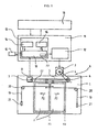
- a door controller 11 according to the present invention is illustrated in Fig. 1 .
- An elevator car 1 has a pair of door panels 2 which are driven along a track 22 by a door drive 9.
- the drive 9 has an electrical motor 3 driving a first toothed belt 4 which rotates a drive roller 6.
- the drive roller 6 drives a second toothed belt 5 which rotates a first deflecting roller 7 attached to a pulse encoder 8.
- the door panels 2 are connected to and move simultaneously with the second toothed belt 5.
- a pair of arrows P2 indicates the opening direction of movement of the door panels 2 from a central closed position X1 to the respective fully opened positions X2.
- the motor 3 is supplied with electrical energy from a power unit 12 within the controller 11.
- Each door panel 2 is connected to a closing weight 21 by a cable pull 19 which extends around a second deflecting roller 20.
- the closing weight 21 biases the panel 2 to the central closed position X1.
- the movement of the door panels 2 is controlled by a microcomputer 13 within the controller 11.
- the microcomputer 13 contains a central processor 10 communicating with a non-volatile memory register 14, a travel curve generator 16 and externally with the power unit 12.
- the pulse encoder 8 has an output connected to a central processor 10 to provide a signal representing the distance travelled by the door panels 2.
- Algorithms implemented in the travel curve generator 16 utilize the signal from the pulse encoder 8 to generate target values to control the operation of the door drive 9 via a power unit 12.
- the power unit 12 outputs a control force signal to the drive 9. This control force signal is dependent upon the position of the door panels 2 and represents the force to be applied by the drive 9 at any given moment in time to produce the desired door motion.
- the track 22 from which the car door panels 2 are suspended and guided is always manufactured to have a length sufficient to permit the doors panels 2 to open wider than actually required on-site. Accordingly, on installation of the elevator it is always necessary to adjust the factory preset opening width to that actually required X2. Furthermore, different floors of the building may have different door frames defining different opening widths, in which case the fully open position X2 of the car door panels 2 would vary between floors.
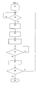
- Fig. 2 shows the structure and sequence of a routine according to the present invention to adjust the fully open position X2 for a given floor.
- This learning mode is initiated at a first step S1 by the engineer using an input device 15 connected to the microcomputer 13.
- the controller 11 opens the door partially, e.g. to 90% of the factory preset opening width S3.
- the controller 11 reduces the control force signal output to the door drive 9 for all positions of the door panels 2 in a fourth step S4. This may be accomplished by deenergizing the door drive 9.
- a timer or clock 23 within the controller 11 recognises the fact that the position signal from the encoder 8 has not changed for a specific period of time for example 3s (indicating that the door panels 2 are stationary) and triggers the controller 11 to register this positional value in the non-volatile memory register 14 as the fully open position X2 for that specific floor in a seventh step S7.
- the travel curve generator 16 using this new information, can then compute and store the most effective travel curve to control the operation of the door drive 9 for that particular floor.
- step S8 the engineer can put in a car call for another floor and repeat this procedure until the accurate, fully open positions X2 have been registered in the controller 11 for every floor of the installation.
- the engineer can terminate the learning routine using the input device 15 and the door controller 11 returns to normal operation in step S9.
- control force signal from the power unit 12 could be reduced to a constant value so that the force applied by door drive 9 is sufficient only to counteract the closing force of the biasing weights 21. This arrangement would allow the engineer to manually move the door panels 2 more easily as there is no effective biasing force acting on the panels 2.
- the sixth step S6 establishes that the door panels 2 are in the correct reference position to be registered in memory 14.
- the controller 11 may require an interaction from the engineer using the input device 15. Indeed, if the input device is used to record the reference position X2 in the memory 14, then in steps S4 and S5, the control force signal could be set to a reduced level which automatically opens the door panels 2 at a slow speed and when the door panels 2 reach the reference position X2, the engineer can simply trigger the input device 15 to record the position X2 into the memory.
- the routine can be used for registering any reference position used by the travel curve generator 16.
- the reference position could be the position along the travel path at which the driver 9, having initially moved the door panels 2 at a constant creep speed from the fully closed position, is instructed by the controller 11 to apply maximum acceleration.
- the controller and method could also be used to define the subsequent position from which the speed of the door panels 2 should be held constant and/or the position at which deceleration must be commenced to ensure the door panels 2 decelerate smoothly to the fully open position X2.
- the input device 15 could be a button (or a series of buttons if more than one reference position is to be registered in memory 14), but preferably the input device 15 is a keypad. This is particularly advantageous if more than one reference position is to be registered for each floor as the engineer can initiate the routine on a single input device for each reference position rather than pressing individual buttons.
- the doors may be biased to the fully closed position by any suitable means such as a closing weight 21 or a spring, or they may rely solely on the driver 9 to provide all intended motion.
Landscapes
- Engineering & Computer Science (AREA)
- Automation & Control Theory (AREA)
- Elevator Door Apparatuses (AREA)
- Power-Operated Mechanisms For Wings (AREA)
- Feedback Control In General (AREA)
- Elevator Control (AREA)
- Lock And Its Accessories (AREA)
Abstract
Description
- The invention relates to a door controller and a method for inputting or adjusting one or more reference positions used by the door controller and, in particular, to a method for quickly teaching the controller accurate reference positions along a door travel path.
- Modern elevator door controllers use travel curves to dictate the movement of a door along a track between its closed and open positions. Such travel curves define the desired door speed as a function of the door position or of the time. A pulse encoder is frequently used to provide the controller with a signal indicating the door position. Such a system is described in
EP-A1-0665182 . In an initial learning run, the controller implements a door opening operation during which the door is moved by a drive along a track from the closed position to a fully open position where further movement of the door in the opening direction is prevented by a mechanical stopper or alternatively by an open-limit switch mounted on the track. Whereas the stopper physically restricts motion of the door along the track, the open-limit switch, when activated, signals the controller to stop the drive and thereby also restricts motion of the door along the track. During this learning run the total distance from the closed position to the fully open position is registered by the pulse encoder into a memory accessible by the controller. Accordingly, the total travel path for the door is known to the controller. Intermediate switches may be mounted along the track to signal changes in the desired travel curve to the controller (for example there may be an intermediate switch to indicate the position where the motion of the door should change from a constant creeping speed to full acceleration). Alternatively, the controller can automatically calculate these intermediate reference positions using the total travel distance and register these into the memory as discussed inJP-A-2000016730 - After initial installation, it is important to make adjustments to the reference positions so as to compensate for mechanical tolerances and most importantly to ensure that the edge of the fully open door is flush with the door jamb. Adjustment may also be required during modernization or maintenance of the elevator installation.
- Conventionally, any adjustment of the reference positions is performed by manually accessing the door track and shifting the respective switches or stoppers along the track until they are in the correct positions and then instructing the controller to repeat the learning run. This is a laborious and time-consuming task, particularly in an elevator installation where it may have to be repeated for each individual landing of the installation. Furthermore, the task can be very frustrating if only minor adjustment is required.
- Accordingly, the objective of the present invention is to ease the task of adjusting the reference positions used in a controller for automatic doors and in particular to reduce the time and labour required to make the necessary adjustments. The fully open or any other reference position can be registered into the door controller without requiring the door to interact with any device such as a stopper or switch mounted along the door guidance track. Hence, to reconfigure the controller it is no longer necessary to gain access to the track and move the stoppers or switches to a new position.
- This objective is achieved by the method and controller according to
claims - Preferably, the controller can automatically register the reference position in memory. As the door is moved to and held stationary at the desired position, the controller verifies that there is no change in the position as recorded by the position monitoring means for a specific period of time and automatically registers this position into memory as the reference position. Hence, no additional equipment is required for the engineer to register the reference position in the memory. Since the door must be held in the desired position for a specific time period, it is beneficial that the door is moved by hand rather than by the door drive, otherwise the door drive would tend to continue to move the door at the desired position and the engineer would have to counteract the force developed by the drive in order to keep the door stationary. The door drive could be completely deenergized to facilitate manual movement. More beneficially, the control force signal to the driver could be set at a value sufficient only to overcome any biasing force acting on the door. This would make it very easy for the engineer to manually move the door to the desired position.
- Alternatively, an input device may be provided for the engineer to directly trigger the registration of the reference position into the memory of the controller. In this case, the door can be moved manually as described above or alternatively the controller could be used to automatically move the door at a slow speed such that when the door reaches the desired position, the engineer manually activates the input device. In the latter case the engineer does no need to move the door at all.
- The invention is particularly advantageous when applied to the door controller of an elevator installation since by its very nature an elevator has multiple landings each of which may require the individual input or adjustment of several reference positions. To access the door track for each landing is time consuming and labour intensive. With the present invention, the engineer need only move the door to the desired reference positions and register these in the memory without having to access the door track.
- The easiest reference position to register using the method and controller of the invention is the fully open position of the door. No measurement or judgement is required from the engineer as all he has to do is move the door until the edge of the door lies flush with the neighbouring door frame and then register this position in the memory as the fully open position.
- Furthermore, since the same position monitoring means is used both during normal operation of the controller and to actually register the reference positions in the learning mode there is inherently less likelihood of error.
- The invention is herein described by way of a specific example with reference to the accompanying drawings of which:
-
Figure 1 is a schematic diagram of an elevator door controller in accordance with a preferred embodiment of the invention; and -
Figure 2 is a routine performed by the door controller ofFig. 1 in accordance with a preferred embodiment of the invention. - A
door controller 11 according to the present invention is illustrated inFig. 1 . Anelevator car 1 has a pair ofdoor panels 2 which are driven along atrack 22 by adoor drive 9. Thedrive 9 has anelectrical motor 3 driving afirst toothed belt 4 which rotates adrive roller 6. Thedrive roller 6 drives asecond toothed belt 5 which rotates a first deflecting roller 7 attached to apulse encoder 8. Thedoor panels 2 are connected to and move simultaneously with thesecond toothed belt 5. A pair of arrows P2 indicates the opening direction of movement of thedoor panels 2 from a central closed position X1 to the respective fully opened positions X2. Themotor 3 is supplied with electrical energy from apower unit 12 within thecontroller 11. Eachdoor panel 2 is connected to aclosing weight 21 by acable pull 19 which extends around a second deflectingroller 20. Theclosing weight 21 biases thepanel 2 to the central closed position X1. - The movement of the
door panels 2 is controlled by amicrocomputer 13 within thecontroller 11. Themicrocomputer 13 contains acentral processor 10 communicating with anon-volatile memory register 14, atravel curve generator 16 and externally with thepower unit 12. Thepulse encoder 8 has an output connected to acentral processor 10 to provide a signal representing the distance travelled by thedoor panels 2. Algorithms implemented in thetravel curve generator 16 utilize the signal from thepulse encoder 8 to generate target values to control the operation of thedoor drive 9 via apower unit 12. Thepower unit 12 outputs a control force signal to thedrive 9. This control force signal is dependent upon the position of thedoor panels 2 and represents the force to be applied by thedrive 9 at any given moment in time to produce the desired door motion. - An
elevator controller 18, connected to and superordinate to thedoor controller 11, initiates the opening movement of thedoor panels 2 and dispatches theelevator car 1 when the door is closed. - As a safety margin, the
track 22 from which thecar door panels 2 are suspended and guided is always manufactured to have a length sufficient to permit thedoors panels 2 to open wider than actually required on-site. Accordingly, on installation of the elevator it is always necessary to adjust the factory preset opening width to that actually required X2. Furthermore, different floors of the building may have different door frames defining different opening widths, in which case the fully open position X2 of thecar door panels 2 would vary between floors. -
Fig. 2 shows the structure and sequence of a routine according to the present invention to adjust the fully open position X2 for a given floor. This learning mode is initiated at a first step S1 by the engineer using aninput device 15 connected to themicrocomputer 13. On occurrence of the next open command, when thecar 1 reaches a requested landing in a second step S2, thecontroller 11 opens the door partially, e.g. to 90% of the factory preset opening width S3. Then thecontroller 11 reduces the control force signal output to thedoor drive 9 for all positions of thedoor panels 2 in a fourth step S4. This may be accomplished by deenergizing thedoor drive 9. The engineer, in a fifth step S5, is then able to easily shift thedoor panels 2 manually against the bias of theweights 21 until the panel edges are flush with the door frame of the given landing. In a sixth step S6, a timer orclock 23 within thecontroller 11 recognises the fact that the position signal from theencoder 8 has not changed for a specific period of time for example 3s (indicating that thedoor panels 2 are stationary) and triggers thecontroller 11 to register this positional value in thenon-volatile memory register 14 as the fully open position X2 for that specific floor in a seventh step S7. Thetravel curve generator 16, using this new information, can then compute and store the most effective travel curve to control the operation of thedoor drive 9 for that particular floor. In an eighth step S8 the engineer can put in a car call for another floor and repeat this procedure until the accurate, fully open positions X2 have been registered in thecontroller 11 for every floor of the installation. Alternatively, the engineer can terminate the learning routine using theinput device 15 and thedoor controller 11 returns to normal operation in step S9. - Instead of completely deenergizing the
door drive 9 in the fourth step S4, the control force signal from thepower unit 12 could be reduced to a constant value so that the force applied bydoor drive 9 is sufficient only to counteract the closing force of the biasingweights 21. This arrangement would allow the engineer to manually move thedoor panels 2 more easily as there is no effective biasing force acting on thepanels 2. - The sixth step S6 establishes that the
door panels 2 are in the correct reference position to be registered inmemory 14. Instead of waiting until there is no change in the positional signal from theencoder 8 as described above, thecontroller 11 may require an interaction from the engineer using theinput device 15. Indeed, if the input device is used to record the reference position X2 in thememory 14, then in steps S4 and S5, the control force signal could be set to a reduced level which automatically opens thedoor panels 2 at a slow speed and when thedoor panels 2 reach the reference position X2, the engineer can simply trigger theinput device 15 to record the position X2 into the memory. - Although described specifically for the learning of the fully open position X2, it will be readily appreciated that the routine can be used for registering any reference position used by the
travel curve generator 16. For example, the reference position could be the position along the travel path at which thedriver 9, having initially moved thedoor panels 2 at a constant creep speed from the fully closed position, is instructed by thecontroller 11 to apply maximum acceleration. The controller and method could also be used to define the subsequent position from which the speed of thedoor panels 2 should be held constant and/or the position at which deceleration must be commenced to ensure thedoor panels 2 decelerate smoothly to the fully open position X2. - The
input device 15 could be a button (or a series of buttons if more than one reference position is to be registered in memory 14), but preferably theinput device 15 is a keypad. This is particularly advantageous if more than one reference position is to be registered for each floor as the engineer can initiate the routine on a single input device for each reference position rather than pressing individual buttons. - Although the invention has been specifically described with reference to elevator doors, it will be appreciated that it is equally applicable to any type of powered sliding doors, whether they are centre opening or side opening. The doors may be biased to the fully closed position by any suitable means such as a closing
weight 21 or a spring, or they may rely solely on thedriver 9 to provide all intended motion.
Claims (10)
- A method for inputting one or more reference positions (X2) of a door into a door controller (11) having means (8) for continually monitoring a position of a door (2) along a door track (22) and a memory (14) for storing the reference position (X2) of the door (2) comprising:a. moving the door (2) to the reference position (X2); andb. registering the reference position (X2) as recorded by the position monitoring means (8) in the memory (14)CHARACTERIZED IN THAT the door (2) is freely movable about the reference position (X2) on the door track (22).
- A method according to claim 1, whereby step b) is automatically carried out if the controller (11) determines that there has been no change in the position as recorded by the position monitoring means (8) for a specific period of time.
- A method according to claim 1, whereby step b) requires manual activation of an input device (15) to trigger the registration of the reference position (X2).
- A method according to claim 2 or claim 3, whereby the controller (11) normally outputs a control force signal to a driver (9) to control the motion of the door and prior to step a) either the driver (9) is deenergized, or the control force signal is reduced to a value sufficient to counteract any biasing force acting on the door (2).
- A method according to claim 3, whereby the controller (11) normally outputs a control force signal to a driver (9) to control the motion of the door and prior to step a) the control force signal is set to a reduced level to automatically open the door (2) at a slow speed.
- A method according to any preceding claim applied to the door controller (11) of an elevator installation, wherein steps a) and b) are carried out consecutively for each landing of the elevator installation and the reference position (X2) is stored in the memory (14) for each landing.
- A method according to claim 6, wherein the reference position is a fully open position (X2) at which an edge of the door (2) lies flush with a door frame of an elevator landing.
- A door controller (11) for controlling movement of a door (2) along a door track (22) comprising:means (8) for continually monitoring a position of the door (2);a memory (14) for storing one or more reference positions (X2) of the door (2);an input device (15) to selectively switch the controller (11) from normal operating mode to a learning mode; andmeans (23;15) for triggering registration of a position along the door track (22) as recorded by the position monitoring means (8) as the reference position (X2) of the door (2) in the memory (14) during the learning modeCHARACTERIZED IN THAT the door (2) is freely movable about the reference position (X2) on the door track (22).
- A door controller (11) according to claim 8, wherein the triggering means is a timer (23) triggering the registration of the reference position (X2) if the position as recorded by the position monitoring means (8) has not changed for a specific period of time
- A door controller (11) according to claim 8, wherein the input device (15) is manually operable as the triggering means.
Priority Applications (1)
| Application Number | Priority Date | Filing Date | Title |
|---|---|---|---|
| EP05108737A EP1661842B1 (en) | 2004-10-01 | 2005-09-21 | Inputting or adjusting reference positions in a door controller |
Applications Claiming Priority (2)
| Application Number | Priority Date | Filing Date | Title |
|---|---|---|---|
| EP04405615 | 2004-10-01 | ||
| EP05108737A EP1661842B1 (en) | 2004-10-01 | 2005-09-21 | Inputting or adjusting reference positions in a door controller |
Publications (2)
| Publication Number | Publication Date |
|---|---|
| EP1661842A1 EP1661842A1 (en) | 2006-05-31 |
| EP1661842B1 true EP1661842B1 (en) | 2012-04-25 |
Family
ID=34932306
Family Applications (1)
| Application Number | Title | Priority Date | Filing Date |
|---|---|---|---|
| EP05108737A Active EP1661842B1 (en) | 2004-10-01 | 2005-09-21 | Inputting or adjusting reference positions in a door controller |
Country Status (17)
| Country | Link |
|---|---|
| US (1) | US7503434B2 (en) |
| EP (1) | EP1661842B1 (en) |
| JP (1) | JP5285205B2 (en) |
| KR (1) | KR101250094B1 (en) |
| CN (1) | CN100584727C (en) |
| AT (1) | ATE555051T1 (en) |
| AU (1) | AU2005218049B2 (en) |
| BR (1) | BRPI0504212B1 (en) |
| CA (1) | CA2521704C (en) |
| DK (1) | DK1661842T3 (en) |
| ES (1) | ES2383304T3 (en) |
| HK (1) | HK1091187A1 (en) |
| MX (1) | MXPA05010466A (en) |
| MY (1) | MY140574A (en) |
| NZ (1) | NZ542531A (en) |
| SG (1) | SG121101A1 (en) |
| TW (1) | TWI346644B (en) |
Cited By (1)
| Publication number | Priority date | Publication date | Assignee | Title |
|---|---|---|---|---|
| EP2914533B1 (en) | 2012-10-30 | 2016-12-14 | Inventio AG | Device for preventing the excess speed of a door leaf caused by a power storage device |
Families Citing this family (22)
| Publication number | Priority date | Publication date | Assignee | Title |
|---|---|---|---|---|
| US7644808B2 (en) * | 2004-06-22 | 2010-01-12 | Mitsubishi Denki Kabushiki Kaisha | Door device of elevator |
| FI117701B (en) * | 2005-11-24 | 2007-01-31 | Kone Corp | Lift door control equipment comprises a control system which contains the operation data of the motor and controls motor units of different types with different components |
| FI119770B (en) * | 2007-11-02 | 2009-03-13 | Kone Corp | Elevator system and method for opening the elevator level door |
| DE102009021250B3 (en) * | 2009-05-14 | 2010-10-21 | Aufzugswerke M. Schmitt & Sohn Gmbh & Co. | Control method for use during installation of lift, involves locating landing doors and cabin doors in end position to provide landing doors and cabin doors in normal operation unit, and providing safety switch on landing doors |
| EP2456705B2 (en) * | 2009-07-23 | 2019-01-16 | Inventio AG | Lift cabin |
| DE102012204080A1 (en) * | 2012-03-15 | 2013-09-19 | Siemens Aktiengesellschaft | Position determination by force measurement |
| DE102015210594A1 (en) * | 2015-06-10 | 2016-12-15 | Siemens Aktiengesellschaft | Method and device for moving a door |
| US10089798B2 (en) * | 2016-10-28 | 2018-10-02 | Fca Us Llc | Vehicle with variable position ajar sensor |
| US11053725B2 (en) * | 2017-04-11 | 2021-07-06 | Overhead Door Corporation | Sliding barrier tracking system |
| CN109110598B (en) * | 2017-06-26 | 2021-05-25 | 上海三菱电梯有限公司 | Elevator floor position learning system |
| US20190010021A1 (en) * | 2017-07-06 | 2019-01-10 | Otis Elevator Company | Elevator sensor system calibration |
| US10829344B2 (en) * | 2017-07-06 | 2020-11-10 | Otis Elevator Company | Elevator sensor system calibration |
| US11014780B2 (en) | 2017-07-06 | 2021-05-25 | Otis Elevator Company | Elevator sensor calibration |
| EP3434634B1 (en) | 2017-07-25 | 2021-01-06 | Otis Elevator Company | Elevator safety device |
| WO2019034376A1 (en) * | 2017-08-17 | 2019-02-21 | Inventio Ag | Method and monitoring device for monitoring an operation of an elevator door arrangement |
| CN107975316B (en) * | 2017-11-15 | 2019-07-02 | 郑州精益达汽车零部件有限公司 | Electronic passenger doors intelligence control system and anti-clamping method |
| CN113168742B (en) * | 2018-12-21 | 2023-05-30 | 因温特奥股份公司 | Access monitoring system with sliding door with gesture control function |
| IT201800020956A1 (en) * | 2018-12-21 | 2020-06-21 | Claudio Cagliarello | "OPERATOR DEVICE FOR LIFT CABIN" |
| EP3770099A1 (en) * | 2019-07-23 | 2021-01-27 | Otis Elevator Company | Elevator door drive configured to produce an acoustical feedback signal |
| CN113602295A (en) * | 2021-09-18 | 2021-11-05 | 方大智创科技有限公司 | Sliding door |
| WO2023052320A1 (en) * | 2021-09-28 | 2023-04-06 | Assa Abloy Entrance Systems Ab | Automatic door operator for use in an entrance system |
| CN114920117B (en) * | 2022-04-28 | 2024-04-12 | 宁波申菱机电科技股份有限公司 | Elevator door machine control method, device, equipment and storage medium |
Family Cites Families (24)
| Publication number | Priority date | Publication date | Assignee | Title |
|---|---|---|---|---|
| DE911777C (en) | 1951-07-27 | 1955-12-01 | Anton Kraft | Device for conveying loads by means of two endless transport chains, which are stored in a drive housing in parallel interaction and run over drive wheels |
| US4342379A (en) * | 1979-12-27 | 1982-08-03 | Otis Elevator Company | Time controlled elevator door motion |
| JPS5826178A (en) * | 1981-08-11 | 1983-02-16 | 北陽電機株式会社 | Automatic door opening and closing apparatus |
| JPS60202074A (en) * | 1984-03-22 | 1985-10-12 | 三菱電機株式会社 | Safety device for door of elevator |
| JPH0417745Y2 (en) * | 1984-08-31 | 1992-04-21 | ||
| US4832158A (en) * | 1987-01-20 | 1989-05-23 | Delaware Capital Formation, Inc. | Elevator system having microprocessor-based door operator |
| EP0548505B1 (en) * | 1991-12-24 | 1996-02-28 | Inventio Ag | Method and apparatus to determine the dynamic mass and average frictional force of a lift door |
| JPH05214874A (en) * | 1992-02-03 | 1993-08-24 | Fuji Electric Co Ltd | Controller of automatic opening and closing door |
| DE4206272A1 (en) * | 1992-02-28 | 1993-09-02 | Siemens Ag | OPERATING STARTING METHOD AND OPERATING DEVICE FOR A CONTROLLED AND / OR CONTROLLED SLIDING DOOR |
| US5378861A (en) * | 1993-02-16 | 1995-01-03 | Otis Elevator Company | Automatic setting of the parameters of a profile generator for a high performance elevator door system |
| DE59408176D1 (en) * | 1994-01-28 | 1999-06-02 | Inventio Ag | Procedure for controlling the movement of doors |
| KR100186378B1 (en) * | 1996-02-07 | 1999-04-15 | 이종수 | Synchronous position compensation apparatus of an elevator |
| JP3883611B2 (en) * | 1996-07-03 | 2007-02-21 | 三菱電機株式会社 | Elevator door control device |
| EP0837025A1 (en) | 1996-10-21 | 1998-04-22 | Inventio Ag | Drive system |
| US5841083A (en) | 1996-12-18 | 1998-11-24 | Otis Elevator Company | Blocked door detection for an elevator system |
| JPH10316336A (en) * | 1997-05-21 | 1998-12-02 | Japan Servo Co Ltd | Door opening/closing speed controlling method in home elevator and controller using controlling method |
| JPH11209043A (en) | 1998-01-23 | 1999-08-03 | Otis Elevator Co | Door controller for elevator |
| PT1066213E (en) | 1998-02-26 | 2006-09-29 | Otis Elevator Co | LIFTING SYSTEM WITH HEIGHT MOUNTED DRIVE ENGINE |
| JP2000016730A (en) | 1998-06-30 | 2000-01-18 | Japan Servo Co Ltd | Control device for home elevator door |
| JP2000272853A (en) * | 1999-03-25 | 2000-10-03 | Hitachi Building Systems Co Ltd | Car door device for elevator |
| CN1280096A (en) | 1999-07-13 | 2001-01-17 | 孙文林 | Automatic cage speed controller for lift |
| JP3554789B2 (en) * | 2001-12-28 | 2004-08-18 | 川崎重工業株式会社 | Door initialization processing method and initialization processing apparatus |
| JP2003247373A (en) * | 2002-02-26 | 2003-09-05 | Sanwa Shutter Corp | Drive device in revolving door device |
| JP4464121B2 (en) * | 2003-12-15 | 2010-05-19 | 三菱電機株式会社 | Elevator door control device |
-
2005
- 2005-09-06 SG SG200505674A patent/SG121101A1/en unknown
- 2005-09-08 MY MYPI20054233A patent/MY140574A/en unknown
- 2005-09-08 US US11/221,502 patent/US7503434B2/en active Active
- 2005-09-15 JP JP2005267962A patent/JP5285205B2/en not_active Expired - Fee Related
- 2005-09-20 NZ NZ542531A patent/NZ542531A/en not_active IP Right Cessation
- 2005-09-20 KR KR1020050087362A patent/KR101250094B1/en active IP Right Grant
- 2005-09-21 AT AT05108737T patent/ATE555051T1/en active
- 2005-09-21 DK DK05108737.7T patent/DK1661842T3/en active
- 2005-09-21 EP EP05108737A patent/EP1661842B1/en active Active
- 2005-09-21 ES ES05108737T patent/ES2383304T3/en active Active
- 2005-09-27 CN CN200510107542A patent/CN100584727C/en active Active
- 2005-09-29 CA CA2521704A patent/CA2521704C/en active Active
- 2005-09-29 MX MXPA05010466A patent/MXPA05010466A/en active IP Right Grant
- 2005-09-29 BR BRPI0504212-7A patent/BRPI0504212B1/en active IP Right Grant
- 2005-09-30 TW TW094134123A patent/TWI346644B/en active
- 2005-09-30 AU AU2005218049A patent/AU2005218049B2/en active Active
-
2006
- 2006-10-24 HK HK06111703.9A patent/HK1091187A1/en unknown
Cited By (1)
| Publication number | Priority date | Publication date | Assignee | Title |
|---|---|---|---|---|
| EP2914533B1 (en) | 2012-10-30 | 2016-12-14 | Inventio AG | Device for preventing the excess speed of a door leaf caused by a power storage device |
Also Published As
| Publication number | Publication date |
|---|---|
| NZ542531A (en) | 2007-03-30 |
| BRPI0504212B1 (en) | 2018-03-06 |
| KR20060051428A (en) | 2006-05-19 |
| AU2005218049A1 (en) | 2006-04-27 |
| TW200615225A (en) | 2006-05-16 |
| JP2006104931A (en) | 2006-04-20 |
| JP5285205B2 (en) | 2013-09-11 |
| CA2521704C (en) | 2013-02-12 |
| MY140574A (en) | 2009-12-31 |
| US7503434B2 (en) | 2009-03-17 |
| MXPA05010466A (en) | 2006-04-05 |
| TWI346644B (en) | 2011-08-11 |
| HK1091187A1 (en) | 2007-01-12 |
| CN100584727C (en) | 2010-01-27 |
| ATE555051T1 (en) | 2012-05-15 |
| AU2005218049B2 (en) | 2011-02-24 |
| US20060070821A1 (en) | 2006-04-06 |
| EP1661842A1 (en) | 2006-05-31 |
| SG121101A1 (en) | 2006-04-26 |
| BRPI0504212A (en) | 2006-05-16 |
| CA2521704A1 (en) | 2006-04-01 |
| KR101250094B1 (en) | 2013-04-02 |
| ES2383304T3 (en) | 2012-06-20 |
| CN1754817A (en) | 2006-04-05 |
| DK1661842T3 (en) | 2012-07-23 |
Similar Documents
| Publication | Publication Date | Title |
|---|---|---|
| EP1661842B1 (en) | Inputting or adjusting reference positions in a door controller | |
| US5682090A (en) | Control device for power closure | |
| JP2007015787A (en) | Elevator door device, door control device and door control method | |
| KR100975690B1 (en) | Door device for elevator | |
| US9126809B2 (en) | Device and method for controlling elevator car door | |
| JP2007084189A (en) | Door controlling device for elevator | |
| ES2271686T3 (en) | DETERMINATION OF MASS FOR AUTOMATIC CONTROLS OF SLIDING AND SLIDING DOORS. | |
| EP1775250B1 (en) | Door device of elevator | |
| JP5182694B2 (en) | Elevator door control device | |
| JP2018111555A (en) | Elevator position detection device | |
| EP3392189A1 (en) | Method and apparatus for stall control of elevator door | |
| JP3650923B2 (en) | Electric shutter control device | |
| US20230073673A1 (en) | Multi-car elevator control device | |
| JP2001002350A (en) | Door control device for elevator | |
| JP2579544B2 (en) | Large door positioning device for aircraft hangars | |
| WO2000050329A1 (en) | Inverter controller for elevator hoist and door motors | |
| JPH05338971A (en) | Control device of elevator door | |
| JPH01256488A (en) | Elevator door handling controller | |
| JPH0791137A (en) | Electrically driven door device |
Legal Events
| Date | Code | Title | Description |
|---|---|---|---|
| PUAI | Public reference made under article 153(3) epc to a published international application that has entered the european phase |
Free format text: ORIGINAL CODE: 0009012 |
|
| AK | Designated contracting states |
Kind code of ref document: A1 Designated state(s): AT BE BG CH CY CZ DE DK EE ES FI FR GB GR HU IE IS IT LI LT LU LV MC NL PL PT RO SE SI SK TR |
|
| AX | Request for extension of the european patent |
Extension state: AL BA HR MK YU |
|
| 17P | Request for examination filed |
Effective date: 20061108 |
|
| REG | Reference to a national code |
Ref country code: HK Ref legal event code: DE Ref document number: 1091187 Country of ref document: HK |
|
| AKX | Designation fees paid |
Designated state(s): AT BE BG CH CY CZ DE DK EE ES FI FR GB GR HU IE IS IT LI LT LU LV MC NL PL PT RO SE SI SK TR |
|
| 17Q | First examination report despatched |
Effective date: 20100802 |
|
| GRAP | Despatch of communication of intention to grant a patent |
Free format text: ORIGINAL CODE: EPIDOSNIGR1 |
|
| GRAS | Grant fee paid |
Free format text: ORIGINAL CODE: EPIDOSNIGR3 |
|
| GRAA | (expected) grant |
Free format text: ORIGINAL CODE: 0009210 |
|
| AK | Designated contracting states |
Kind code of ref document: B1 Designated state(s): AT BE BG CH CY CZ DE DK EE ES FI FR GB GR HU IE IS IT LI LT LU LV MC NL PL PT RO SE SI SK TR |
|
| REG | Reference to a national code |
Ref country code: GB Ref legal event code: FG4D |
|
| REG | Reference to a national code |
Ref country code: CH Ref legal event code: EP |
|
| REG | Reference to a national code |
Ref country code: AT Ref legal event code: REF Ref document number: 555051 Country of ref document: AT Kind code of ref document: T Effective date: 20120515 |
|
| REG | Reference to a national code |
Ref country code: IE Ref legal event code: FG4D |
|
| REG | Reference to a national code |
Ref country code: ES Ref legal event code: FG2A Ref document number: 2383304 Country of ref document: ES Kind code of ref document: T3 Effective date: 20120620 |
|
| REG | Reference to a national code |
Ref country code: DE Ref legal event code: R096 Ref document number: 602005033822 Country of ref document: DE Effective date: 20120621 |
|
| REG | Reference to a national code |
Ref country code: DK Ref legal event code: T3 |
|
| RIN2 | Information on inventor provided after grant (corrected) |
Inventor name: GRUNDMANN, STEFFEN, DR. |
|
| REG | Reference to a national code |
Ref country code: SE Ref legal event code: TRGR |
|
| REG | Reference to a national code |
Ref country code: NL Ref legal event code: T3 |
|
| REG | Reference to a national code |
Ref country code: HK Ref legal event code: GR Ref document number: 1091187 Country of ref document: HK |
|
| LTIE | Lt: invalidation of european patent or patent extension |
Effective date: 20120425 |
|
| REG | Reference to a national code |
Ref country code: GR Ref legal event code: EP Ref document number: 20120401550 Country of ref document: GR Effective date: 20120903 |
|
| PG25 | Lapsed in a contracting state [announced via postgrant information from national office to epo] |
Ref country code: CY Free format text: LAPSE BECAUSE OF FAILURE TO SUBMIT A TRANSLATION OF THE DESCRIPTION OR TO PAY THE FEE WITHIN THE PRESCRIBED TIME-LIMIT Effective date: 20120425 Ref country code: LT Free format text: LAPSE BECAUSE OF FAILURE TO SUBMIT A TRANSLATION OF THE DESCRIPTION OR TO PAY THE FEE WITHIN THE PRESCRIBED TIME-LIMIT Effective date: 20120425 Ref country code: PL Free format text: LAPSE BECAUSE OF FAILURE TO SUBMIT A TRANSLATION OF THE DESCRIPTION OR TO PAY THE FEE WITHIN THE PRESCRIBED TIME-LIMIT Effective date: 20120425 Ref country code: IS Free format text: LAPSE BECAUSE OF FAILURE TO SUBMIT A TRANSLATION OF THE DESCRIPTION OR TO PAY THE FEE WITHIN THE PRESCRIBED TIME-LIMIT Effective date: 20120825 |
|
| REG | Reference to a national code |
Ref country code: SK Ref legal event code: T3 Ref document number: E 12367 Country of ref document: SK |
|
| PG25 | Lapsed in a contracting state [announced via postgrant information from national office to epo] |
Ref country code: LV Free format text: LAPSE BECAUSE OF FAILURE TO SUBMIT A TRANSLATION OF THE DESCRIPTION OR TO PAY THE FEE WITHIN THE PRESCRIBED TIME-LIMIT Effective date: 20120425 Ref country code: SI Free format text: LAPSE BECAUSE OF FAILURE TO SUBMIT A TRANSLATION OF THE DESCRIPTION OR TO PAY THE FEE WITHIN THE PRESCRIBED TIME-LIMIT Effective date: 20120425 Ref country code: PT Free format text: LAPSE BECAUSE OF FAILURE TO SUBMIT A TRANSLATION OF THE DESCRIPTION OR TO PAY THE FEE WITHIN THE PRESCRIBED TIME-LIMIT Effective date: 20120827 |
|
| PG25 | Lapsed in a contracting state [announced via postgrant information from national office to epo] |
Ref country code: EE Free format text: LAPSE BECAUSE OF FAILURE TO SUBMIT A TRANSLATION OF THE DESCRIPTION OR TO PAY THE FEE WITHIN THE PRESCRIBED TIME-LIMIT Effective date: 20120425 Ref country code: RO Free format text: LAPSE BECAUSE OF FAILURE TO SUBMIT A TRANSLATION OF THE DESCRIPTION OR TO PAY THE FEE WITHIN THE PRESCRIBED TIME-LIMIT Effective date: 20120425 |
|
| PLBE | No opposition filed within time limit |
Free format text: ORIGINAL CODE: 0009261 |
|
| STAA | Information on the status of an ep patent application or granted ep patent |
Free format text: STATUS: NO OPPOSITION FILED WITHIN TIME LIMIT |
|
| 26N | No opposition filed |
Effective date: 20130128 |
|
| PG25 | Lapsed in a contracting state [announced via postgrant information from national office to epo] |
Ref country code: MC Free format text: LAPSE BECAUSE OF NON-PAYMENT OF DUE FEES Effective date: 20120930 |
|
| REG | Reference to a national code |
Ref country code: DE Ref legal event code: R097 Ref document number: 602005033822 Country of ref document: DE Effective date: 20130128 |
|
| REG | Reference to a national code |
Ref country code: IE Ref legal event code: MM4A |
|
| REG | Reference to a national code |
Ref country code: HU Ref legal event code: AG4A Ref document number: E015487 Country of ref document: HU |
|
| PG25 | Lapsed in a contracting state [announced via postgrant information from national office to epo] |
Ref country code: BG Free format text: LAPSE BECAUSE OF FAILURE TO SUBMIT A TRANSLATION OF THE DESCRIPTION OR TO PAY THE FEE WITHIN THE PRESCRIBED TIME-LIMIT Effective date: 20120725 Ref country code: IE Free format text: LAPSE BECAUSE OF NON-PAYMENT OF DUE FEES Effective date: 20120921 |
|
| PGFP | Annual fee paid to national office [announced via postgrant information from national office to epo] |
Ref country code: SE Payment date: 20130919 Year of fee payment: 9 Ref country code: AT Payment date: 20130911 Year of fee payment: 9 Ref country code: NL Payment date: 20130918 Year of fee payment: 9 Ref country code: DK Payment date: 20130918 Year of fee payment: 9 Ref country code: SK Payment date: 20130918 Year of fee payment: 9 Ref country code: HU Payment date: 20130918 Year of fee payment: 9 Ref country code: FI Payment date: 20130911 Year of fee payment: 9 Ref country code: CZ Payment date: 20130918 Year of fee payment: 9 Ref country code: GR Payment date: 20130918 Year of fee payment: 9 |
|
| PGFP | Annual fee paid to national office [announced via postgrant information from national office to epo] |
Ref country code: LU Payment date: 20131002 Year of fee payment: 9 |
|
| PG25 | Lapsed in a contracting state [announced via postgrant information from national office to epo] |
Ref country code: TR Free format text: LAPSE BECAUSE OF FAILURE TO SUBMIT A TRANSLATION OF THE DESCRIPTION OR TO PAY THE FEE WITHIN THE PRESCRIBED TIME-LIMIT Effective date: 20120425 |
|
| REG | Reference to a national code |
Ref country code: DK Ref legal event code: EBP Effective date: 20140930 |
|
| PG25 | Lapsed in a contracting state [announced via postgrant information from national office to epo] |
Ref country code: CZ Free format text: LAPSE BECAUSE OF NON-PAYMENT OF DUE FEES Effective date: 20140921 Ref country code: FI Free format text: LAPSE BECAUSE OF NON-PAYMENT OF DUE FEES Effective date: 20140921 Ref country code: LU Free format text: LAPSE BECAUSE OF NON-PAYMENT OF DUE FEES Effective date: 20140921 |
|
| REG | Reference to a national code |
Ref country code: SE Ref legal event code: EUG |
|
| REG | Reference to a national code |
Ref country code: AT Ref legal event code: MM01 Ref document number: 555051 Country of ref document: AT Kind code of ref document: T Effective date: 20140921 |
|
| REG | Reference to a national code |
Ref country code: GR Ref legal event code: ML Ref document number: 20120401550 Country of ref document: GR Effective date: 20150403 |
|
| PG25 | Lapsed in a contracting state [announced via postgrant information from national office to epo] |
Ref country code: SE Free format text: LAPSE BECAUSE OF NON-PAYMENT OF DUE FEES Effective date: 20140922 |
|
| REG | Reference to a national code |
Ref country code: SK Ref legal event code: MM4A Ref document number: E 12367 Country of ref document: SK Effective date: 20140921 |
|
| PG25 | Lapsed in a contracting state [announced via postgrant information from national office to epo] |
Ref country code: NL Free format text: LAPSE BECAUSE OF NON-PAYMENT OF DUE FEES Effective date: 20150401 |
|
| PG25 | Lapsed in a contracting state [announced via postgrant information from national office to epo] |
Ref country code: SK Free format text: LAPSE BECAUSE OF NON-PAYMENT OF DUE FEES Effective date: 20140921 |
|
| PG25 | Lapsed in a contracting state [announced via postgrant information from national office to epo] |
Ref country code: AT Free format text: LAPSE BECAUSE OF NON-PAYMENT OF DUE FEES Effective date: 20140921 Ref country code: HU Free format text: LAPSE BECAUSE OF NON-PAYMENT OF DUE FEES Effective date: 20140922 Ref country code: GR Free format text: LAPSE BECAUSE OF NON-PAYMENT OF DUE FEES Effective date: 20150403 |
|
| PG25 | Lapsed in a contracting state [announced via postgrant information from national office to epo] |
Ref country code: DK Free format text: LAPSE BECAUSE OF NON-PAYMENT OF DUE FEES Effective date: 20140930 |
|
| REG | Reference to a national code |
Ref country code: FR Ref legal event code: PLFP Year of fee payment: 12 |
|
| REG | Reference to a national code |
Ref country code: FR Ref legal event code: PLFP Year of fee payment: 13 |
|
| REG | Reference to a national code |
Ref country code: FR Ref legal event code: PLFP Year of fee payment: 14 |
|
| REG | Reference to a national code |
Ref country code: DE Ref legal event code: R084 Ref document number: 602005033822 Country of ref document: DE |
|
| PGFP | Annual fee paid to national office [announced via postgrant information from national office to epo] |
Ref country code: BE Payment date: 20220926 Year of fee payment: 18 |
|
| PGFP | Annual fee paid to national office [announced via postgrant information from national office to epo] |
Ref country code: IT Payment date: 20230920 Year of fee payment: 19 Ref country code: GB Payment date: 20230926 Year of fee payment: 19 |
|
| PGFP | Annual fee paid to national office [announced via postgrant information from national office to epo] |
Ref country code: FR Payment date: 20230926 Year of fee payment: 19 Ref country code: DE Payment date: 20230928 Year of fee payment: 19 |
|
| PGFP | Annual fee paid to national office [announced via postgrant information from national office to epo] |
Ref country code: ES Payment date: 20231018 Year of fee payment: 19 |
|
| PGFP | Annual fee paid to national office [announced via postgrant information from national office to epo] |
Ref country code: CH Payment date: 20231001 Year of fee payment: 19 |