EP1661755A2 - Load carrying vehicle, in particular skip transport vehicle - Google Patents
Load carrying vehicle, in particular skip transport vehicle Download PDFInfo
- Publication number
- EP1661755A2 EP1661755A2 EP05025709A EP05025709A EP1661755A2 EP 1661755 A2 EP1661755 A2 EP 1661755A2 EP 05025709 A EP05025709 A EP 05025709A EP 05025709 A EP05025709 A EP 05025709A EP 1661755 A2 EP1661755 A2 EP 1661755A2
- Authority
- EP
- European Patent Office
- Prior art keywords
- locking
- transport vehicle
- load
- vehicle according
- loading floor
- Prior art date
- Legal status (The legal status is an assumption and is not a legal conclusion. Google has not performed a legal analysis and makes no representation as to the accuracy of the status listed.)
- Granted
Links
Images


Classifications
-
- B—PERFORMING OPERATIONS; TRANSPORTING
- B60—VEHICLES IN GENERAL
- B60P—VEHICLES ADAPTED FOR LOAD TRANSPORTATION OR TO TRANSPORT, TO CARRY, OR TO COMPRISE SPECIAL LOADS OR OBJECTS
- B60P1/00—Vehicles predominantly for transporting loads and modified to facilitate loading, consolidating the load, or unloading
- B60P1/48—Vehicles predominantly for transporting loads and modified to facilitate loading, consolidating the load, or unloading using pivoted arms raisable above load-transporting element
- B60P1/483—Vehicles predominantly for transporting loads and modified to facilitate loading, consolidating the load, or unloading using pivoted arms raisable above load-transporting element using pivoted arms shifting the load-transporting element in a fore or aft direction
-
- B—PERFORMING OPERATIONS; TRANSPORTING
- B60—VEHICLES IN GENERAL
- B60P—VEHICLES ADAPTED FOR LOAD TRANSPORTATION OR TO TRANSPORT, TO CARRY, OR TO COMPRISE SPECIAL LOADS OR OBJECTS
- B60P7/00—Securing or covering of load on vehicles
- B60P7/06—Securing of load
- B60P7/13—Securing freight containers or forwarding containers on vehicles
Definitions
- the invention relates to a load transport vehicle, in particular skip loader, with a loading floor as a support for a aufgoen by means of a lifting device on the loading floor or lifted from the loading floor skip loader swap body having in its lower region front and rear a respective tilting bearing bolt, and with a load securing device to secure a swap body against slipping on the loading floor.
- Dump trucks are used for the transport of swap bodies.
- Known skip loaders are equipped with hydraulic lifting devices to load and unload swap bodies across the rear of the vehicle.
- the lifting device has two substantially parallel to each other and about a pivotable in the rear region of the dump truck transversely to the vehicle longitudinal direction pivot axis lifting arms, which are spaced apart so that they can accommodate a swap body between them.
- Each of the two lifting arms has at its free end a chain harness for attaching a swap body.
- hydraulic cylinders are provided as a rotary actuator for the lifting arms.
- a swap body can be brought to the vehicle in a tilted position to dump bulk or the like. Over the rear of the vehicle.
- the initially on the loading floor of Absetzkipperhuss upstanding swap body is displaced by pivoting the lifting arms in the direction of the rear to the rear, with a brought in catch position catching hook at the rear of the vehicle with a tilting bearing pin at the rear end of the swap body into engagement comes.
- Catch hooks and tilting bearing bolts then function as dumpers, restricting the degrees of freedom of movement of the interchangeable container to a tilting degree of freedom.
- the swap body gets in continuation of the pivoting movement of the lifting arms in tilted position, so that any charge can be dumped over the rear of the vehicle away to the rear. By reversing the pivoting movement of the lifting arms, the swap body can then be placed back onto the loading floor of the skip trailer vehicle.
- load transport vehicles of the type considered here has the Load securing device in each case at least two container stops for each container side wall and two container stops for the front wall of the interchangeable container on. There are thus at least six container stops.
- a load securing device with such a large number of adjustable Be Struktureranschlagsklötzen is expensive and has a large adjustment needs when changing containers to secure the container reliable.
- load transport vehicle is used here both to designate skip loader vehicles in the true sense as well as to designate trailers for the transport of skip loader swap bodies.
- the present invention has for its object to provide a load transport vehicle of the type mentioned with an improved load securing device, which works reliably and with a smaller number of container stops or the like.
- the invention proposes that in a load transport vehicle of the type mentioned, the load securing device has a locking element which is arranged relative to the loading floor between a locking position and an unlocking in the manner movable on the load transport vehicle, that it is at the transition from the unlocking position in the latching position is adapted to interlockingly engage a dump bolt of a dump truck swap body positioned on the cargo floor in normal drive position to secure the dump truck swap body.
- the locking element engages the swap body in a preferred manner so that it not only secures against slipping in the vehicle longitudinal direction, but also in the direction transverse thereto, on both sides. This allows for at least some, if not all, of the container stops as provided by conventional skip loader vehicles are to dispense and thus greatly simplify the load securing device. Since in the load transport vehicle according to the invention, the locking element may overlap the tilting bearing bolts of the interchangeable container, if necessary, from above, the swap body is also secured against lifting movements, such as driving the load transport vehicle on uneven road. In preferred embodiments of the invention, the locking element also serves as a hold-down element which exerts an optionally elastically yielding hold-down force on the engaged tilting bearing bolt.
- the locking element is installed in the front region of the loading floor, so that it can engage the front mounted tilting bearing bolts of a dump truck on the loading floor in the normal running position interlocking container during the transition from the unlocked position into the locking position.
- a respective locking element is provided in the rear region of the loading floor for the rear-mounted tilting bearing bolt of the interchangeable container.
- both a front locking element and a rear locking element is provided so that both tilting bearing bolts of a swap body can be interlockingly engaged.
- the locking element preferably has a claw, with it at the transition from the unlocked position into the locking position a respective tilting bearing bolt located in a normal driving position on the loading floor Absetzkipper swap body can spread from the outside.
- the locking element between the locking position and the unlocking position is linearly displaceable, in particular horizontally linearly displaceable, guided on the load transport vehicle.
- the load securing device is equipped according to a preferred variant of the invention with a drive device for the locking element, wherein it is e.g. can be a hydraulic drive device with at least one hydraulic cylinder or an electric drive device with electric motor and spindle drive or the like. Act.
- the locking element is movable to an inactive position below the loading floor level, so that it does not represent a disturbing contour when placing a swap body on the loading floor.
- the locking element has a locking jaw, with which it can take a respective tilting bearing bolt or an equivalent engaging portion of a normal in the driving position on the loading floor dump truck swap body in the transition from the unlocked position into the locking position engage.
- a securing pawl for opening and closing the locking muzzle is arranged on the locking element.
- the locking jaw can thus include a tilting bearing bolt received therein at its entire circumference, so that the swap body in question can neither slide back nor in a critical extent and is well secured to the loading floor even when driving over bumpy road.
- the locking jaw should expediently have the widest possible width, so that it can detect a tilting bearing pin on a large part of its length. In this way, the load securing device according to the invention also enables reliable securing of a swap body against rotation about a vertical axis on the loading floor of the load transport vehicle.
- a single locking element designed according to the invention could thus replace all container stop blocks of a load transport vehicle according to the prior art.
- the load transport vehicle according to the invention still provide a few container stops conventional type, especially as a backup of the container against rotation on the loading floor.
- a variant is preferred in which the securing pawl is arranged on a pivot lever, which is arranged by means of the drive means between a first stop position and a second stop position pivotally mounted on the locking element, such that the safety catch in an opening position releasing the locking jaw transitions when the pivoting lever reaches the first stop position, whereas the securing pawl merges into a closing position closing the locking jaw when the pivoting lever reaches the second stop position. It can thus be used to pivot the pivot lever with the safety latch and thus to open and close the locking jaw, the drive means which is provided for moving the locking element between the unlocked position and the locking position.
- the securing pawl is arranged according to a further embodiment of the invention between a corresponding with the closed position first pawl position and a second pawl position pivotally mounted on the pivot lever, such that it from its closed position under opening of the locking jaw to the interior of the locking jaw out from a respect to the Locking jaw can be displaced from the outside on the safety catch force acting in the second pawl position when the pivot lever is in its second pivot position.
- This embodiment allows the locking element at closed locking jaw on the tilting bearing bolts of a duly standing on the loading floor swap body and then displace the safety pawl under the action of it acting on the outside of the rolling bearing bolt on further approximation of the locking element to the swap body so that it briefly passes into the locking mouth opening second pawl position, to let the tilting bearing bolt into the locking jaw of the locking element. Thereafter, the safety latch can go back to its corresponding with the closed position first latch position, so that the tilting bearing bolt is now trapped in the locking jaw.
- the securing pawl is resiliently biased toward the first catch position, so that it can automatically snap back into the closed position after receiving a tilting bearing bolt in the locking mouth.
- a very simple transmission for actuating the securing pawl and for moving the locking element is realized in that the pivoting lever is connected to a train-pushrod of the drive device, such that it can be pivoted by train or thrust of the train pushrod between the two stop positions, wherein a continuation of the pushing movement or pulling movement of the train push rod leads after introduction of the pivot lever in the first stop position for movement of the locking element to the unlocking position, whereas a continuation of the pushing movement or pulling movement of the train push rod after introduction of the pivot lever in the second stop position for Movement of the locking element leads to the locking position out.
- the pull-push rod may include, for example, a piston rod of a hydraulic cylinder or be formed by such, in which case a hydraulic drive device has been assumed.
- the train-push rod may for example comprise a spindle of a spindle drive or be formed by this.
- the maximum stroke of the pull-push rod or the maximum displacement of the locking element can be required to be long dimensioned, so that correspondingly different sizes and / or differently positioned on the loading floor swap bodies can be secured.
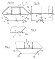
- the swap body 2 of FIG. 1 a and 1 b is constructed symmetrically with respect to the levels 4 and 6.
- the open at its top 8 swap body 2 has on its side walls in each case two suspension pins 10 for attachment of the chain harness of a skip loader vehicle.
- the swap body 2 has a respective cassette-like recess 16, which is located in the lower area in the container center.
- In each recess 16 is a horizontally extending and in the swap body fixed tilting bearing bolt 18.
- the in the positioning of the interchangeable container on the loading floor of a skip loader rear dump bolt 18 is engaged in the Kipp founded convinced the skip loader of a fishing hook, so that the swap body 2 are tilted about a defined by the tilting bearing pin 18 tilting axis can.
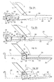
- FIGS. 1a and 2b the front lower portion of a swap body 2 of the type shown in FIGS. 1a and 2b is shown in longitudinal section on a loading floor of a freight transport tipping vehicle indicated at 20 whose sectional plane is aligned with the symmetry plane 6 shown in FIG essentially coincides.
- Fig. 2a shows the swap body 2 in normal driving position on the loading floor 20, wherein the forwardly positioned in the direction of travel tilting bearing pin 18 can be seen as the element to be engaged by the load securing device.
- the load securing device comprises a linearly along a guide, indicated schematically at 22, between an unlocking position (see FIGS. 2 a and 2b) and a locking position (see FIGS.
- FIG. 2c and 2d in the vehicle longitudinal direction, which can be displaced in the vehicle longitudinal direction with a locking claw 25 or A locking jaw 26.
- the locking jaw 26 is shown in FIG. 2a to the vehicle rear side open and positioned so that it retracts the locking element 24 from the position shown in FIG. 2a in the position shown in FIG. 2c the tilting bearing pin 18 engages.
- the locking element 24 is displaceable by means of a hydraulic drive device along the horizontal guide 22.
- the drive means comprises a hydraulic cylinder 28 which at 30 on the load transport vehicle is arranged pivotably about a horizontal pivot axis.
- At the piston rod end 32 of the cylinder 28 is pivotally connected to a pivot lever 34.
- the arranged on the locking element 24 pivot lever 34 is pivotable between the stop position shown in FIG. 2a and the stop position shown in FIG. 2b by partially extending and retracting the piston rod 36, namely about the hinge axes 30 and 37 parallel horizontal pivot axis 38th Soll
- the container 2 are locked out of the situation shown in FIG. 2a on the loading floor 20, the drive means is activated to retract the piston rod 36 into the cylinder tube 40 of the hydraulic cylinder 28.
- the pivot lever 34 passes from the first stop position shown in FIG. 2a in the second stop position shown in FIG. 2b.
- the stop positions are defined by the stops 42 and 44 on the locking element 24.
- the pivoting lever 34 rests against the stop 42 (FIG. 2a), whereas in the second pivoting position it bears against the stop 44 (see FIG. 2b).
- a securing pawl 46 is pivotally mounted about the horizontal axis 48.
- the safety pawl 46 is shown in a first latch position relative to the pivot lever 34, which is a preferred position to which the safety latch 46 is resiliently biased.
- the spring biasing mechanism is not shown in the figures.
- the locking pawl 46 closes the locking jaw 26 when the pivot lever 34 is in its second stop position.
- the safety latch 46 rests with its free end against the upper inner surface of the locking jaw 26 so that it can not be pivoted outwardly about the axis 48.
- the piston rod 36 is now drawn further into the cylinder tube 40, starting from the situation according to FIG. 2 b, in its orientation which is essentially parallel to the guide 22, it pulls the locking element 24 in the direction of the tilting bearing bolt 18.
- the securing pawl 46 thus comes with the tilting bearing pin 18 in contact and is displaced by this in a second pawl position, as indicated in Fig. 2b at 50 with dashed lines.
- the locking pawl 46 can snap back into the closed position, so that the tilting bearing pin 18 is surrounded in the manner shown in Fig. 2c on its entire circumference of parts of the locking element 24 and thus secured on all sides , In Fig. 2c, the swap body 2 is thus secured on the loading floor 22 against slipping.
- the drive means is to be activated so that the piston rod 36 is extended again from the cylinder tube 40 of the hydraulic cylinder 28.
- the pivot lever 34 is transferred from the second stop position out into the first stop position.
- the locking element 24 is then pushed starting from the situation shown in FIG. 2d in the vehicle longitudinal direction forward until it has again assumed the position shown in FIG. 2a.
- the swap body 2 can then be unloaded with a lifting device of the load transport vehicle or possibly placed in the tilting mode in tilted position.
- Fig. 1 b at B is a width dimension for the width of the locking jaw 26 of the locking element 24 of Figs. 2a - 2d drawn as an example.
- FIGS. 2a-2d can be varied in many ways.
- it is possible to guide the locking element 24 so that it is completely immersed in the unlocked position below the loading floor.
- an electrical spindle drive could be provided as a drive means for the locking element.
- the load securing device can be used to move the container 2 on the loading floor 20 within a certain tolerance in order to bring it into a predetermined position.
- the maximum stroke or displacement of the locking element may well be dimensioned so that it e.g. up to 1000 mm in order to be able to secure containers of different sizes.
- the load securing device according to the invention also works with interchangeable containers, in which a respective tilting bearing pin 18a is arranged in the manner shown in Fig. 3 outside with distance from the end wall 14.
- Fig. 4 shows a non-symmetrical swap body 2, in which originally only one tilting bearing pin 18 was provided, on the end side 14, which is to be positioned on receiving the interchangeable container 2 on the back of the vehicle.
- the container 2 in FIG. 4 was provided with a "dummy tilting bearing pin" 18a on the front side 12 , The element 18a thus serves for locking purposes on the vehicle.
- monitoring means may be provided which indicate or detect the locking state of a swap body on the loading floor.
- FIGS. 5 to 10 show diagrammatically and schematically further examples of possibilities for locking a replaceable container 2 on its tilting bearing bolt 18 according to the invention. Elements in FIGS. 5 to 10, which correspond to objects or elements of their operation in FIGS. 2 a to 2 d, are identified by the same reference numerals.
- the container 2 it is possible to secure the container 2 to both tilting bearing bolts 18 with a locking element 24.
- the locking element does not have a locking pawl of the type shown in Figures 2a-2d.
- a separate hydraulic cylinder 28 is shown in Figure 5 for each locking element, in an alternative embodiment the locking elements 24 could be coupled via a linkage or the like. Coupled, which allows the drive of the locking elements 24 with only a single drive cylinder 28.
- the cargo securing device of Fig. 5 is e.g. suitable for a tilting frame, which allows the tilting of the loading floor.
- a very advantageous feature in Fig. 5 is the inclined surface 25 on the upper inner side of the respective locking jaw 26. It extends from the inlet side of the locking jaw 26 forth from above to the base 31 of the locking jaw 26 down obliquely down so that they at horizontal approach of the Locking element 24 to the swap body 2, the tilting bearing pin 18 can apply low voltage. It can also be provided in the example according to FIG. 5 that the locking elements 24 are articulated to their drive elements 28 by means of a thrust rotary connection, so that they can be pivoted below the level of the loading floor surface during the transition into the unlocking position (see arrow 33). ,
- a hinge system 27 is interposed between the drive cylinder 28 and the hook-shaped locking element 24, which allows a pivotal movement S and a vertical movement V of the locking element 24 by actuation of the cylinder 28, wherein the locking element 24 as from above on the Kipplagerbolzen 18 pressing retaining element can be effective.
- a hook element pivotable about the axis X is provided as the locking element 24 for engaging the tilting bearing bolt 18.
- both tilting bearing bolts 18 of the interchangeable container 2 can be interlockingly engaged.
- FIG. 7 a shows a variant of the embodiment according to FIG. 7, in which the pivotable locking element 24 engages the tilting bearing bolt 18 from the container side.
- a movable locking element 24 is provided for a tilting bearing bolt 18 and a locking element 24b fixed relative to the loading floor for the other tilting bearing bolt 18.
- the locking element 24 is both pivotable to submerge it as needed below the loading floor level, and horizontally translationally displaced to move the swap body 2 as needed so that the rigid locking element 24 b the relevant tilting bearing pin 18 can engage.
- FIG. 9 is a modification of the example of FIG. 8 in so far as instead of the locking jaw 24 b a stop block 24 c is provided in Fig. 9, against which the tilting bearing pin 18 upon displacement of the interchangeable container 2 by movement of the locking element 24 strikes.
- FIG. 10 shows an embodiment which has two stop blocks 24c, 24c 'as locking elements on the loading floor.
- these stop blocks are rigidly fixed. Their distance from each other is chosen so that they can safely pick up a swap body 2 in the manner outlined and thereby secure to the tilting bearing pin 18 against slipping.
- the locking pads 24c, 24c ' have obliquely downwardly extending Einweis lake 60 for the container 2. These Einweis vom 60 lead the container 2 when placed on the loading floor in the correct position shown in FIG. 10.
- the embodiment of FIG. 10 is accessible to modifications, so it can be provided that at least one of the two locking pads 24c, 24c 'is deflectable against a restoring spring force, as indicated by the arrow Y.
- All embodiments of the invention have in common that locking means are provided which serve to secure a swap container on one or more tilting bearing bolts on the loading floor of the load transport vehicle against slipping.
- swap bodies have on one or possibly on both sides two or more tilting bearing bolts, which are each taken in the Kipp istsart of its own fishing hook in engagement. It is within the scope of the invention of course conceivable that in such a case, a plurality of locking elements may be provided in a load transport vehicle according to the invention in order to lock these multiple Kipplagerbolzen and / or take hold down.
Abstract
Description
Die Erfindung betrifft ein Lastentransportfahrzeug, insbesondere Absetzkipper, mit einem Ladeboden als Unterlage für einen mittels einer Hubvorrichtung auf den Ladeboden aufzusetzenden bzw. von dem Ladeboden abzuhebenden Absetzkipper-Wechselbehälter, der in seinem unteren Bereich vorn und hinten einen jeweiligen Kipplagerbolzen aufweist, und mit einer Ladungssicherungseinrichtung zur Sicherung eines Wechselbehälters gegen Verrutschen auf dem Ladeboden.The invention relates to a load transport vehicle, in particular skip loader, with a loading floor as a support for a aufsetzten by means of a lifting device on the loading floor or lifted from the loading floor skip loader swap body having in its lower region front and rear a respective tilting bearing bolt, and with a load securing device to secure a swap body against slipping on the loading floor.
Absetzkipperfahrzeuge werden für den Transport von Wechselbehältern eingesetzt. Bekannte Absetzkipper sind mit hydraulischen Hubvorrichtungen ausgestattet, um Wechselbehälter über das Fahrzeugheck hinweg auf- und abzuladen. Die Hubvorrichtung weist zwei im Wesentlichen parallel zueinander angeordnete und um eine im Heckbereich des Kipperfahrzeugs quer zur Fahrzeuglängsrichtung verlaufende Schwenkachse schwenkbare Hubarme auf, welche so voneinander beabstandet sind, dass sie einen Wechselbehälter zwischen sich aufnehmen können. Jeder der beiden Hubarme weist an seinem freien Ende ein Kettengeschirr zum Anhängen eines Wechselbehälters auf. Als Schwenkantrieb für die Hubarme sind Hydraulikzylinder vorgesehen. Durch Verschwenken der Hubarme kann ein daran angehängter Wechselbehälter über das Heck des Abssetzkipperfahrzeugs hinweg aufgeladen bzw. abgeladen werden.Dump trucks are used for the transport of swap bodies. Known skip loaders are equipped with hydraulic lifting devices to load and unload swap bodies across the rear of the vehicle. The lifting device has two substantially parallel to each other and about a pivotable in the rear region of the dump truck transversely to the vehicle longitudinal direction pivot axis lifting arms, which are spaced apart so that they can accommodate a swap body between them. Each of the two lifting arms has at its free end a chain harness for attaching a swap body. As a rotary actuator for the lifting arms hydraulic cylinders are provided. By pivoting the lift arms, a swap body attached thereto can be charged or unloaded across the rear of the dump truck.
In einer Kippbetriebsart kann ein Wechselbehälter am Fahrzeug in eine Kippstellung gebracht werden, um Schüttgut oder dgl. über das Fahrzeugheck hinweg auszukippen. Hierzu wird der zunächst auf dem Ladeboden des Absetzkipperfahrzeugs aufstehende Wechselbehälter durch Verschwenken der Hubarme in Richtung Heck nach hinten verlagert, wobei ein in Fangbereitschaftsstellung gebrachter Fänghaken am Fahrzeugheck mit einem Kipplagerbolzen am hinten liegenden Ende des Wechselbehälters in Eingriff kommt. Fanghaken und Kipplagerbolzen funktionieren dann als Kipperlager, wobei sie die Bewegungsfreiheitsgrade des Wechselbehälters auf einen Kippfreiheitsgrad beschränken. Der Wechselbehälter gerät bei Fortsetzung der Schwenkbewegung der Hubarme in Kippstellung, so dass etwaige Ladung über das Fahrzeugheck hinweg nach hinten ausgekippt werden kann. Durch Umkehrung der Schwenkbewegung der Hubarme kann danach der Wechselbehälter wieder auf den Ladeboden des Absetzkipperfahrzeugs aufgesetzt werden.In a Kippbetriebsart a swap body can be brought to the vehicle in a tilted position to dump bulk or the like. Over the rear of the vehicle. For this purpose, the initially on the loading floor of Absetzkipperfahrzeugs upstanding swap body is displaced by pivoting the lifting arms in the direction of the rear to the rear, with a brought in catch position catching hook at the rear of the vehicle with a tilting bearing pin at the rear end of the swap body into engagement comes. Catch hooks and tilting bearing bolts then function as dumpers, restricting the degrees of freedom of movement of the interchangeable container to a tilting degree of freedom. The swap body gets in continuation of the pivoting movement of the lifting arms in tilted position, so that any charge can be dumped over the rear of the vehicle away to the rear. By reversing the pivoting movement of the lifting arms, the swap body can then be placed back onto the loading floor of the skip trailer vehicle.
Aus Sicherheitsgründen ist es erforderlich, den auf dem Ladeboden aufgesetzten Wechselbehälter mittels einer Ladungssicherungseinrichtung gegen Verrutschen zu sichern. Dies erfolgt bei bekannten Absetzkipperfahrzeugen mittels Behälteranschlagsklötzen, an denen der Wechselbehälter auf dem Ladeboden formschlüssig ansteht. Die Behälteranschlagsklötze sind üblicherweise verstellbar an dem Absetzkipperaufbau des Fahrzeugs angeordnet, wobei sie über die Ladebodenebene nach oben hin abstehen, um mit betreffenden Behälterseitenwänden in Anschlagsstellung kommen zu können. Die Einstellbarkeit dieser Behälteranschläge in Klotzform erlaubt eine Anpassung an unterschiedlich geformte bzw. unterschiedlich große Wechselbehälter. Es sind auch bereits Ladungssicherungseinrichtungen für Absetzkipperfahrzeuge bekannt geworden, bei denen die konventionellen Behälteranschläge mittels hydraulischer Antriebe verstellbar sind. Üblicherweise erfolgt die Ladungssicherung mittels solcher Behälteranschläge gegen Verrutschen des Behälters nach vorn und zu den beiden Lateralseiten. Entgegen der Fahrtrichtung können die korrekt eingestellten Tragketten den Behälter sichern.For safety reasons, it is necessary to secure the swap container mounted on the loading floor by means of a load securing device against slipping. This is done in known Absetzkipperfahrzeugen means Behälteranschlagsklötzen, where the interchangeable container is positively present on the loading floor. The Behälteranschlagsklötze are usually arranged adjustably on the Absetzkipperaufbau of the vehicle, wherein they protrude above the loading floor level upwards to come with relevant container side walls in stop position can. The adjustability of these container stops in block shape allows adaptation to differently shaped or different sized swap bodies. There are also already known load securing devices for skip loader vehicles, in which the conventional container stops are adjustable by means of hydraulic drives. Usually, the load securing takes place by means of such container stops against slipping of the container forward and to the two lateral sides. Contrary to the direction of travel, the correctly adjusted carrying chains can secure the container.
Es ist auch möglich, mit einem Absetzkipperfahrzeug einen Wechselbehälter vom Ladeboden des Fahrzeugs auf einen Anhänger zu transferieren. Bei einem solchen Anhänger sind ebenfalls Ladungssicherungsmaßnahmen zu treffen, um ein Verrutschen des Wechselbehälters zu verhindern.It is also possible to transfer a swap body from the loading floor of the vehicle to a trailer with a skip loader vehicle. In such a trailer load securing measures are also to be taken to prevent slipping of the swap body.
Bei bekannten Lastentransportfahrzeugen der hier betrachteten Art weist die Ladungssicherungseinrichtung jeweils mindestens zwei Behälteranschläge für jede Behälterseitenwand und zwei Behälteranschläge für die vordere Wand des Wechselbehälters auf. Es liegen somit mindestens sechs Behälteranschläge vor. Eine Ladungssicherungseinrichtung mit einer solch großen Anzahl an einstellbaren Behälteranschlagsklötzen ist aufwendig und hat bei Behälterwechsel einen großen Einstellbedarf, um den Behälter zuverlässig zu sichern.In known load transport vehicles of the type considered here has the Load securing device in each case at least two container stops for each container side wall and two container stops for the front wall of the interchangeable container on. There are thus at least six container stops. A load securing device with such a large number of adjustable Behälteranschlagsklötzen is expensive and has a large adjustment needs when changing containers to secure the container reliable.
Der Begriff Lastentransportfahrzeug wird hier sowohl zur Bezeichnung von Absetzkipperfahrzeugen im eigentlichen Sinne als auch zur Bezeichnung von Anhängern zum Transport von Absetzkipper-Wechselbehältern verwendet.The term load transport vehicle is used here both to designate skip loader vehicles in the true sense as well as to designate trailers for the transport of skip loader swap bodies.
Der vorliegenden Erfindung liegt die Aufgabe zugrunde, ein Lastentransportfahrzeug der eingangs genannten Art mit einer verbesserten Ladungssicherungseinrichtung bereitzustellen, welche zuverlässig funktioniert und mit einer geringeren Anzahl an Behälteranschlägen oder dgl. auskommt.The present invention has for its object to provide a load transport vehicle of the type mentioned with an improved load securing device, which works reliably and with a smaller number of container stops or the like.
Zur Lösung dieser Aufgabe wird erfindungsgemäß vorgeschlagen, dass bei einem Lastentransportfahrzeug der eingangs genannten Art die Ladungssicherungseinrichtung ein Verriegelungselement aufweist, welches relativ zum Ladeboden zwischen einer Verriegelungsstellung und einer Entriegelungsstellung in der Weise bewegbar an dem Lastentransportfahrzeug angeordnet ist, dass es beim Übergang von der Entriegelungsstellung in die Verriegelungsstellung einen Kipplagerbolzen eines auf dem Ladeboden in normaler Fahrtstellung positionierten Absetzkipper-Wechselbehälters verriegelnd in Eingriff nehmen kann, um den Absetzkipper-Wechselbehälter zu sichern.To solve this problem, the invention proposes that in a load transport vehicle of the type mentioned, the load securing device has a locking element which is arranged relative to the loading floor between a locking position and an unlocking in the manner movable on the load transport vehicle, that it is at the transition from the unlocking position in the latching position is adapted to interlockingly engage a dump bolt of a dump truck swap body positioned on the cargo floor in normal drive position to secure the dump truck swap body.
Das Verriegelungselement nimmt den Wechselbehälter in bevorzugter Weise so in Eingriff, dass es ihn nicht nur gegen Verrutschen in Fahrzeuglängsrichtung sichert, sondern auch in Richtung quer dazu, und zwar zu beiden Seiten. Dies erlaubt es, auf zumindest einige, wenn nicht gar alle Behälteranschläge, wie sie bei konventionellen Absetzkipperfahrzeugen vorgesehen sind, zu verzichten und somit die Ladungssicherungseinrichtung erheblich zu vereinfachen. Da bei dem Lastentransportfahrzeug nach der Erfindung das Verriegelungselement den Kipplagerbolzen des Wechselbehälters ggf. auch von oben übergreifen kann, ist der Wechselbehälter auch gegen Abhebebewegungen, etwa bei Fahrt des Lastentransportfahrzeugs auf unebener Fahrbahn gesichert. Bei bevorzugten Ausführungsformen der Erfindung dient das Verriegelungselement auch als Niederhalteelement, welches eine ggf. elastisch nachgiebige Niederhaltekraft auf den in Eingriff genommenen Kipplagerbolzen ausübt.The locking element engages the swap body in a preferred manner so that it not only secures against slipping in the vehicle longitudinal direction, but also in the direction transverse thereto, on both sides. This allows for at least some, if not all, of the container stops as provided by conventional skip loader vehicles are to dispense and thus greatly simplify the load securing device. Since in the load transport vehicle according to the invention, the locking element may overlap the tilting bearing bolts of the interchangeable container, if necessary, from above, the swap body is also secured against lifting movements, such as driving the load transport vehicle on uneven road. In preferred embodiments of the invention, the locking element also serves as a hold-down element which exerts an optionally elastically yielding hold-down force on the engaged tilting bearing bolt.
Vorzugsweise ist das Verriegelungselement im vorderen Bereich des Ladebodens installiert, so dass es den vorn positionierten Kipplagerbolzen eines in normaler Fahrtstellung auf dem Ladeboden befindlichen Absetzkipper-Wechselbehälters beim Übergang von der Entriegelungsstellung in die Verriegelungsstellung verriegelnd in Eingriff nehmen kann. Damit soll aber nicht ausgeschlossen sein, dass ein betreffendes Verriegelungselement im hinteren Bereich des Ladebodens für den hinten positionierten Kipplagerbolzen des Wechselbehälters vorgesehen ist. Ferner kann es in einer Ausführungsform der Erfindung vorgesehen sein, dass sowohl ein vorderes Verriegelungselement als auch ein hinteres Verriegelungselement vorgesehen ist, so dass beide Kipplagerbolzen eines Wechselbehälters verriegelnd in Eingriff genommen werden können. Es ist darauf hinzuweisen, dass es auch Wechselbehälter gibt, welche nur an einer Seite einen Kipplagerbolzen aufweisen, wobei dies dann die Seite ist, welche bei auf dem Lastentransportfahrzeug aufgenommenem Wechselbehälter normalerweise hinten positioniert ist. Bei solchen Behältern kann es zweckmäßig sein, eine Eingriffsmöglichkeit für das Verriegelungselement auch an der Behältervorderseite vorzusehen, so dass auch solche Behälter sicher mit einem das Verriegelungselement im vorderen Ladebodenbereich aufweisenden Lastentransportfahrzeug nach der Erfindung transportiert werden können. Das Verriegelungselement weist vorzugsweise eine Klaue auf, mit der es beim Übergang von der Entriegelungsstellung in die Verriegelungsstellung einen betreffenden Kipplagerbolzen eines in normaler Fahrtstellung auf dem Ladeboden befindlichen Absetzkipper-Wechselbehälters von außen übergreifen kann.Preferably, the locking element is installed in the front region of the loading floor, so that it can engage the front mounted tilting bearing bolts of a dump truck on the loading floor in the normal running position interlocking container during the transition from the unlocked position into the locking position. However, this should not be ruled out that a respective locking element is provided in the rear region of the loading floor for the rear-mounted tilting bearing bolt of the interchangeable container. Furthermore, it can be provided in one embodiment of the invention that both a front locking element and a rear locking element is provided so that both tilting bearing bolts of a swap body can be interlockingly engaged. It should be noted that there are also swap bodies which have only one side a tilting bearing bolt, which is then the side which is usually positioned in the back when taken on the load transport vehicle swap body. In such containers, it may be expedient to provide an intervention possibility for the locking element also on the front side of the container, so that even such containers can be safely transported with a locking element in the front cargo area having load transport vehicle according to the invention. The locking element preferably has a claw, with it at the transition from the unlocked position into the locking position a respective tilting bearing bolt located in a normal driving position on the loading floor Absetzkipper swap body can spread from the outside.
Vorzugsweise ist das Verriegelungselement zwischen der Verriegelungsstellung und der Entriegelungsstellung linear verschiebbar, insbesondere horizontal linear verschiebbar, an dem Lastentransportfahrzeug geführt.Preferably, the locking element between the locking position and the unlocking position is linearly displaceable, in particular horizontally linearly displaceable, guided on the load transport vehicle.
Die Ladungssicherungseinrichtung ist gemäß einer bevorzugten Variante der Erfindung mit einer Antriebseinrichtung für das Verriegelungselement ausgestattet, wobei es sich z.B. um eine hydraulische Antriebseinrichtung mit wenigstens einem hydraulischen Zylinder oder um eine elektrische Antriebseinrichtung mit Elektromotor und Spindeltrieb oder dgl. handeln kann.The load securing device is equipped according to a preferred variant of the invention with a drive device for the locking element, wherein it is e.g. can be a hydraulic drive device with at least one hydraulic cylinder or an electric drive device with electric motor and spindle drive or the like. Act.
Vorzugsweise ist das Verriegelungselement in eine inaktive Position unterhalb der Ladebodenebene bewegbar, so dass es keine Störkontur beim Aufsetzen eines Wechselbehälters auf den Ladeboden darstellt.Preferably, the locking element is movable to an inactive position below the loading floor level, so that it does not represent a disturbing contour when placing a swap body on the loading floor.
Vorzugsweise weist das Verriegelungselement ein Verriegelungsmaul auf, mit dem es beim Übergang von der Entriegelungsstellung in die Verriegelungsstellung einen betreffenden Kipplagerbolzen oder einen äquivalenten Eingriffsabschnitt eines in normaler Fahrtstellung auf dem Ladeboden befindlichen Absetzkipper-Wechselbehälters in Eingriff nehmen kann.Preferably, the locking element has a locking jaw, with which it can take a respective tilting bearing bolt or an equivalent engaging portion of a normal in the driving position on the loading floor dump truck swap body in the transition from the unlocked position into the locking position engage.
Gemäß einer bevorzugten Ausführungsform der Erfindung ist an dem Verriegelungselement eine Sicherungsklinke zum Öffnen und Schließen des Verriegelungsmaules angeordnet. Das Verriegelungsmaul kann somit einen darin aufgenommenen Kipplagerbolzen an dessen gesamtem Umfang umfassen, so dass der betreffende Wechselbehälter weder vor noch zurück in einem kritischen Maße rutschen kann und auch bei Fahrt über holpriger Straße gut an dem Ladeboden gesichert ist. Das Verriegelungsmaul sollte zweckmäßigerweise eine möglichst große Breite haben, so dass es einen Kipplagerbolzen auf einen großen Teil seiner Länge erfassen kann. Auf diese Weise ermöglicht die Ladungssicherungseinrichtung nach der Erfindung auch eine zuverlässige Sicherung eines Wechselbehälters gegen Verdrehen um eine vertikale Achse auf dem Ladeboden des Lastentransportfahrzeugs. Prinzipiell könnte ein einziges erfindungsgemäß ausgebildetes Verriegelungselement somit sämtliche Behälteranschlagsklötze eines Lastentransportfahrzeugs nach dem Stand der Technik ersetzen. Im Schwerlastbereich mag es jedoch aus Sicherheitsgründen angebracht sein, auch bei dem Lastentransportfahrzeug nach der Erfindung noch einige wenige Behälteranschläge konventioneller Art vorzusehen, insbesondere als Sicherung des Behälters gegen Verdrehen auf dem Ladeboden.According to a preferred embodiment of the invention, a securing pawl for opening and closing the locking muzzle is arranged on the locking element. The locking jaw can thus include a tilting bearing bolt received therein at its entire circumference, so that the swap body in question can neither slide back nor in a critical extent and is well secured to the loading floor even when driving over bumpy road. The locking jaw should expediently have the widest possible width, so that it can detect a tilting bearing pin on a large part of its length. In this way, the load securing device according to the invention also enables reliable securing of a swap body against rotation about a vertical axis on the loading floor of the load transport vehicle. In principle, a single locking element designed according to the invention could thus replace all container stop blocks of a load transport vehicle according to the prior art. In the heavy duty sector, however, it may be appropriate for safety reasons, even with the load transport vehicle according to the invention still provide a few container stops conventional type, especially as a backup of the container against rotation on the loading floor.
Bei der oben angesprochenen Ausführungsform der Erfindung mit Verriegelungsmaul und Sicherungsklinke wird eine Variante bevorzugt, bei der die Sicherungsklinke an einem Schwenkhebel angeordnet ist, der mittels der Antriebseinrichtung zwischen einer ersten Anschlagsstellung und einer zweiten Anschlagsstellung schwenkbar am Verriegelungselement angeordnet ist, derart, dass die Sicherungsklinke in eine das Verriegelungsmaul freigebende Öffnungsstellung übergeht, wenn der Schwenkhebel in die erste Anschlagsstellung gelangt, wohingegen die Sicherungsklinke in eine das Verriegelungsmaul schließende Schließstellung übergeht, wenn der Schwenkhebel in die zweite Anschlagsstellung gelangt. Es kann somit die Antriebseinrichtung, die zum Bewegen des Verriegelungselementes zwischen der Entriegelungsstellung und der Verriegelungsstellung vorgesehen ist, auch zum Verschwenken des Schwenkhebels mit der Sicherungsklinke und somit zum Öffnen und Schließen des Verriegelungsmauls genutzt werden.In the above-mentioned embodiment of the invention with locking jaw and securing pawl, a variant is preferred in which the securing pawl is arranged on a pivot lever, which is arranged by means of the drive means between a first stop position and a second stop position pivotally mounted on the locking element, such that the safety catch in an opening position releasing the locking jaw transitions when the pivoting lever reaches the first stop position, whereas the securing pawl merges into a closing position closing the locking jaw when the pivoting lever reaches the second stop position. It can thus be used to pivot the pivot lever with the safety latch and thus to open and close the locking jaw, the drive means which is provided for moving the locking element between the unlocked position and the locking position.
Die Sicherungsklinke ist gemäß einer weiteren Ausführungsform der Erfindung zwischen einer mit der Schließstellung korrespondierenden ersten Klinkenstellung und einer zweiten Klinkenstellung schwenkbar an dem Schwenkhebel angeordnet, derart, dass sie aus ihrer Schließstellung heraus unter Öffnung des Verriegelungsmauls zum Inneren des Verriegelungsmauls hin von einer in Bezug auf das Verriegelungsmaul von außen auf die Sicherungsklinke wirkenden Kraft in die zweite Klinkenstellung verdrängt werden kann, wenn sich der Schwenkhebel in seiner zweiten Schwenkstellung befindet. Diese Ausführungsform ermöglicht es, das Verriegelungselement bei geschlossenem Verriegelungsmaul an den Kipplagerbolzen eines ordnungsgemäß auf dem Ladeboden aufstehenden Wechselbehälters heranzuführen und die Sicherungsklinke dann unter der Wirkung des sie von außen beaufschlagenden Kipplagerbolzens bei weiterer Annäherung des Verriegelungselements an den Wechselbehälter zu verdrängen, so dass sie kurzzeitig in die das Verriegelungsmaul öffnende zweite Klinkenstellung übergeht, um den Kipplagerbolzen in das Verriegelungsmaul des Verriegelungselementes hineinzulassen. Danach kann die Sicherungsklinke in ihre mit der Schließstellung korrespondierende erste Klinkenstellung zurückgehen, so dass der Kipplagerbolzen nunmehr in dem Verriegelungsmaul gefangen ist. Vorzugsweise ist die Sicherungsklinke zu der ersten Klinkenstellung hin federnd vorgespannt, so dass sie nach Aufnahme eines Kipplagerbolzens in dem Verriegelungsmaul selbsttätig in die Schließstellung zurückschnappen kann.The securing pawl is arranged according to a further embodiment of the invention between a corresponding with the closed position first pawl position and a second pawl position pivotally mounted on the pivot lever, such that it from its closed position under opening of the locking jaw to the interior of the locking jaw out from a respect to the Locking jaw can be displaced from the outside on the safety catch force acting in the second pawl position when the pivot lever is in its second pivot position. This embodiment allows the locking element at closed locking jaw on the tilting bearing bolts of a duly standing on the loading floor swap body and then displace the safety pawl under the action of it acting on the outside of the rolling bearing bolt on further approximation of the locking element to the swap body so that it briefly passes into the locking mouth opening second pawl position, to let the tilting bearing bolt into the locking jaw of the locking element. Thereafter, the safety latch can go back to its corresponding with the closed position first latch position, so that the tilting bearing bolt is now trapped in the locking jaw. Preferably, the securing pawl is resiliently biased toward the first catch position, so that it can automatically snap back into the closed position after receiving a tilting bearing bolt in the locking mouth.
Ein sehr einfaches Getriebe zur Betätigung der Sicherungsklinke und zur Bewegung des Verriegelungselementes ist dadurch realisiert, dass der Schwenkhebel mit einem Zug-Schubgestänge der Antriebseinrichtung verbunden ist, derart, dass er durch Zug bzw. Schub des Zug-Schubgestänges zwischen den beiden Anschlagsstellungen verschwenkbar ist, wobei eine Fortsetzung der Schubbewegung bzw. Zugbewegung des Zug-Schubgestänges nach Einbringen des Schwenkhebels in die erste Anschlagsstellung zur Bewegung des Verriegelungselementes zur Entriegelungsstellung hin führt, wohingegen eine Fortsetzung der Schubbewegung bzw. Zugbewegung des Zug-Schubgestänges nach Einbringen des Schwenkhebels in die zweite Anschlagsstellung zur Bewegung des Verriegelungselementes zur Verriegelungsstellung hin führt. Das Zug-Schubgestänge kann z.B. eine Kolbenstange eines hydraulischen Zylinders umfassen oder von einer solchen gebildet sein, wobei in diesem Fall eine hydraulische Antriebsvorrichtung vorausgesetzt wurde. Im Falle eines elektrischen Antriebs kann das Zug-Schubgestänge z.B. eine Spindel eines Spindeltriebs umfassen oder von dieser gebildet sein. Der maximale Hub des Zug-Schubgestänges bzw. der maximale Verschiebeweg des Verriegelungselementes kann bedarfsweise lang dimensioniert sein, so dass entsprechend unterschiedlich große oder/und unterschiedlich auf dem Ladeboden positionierte Wechselbehälter gesichert werden können.A very simple transmission for actuating the securing pawl and for moving the locking element is realized in that the pivoting lever is connected to a train-pushrod of the drive device, such that it can be pivoted by train or thrust of the train pushrod between the two stop positions, wherein a continuation of the pushing movement or pulling movement of the train push rod leads after introduction of the pivot lever in the first stop position for movement of the locking element to the unlocking position, whereas a continuation of the pushing movement or pulling movement of the train push rod after introduction of the pivot lever in the second stop position for Movement of the locking element leads to the locking position out. The pull-push rod may include, for example, a piston rod of a hydraulic cylinder or be formed by such, in which case a hydraulic drive device has been assumed. In the case of an electric drive, the train-push rod may for example comprise a spindle of a spindle drive or be formed by this. The maximum stroke of the pull-push rod or the maximum displacement of the locking element can be required to be long dimensioned, so that correspondingly different sizes and / or differently positioned on the loading floor swap bodies can be secured.
Die Erfindung wird nachstehend unter Bezug auf die Zeichnungen näher erläutert.The invention will be explained in more detail below with reference to the drawings.
Darin zeigen
- die Fig. 1a und 1 b einen Absetzkipper-Wechselbehälter symmetrischer Bauart mit einem jeweiligen Kipplagerbolzen an beiden Längsendseiten in Seitenansicht und in Vorderansicht,
- Fig. 2a - 2d in schematischer Darstellung das Verriegelungselement mit zugehöriger Antriebseinrichtung in vier verschiedenen Einstellungen während der Verriegelung und anschließender Entriegelung eines Behälters nach den Fig. 1 a und 1 b auf dem Ladeboden eines Lastentransportfahrzeugs,
- Fig. 3 einen Ausschnitt eines Wechselbehälters in Seitenansicht mit einer Alternative der Anordnung eines Kipplagerbolzens und
- Fig. 4 einen weiteren Wechselbehälter, der zum gesicherten Transport mit einem Lastentransportfahrzeug nach der Erfindung geeignet ist.
- Fig. 5
bis 10 zeigen in skizzenhafter schematischer Darstellung weitere Varianten der erfindungsgemäßen Verriegelung eines Wechselbehälters.
- 1a and 1b a skip loader swap body of symmetrical design with a respective tilting bearing bolt on both longitudinal end sides in side view and in front view,
- 2a-2d show a schematic illustration of the locking element with associated drive device in four different settings during the locking and subsequent unlocking of a container according to FIGS. 1 a and 1 b on the loading floor of a freight transport vehicle,
- Fig. 3 shows a detail of a swap body in side view with an alternative arrangement of a tilting bearing bolt and
- Fig. 4 shows a further swap body, which is suitable for secure transport with a load transport vehicle according to the invention.
- Fig. 5 to 10 show in sketch-like schematic representation of further variants of the inventive locking a swap body.
Der Wechselbehälter 2 gemäß Fig. 1 a und 1 b ist in Bezug auf die Ebenen 4 und 6 symmetrisch aufgebaut. Der an seiner Oberseite 8 offene Wechselbehälter 2 hat an seinen Seitenwänden jeweils zwei Aufhängezapfen 10 zur Befestigung des Kettengeschirrs eines Absetzkipperfahrzeugs. An den Längsendseiten 12 und 14 weist der Wechselbehälter 2 eine jeweilige kassettenartige Ausnehmung 16 auf, die sich im unteren Bereich in Behältermitte befindet. In jeder Ausnehmung 16 befindet sich ein horizontal verlaufender und am Wechselbehälter fixierter Kipplagerbolzen 18. Der in der Positionierung des Wechselbehälters auf dem Ladeboden eines Absetzkippers hinten liegende Kipplagerbolzen 18 wird in der Kippbetriebsart des Absetzkippers von einem Fanghaken in Eingriff genommen, so dass der Wechselbehälter 2 um eine von dem Kipplagerbolzen 18 definierte Kippachse gekippt werden kann.The
In der Absetzstellung eines Wechselbehälters 2 auf dem Ladeboden eines Absetzkippers hatten die Kipplagerbolzen 18 bisher keine Funktion. Dies ändert sich nun bei der Realisierung der vorliegenden Erfindung, wie dies anhand der Fig. 2a - 2d im Folgenden erläutert wird.In the set-down position of a
In den Fig. 2a - 2d ist der vordere untere Bereich eines Wechselbehälters 2 der in den Fig. 1a und 2b gezeigten Bauart auf einem bei 20 angedeuteten Ladeboden eines Lastentransportkipperfahrzeugs in einer Längsschnittdarstellung gezeigt, deren Schnittebene mit der in Fig. 1 b eingezeichneten Symmetrieebene 6 im Wesentlichen übereinstimmt. Fig. 2a zeigt den Wechselbehälter 2 in normaler Fahrtstellung auf dem Ladeboden 20, wobei der in Fahrtrichtung vorne positionierte Kipplagerbolzen 18 als das von der Ladungssicherungseinrichtung in Eingriff zu nehmende Element erkennbar ist. Die Ladungssicherungseinrichtung umfasst ein linear längs einer bei 22 schematisch angedeuteten Führung zwischen einer Entriegelungsstellung (vgl. Fig. 2a und Fig. 2b) und einer Verriegelungsstellung (vgl. Fig. 2c und Fig. 2d) in Fahrzeuglängsrichtung verschiebbares Verriegelungselement 24 mit einer Verriegelungsklaue 25 bzw. einem Verriegelungsmaul 26. Das Verriegelungsmaul 26 ist gemäß Fig. 2a zur Fahrzeugrückseite hin offen und so positioniert, dass es beim Zurückziehen des Verriegelungselementes 24 von der Stellung gemäß Fig. 2a in die Stellung gemäß Fig. 2c den Kipplagerbolzen 18 in Eingriff nimmt.2a-2d, the front lower portion of a
Das Verriegelungselement 24 ist mittels einer hydraulischen Antriebseinrichtung längs der Horizontalführung 22 verschiebbar. Die Antriebseinrichtung umfasst einen Hydraulikzylinder 28, der bei 30 an dem Lastentransportfahrzeug um eine horizontale Schwenkachse schwenkbar angeordnet ist. An dem kolbenstangenseitigen Ende 32 ist der Zylinder 28 mit einem Schwenkhebel 34 gelenkig verbunden. Der an dem Verriegelungselement 24 angeordnete Schwenkhebel 34 ist zwischen der Anschlagstellung gemäß Fig. 2a und der Anschlagsstellung gemäß Fig. 2b durch partielles Ein- und Ausfahren der Kolbenstange 36 verschwenkbar, und zwar um die zu den Gelenkachsen 30 und 37 parallele horizontale Schwenkachse 38. Soll nun der Behälter 2 aus der Situation gemäß Fig. 2a heraus auf dem Ladeboden 20 verriegelt werden, so wird die Antriebseinrichtung aktiviert, um die Kolbenstange 36 ins Zylinderrohr 40 des hydraulischen Zylinders 28 einzuziehen. Dabei gelangt zunächst der Schwenkhebel 34 von der ersten Anschlagsstellung gemäß Fig. 2a in die zweite Anschlagsstellung gemäß Fig. 2b. Die Anschlagsstellungen sind durch die Anschläge 42 und 44 an dem Verriegelungselement 24 definiert. In der ersten Anschlagsstellung liegt der Schwenkhebel 34 an dem Anschlag 42 an (Fig. 2a), wohingegen er in der zweiten Schwenkstellung an dem Anschlag 44 anliegt (vgl. Fig. 2b).The locking
An dem Schwenkhebel 34 ist eine Sicherungsklinke 46 um die horizontale Achse 48 schwenkbar angeordnet. In den Fig. 2a - 2d ist die Sicherungsklinke 46 in einer ersten Klinkenstellung relativ zu dem Schwenkhebel 34 dargestellt, wobei es sich um eine Vorzugsstellung handelt, zu der die Sicherungsklinke 46 federnd vorgespannt ist. Der Federvorspannmechanismus ist in den Figuren nicht gezeigt. Wie aus den Fig. 2b und 2c zu erkennen ist, verschließt die Sicherungsklinke 46 das Verriegelungsmaul 26, wenn der Schwenkhebel 34 in seiner zweiten Anschlagsstellung ist. Die Sicherungsklinke 46 liegt dabei mit ihrem freien Ende so an der oberen Innenfläche des Verriegelungsmauls 26 an, dass sie nicht nach außen um die Achse 48 verschwenkt werden kann.On the
Wird die Kolbenstange 36 nun ausgehend von der Situation gemäß Fig. 2b weiter in das Zylinderrohr 40 eingezogen, so zieht sie in ihrer im Wesentlichen zur Führung 22 parallelen Ausrichtung das Verriegelungselement 24 in Richtung zu dem Kipplagerbolzen 18. Dabei kommt die Sicherungsklinke 46 mit dem Kipplagerbolzen 18 in Kontakt und wird von diesem in eine zweite Klinkenstellung verdrängt, wie dies in Fig. 2b bei 50 mit gestrichelten Linien angedeutet ist. Sobald der Kipplagerbolzen 18 weit genug in dem Verriegelungsmaul 26 aufgenommen ist, kann die Sicherungsklinke 46 in die Schließstellung zurückschnappen, so dass der Kipplagerbolzen 18 in der in Fig. 2c gezeigten Weise an seinem gesamten Umfang von Teilen des Verriegelungselementes 24 umgeben und somit allseitig gesichert ist. In Fig. 2c ist somit der Wechselbehälter 2 auf dem Ladeboden 22 gegen Verrutschen gesichert.If the
Soll nun der Wechselbehälter aus der Situation gemäß Fig. 2c heraus wieder freigegeben werden, so ist die Antriebseinrichtung zu aktivieren, damit die Kolbenstange 36 wieder aus dem Zylinderrohr 40 des hydraulischen Zylinders 28 ausgefahren wird. Dabei wird zunächst der Schwenkhebel 34 aus der zweiten Anschlagsstellung heraus in die erste Anschlagsstellung überführt. Bei weiterem Herausschieben der Kolbenstange 36 aus dem Zylinderrohr 40 wird dann das Verriegelungselement 24 ausgehend von der Situation gemäß Fig. 2d in Fahrzeuglängsrichtung nach vorn geschoben, bis es wieder die Stellung gemäß Fig. 2a eingenommen hat. Der Wechselbehälter 2 kann dann mit einem Hubgerät des Lastentransportfahrzeugs abgeladen oder ggf. in der Kippbetriebsart in Kippstellung gebracht werden.If now the swap body from the situation shown in FIG. 2c out again be released, the drive means is to be activated so that the
In Fig. 1 b ist bei B ein Breitenmaß für die Breite des Verriegelungsmauls 26 des Verriegelungselementes 24 aus den Fig. 2a - 2d als Beispiel eingezeichnet.In Fig. 1 b at B is a width dimension for the width of the locking
Das Ausführungsbeispiel der Erfindung gemäß den Fig. 2a - 2d kann in vielfältiger Weise variiert werden. So besteht die Möglichkeit, das Verriegelungselement 24 so zu führen, dass es in der Entriegelungsstellung vollständig unterhalb des Ladebodens abtaucht.The embodiment of the invention according to FIGS. 2a-2d can be varied in many ways. Thus, it is possible to guide the locking
Anstelle eines oder mehrerer Hydraulikzylinder könnte ein elektrischer Spindeltrieb als Antriebsmittel für das Verriegelungselement vorgesehen sein.Instead of one or more hydraulic cylinders, an electrical spindle drive could be provided as a drive means for the locking element.
Nachzutragen ist noch, dass bei entsprechender Dimensionierung die Ladungssicherungseinrichtung nach der Erfindung dazu benutzt werden kann, den Behälter 2 auf dem Ladeboden 20 im Rahmen einer bestimmten Toleranz zu verschieben, um ihn in eine vorbestimmte Position zu bringen. Der maximale Hub bzw. Verschiebeweg des Verriegelungselementes kann durchaus so dimensioniert sein, dass er z.B. bis zu 1000 mm beträgt, um unterschiedlich große Behälter sichern zu können.It should be added that with appropriate dimensioning the load securing device according to the invention can be used to move the
Die Ladungssicherungseinrichtung nach der Erfindung funktioniert auch mit Wechselbehältern, bei denen ein betreffender Kipplagerbolzen 18a in der in Fig. 3 gezeigten Weise außen mit Abstand von der Endwand 14 angeordnet ist.The load securing device according to the invention also works with interchangeable containers, in which a respective
Fig. 4 zeigt einen nicht symmetrischen Wechselbehälter 2, bei dem ursprünglich nur ein Kipplagerbolzen 18 vorgesehen war, und zwar an der Endseite 14, die bei Aufnahme des Wechselbehälters 2 auf den Ladeboden des Fahrzeugs hinten zu positionieren ist. Damit aber auch ein solcher Behälter 2 gemäß Fig. 4 mit einer vorderen Ladungssicherungseinrichtung gemäß den Fig. 2a - 2d auf dem Lastentransportfahrzeug zu sichern ist, wurde der Behälter 2 in Fig. 4 mit einem "Dummy-Kipplagerbolzen" 18a an der Vorderseite 12 versehen. Das Element 18a dient somit zu Verriegelungszwecken auf dem Fahrzeug.Fig. 4 shows a
Anzumerken ist auch noch, dass im Rahmen der Erfindung Sicherheitsmaßnahmen betreffend den Betrieb der Hubvorrichtung des Absetzkippers in Abhängigkeit vom Zustand der Ladungssicherungseinrichtung getroffen sind. So ist es gemäß einer Variante der Erfindung vorgesehen, dass eine Schwenkbewegung der Hubarme eines als Absetzkipper ausgebildeten Lastentransportfahrzeugs automatisch unterbunden wird, solange das Verriegelungselement der Ladungssicherungseinrichtung im Behälterverriegelungszustand ist.It should also be noted that in the context of the invention, safety measures have been taken concerning the operation of the lifting device of the skip loader in dependence on the state of the load securing device. Thus, it is provided according to a variant of the invention that a pivoting movement of the lifting arms of a dump truck designed as a load transport vehicle is automatically prevented, as long as the locking element of the load securing device is in the container locked state.
Ferner können Überwachungsmittel vorgesehen sein, die den Verriegelungszustand eines Wechselbehälters auf dem Ladeboden anzeigen bzw. detektieren.Furthermore, monitoring means may be provided which indicate or detect the locking state of a swap body on the loading floor.
In den Fig. 5 - 10 sind skizzenhaft und schematisch weitere Beispiele für Möglichkeiten der Verriegelung eines Wechselbehälters 2 an dessen Kipplagerbolzen 18 nach der Erfindung gezeigt. Elemente in den Figuren 5 - 10, die gegenständlich oder von ihrer Wirkungsweise Elementen in den Fig. 2a - 2d im Wesentlichen entsprechen, sind mit jeweils gleichen Bezugszeichen gekennzeichnet.FIGS. 5 to 10 show diagrammatically and schematically further examples of possibilities for locking a
Bei dem besonders bevorzugten Beispiel, der Fig. 5 besteht die Möglichkeit, den Behälter 2 an beiden Kipplagerbolzen 18 mit einem Verriegelungselement 24 zu sichern. Bei dem Beispiel der Fig. 5 hat das Verriegelungselement keine Sicherungsklinke der in den Fig. 2a - 2d gezeigten Art. Wenngleich in Fig. 5 für jedes Verriegelungselement ein eigener Hydraulikzylinder 28 dargestellt ist, so könnten in einer alternativen Ausführungsform die Verriegelungselemente 24 über ein Koppelgetriebe oder dgl. gekoppelt sein, welches den Antrieb der Verriegelungselemente 24 mit nur einem einzigen Antriebszylinder 28 ermöglicht. Die Ladungssicherungseinrichtung nach Fig. 5 ist z.B. für einen Kipprahmen geeignet, welcher das Kippen des Ladebodens ermöglicht.In the particularly preferred example of FIG. 5, it is possible to secure the
Ein sehr vorteilhaftes Merkmal in Fig. 5 ist die Schrägfläche 25 an der oberen Innenseite des jeweiligen Verriegelungsmauls 26. Sie verläuft von der Eintrittsseite des Verriegelungsmauls 26 her von oben zum Grund 31 des Verriegelungsmauls 26 hin schräg nach unten, so dass sie bei horizontaler Annäherung des Verriegelungselementes 24 an den Wechselbehälter 2 den Kipplagerbolzen 18 niederspannend beaufschlagen kann. Es kann auch bei dem Beispiel gemäß Fig. 5 vorgesehen sein, dass die Verriegelungselemente 24 vermittels einer Schub-Drehverbindung an ihre Antriebselemente 28 angelenkt sind, so dass sie beim Übergang in die Entriegelungsstellung unter das Niveau der Ladebodenfläche verschwenkbar sind (vgl. Pfeil 33).A very advantageous feature in Fig. 5 is the
Bei dem Beispiel nach Fig. 6 ist zwischen dem Antriebszylinder 28 und dem hakenförmigen Verriegelungselement 24 ein Gelenksystem 27 zwischengeschaltet, welches eine Schwenkbewegung S und eine Vertikalbewegung V des Verriegelungselementes 24 durch Betätigung des Zylinders 28 ermöglicht, wobei das Verriegelungselement 24 als von oben auf den Kipplagerbolzen 18 drückendes Niederhalteelement wirksam werden kann.In the example of Fig. 6, a
Bei dem Beispiel gemäß Fig. 7 ist als Verriegelungselement 24 ein um die Achse X verschwenkbares Hakenelement zur lneingriffnahme des Kipplagerbolzens 18 vorgesehen. Im Beispielsfall der Fig. 7 können beide Kipplagerbolzen 18 des Wechselbehälters 2 verriegelnd in Eingriff genommen werden.In the example according to FIG. 7, a hook element pivotable about the axis X is provided as the locking
Fig. 7a zeigt eine Variante des Ausführungsbeispiels nach Fig. 7, bei der das schwenkbare Verriegelungselement 24 den Kipplagerbolzen 18 von der Behälterseite her in Eingriff nimmt.FIG. 7 a shows a variant of the embodiment according to FIG. 7, in which the
Fig. 8 zeigt eine Variante, bei der ein bewegbares Verriegelungselement 24 für einen Kipplagerbolzen 18 und ein relativ zum Ladeboden fixiertes Verriegelungselement 24b für den anderen Kipplagerbolzen 18 vorgesehen ist. Als spezielle Variante dieses Konzepts mit einer starren und einer beweglichen Verriegelungsanordnung ist das Verriegelungselement 24 sowohl verschwenkbar, um es bedarfsweise unterhalb der Ladebodenebene abtauchen zu lassen, und horizontal translatorisch verschiebbar, um den Wechselbehälter 2 bei Bedarf so zu verschieben, dass das starre Verriegelungselement 24b den betreffenden Kipplagerbolzen 18 in Eingriff nehmen kann.8 shows a variant in which a
Bei dem Beispiel gemäß Fig. 9 handelt es sich um eine Abwandlung des Beispiels aus Fig. 8 insoweit, als anstelle des Verriegelungsmauls 24b ein Anschlagklotz 24c in Fig. 9 vorgesehen ist, gegen den der Kipplagerbolzen 18 bei Verschiebung des Wechselbehälters 2 durch Bewegung des Verriegelungselementes 24 anschlägt.In the example of FIG. 9 is a modification of the example of FIG. 8 in so far as instead of the locking
Fig. 10 zeigt eine Ausführungsform, welche zwei Anschlagsklötze 24c, 24c' als Verriegelungselemente an dem Ladeboden aufweist. In einer einfachen Variante der Erfindung sind diese Anschlagsklötze starr fixiert. Ihr Abstand voneinander ist so gewählt, dass sie einen Wechselbehälter 2 in der skizzierten Weise sicher aufnehmen können und dabei an den Kipplagerbolzen 18 gegen Verrutschen sichern. Die Verriegelungsklötze 24c, 24c' haben schräg nach unten verlaufende Einweisflächen 60 für den Behälter 2. Diese Einweisflächen 60 führen den Behälter 2 beim Aufsetzen auf den Ladeboden in die korrekte Stellung gemäß Fig. 10. Die Ausführungsform gemäß Fig. 10 ist Abwandlungen zugänglich, so kann es vorgesehen sein, dass wenigstens einer der beiden Verriegelungsklötze 24c, 24c' gegen eine rückstellende Federkraft auslenkbar ist, wie dies durch den Pfeil Y angedeutet ist.10 shows an embodiment which has two
Sämtliche Ausführungsformen der Erfindung haben gemeinsam, dass Verriegelungsmittel bereitgestellt werden, welche dazu dienen, einen Wechselbehälter an einem oder mehreren Kipplagerbolzen auf dem Ladeboden des Lastentransportfahrzeugs gegen Verrutschen zu sichern.All embodiments of the invention have in common that locking means are provided which serve to secure a swap container on one or more tilting bearing bolts on the loading floor of the load transport vehicle against slipping.
Es besteht die Möglichkeit, dass Wechselbehälter an einer oder ggf. an beiden Seiten zwei oder mehrere Kipplagerbolzen aufweisen, welche in der Kippbetriebsart jeweils von einem eigenen Fanghaken in Eingriff genommen werden. Es ist im Rahmen der Erfindung selbstverständlich denkbar, dass in einem solchen Fall auch mehrere Verriegelungselemente bei einem Lastentransportfahrzeug nach der Erfindung vorgesehen sein können, um diese mehrfachen Kipplagerbolzen verriegelnd oder/und niederhaltend in Eingriff zu nehmen.There is the possibility that swap bodies have on one or possibly on both sides two or more tilting bearing bolts, which are each taken in the Kippbetriebsart of its own fishing hook in engagement. It is within the scope of the invention of course conceivable that in such a case, a plurality of locking elements may be provided in a load transport vehicle according to the invention in order to lock these multiple Kipplagerbolzen and / or take hold down.
Claims (20)
dadurch gekennzeichnet,
dass die Ladungssicherungseinrichtung ein Verriegelungselement (24) aufweist, welches relativ zum Ladeboden (20) zwischen einer Verriegelungsstellung und einer Entriegelungsstellung in der Weise bewegbar an dem Lastentransportfahrzeug angeordnet ist, dass es beim Übergang von der Entriegelungsstellung in die Verriegelungsstellung einen Kipplagerbolzen (18) eines auf dem Ladeboden (20) in normaler Fahrtstellung positionierten Absetzkipper-Wechselbehälters (2) verriegelnd in Eingriff nehmen kann, um den Absetzkipper-Wechselbehälter (2) zu sichern.Load transport vehicle, in particular skip loader, with a loading floor (20) as a base for a aufsetzten by means of a lifting device on the loading floor or lifted from the loading floor skip loader swap body (2), the front and rear has a respective tilting bearing pin (18) in its lower region , and with a load securing device for securing a swap body (2) against slipping on the loading floor (20),
characterized,
in that the load securing device has a locking element (24), which is arranged relative to the loading floor (20) between a locking position and an unlocking in the manner movable on the load transport vehicle, that when passing from the unlocked position into the locking position a tilting bearing bolt (18) one on can interlockingly engage the skip (20) positioned in the normal running position to secure the skip loader swap body (2).
Applications Claiming Priority (1)
| Application Number | Priority Date | Filing Date | Title |
|---|---|---|---|
| DE102004057179A DE102004057179A1 (en) | 2004-11-26 | 2004-11-26 | Load transport vehicle, in particular skiploader |
Publications (3)
| Publication Number | Publication Date |
|---|---|
| EP1661755A2 true EP1661755A2 (en) | 2006-05-31 |
| EP1661755A3 EP1661755A3 (en) | 2007-06-13 |
| EP1661755B1 EP1661755B1 (en) | 2010-01-27 |
Family
ID=35911173
Family Applications (1)
| Application Number | Title | Priority Date | Filing Date |
|---|---|---|---|
| EP05025709A Not-in-force EP1661755B1 (en) | 2004-11-26 | 2005-11-24 | Load carrying vehicle, in particular skip transport vehicle |
Country Status (3)
| Country | Link |
|---|---|
| EP (1) | EP1661755B1 (en) |
| AT (1) | ATE456484T1 (en) |
| DE (3) | DE102004057179A1 (en) |
Cited By (9)
| Publication number | Priority date | Publication date | Assignee | Title |
|---|---|---|---|---|
| EP2316692A1 (en) * | 2009-10-28 | 2011-05-04 | Olaf Eckardt | Device for securing loads for transport on standardized tipping or sedimentation tanks on sedimentation tipping vehicles |
| DE202010005942U1 (en) | 2010-04-18 | 2011-08-29 | Hüffermann Transportsysteme GmbH | lock |
| DE202010004732U1 (en) | 2010-04-06 | 2011-09-02 | Hüffermann Transportsysteme GmbH | Duty transport vehicle |
| DE202010011595U1 (en) | 2010-08-17 | 2011-11-21 | Hüffermann Transportsysteme GmbH | safety device |
| DE202010013687U1 (en) | 2010-09-25 | 2012-01-13 | Hüffermann Transportsysteme GmbH | Duty transport vehicle |
| EP2548765A1 (en) | 2011-07-22 | 2013-01-23 | UT Umwelt- und Transporttechnik AG | Securing device for securing exchangeable load containers on a skip lorry and skip lorry with such a securing device for holding exchangeable load containers |
| DE202012003834U1 (en) | 2012-04-12 | 2013-07-15 | Hüffermann Transportsysteme GmbH | Duty transport vehicle |
| DE202014003784U1 (en) | 2014-05-04 | 2015-08-07 | Hüffermann Transportsysteme GmbH | Duty transport vehicle |
| CN114559873A (en) * | 2020-11-27 | 2022-05-31 | 中核第七研究设计院有限公司 | Fixing device for small uranium hexafluoride transport container |
Families Citing this family (6)
| Publication number | Priority date | Publication date | Assignee | Title |
|---|---|---|---|---|
| DE202008016731U1 (en) | 2008-12-05 | 2009-02-26 | Karl Müller GmbH & Co. KG Fahrzeugwerk | Transport vehicle for containers |
| DE102012216156B4 (en) | 2012-09-12 | 2023-11-16 | Franz Xaver Meiller Fahrzeug- Und Maschinenfabrik - Gmbh & Co Kg | Locking device for load transport vehicles |
| DE202012011435U1 (en) | 2012-11-22 | 2014-02-24 | Hüffermann Transportsysteme GmbH | Duty transport vehicle |
| DE102014202476A1 (en) | 2014-02-11 | 2015-08-13 | Franz Xaver Meiller Fahrzeug- und Maschinenfabrik - GmbH & Co. KG | demountable |
| DE202014007314U1 (en) | 2014-09-05 | 2015-12-09 | Hüffermann Transportsysteme GmbH | Locking device for securing and locking a container and load transport vehicle |
| DE202016005972U1 (en) | 2016-09-22 | 2018-01-02 | Hüffermann Transportsysteme GmbH | Locking device for securing and locking a container |
Family Cites Families (9)
| Publication number | Priority date | Publication date | Assignee | Title |
|---|---|---|---|---|
| DE1070939B (en) * | 1959-12-10 | F. X. Meiller, Fahrzeug- und Maschinenfabrik, München | Vehicle with swivel arms arranged next to its rear end and tipping and settling container hanging on it | |
| DE1938000U (en) * | 1965-11-17 | 1966-05-05 | Waggonfabrik Ag | DEVICE FOR FASTENING CONTAINERS WITH ROLLERS, STANDING SKIDS OR PROFILE CARRIERS BELOW THEIR FLOOR ON RAIL AND ROAD VEHICLES. |
| GB1426863A (en) * | 1972-03-07 | 1976-03-03 | Metcalfe E | Load carrying assemblies |
| DE7423980U (en) * | 1974-07-15 | 1975-04-30 | Gergen E | Skip loader for picking up, tipping and setting down containers, so-called tipping troughs, silos, pallets or the like. |
| DE2611150C2 (en) * | 1976-03-17 | 1981-10-01 | Gergen, Engelbert, 6683 Spiesen | Skip loader |
| US4165007A (en) * | 1977-12-05 | 1979-08-21 | Carrier Corporation | Apparatus for securing removable containers to vehicle platforms |
| FR2683807B1 (en) * | 1991-11-15 | 1994-02-25 | Marrel | HANGING SYSTEM FOR A TRAPEZOUID BUCKET HANDLING DEVICE. |
| DE19619123A1 (en) * | 1996-05-11 | 1997-11-13 | Daniel Klug | Tipping trailer vehicle carrying builder's rubble |
| DE20002971U1 (en) * | 2000-02-22 | 2000-04-20 | Gergen Engelbert | Skip loader |
-
2004
- 2004-11-26 DE DE102004057179A patent/DE102004057179A1/en not_active Withdrawn
-
2005
- 2005-11-24 DE DE502005008941T patent/DE502005008941D1/en active Active
- 2005-11-24 AT AT05025709T patent/ATE456484T1/en active
- 2005-11-24 DE DE202005021742U patent/DE202005021742U1/en not_active Expired - Lifetime
- 2005-11-24 EP EP05025709A patent/EP1661755B1/en not_active Not-in-force
Non-Patent Citations (1)
| Title |
|---|
| None |
Cited By (10)
| Publication number | Priority date | Publication date | Assignee | Title |
|---|---|---|---|---|
| EP2316692A1 (en) * | 2009-10-28 | 2011-05-04 | Olaf Eckardt | Device for securing loads for transport on standardized tipping or sedimentation tanks on sedimentation tipping vehicles |
| DE202010004732U1 (en) | 2010-04-06 | 2011-09-02 | Hüffermann Transportsysteme GmbH | Duty transport vehicle |
| DE202010005942U1 (en) | 2010-04-18 | 2011-08-29 | Hüffermann Transportsysteme GmbH | lock |
| DE202010011595U1 (en) | 2010-08-17 | 2011-11-21 | Hüffermann Transportsysteme GmbH | safety device |
| DE202010013687U1 (en) | 2010-09-25 | 2012-01-13 | Hüffermann Transportsysteme GmbH | Duty transport vehicle |
| EP2548765A1 (en) | 2011-07-22 | 2013-01-23 | UT Umwelt- und Transporttechnik AG | Securing device for securing exchangeable load containers on a skip lorry and skip lorry with such a securing device for holding exchangeable load containers |
| CH705331A1 (en) * | 2011-07-22 | 2013-01-31 | Ut Umwelt Und Transporttechnik Ag | Securing means for securing interchangeable cargo containers and transport vehicle or transport vehicle trailer with such security device for holding interchangeable cargo containers. |
| DE202012003834U1 (en) | 2012-04-12 | 2013-07-15 | Hüffermann Transportsysteme GmbH | Duty transport vehicle |
| DE202014003784U1 (en) | 2014-05-04 | 2015-08-07 | Hüffermann Transportsysteme GmbH | Duty transport vehicle |
| CN114559873A (en) * | 2020-11-27 | 2022-05-31 | 中核第七研究设计院有限公司 | Fixing device for small uranium hexafluoride transport container |
Also Published As
| Publication number | Publication date |
|---|---|
| ATE456484T1 (en) | 2010-02-15 |
| EP1661755B1 (en) | 2010-01-27 |
| DE502005008941D1 (en) | 2010-03-18 |
| EP1661755A3 (en) | 2007-06-13 |
| DE202005021742U1 (en) | 2009-08-27 |
| DE102004057179A1 (en) | 2006-06-01 |
Similar Documents
| Publication | Publication Date | Title |
|---|---|---|
| EP1661755B1 (en) | Load carrying vehicle, in particular skip transport vehicle | |
| DE60109764T2 (en) | MOBILE BUMPER FOR A LOADER LAMP | |
| DE2451165A1 (en) | TRANSPORT VEHICLE FOR TRANSPORTING CONTAINERS | |
| WO2009024569A1 (en) | Apparatus for securing a container on a platform of a transport vehicle | |
| DE4335456C2 (en) | Trucks for the transportation of goods | |
| DE102015216998A1 (en) | Locking device for securing and locking a container and load transport vehicle | |
| EP1777103B1 (en) | Universal locking device for containers with different sizes on a vehicle | |
| DE10312466B4 (en) | Charging system for a load compartment of a motor vehicle | |
| DE2545934A1 (en) | Self loading tipping skip lorry - has ram driven coupling claw on tipping surface to hook onto bottom front of skip | |
| EP2574180B1 (en) | Transport means with a lifting platform and pushing element | |
| EP0438998B1 (en) | Transportation vehicle, in particular low floor vehicle, as well as method of loading and unloading the same | |
| DE2736222B2 (en) | Lift catch | |
| EP3623214B1 (en) | Commercial vehicle with a lowerable loading floor | |
| CH708471A2 (en) | Container station for ISO containers and swap bodies. | |
| DE1226035B (en) | Vehicle with loading device arranged on the front, in particular for emptying refuse containers into the vehicle body | |
| EP4001006B1 (en) | Device for locking a tailgate of a container | |
| EP0752339A1 (en) | Actuating device for the tailgate of a pick-up trailer | |
| DE19950553C2 (en) | Truck lifting device for wheeled swap bodies | |
| EP1688300B1 (en) | Device for loading and unloading a platform | |
| DE202007014067U1 (en) | Bulk commercial vehicle | |
| EP3170696A1 (en) | Container positioner device, in particular silo positioner device, for a commercial vehicle and commercial vehicle with such a container positioner device | |
| WO1998008720A1 (en) | Device for securing an object on a vehicle | |
| DE3336668A1 (en) | Tipper body on motor vehicles, in particular for rear dump trucks | |
| EP4227155A1 (en) | Construction vehicle with a base vehicle and a body | |
| DE102021122625A1 (en) | Container locking device and container locking method |
Legal Events
| Date | Code | Title | Description |
|---|---|---|---|
| PUAI | Public reference made under article 153(3) epc to a published international application that has entered the european phase |
Free format text: ORIGINAL CODE: 0009012 |
|
| AK | Designated contracting states |
Kind code of ref document: A2 Designated state(s): AT BE BG CH CY CZ DE DK EE ES FI FR GB GR HU IE IS IT LI LT LU LV MC NL PL PT RO SE SI SK TR |
|
| AX | Request for extension of the european patent |
Extension state: AL BA HR MK YU |
|
| PUAL | Search report despatched |
Free format text: ORIGINAL CODE: 0009013 |
|
| AK | Designated contracting states |
Kind code of ref document: A3 Designated state(s): AT BE BG CH CY CZ DE DK EE ES FI FR GB GR HU IE IS IT LI LT LU LV MC NL PL PT RO SE SI SK TR |
|
| AX | Request for extension of the european patent |
Extension state: AL BA HR MK YU |
|
| 17P | Request for examination filed |
Effective date: 20071211 |
|
| 17Q | First examination report despatched |
Effective date: 20080117 |
|
| AKX | Designation fees paid |
Designated state(s): AT BE BG CH CY CZ DE DK EE ES FI FR GB GR HU IE IS IT LI LT LU LV MC NL PL PT RO SE SI SK TR |
|
| GRAP | Despatch of communication of intention to grant a patent |
Free format text: ORIGINAL CODE: EPIDOSNIGR1 |
|
| GRAS | Grant fee paid |
Free format text: ORIGINAL CODE: EPIDOSNIGR3 |
|
| GRAA | (expected) grant |
Free format text: ORIGINAL CODE: 0009210 |
|
| AK | Designated contracting states |
Kind code of ref document: B1 Designated state(s): AT BE BG CH CY CZ DE DK EE ES FI FR GB GR HU IE IS IT LI LT LU LV MC NL PL PT RO SE SI SK TR |
|
| REG | Reference to a national code |
Ref country code: GB Ref legal event code: FG4D Free format text: NOT ENGLISH |
|
| REG | Reference to a national code |
Ref country code: CH Ref legal event code: EP |
|
| REG | Reference to a national code |
Ref country code: IE Ref legal event code: FG4D |
|
| REF | Corresponds to: |
Ref document number: 502005008941 Country of ref document: DE Date of ref document: 20100318 Kind code of ref document: P |
|
| REG | Reference to a national code |
Ref country code: NL Ref legal event code: T3 |
|
| LTIE | Lt: invalidation of european patent or patent extension |
Effective date: 20100127 |
|
| PG25 | Lapsed in a contracting state [announced via postgrant information from national office to epo] |
Ref country code: IS Free format text: LAPSE BECAUSE OF FAILURE TO SUBMIT A TRANSLATION OF THE DESCRIPTION OR TO PAY THE FEE WITHIN THE PRESCRIBED TIME-LIMIT Effective date: 20100527 Ref country code: LT Free format text: LAPSE BECAUSE OF FAILURE TO SUBMIT A TRANSLATION OF THE DESCRIPTION OR TO PAY THE FEE WITHIN THE PRESCRIBED TIME-LIMIT Effective date: 20100127 Ref country code: ES Free format text: LAPSE BECAUSE OF FAILURE TO SUBMIT A TRANSLATION OF THE DESCRIPTION OR TO PAY THE FEE WITHIN THE PRESCRIBED TIME-LIMIT Effective date: 20100508 Ref country code: PT Free format text: LAPSE BECAUSE OF FAILURE TO SUBMIT A TRANSLATION OF THE DESCRIPTION OR TO PAY THE FEE WITHIN THE PRESCRIBED TIME-LIMIT Effective date: 20100527 |
|
| REG | Reference to a national code |
Ref country code: IE Ref legal event code: FD4D |
|
| PG25 | Lapsed in a contracting state [announced via postgrant information from national office to epo] |
Ref country code: LV Free format text: LAPSE BECAUSE OF FAILURE TO SUBMIT A TRANSLATION OF THE DESCRIPTION OR TO PAY THE FEE WITHIN THE PRESCRIBED TIME-LIMIT Effective date: 20100127 Ref country code: SI Free format text: LAPSE BECAUSE OF FAILURE TO SUBMIT A TRANSLATION OF THE DESCRIPTION OR TO PAY THE FEE WITHIN THE PRESCRIBED TIME-LIMIT Effective date: 20100127 Ref country code: PL Free format text: LAPSE BECAUSE OF FAILURE TO SUBMIT A TRANSLATION OF THE DESCRIPTION OR TO PAY THE FEE WITHIN THE PRESCRIBED TIME-LIMIT Effective date: 20100127 Ref country code: FI Free format text: LAPSE BECAUSE OF FAILURE TO SUBMIT A TRANSLATION OF THE DESCRIPTION OR TO PAY THE FEE WITHIN THE PRESCRIBED TIME-LIMIT Effective date: 20100127 |
|
| PG25 | Lapsed in a contracting state [announced via postgrant information from national office to epo] |
Ref country code: CY Free format text: LAPSE BECAUSE OF FAILURE TO SUBMIT A TRANSLATION OF THE DESCRIPTION OR TO PAY THE FEE WITHIN THE PRESCRIBED TIME-LIMIT Effective date: 20100127 Ref country code: GR Free format text: LAPSE BECAUSE OF FAILURE TO SUBMIT A TRANSLATION OF THE DESCRIPTION OR TO PAY THE FEE WITHIN THE PRESCRIBED TIME-LIMIT Effective date: 20100428 Ref country code: EE Free format text: LAPSE BECAUSE OF FAILURE TO SUBMIT A TRANSLATION OF THE DESCRIPTION OR TO PAY THE FEE WITHIN THE PRESCRIBED TIME-LIMIT Effective date: 20100127 Ref country code: SE Free format text: LAPSE BECAUSE OF FAILURE TO SUBMIT A TRANSLATION OF THE DESCRIPTION OR TO PAY THE FEE WITHIN THE PRESCRIBED TIME-LIMIT Effective date: 20100127 Ref country code: RO Free format text: LAPSE BECAUSE OF FAILURE TO SUBMIT A TRANSLATION OF THE DESCRIPTION OR TO PAY THE FEE WITHIN THE PRESCRIBED TIME-LIMIT Effective date: 20100127 Ref country code: IE Free format text: LAPSE BECAUSE OF FAILURE TO SUBMIT A TRANSLATION OF THE DESCRIPTION OR TO PAY THE FEE WITHIN THE PRESCRIBED TIME-LIMIT Effective date: 20100127 |
|
| PG25 | Lapsed in a contracting state [announced via postgrant information from national office to epo] |
Ref country code: CZ Free format text: LAPSE BECAUSE OF FAILURE TO SUBMIT A TRANSLATION OF THE DESCRIPTION OR TO PAY THE FEE WITHIN THE PRESCRIBED TIME-LIMIT Effective date: 20100127 Ref country code: SK Free format text: LAPSE BECAUSE OF FAILURE TO SUBMIT A TRANSLATION OF THE DESCRIPTION OR TO PAY THE FEE WITHIN THE PRESCRIBED TIME-LIMIT Effective date: 20100127 Ref country code: BG Free format text: LAPSE BECAUSE OF FAILURE TO SUBMIT A TRANSLATION OF THE DESCRIPTION OR TO PAY THE FEE WITHIN THE PRESCRIBED TIME-LIMIT Effective date: 20100427 |
|
| PLBE | No opposition filed within time limit |
Free format text: ORIGINAL CODE: 0009261 |
|
| STAA | Information on the status of an ep patent application or granted ep patent |
Free format text: STATUS: NO OPPOSITION FILED WITHIN TIME LIMIT |
|
| 26N | No opposition filed |
Effective date: 20101028 |
|
| PG25 | Lapsed in a contracting state [announced via postgrant information from national office to epo] |
Ref country code: DK Free format text: LAPSE BECAUSE OF FAILURE TO SUBMIT A TRANSLATION OF THE DESCRIPTION OR TO PAY THE FEE WITHIN THE PRESCRIBED TIME-LIMIT Effective date: 20100127 |
|
| PG25 | Lapsed in a contracting state [announced via postgrant information from national office to epo] |
Ref country code: IT Free format text: LAPSE BECAUSE OF FAILURE TO SUBMIT A TRANSLATION OF THE DESCRIPTION OR TO PAY THE FEE WITHIN THE PRESCRIBED TIME-LIMIT Effective date: 20100127 |
|
| BERE | Be: lapsed |
Owner name: FRANZ XAVER MEILLER FAHRZEUG- UND MASCHINENFABRIK Effective date: 20101130 |
|
| PG25 | Lapsed in a contracting state [announced via postgrant information from national office to epo] |
Ref country code: MC Free format text: LAPSE BECAUSE OF NON-PAYMENT OF DUE FEES Effective date: 20101130 |
|
| REG | Reference to a national code |
Ref country code: CH Ref legal event code: PL |
|
| GBPC | Gb: european patent ceased through non-payment of renewal fee |
Effective date: 20101124 |
|
| PG25 | Lapsed in a contracting state [announced via postgrant information from national office to epo] |
Ref country code: LI Free format text: LAPSE BECAUSE OF NON-PAYMENT OF DUE FEES Effective date: 20101130 Ref country code: CH Free format text: LAPSE BECAUSE OF NON-PAYMENT OF DUE FEES Effective date: 20101130 |
|
| PG25 | Lapsed in a contracting state [announced via postgrant information from national office to epo] |
Ref country code: BE Free format text: LAPSE BECAUSE OF NON-PAYMENT OF DUE FEES Effective date: 20101130 |
|
| PG25 | Lapsed in a contracting state [announced via postgrant information from national office to epo] |
Ref country code: GB Free format text: LAPSE BECAUSE OF NON-PAYMENT OF DUE FEES Effective date: 20101124 |
|
| PG25 | Lapsed in a contracting state [announced via postgrant information from national office to epo] |
Ref country code: HU Free format text: LAPSE BECAUSE OF FAILURE TO SUBMIT A TRANSLATION OF THE DESCRIPTION OR TO PAY THE FEE WITHIN THE PRESCRIBED TIME-LIMIT Effective date: 20100728 Ref country code: LU Free format text: LAPSE BECAUSE OF NON-PAYMENT OF DUE FEES Effective date: 20101124 |
|
| PG25 | Lapsed in a contracting state [announced via postgrant information from national office to epo] |
Ref country code: TR Free format text: LAPSE BECAUSE OF FAILURE TO SUBMIT A TRANSLATION OF THE DESCRIPTION OR TO PAY THE FEE WITHIN THE PRESCRIBED TIME-LIMIT Effective date: 20100127 |
|
| REG | Reference to a national code |
Ref country code: FR Ref legal event code: PLFP Year of fee payment: 11 |
|
| REG | Reference to a national code |
Ref country code: FR Ref legal event code: PLFP Year of fee payment: 12 |
|
| REG | Reference to a national code |
Ref country code: FR Ref legal event code: PLFP Year of fee payment: 13 |
|
| PGFP | Annual fee paid to national office [announced via postgrant information from national office to epo] |
Ref country code: NL Payment date: 20191120 Year of fee payment: 15 |
|
| PGFP | Annual fee paid to national office [announced via postgrant information from national office to epo] |
Ref country code: FR Payment date: 20191120 Year of fee payment: 15 |
|
| PGFP | Annual fee paid to national office [announced via postgrant information from national office to epo] |
Ref country code: AT Payment date: 20201119 Year of fee payment: 16 |
|
| REG | Reference to a national code |
Ref country code: NL Ref legal event code: MM Effective date: 20201201 |
|
| PG25 | Lapsed in a contracting state [announced via postgrant information from national office to epo] |
Ref country code: NL Free format text: LAPSE BECAUSE OF NON-PAYMENT OF DUE FEES Effective date: 20201201 |
|
| PG25 | Lapsed in a contracting state [announced via postgrant information from national office to epo] |
Ref country code: FR Free format text: LAPSE BECAUSE OF NON-PAYMENT OF DUE FEES Effective date: 20201130 |
|
| REG | Reference to a national code |
Ref country code: AT Ref legal event code: MM01 Ref document number: 456484 Country of ref document: AT Kind code of ref document: T Effective date: 20211124 |
|
| PGFP | Annual fee paid to national office [announced via postgrant information from national office to epo] |
Ref country code: DE Payment date: 20220414 Year of fee payment: 17 |
|
| PG25 | Lapsed in a contracting state [announced via postgrant information from national office to epo] |
Ref country code: AT Free format text: LAPSE BECAUSE OF NON-PAYMENT OF DUE FEES Effective date: 20211124 |
|
| REG | Reference to a national code |
Ref country code: DE Ref legal event code: R119 Ref document number: 502005008941 Country of ref document: DE |
|
| PG25 | Lapsed in a contracting state [announced via postgrant information from national office to epo] |
Ref country code: DE Free format text: LAPSE BECAUSE OF NON-PAYMENT OF DUE FEES Effective date: 20230601 |