EP1661708B1 - Druckkopf mit mehreren Tintenzufuhrkanälen - Google Patents
Druckkopf mit mehreren Tintenzufuhrkanälen Download PDFInfo
- Publication number
- EP1661708B1 EP1661708B1 EP05028378A EP05028378A EP1661708B1 EP 1661708 B1 EP1661708 B1 EP 1661708B1 EP 05028378 A EP05028378 A EP 05028378A EP 05028378 A EP05028378 A EP 05028378A EP 1661708 B1 EP1661708 B1 EP 1661708B1
- Authority
- EP
- European Patent Office
- Prior art keywords
- chambers
- ink
- chamber
- printhead
- die
- Prior art date
- Legal status (The legal status is an assumption and is not a legal conclusion. Google has not performed a legal analysis and makes no representation as to the accuracy of the status listed.)
- Expired - Lifetime
Links
- 230000005499 meniscus Effects 0.000 claims description 19
- 238000013016 damping Methods 0.000 claims description 7
- 239000012530 fluid Substances 0.000 abstract 1
- 238000005516 engineering process Methods 0.000 description 4
- 238000010586 diagram Methods 0.000 description 3
- 230000014509 gene expression Effects 0.000 description 3
- 238000004519 manufacturing process Methods 0.000 description 3
- 238000000034 method Methods 0.000 description 3
- PXHVJJICTQNCMI-UHFFFAOYSA-N Nickel Chemical compound [Ni] PXHVJJICTQNCMI-UHFFFAOYSA-N 0.000 description 2
- 238000010438 heat treatment Methods 0.000 description 2
- 239000000463 material Substances 0.000 description 2
- 229920003223 poly(pyromellitimide-1,4-diphenyl ether) Polymers 0.000 description 2
- 210000001364 upper extremity Anatomy 0.000 description 2
- 230000004075 alteration Effects 0.000 description 1
- 230000015572 biosynthetic process Effects 0.000 description 1
- 238000009835 boiling Methods 0.000 description 1
- 239000004744 fabric Substances 0.000 description 1
- 239000012535 impurity Substances 0.000 description 1
- 239000007788 liquid Substances 0.000 description 1
- 239000012528 membrane Substances 0.000 description 1
- 229910052759 nickel Inorganic materials 0.000 description 1
- 230000010355 oscillation Effects 0.000 description 1
- 238000007639 printing Methods 0.000 description 1
- 239000004065 semiconductor Substances 0.000 description 1
- 238000000926 separation method Methods 0.000 description 1
- 229910052710 silicon Inorganic materials 0.000 description 1
- 239000010703 silicon Substances 0.000 description 1
- 238000005476 soldering Methods 0.000 description 1
Images


Classifications
-
- B—PERFORMING OPERATIONS; TRANSPORTING
- B41—PRINTING; LINING MACHINES; TYPEWRITERS; STAMPS
- B41J—TYPEWRITERS; SELECTIVE PRINTING MECHANISMS, i.e. MECHANISMS PRINTING OTHERWISE THAN FROM A FORME; CORRECTION OF TYPOGRAPHICAL ERRORS
- B41J2/00—Typewriters or selective printing mechanisms characterised by the printing or marking process for which they are designed
- B41J2/005—Typewriters or selective printing mechanisms characterised by the printing or marking process for which they are designed characterised by bringing liquid or particles selectively into contact with a printing material
- B41J2/01—Ink jet
- B41J2/135—Nozzles
- B41J2/14—Structure thereof only for on-demand ink jet heads
- B41J2/1433—Structure of nozzle plates
-
- B—PERFORMING OPERATIONS; TRANSPORTING
- B41—PRINTING; LINING MACHINES; TYPEWRITERS; STAMPS
- B41J—TYPEWRITERS; SELECTIVE PRINTING MECHANISMS, i.e. MECHANISMS PRINTING OTHERWISE THAN FROM A FORME; CORRECTION OF TYPOGRAPHICAL ERRORS
- B41J2/00—Typewriters or selective printing mechanisms characterised by the printing or marking process for which they are designed
- B41J2/005—Typewriters or selective printing mechanisms characterised by the printing or marking process for which they are designed characterised by bringing liquid or particles selectively into contact with a printing material
- B41J2/01—Ink jet
- B41J2/135—Nozzles
- B41J2/14—Structure thereof only for on-demand ink jet heads
- B41J2/14016—Structure of bubble jet print heads
- B41J2/14032—Structure of the pressure chamber
- B41J2/1404—Geometrical characteristics
-
- B—PERFORMING OPERATIONS; TRANSPORTING
- B41—PRINTING; LINING MACHINES; TYPEWRITERS; STAMPS
- B41J—TYPEWRITERS; SELECTIVE PRINTING MECHANISMS, i.e. MECHANISMS PRINTING OTHERWISE THAN FROM A FORME; CORRECTION OF TYPOGRAPHICAL ERRORS
- B41J2/00—Typewriters or selective printing mechanisms characterised by the printing or marking process for which they are designed
- B41J2/005—Typewriters or selective printing mechanisms characterised by the printing or marking process for which they are designed characterised by bringing liquid or particles selectively into contact with a printing material
- B41J2/01—Ink jet
- B41J2/135—Nozzles
- B41J2/14—Structure thereof only for on-demand ink jet heads
- B41J2/14016—Structure of bubble jet print heads
- B41J2/14088—Structure of heating means
- B41J2/14112—Resistive element
- B41J2/14129—Layer structure
-
- B—PERFORMING OPERATIONS; TRANSPORTING
- B41—PRINTING; LINING MACHINES; TYPEWRITERS; STAMPS
- B41J—TYPEWRITERS; SELECTIVE PRINTING MECHANISMS, i.e. MECHANISMS PRINTING OTHERWISE THAN FROM A FORME; CORRECTION OF TYPOGRAPHICAL ERRORS
- B41J2/00—Typewriters or selective printing mechanisms characterised by the printing or marking process for which they are designed
- B41J2/005—Typewriters or selective printing mechanisms characterised by the printing or marking process for which they are designed characterised by bringing liquid or particles selectively into contact with a printing material
- B41J2/01—Ink jet
- B41J2/135—Nozzles
- B41J2/14—Structure thereof only for on-demand ink jet heads
- B41J2/14016—Structure of bubble jet print heads
- B41J2/14145—Structure of the manifold
-
- B—PERFORMING OPERATIONS; TRANSPORTING
- B41—PRINTING; LINING MACHINES; TYPEWRITERS; STAMPS
- B41J—TYPEWRITERS; SELECTIVE PRINTING MECHANISMS, i.e. MECHANISMS PRINTING OTHERWISE THAN FROM A FORME; CORRECTION OF TYPOGRAPHICAL ERRORS
- B41J2/00—Typewriters or selective printing mechanisms characterised by the printing or marking process for which they are designed
- B41J2/005—Typewriters or selective printing mechanisms characterised by the printing or marking process for which they are designed characterised by bringing liquid or particles selectively into contact with a printing material
- B41J2/01—Ink jet
- B41J2/135—Nozzles
- B41J2/16—Production of nozzles
- B41J2/1601—Production of bubble jet print heads
- B41J2/1603—Production of bubble jet print heads of the front shooter type
-
- B—PERFORMING OPERATIONS; TRANSPORTING
- B41—PRINTING; LINING MACHINES; TYPEWRITERS; STAMPS
- B41J—TYPEWRITERS; SELECTIVE PRINTING MECHANISMS, i.e. MECHANISMS PRINTING OTHERWISE THAN FROM A FORME; CORRECTION OF TYPOGRAPHICAL ERRORS
- B41J2/00—Typewriters or selective printing mechanisms characterised by the printing or marking process for which they are designed
- B41J2/005—Typewriters or selective printing mechanisms characterised by the printing or marking process for which they are designed characterised by bringing liquid or particles selectively into contact with a printing material
- B41J2/01—Ink jet
- B41J2/135—Nozzles
- B41J2/16—Production of nozzles
- B41J2/1621—Manufacturing processes
- B41J2/1626—Manufacturing processes etching
- B41J2/1628—Manufacturing processes etching dry etching
-
- B—PERFORMING OPERATIONS; TRANSPORTING
- B41—PRINTING; LINING MACHINES; TYPEWRITERS; STAMPS
- B41J—TYPEWRITERS; SELECTIVE PRINTING MECHANISMS, i.e. MECHANISMS PRINTING OTHERWISE THAN FROM A FORME; CORRECTION OF TYPOGRAPHICAL ERRORS
- B41J2/00—Typewriters or selective printing mechanisms characterised by the printing or marking process for which they are designed
- B41J2/005—Typewriters or selective printing mechanisms characterised by the printing or marking process for which they are designed characterised by bringing liquid or particles selectively into contact with a printing material
- B41J2/01—Ink jet
- B41J2/135—Nozzles
- B41J2/16—Production of nozzles
- B41J2/1621—Manufacturing processes
- B41J2/1631—Manufacturing processes photolithography
-
- B—PERFORMING OPERATIONS; TRANSPORTING
- B41—PRINTING; LINING MACHINES; TYPEWRITERS; STAMPS
- B41J—TYPEWRITERS; SELECTIVE PRINTING MECHANISMS, i.e. MECHANISMS PRINTING OTHERWISE THAN FROM A FORME; CORRECTION OF TYPOGRAPHICAL ERRORS
- B41J2/00—Typewriters or selective printing mechanisms characterised by the printing or marking process for which they are designed
- B41J2/005—Typewriters or selective printing mechanisms characterised by the printing or marking process for which they are designed characterised by bringing liquid or particles selectively into contact with a printing material
- B41J2/01—Ink jet
- B41J2/135—Nozzles
- B41J2/16—Production of nozzles
- B41J2/1621—Manufacturing processes
- B41J2/1632—Manufacturing processes machining
-
- B—PERFORMING OPERATIONS; TRANSPORTING
- B41—PRINTING; LINING MACHINES; TYPEWRITERS; STAMPS
- B41J—TYPEWRITERS; SELECTIVE PRINTING MECHANISMS, i.e. MECHANISMS PRINTING OTHERWISE THAN FROM A FORME; CORRECTION OF TYPOGRAPHICAL ERRORS
- B41J2/00—Typewriters or selective printing mechanisms characterised by the printing or marking process for which they are designed
- B41J2/005—Typewriters or selective printing mechanisms characterised by the printing or marking process for which they are designed characterised by bringing liquid or particles selectively into contact with a printing material
- B41J2/01—Ink jet
- B41J2/135—Nozzles
- B41J2/16—Production of nozzles
- B41J2/1621—Manufacturing processes
- B41J2/1635—Manufacturing processes dividing the wafer into individual chips
-
- B—PERFORMING OPERATIONS; TRANSPORTING
- B41—PRINTING; LINING MACHINES; TYPEWRITERS; STAMPS
- B41J—TYPEWRITERS; SELECTIVE PRINTING MECHANISMS, i.e. MECHANISMS PRINTING OTHERWISE THAN FROM A FORME; CORRECTION OF TYPOGRAPHICAL ERRORS
- B41J2/00—Typewriters or selective printing mechanisms characterised by the printing or marking process for which they are designed
- B41J2/005—Typewriters or selective printing mechanisms characterised by the printing or marking process for which they are designed characterised by bringing liquid or particles selectively into contact with a printing material
- B41J2/01—Ink jet
- B41J2/135—Nozzles
- B41J2/14—Structure thereof only for on-demand ink jet heads
- B41J2002/14387—Front shooter
-
- B—PERFORMING OPERATIONS; TRANSPORTING
- B41—PRINTING; LINING MACHINES; TYPEWRITERS; STAMPS
- B41J—TYPEWRITERS; SELECTIVE PRINTING MECHANISMS, i.e. MECHANISMS PRINTING OTHERWISE THAN FROM A FORME; CORRECTION OF TYPOGRAPHICAL ERRORS
- B41J2/00—Typewriters or selective printing mechanisms characterised by the printing or marking process for which they are designed
- B41J2/005—Typewriters or selective printing mechanisms characterised by the printing or marking process for which they are designed characterised by bringing liquid or particles selectively into contact with a printing material
- B41J2/01—Ink jet
- B41J2/135—Nozzles
- B41J2/14—Structure thereof only for on-demand ink jet heads
- B41J2002/14403—Structure thereof only for on-demand ink jet heads including a filter
-
- B—PERFORMING OPERATIONS; TRANSPORTING
- B41—PRINTING; LINING MACHINES; TYPEWRITERS; STAMPS
- B41J—TYPEWRITERS; SELECTIVE PRINTING MECHANISMS, i.e. MECHANISMS PRINTING OTHERWISE THAN FROM A FORME; CORRECTION OF TYPOGRAPHICAL ERRORS
- B41J2/00—Typewriters or selective printing mechanisms characterised by the printing or marking process for which they are designed
- B41J2/005—Typewriters or selective printing mechanisms characterised by the printing or marking process for which they are designed characterised by bringing liquid or particles selectively into contact with a printing material
- B41J2/01—Ink jet
- B41J2/135—Nozzles
- B41J2/14—Structure thereof only for on-demand ink jet heads
- B41J2002/14411—Groove in the nozzle plate
Definitions
- This invention relates to a printhead used in equipment for forming, through successive scanning operations, black and colour images on a print medium, usually though not exclusively a sheet of paper, by means of the thermal type ink jet technology, and in particular to the head actuating assembly and the associated manufacturing process.
- FIG. 1 Background Art - Depicted in Fig. 1 is an ink jet colour printer on which the main parts are labelled as follows: a fixed structure 41, a scanning carriage 42, an encoder 44 and, by way of example, printheads 40 which may be either monochromatic or colour, and variable in number.
- the printer may be a stand-alone product, or be part of a photocopier, of a "plotter", of a facsimile machine, of a machine for the reproduction of photographs and the like.
- the printing is effected on a physical medium 46, normally consisting of a sheet of paper, or a sheet of plastic, fabric or similar.
- x axis horizontal, i.e. parallel to the scanning direction of the carriage 42
- y axis vertical, i.e. parallel to the direction of motion of the medium 46 during the line feed function
- z axis perpendicular to the x and y axes, i.e. substantially parallel to the direction of emission of the droplets of ink.
- composition and general mode of operation of a printhead according to the thermal type technology, and of the "top-shooter” type in particular, i.e. those that emit the ink droplets in a direction perpendicular to the actuating assembly, are already widely known in the sector art, and will not therefore be discussed in detail herein, this description instead dwelling more fully on some only of the features of the heads and the manufacturing process, of relevance for the purposes of understanding this invention.
- Requirements such as these are especially important in colour printhead manufacture and make it necessary to produce actuators and hydraulic circuits of increasingly smaller dimensions, greater levels of precision, narrow assembly tolerances. It is important in particular to ensure that the volume and speed of the droplets subsequently emitted are as constant as possible, and that no "satellite" droplets are formed as these, with a trajectory generally different from the main droplets, are distributed randomly near the edges of the graphic symbols, reducing their sharpness.
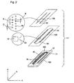
- Fig. 2 shows an enlarged axonometric view of an actuating assembly 111 of an ink jet printhead according to the known art, made of a die 100 of semiconductor material (usually Silicon), on the upper face of which resistors 27 have been made for emission of the droplets of ink, driving circuits 62 for driving the resistors 27, soldering pads 77 for connecting the head to an electronic controller not shown in the figure, and which bears a pass-through slot 102 through which the ink flows from a reservoir not shown in the figure.
- a basin 76 Around the upper edge of the slot 102 a basin 76 has been made, the characteristics and functions of which are as described in detail in Italian patent application TO 98A 000562 .
- a layer 105 of photopolymer having, usually though not exclusively, a thickness less than or equal to 25 ⁇ m in which, by means of known photolithographic techniques, a plurality of ducts 53 and a plurality of chambers 57 positioned locally to the resistors 27 have been made.
- a nozzle plate 106 Stuck on the photopolymer 105 is a nozzle plate 106, generally made of a plate of gold-plated nickel or kapton, of thickness less than or equal to 50 ⁇ m, bearing a plurality of nozzles 56, each nozzle 56 being in correspondence with a chamber 57.
- the nozzles 56 have a diameter D of between 10 and 60 ⁇ m, while their centres are usually spaced apart by a pitch A of 1/300 th or 1/600 th of an inch (84.6 ⁇ m or 42.3 ⁇ m).
- the x, y and z axes, already defmed in Fig. 1 are also shown in Fig. 2 .
- Fig. 3 is an axonometric enlargement of two chambers 57, adjacent and communicating with the slot 102 through the basin 76 and the ducts 53 made in the layer of photopolymer 105.
- the ducts 53 have a length l and a rectangular cross-section having a depth a and a width b.
- the chambers 57 have a depth d, substantially equal to the depth a of the ducts 53.
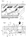
- FIG. 4 A section of an ejector 55 can be seen in Fig. 4 , where the following are shown, in addition to the items already mentioned: a reservoir 103 containing ink 142, a droplet 51 of ink, a vapour bubble 65, a meniscus 54 in correspondence with the surface of separation between the ink and the air, an external edge 66 and arrows 52 which indicate the prevalent direction of motion of the ink.
- the bubble is represented as a variable capacitance C b .
- the front leg 70 comprises a fixed impedance L f , R f corresponding substantially to the chamber 57, a variable impedance L u , R u corresponding substantially to the nozzle 56, and a deviator T which, during the step in which the droplet 51 is formed, inserts a variable resistance Rg substantially corresponding to the droplet, whereas, during the steps of withdrawal of the meniscus 54, of filling of the nozzle, of subsequent oscillation and damping of the meniscus, inserts a capacitance C m substantially corresponding to the meniscus itself.
- Ejection of the ink takes places in accordance with the following steps:
- the time constant ⁇ is a function of the width b , while it is independent of both the depth a and the length l .
- Document US5519424 discloses an ink jet print head in which the ink contained in a chamber is expelled through a nozzle in the form of droplets by the rapid heating of a heating element inside the chamber.
- the chamber is of polygonal form and communicates with an ink supply channel disposed at a corner of the chamber.
- Document EP0867292 discloses nozzle plate designs for ink jet printers and an apparatus and methods for making the nozzle plates.
- the nozzle plates are made from a polymeric material having a thickness sufficient to provide a plurality of flow features and nozzle holes aligned substantially along opposed edges of the nozzle plate wherein the flow features are ablated in the nozzle plates with depths which provide decoupling of the flow features from the nozzle holes so that the flow features and nozzle holes can be independently designed in order to improve the nozzle plate performance.
- the object of this invention is to render the emission frequency of the droplets of ink maximal by making the time constant ⁇ of the ejector as short as possible, while at the same time satisfying the condition of critical damping of the meniscus.
- Another object is to increase the degrees of freedom of the design of the ejector, by having the additional parameter consisting of the number N of elementary ducts in parallel.
- Yet another object is to filter the ink of any impurities that may be present.
- the width g according to this invention is, though not exclusively, between 3 and 15 ⁇ m.
- N is generally not an integer, and must be rounded to the nearest whole number: this causes a slight deviation from the condition of critical damping, which may be recovered with a slight variation of the length l of the elementary duct 72.
- FIG. 7 shows a preferred embodiment of the invention. The following are shown in the figure:
- the nozzles 56' are produced directly on a "flat cable", which in this way performs the function of nozzle plate.
- the flat cable 130 can be made, for instance, of Kapton.
- the elementary ducts 72' are made directly on the lower surface 114 of the flat cable 130, together with the chamber 74', using for instance an excimer laser.
Landscapes
- Engineering & Computer Science (AREA)
- Manufacturing & Machinery (AREA)
- Physics & Mathematics (AREA)
- Geometry (AREA)
- Particle Formation And Scattering Control In Inkjet Printers (AREA)
- Ink Jet (AREA)
- Impact Printers (AREA)
- Mechanical Pencils And Projecting And Retracting Systems Therefor, And Multi-System Writing Instruments (AREA)
Claims (9)
- Thermo-Tintenstrahldruckkopf (40), bestehend aus einem Behälter (103) zur Aufnahme von Tinte und mehreren Ejektoren (73), von denen jeder wiederum eine Kammer (74'), ein Die (100) und ein Flachkabel (130) aufweist, das mit Düsen (56') versehen ist, wobei das Flachkabel eine Unterseite (114) und eine Oberseite gegenüber der Unterseite (114) hat, sich die Düsen (56') von der Oberseite zu den Kammern (74') erstrecken und die Unterseite (114) am Die (100) angeordnet ist,
wobei jede der Kammern (74) an der Unterseite (114) des Flachkabels (130) gebildet ist,
dadurch gekennzeichnet, dass
jede der Kammern (74') fluidmäßig durch mehrere Elementarkanäle (72') mit dem Behälter (103) verbunden ist, die an der Unterseite (114) des Flachkabels (130) gebildet sind, und jede der Kammern (74') durch drei kontinuierliche Wände und eine vierte Wand gebildet sind, die durch die Elementarkanäle (72') unterbrochen ist. - Druckkopf nach Anspruch 1, bei dem die Elementarkanäle (72') parallel zueinander sind.
- Druckkopf nach Anspruch 1, bei dem jede der Kammern (74') einen Boden (67) am Die (100) hat, und die Elementarkanäle (72') fluidmäßig mit der Kammer (74') durch den Boden (67) verbunden sind.
- Druckkopf nach Anspruch 3, bei dem jede der Kammern (74') einen Widerstand (27) aufweist, der am Boden (67) der Kammer (74') angeordnet ist.
- Druckkopf nach Anspruch 1, weiterhin aufweisend einen Schlitz (102) und ein Sammelbecken (76) nahe dem Schlitz (102), und bei dem jede der Kammern (74') fluidmäßig mit dem Sammelbecken (76) durch die Elementarkanäle (72') verbunden ist.
- Druckkopf nach Anspruch 1, bei dem jeder der Elementarkanäle (72') einen im Wesentlichen rechteckigen Querschnitt mit einer Höhe (f) und einer Breite (g) hat.
- Druckkopf nach Anspruch 6, bei dem die Breite (g) zwischen 3 und 15 µm liegt.
- Druckkopf nach Anspruch 6, bei dem die Düsen einen Außenrand (66) haben, und der Druckkopf außerdem die Tinte aufweist, die ein meniskusförmiges Element am Außenrand bildet, und bei dem die Breite (g) gegeben ist durch die Formel:

in der v die Viskosität der Tinte und τ die jedem der Ejektoren (73) zugeordnete Zeitkonstante ist und die Elementarkanäle (72') in einer Anzahl N vorhanden sind, die gegeben ist durch
wobei R' der hydraulische Widerstand, L' die hydraulische Trägheit jedes Elementarkanals (72) und Cm die hydraulische Nachgiebigkeit des meniskusförmigen Elements (54) ist, so dass das meniskusförmige Element eine kritische Dämpfung bei beliebigem τ zugeordnetem Wert hat. - Druckkopf nach Anspruch 1, bei dem jede der Kammern (74') einen Widerstand (27) aufweist, der am Boden (64) der Kammer (74') angeordnet ist, und bei dem das Die (100) eine Oberseite hat, die der Unterseite (114) des Flachkabels (130) zugewandt ist, und der Widerstand (27) an der Oberseite des Dies (100) gebildet ist.
Applications Claiming Priority (2)
| Application Number | Priority Date | Filing Date | Title |
|---|---|---|---|
| IT1999AO000002A IT1309735B1 (it) | 1999-12-27 | 1999-12-27 | Testina a canali multipli di alimentazione dell'inchiostro |
| EP00987625A EP1255646B1 (de) | 1999-12-27 | 2000-12-19 | Druckkopf mit mehreren tintenzufuhrkanälen |
Related Parent Applications (1)
| Application Number | Title | Priority Date | Filing Date |
|---|---|---|---|
| EP00987625A Division EP1255646B1 (de) | 1999-12-27 | 2000-12-19 | Druckkopf mit mehreren tintenzufuhrkanälen |
Publications (2)
| Publication Number | Publication Date |
|---|---|
| EP1661708A1 EP1661708A1 (de) | 2006-05-31 |
| EP1661708B1 true EP1661708B1 (de) | 2009-02-18 |
Family
ID=11334382
Family Applications (2)
| Application Number | Title | Priority Date | Filing Date |
|---|---|---|---|
| EP00987625A Expired - Lifetime EP1255646B1 (de) | 1999-12-27 | 2000-12-19 | Druckkopf mit mehreren tintenzufuhrkanälen |
| EP05028378A Expired - Lifetime EP1661708B1 (de) | 1999-12-27 | 2000-12-19 | Druckkopf mit mehreren Tintenzufuhrkanälen |
Family Applications Before (1)
| Application Number | Title | Priority Date | Filing Date |
|---|---|---|---|
| EP00987625A Expired - Lifetime EP1255646B1 (de) | 1999-12-27 | 2000-12-19 | Druckkopf mit mehreren tintenzufuhrkanälen |
Country Status (8)
| Country | Link |
|---|---|
| US (3) | US6719913B2 (de) |
| EP (2) | EP1255646B1 (de) |
| AT (2) | ATE321665T1 (de) |
| AU (1) | AU2396101A (de) |
| DE (2) | DE60027050T2 (de) |
| ES (1) | ES2259623T3 (de) |
| IT (1) | IT1309735B1 (de) |
| WO (1) | WO2001047715A1 (de) |
Families Citing this family (15)
| Publication number | Priority date | Publication date | Assignee | Title |
|---|---|---|---|---|
| AUPO983897A0 (en) * | 1997-10-17 | 1997-11-06 | Soltec Research Pty Ltd | Topical antifungal composition |
| EP1769872A3 (de) * | 2001-12-20 | 2007-04-11 | Hewlett-Packard Company | Verfahren zur laserbearbeitung eines flüssigkeitsschlitzes |
| US7357486B2 (en) * | 2001-12-20 | 2008-04-15 | Hewlett-Packard Development Company, L.P. | Method of laser machining a fluid slot |
| JP2005028708A (ja) | 2003-07-11 | 2005-02-03 | Fuji Photo Film Co Ltd | インクジェットヘッドおよびインクジェット記録装置 |
| JP4362057B2 (ja) * | 2003-09-24 | 2009-11-11 | 富士フイルム株式会社 | インクジェットヘッドおよびインクジェット記録装置 |
| US7524046B2 (en) | 2004-01-21 | 2009-04-28 | Silverbrook Research Pty Ltd | Printhead assembly for a web printing system |
| US20050157103A1 (en) * | 2004-01-21 | 2005-07-21 | Kia Silverbrook | Ink fluid delivery system for a printer |
| JP2005205721A (ja) * | 2004-01-22 | 2005-08-04 | Sony Corp | 液体吐出ヘッド及び液体吐出装置 |
| KR100765315B1 (ko) * | 2004-07-23 | 2007-10-09 | 삼성전자주식회사 | 기판과 일체로 이루어진 필터링 부재를 구비하는 잉크젯헤드 및 그 제조방법. |
| US8292408B2 (en) * | 2006-06-01 | 2012-10-23 | Telecom Italia S.P.A. | Inkjet printhead |
| US8647273B2 (en) | 2007-06-21 | 2014-02-11 | RF Science & Technology, Inc. | Non-invasive weight and performance management |
| US20090027457A1 (en) | 2007-07-25 | 2009-01-29 | Clark Garrett E | Fluid ejection device |
| EP2459384A4 (de) | 2009-07-31 | 2013-02-20 | Hewlett Packard Development Co | Tintenstrahldruckkopf und verfahren mit zentralem tintenzuführungskanal |
| US8425787B2 (en) * | 2009-08-26 | 2013-04-23 | Hewlett-Packard Development Company, L.P. | Inkjet printhead bridge beam fabrication method |
| US8371683B2 (en) | 2010-12-23 | 2013-02-12 | Palo Alto Research Center Incorporated | Particle removal device for ink jet printer |
Family Cites Families (17)
| Publication number | Priority date | Publication date | Assignee | Title |
|---|---|---|---|---|
| US4502060A (en) * | 1983-05-02 | 1985-02-26 | Hewlett-Packard Company | Barriers for thermal ink jet printers |
| US6113218A (en) * | 1990-09-21 | 2000-09-05 | Seiko Epson Corporation | Ink-jet recording apparatus and method for producing the head thereof |
| JP3102062B2 (ja) * | 1991-06-03 | 2000-10-23 | セイコーエプソン株式会社 | インクジェット記録ヘッド |
| IT1250371B (it) * | 1991-12-24 | 1995-04-07 | Olivetti & Co Spa | Testina di stampa a getto d'inchiostro perfezionata. |
| US5278584A (en) | 1992-04-02 | 1994-01-11 | Hewlett-Packard Company | Ink delivery system for an inkjet printhead |
| EP0867289B1 (de) * | 1994-04-20 | 2000-03-15 | Seiko Epson Corporation | Tintenstrahlaufzeichnungsgerät |
| US5666143A (en) | 1994-07-29 | 1997-09-09 | Hewlett-Packard Company | Inkjet printhead with tuned firing chambers and multiple inlets |
| US5734399A (en) | 1995-07-11 | 1998-03-31 | Hewlett-Packard Company | Particle tolerant inkjet printhead architecture |
| US6162589A (en) * | 1998-03-02 | 2000-12-19 | Hewlett-Packard Company | Direct imaging polymer fluid jet orifice |
| US6158843A (en) * | 1997-03-28 | 2000-12-12 | Lexmark International, Inc. | Ink jet printer nozzle plates with ink filtering projections |
| US6019907A (en) * | 1997-08-08 | 2000-02-01 | Hewlett-Packard Company | Forming refill for monolithic inkjet printhead |
| US6322201B1 (en) * | 1997-10-22 | 2001-11-27 | Hewlett-Packard Company | Printhead with a fluid channel therethrough |
| US6540335B2 (en) * | 1997-12-05 | 2003-04-01 | Canon Kabushiki Kaisha | Ink jet print head and ink jet printing device mounting this head |
| ITTO980562A1 (it) | 1998-06-29 | 1999-12-29 | Olivetti Lexikon Spa | Testina di stampa a getto di inchiostro |
| US6309054B1 (en) * | 1998-10-23 | 2001-10-30 | Hewlett-Packard Company | Pillars in a printhead |
| US6286941B1 (en) * | 1998-10-26 | 2001-09-11 | Hewlett-Packard Company | Particle tolerant printhead |
| US6499835B1 (en) * | 2001-10-30 | 2002-12-31 | Hewlett-Packard Company | Ink delivery system for an inkjet printhead |
-
1999
- 1999-12-27 IT IT1999AO000002A patent/IT1309735B1/it active
-
2000
- 2000-12-19 ES ES00987625T patent/ES2259623T3/es not_active Expired - Lifetime
- 2000-12-19 WO PCT/IT2000/000534 patent/WO2001047715A1/en not_active Ceased
- 2000-12-19 DE DE60027050T patent/DE60027050T2/de not_active Expired - Lifetime
- 2000-12-19 DE DE60041609T patent/DE60041609D1/de not_active Expired - Fee Related
- 2000-12-19 EP EP00987625A patent/EP1255646B1/de not_active Expired - Lifetime
- 2000-12-19 AT AT00987625T patent/ATE321665T1/de not_active IP Right Cessation
- 2000-12-19 AT AT05028378T patent/ATE423008T1/de not_active IP Right Cessation
- 2000-12-19 US US10/169,114 patent/US6719913B2/en not_active Expired - Lifetime
- 2000-12-19 EP EP05028378A patent/EP1661708B1/de not_active Expired - Lifetime
- 2000-12-19 AU AU23961/01A patent/AU2396101A/en not_active Abandoned
-
2003
- 2003-12-03 US US10/725,588 patent/US7052116B2/en not_active Expired - Fee Related
-
2006
- 2006-02-02 US US11/345,489 patent/US7637598B2/en not_active Expired - Lifetime
Also Published As
| Publication number | Publication date |
|---|---|
| ATE423008T1 (de) | 2009-03-15 |
| AU2396101A (en) | 2001-07-09 |
| EP1255646B1 (de) | 2006-03-29 |
| DE60027050T2 (de) | 2007-04-12 |
| EP1661708A1 (de) | 2006-05-31 |
| US20030061987A1 (en) | 2003-04-03 |
| ATE321665T1 (de) | 2006-04-15 |
| US20060192816A1 (en) | 2006-08-31 |
| US20040109044A1 (en) | 2004-06-10 |
| US7637598B2 (en) | 2009-12-29 |
| US6719913B2 (en) | 2004-04-13 |
| EP1255646A1 (de) | 2002-11-13 |
| DE60027050D1 (de) | 2006-05-18 |
| WO2001047715A1 (en) | 2001-07-05 |
| ITAO990002A1 (it) | 2001-06-27 |
| DE60041609D1 (de) | 2009-04-02 |
| ES2259623T3 (es) | 2006-10-16 |
| IT1309735B1 (it) | 2002-01-30 |
| US7052116B2 (en) | 2006-05-30 |
Similar Documents
| Publication | Publication Date | Title |
|---|---|---|
| EP1661708B1 (de) | Druckkopf mit mehreren Tintenzufuhrkanälen | |
| EP1282521B1 (de) | Monolithischer druckkopf mit mehreren tintenzuführkanälen und entsprechende verfahren zur herstellung | |
| US6966112B2 (en) | Methods of fabricating FIT firing chambers of different drop weights on a single printhead | |
| JP3871320B2 (ja) | インクジェット記録ヘッド | |
| US8651625B2 (en) | Fluid ejection device | |
| EP1287995B1 (de) | Flüssigkeitsausstosskopf und damit versehene Bilderzeugungsvorrichtung | |
| TWI309997B (en) | Orifice plate and method of forming orifice plate for fluid ejection device | |
| JP4724490B2 (ja) | 液体吐出ヘッド | |
| JP2003145779A (ja) | ペン本体にダイ接着するための微細機械加工されたシリコン・インターロック構造と方法 | |
| JP2007516876A (ja) | 液滴射出集成体 | |
| JP4018272B2 (ja) | インクジェットプリントヘッド及び該ヘッドを搭載するインクジェットプリンティングデバイス | |
| EP0465071A2 (de) | Tintenstrahldruckkopf | |
| JP2002166571A (ja) | 記録ヘッドのバッファ室への気泡充填方法および記録装置 | |
| US7478476B2 (en) | Methods of fabricating fit firing chambers of different drop wights on a single printhead | |
| CN100446976C (zh) | 点滴喷射组件 | |
| CN100453321C (zh) | 点滴喷射组件 | |
| EP2032366B1 (de) | Tintenstrahldruckkopf | |
| JP2007516877A (ja) | 液滴射出集成体 | |
| JPH0560845U (ja) | インクジェットプリンタ用印字ヘッド |
Legal Events
| Date | Code | Title | Description |
|---|---|---|---|
| PUAI | Public reference made under article 153(3) epc to a published international application that has entered the european phase |
Free format text: ORIGINAL CODE: 0009012 |
|
| AC | Divisional application: reference to earlier application |
Ref document number: 1255646 Country of ref document: EP Kind code of ref document: P |
|
| AK | Designated contracting states |
Kind code of ref document: A1 Designated state(s): AT BE CH CY DE DK ES FI FR GB GR IE IT LI LU MC NL PT SE TR |
|
| 17P | Request for examination filed |
Effective date: 20061122 |
|
| AKX | Designation fees paid |
Designated state(s): AT BE CH CY DE DK ES FI FR GB GR IE IT LI LU MC NL PT SE TR |
|
| 17Q | First examination report despatched |
Effective date: 20070129 |
|
| GRAP | Despatch of communication of intention to grant a patent |
Free format text: ORIGINAL CODE: EPIDOSNIGR1 |
|
| GRAS | Grant fee paid |
Free format text: ORIGINAL CODE: EPIDOSNIGR3 |
|
| GRAA | (expected) grant |
Free format text: ORIGINAL CODE: 0009210 |
|
| AC | Divisional application: reference to earlier application |
Ref document number: 1255646 Country of ref document: EP Kind code of ref document: P |
|
| AK | Designated contracting states |
Kind code of ref document: B1 Designated state(s): AT BE CH CY DE DK ES FI FR GB GR IE IT LI LU MC NL PT SE TR |
|
| REG | Reference to a national code |
Ref country code: GB Ref legal event code: FG4D |
|
| REG | Reference to a national code |
Ref country code: CH Ref legal event code: EP |
|
| REG | Reference to a national code |
Ref country code: IE Ref legal event code: FG4D |
|
| REF | Corresponds to: |
Ref document number: 60041609 Country of ref document: DE Date of ref document: 20090402 Kind code of ref document: P |
|
| PG25 | Lapsed in a contracting state [announced via postgrant information from national office to epo] |
Ref country code: FI Free format text: LAPSE BECAUSE OF FAILURE TO SUBMIT A TRANSLATION OF THE DESCRIPTION OR TO PAY THE FEE WITHIN THE PRESCRIBED TIME-LIMIT Effective date: 20090218 Ref country code: NL Free format text: LAPSE BECAUSE OF FAILURE TO SUBMIT A TRANSLATION OF THE DESCRIPTION OR TO PAY THE FEE WITHIN THE PRESCRIBED TIME-LIMIT Effective date: 20090218 Ref country code: ES Free format text: LAPSE BECAUSE OF FAILURE TO SUBMIT A TRANSLATION OF THE DESCRIPTION OR TO PAY THE FEE WITHIN THE PRESCRIBED TIME-LIMIT Effective date: 20090529 |
|
| NLV1 | Nl: lapsed or annulled due to failure to fulfill the requirements of art. 29p and 29m of the patents act | ||
| PG25 | Lapsed in a contracting state [announced via postgrant information from national office to epo] |
Ref country code: AT Free format text: LAPSE BECAUSE OF FAILURE TO SUBMIT A TRANSLATION OF THE DESCRIPTION OR TO PAY THE FEE WITHIN THE PRESCRIBED TIME-LIMIT Effective date: 20090218 Ref country code: SE Free format text: LAPSE BECAUSE OF FAILURE TO SUBMIT A TRANSLATION OF THE DESCRIPTION OR TO PAY THE FEE WITHIN THE PRESCRIBED TIME-LIMIT Effective date: 20090518 |
|
| PG25 | Lapsed in a contracting state [announced via postgrant information from national office to epo] |
Ref country code: BE Free format text: LAPSE BECAUSE OF FAILURE TO SUBMIT A TRANSLATION OF THE DESCRIPTION OR TO PAY THE FEE WITHIN THE PRESCRIBED TIME-LIMIT Effective date: 20090218 |
|
| PG25 | Lapsed in a contracting state [announced via postgrant information from national office to epo] |
Ref country code: PT Free format text: LAPSE BECAUSE OF FAILURE TO SUBMIT A TRANSLATION OF THE DESCRIPTION OR TO PAY THE FEE WITHIN THE PRESCRIBED TIME-LIMIT Effective date: 20090727 Ref country code: DK Free format text: LAPSE BECAUSE OF FAILURE TO SUBMIT A TRANSLATION OF THE DESCRIPTION OR TO PAY THE FEE WITHIN THE PRESCRIBED TIME-LIMIT Effective date: 20090218 |
|
| PLBE | No opposition filed within time limit |
Free format text: ORIGINAL CODE: 0009261 |
|
| STAA | Information on the status of an ep patent application or granted ep patent |
Free format text: STATUS: NO OPPOSITION FILED WITHIN TIME LIMIT |
|
| 26N | No opposition filed |
Effective date: 20091119 |
|
| PG25 | Lapsed in a contracting state [announced via postgrant information from national office to epo] |
Ref country code: MC Free format text: LAPSE BECAUSE OF NON-PAYMENT OF DUE FEES Effective date: 20100701 |
|
| REG | Reference to a national code |
Ref country code: CH Ref legal event code: PL |
|
| GBPC | Gb: european patent ceased through non-payment of renewal fee |
Effective date: 20091219 |
|
| REG | Reference to a national code |
Ref country code: FR Ref legal event code: ST Effective date: 20100831 |
|
| PG25 | Lapsed in a contracting state [announced via postgrant information from national office to epo] |
Ref country code: FR Free format text: LAPSE BECAUSE OF NON-PAYMENT OF DUE FEES Effective date: 20091231 Ref country code: CH Free format text: LAPSE BECAUSE OF NON-PAYMENT OF DUE FEES Effective date: 20091231 Ref country code: LI Free format text: LAPSE BECAUSE OF NON-PAYMENT OF DUE FEES Effective date: 20091231 Ref country code: IE Free format text: LAPSE BECAUSE OF NON-PAYMENT OF DUE FEES Effective date: 20091219 Ref country code: GR Free format text: LAPSE BECAUSE OF FAILURE TO SUBMIT A TRANSLATION OF THE DESCRIPTION OR TO PAY THE FEE WITHIN THE PRESCRIBED TIME-LIMIT Effective date: 20090519 |
|
| PG25 | Lapsed in a contracting state [announced via postgrant information from national office to epo] |
Ref country code: DE Free format text: LAPSE BECAUSE OF NON-PAYMENT OF DUE FEES Effective date: 20100701 |
|
| PG25 | Lapsed in a contracting state [announced via postgrant information from national office to epo] |
Ref country code: GB Free format text: LAPSE BECAUSE OF NON-PAYMENT OF DUE FEES Effective date: 20091219 |
|
| PG25 | Lapsed in a contracting state [announced via postgrant information from national office to epo] |
Ref country code: IT Free format text: LAPSE BECAUSE OF FAILURE TO SUBMIT A TRANSLATION OF THE DESCRIPTION OR TO PAY THE FEE WITHIN THE PRESCRIBED TIME-LIMIT Effective date: 20090218 |
|
| PG25 | Lapsed in a contracting state [announced via postgrant information from national office to epo] |
Ref country code: LU Free format text: LAPSE BECAUSE OF NON-PAYMENT OF DUE FEES Effective date: 20091219 |
|
| PG25 | Lapsed in a contracting state [announced via postgrant information from national office to epo] |
Ref country code: TR Free format text: LAPSE BECAUSE OF FAILURE TO SUBMIT A TRANSLATION OF THE DESCRIPTION OR TO PAY THE FEE WITHIN THE PRESCRIBED TIME-LIMIT Effective date: 20090218 |
|
| PG25 | Lapsed in a contracting state [announced via postgrant information from national office to epo] |
Ref country code: CY Free format text: LAPSE BECAUSE OF FAILURE TO SUBMIT A TRANSLATION OF THE DESCRIPTION OR TO PAY THE FEE WITHIN THE PRESCRIBED TIME-LIMIT Effective date: 20090218 |