EP1661671A1 - Roboter mit Führungsvorrichtung für eine Versorgungsleitung - Google Patents
Roboter mit Führungsvorrichtung für eine Versorgungsleitung Download PDFInfo
- Publication number
- EP1661671A1 EP1661671A1 EP05024915A EP05024915A EP1661671A1 EP 1661671 A1 EP1661671 A1 EP 1661671A1 EP 05024915 A EP05024915 A EP 05024915A EP 05024915 A EP05024915 A EP 05024915A EP 1661671 A1 EP1661671 A1 EP 1661671A1
- Authority
- EP
- European Patent Office
- Prior art keywords
- conduit
- forearm
- managing device
- robot
- umbilical
- Prior art date
- Legal status (The legal status is an assumption and is not a legal conclusion. Google has not performed a legal analysis and makes no representation as to the accuracy of the status listed.)
- Granted
Links
- 210000000245 forearm Anatomy 0.000 claims abstract description 48
- 210000000707 wrist Anatomy 0.000 claims abstract description 26
- 239000012636 effector Substances 0.000 claims description 12
- 239000000463 material Substances 0.000 description 2
- 230000002093 peripheral effect Effects 0.000 description 2
- 230000008602 contraction Effects 0.000 description 1
- 230000004048 modification Effects 0.000 description 1
- 238000012986 modification Methods 0.000 description 1
- 238000000926 separation method Methods 0.000 description 1
Images


Classifications
-
- B—PERFORMING OPERATIONS; TRANSPORTING
- B25—HAND TOOLS; PORTABLE POWER-DRIVEN TOOLS; MANIPULATORS
- B25J—MANIPULATORS; CHAMBERS PROVIDED WITH MANIPULATION DEVICES
- B25J19/00—Accessories fitted to manipulators, e.g. for monitoring, for viewing; Safety devices combined with or specially adapted for use in connection with manipulators
- B25J19/0025—Means for supplying energy to the end effector
-
- Y—GENERAL TAGGING OF NEW TECHNOLOGICAL DEVELOPMENTS; GENERAL TAGGING OF CROSS-SECTIONAL TECHNOLOGIES SPANNING OVER SEVERAL SECTIONS OF THE IPC; TECHNICAL SUBJECTS COVERED BY FORMER USPC CROSS-REFERENCE ART COLLECTIONS [XRACs] AND DIGESTS
- Y10—TECHNICAL SUBJECTS COVERED BY FORMER USPC
- Y10T—TECHNICAL SUBJECTS COVERED BY FORMER US CLASSIFICATION
- Y10T74/00—Machine element or mechanism
- Y10T74/20—Control lever and linkage systems
- Y10T74/20207—Multiple controlling elements for single controlled element
- Y10T74/20305—Robotic arm
Definitions
- the preset invention relates to a managing device, for an umbilical member including a cable and/or a tube of an industrial robot, and a robot having the managing device.
- the robot when an industrial robot is used for an operation, the robot is required to be provided with an umbilical member including a cable and/or a tube for transmitting power or a signal to an end effector attached to the end of a wrist element of the robot.
- an umbilical member including a cable and/or a tube for transmitting power or a signal to an end effector attached to the end of a wrist element of the robot.
- the umbilical member When the umbilical member is arranged around the wrist element of a robot arm, the umbilical member may contact the arm or the other external equipment and may be worn or damaged. In order to avoid such an inconvenience, several configurations has been proposed.
- Patent Publication No. EP1060057 discloses a configuration in which a flexible conduit, containing a cable and a tube, is arranged along a forearm of a robot, by means of a holding means arranged on the forearm, and slidably holds the conduit.
- an object of the present invention is to provide a managing device for an umbilical member having a simple structure, and a robot having the managing device, by which an interference region of the conduit is reduced as much as possible and an undesirable excess length of the conduit may be avoided without using the above spring, or the like.
- a managing device for supporting an umbilical member corresponding to the motion of an industrial robot, the robot having: an upper arm; a forearm movably connected to the upper arm via a joint; a wrist element rotatably mounted to the end of the forearm; an end effector attached to the wrist element; and a flexible umbilical member connected the end effector
- the managing device comprises: a first supporting member, mounted on the upper arm, for fixing or twistably supporting the umbilical member; a holding member, mounted on the forearm adjacent to the joint, for holding the umbilical member such that the umbilical member may slide relative to the holding member and may rotate about axes along and perpendicular to the sliding direction of the umbilical member; and a second supporting member, mounted on the wrist element so as to integrally rotate with the wrist element, for fixing or twistably supporting the umbilical member; wherein the first and second supporting members and the holding member are positioned such that a slack of
- the holding member is preferably positioned near the joint such that the slack of the umbilical member is positioned around the joint.
- the managing device may further comprise a means for reducing the sliding resistance between the forearm and the umbilical member.
- the means for reducing the sliding resistance may be a protrusion arranged on a site of forearm abutting the umbilical member.
- the means for reducing the sliding resistance may be a protrusion arranged on a site of the umbilical member abutting the forearm.
- the protrusion may be a ring member.
- a robot having a managing device according to the invention.
- FIGs. 1a and 1b show a total configuration of a managing device of the invention, each showing a robot from an upper arm to an end effector.
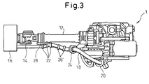
- a robot 1 includes an upper arm 10; a forearm 12 movably connected to the upper arm 10 via a joint 11; a wrist element 14 rotatably mounted to the end of the forearm 12; and an end effector 16 attached to the wrist element 14. Power and a signal are sent to the end effector 16 by means of an umbilical member 18 constituted by a flexible conduit through which a cable and a tube extend.
- the umbilical member 18 is arranged along a base (not shown) of the robot 1, the upper arm 10, the forearm 12 and the wrist element 14 and connected to the end effector 16.
- a first supporting member or a conduit supporting member 20 is arranged on the upper arm 10, and a second supporting member or a conduit supporting member 22 is arranged on the wrist element 14.
- the umbilical member or the conduit 18 is fixed or twistably supported by the first and second supporting members 20 and 22.
- the conduit 18 is held by a holding means 24 arranged between the first and second supporting members 20 and 22 and, in particular, adjacent to the side of the forearm 12 and preferably near the joint 11, such that the conduit 18 may slide relative to the holding member 24 and may rotate about axes along and perpendicular to the sliding direction of the conduit.
- the holding member 24 has, for example, a ring shape as shown.
- the holding member 24 is positioned at a site on the forearm 12 close to the joint 11 as possible (for example, a proximal end of the forearm 12). Due to this configuration, a gap between the conduit 18 and the forearm 12 is reduced, thereby the possibility of interference between the conduit and an external equipment may be minimized.
- a first state as shown in Figs. 1a and 1b, in which the conduit 18 is not wound around the forearm 12, the conduit 18 between the first supporting member 20 and the holding member 24 (in particular, near the joint 11) has an excess length or a slack of the conduit.
- Figs. 2a to 2c show a second state, in which the conduit 18 is wound around the forearm 12 by the rotation of the wrist element 14.
- the second supporting member 22 is also rotated by the rotation of the wrist element 14. Therefore, the conduit 18 is drawn toward the end effector 16 and slides relative to the holding member 24 to some extent. Further, the conduit 18 is wound on to the forearm 12 between the first and second supporting members 20 and 22. Therefore, the conduit 18 is as close to the forearm 12 as possible and the possibility of interference between the conduit and the external equipment may be remarkably reduced.
- a protrusion for example, a ring member 26 as shown
- a contact area between the conduit 18 and the peripheral surface of the forearm 12 may be zero or reduced, whereby a frictional force or a sliding resistance acting on the conduit 18 being wounded on to the forearm 12 is remarkably reduced.
- a protrusion for example, a ring member 26' similar to the ring member 26
- a protrusion may be arranged on the conduit 18, not on the forearm 12.
- the conduit 18 between the conduit supporting members 20 and 22 is unwounded from the forearm 12.
- the unwounded conduit may be apart from the forearm and hang down such that the conduit undesirably sags. Therefore, in the device of the publication, it may be necessary to provide a spring or the like so as to absorb the sag.
- the longitudinal direction of the excess length part of the conduit 18, in the first state, generated by the sliding motion of the conduit relative to the holding member 24 toward the end effector 16 may be kept to be almost the same as the sliding direction of the conduit at the holding member 24. Therefore, when the wrist element 14 rotates such that the conduit 18 is unwounded from the forearm 12, the conduit 18 may smoothly slide, at the holding member 24, toward the upper arm 10, without using an auxiliary means such as a spring.
- the conduit 18 in the second state may be fitted to the forearm 12 over the whole length thereof, whereby an interference region of the conduit may be minimized. Further, advantageously, the excess length of the conduit 18 may be generated around the joint 11 where interference does not need to be taken into consideration.
- the motion of the conduit 18 may be made more smooth.
- the preferable angle of the holding member 24 may vary according to the dimension and the material of the conduit 18 and the size of the forearm. In many cases, it is preferable that an angle between the longitudinal direction of the conduit 18 at the holding member 24 and the longitudinal direction of the forearm 12 is within a range of 20 - 70 degree.
- the second supporting member 22 on the wrist element 14 It greatly depends on a distance L between the second supporting member 22 on the wrist element 14 and the holding member 24 (as shown in Fig. 1b), whether the conduit 18 may smoothly slide relative to the holding member 24 toward the upper arm (i.e., from the second state to the first state). Therefore, if the length of the forearm 12 is relatively long, as shown in Fig. 1a or 2a, the second supporting member 22 is preferably displaced toward the forearm 12 to some extent by means of a bracket 28 attached to the wrist element 14, so as to suitably shorten the distance L corresponding to the dimension and the material of the conduit 18.
- the excess length or the slack of the umbilical member generated by the rotation of the wrist element is positioned between the first supporting member and the holding member. Therefore, an excess length is not generated around the forearm where interference may cause a problem.
Landscapes
- Engineering & Computer Science (AREA)
- Robotics (AREA)
- Mechanical Engineering (AREA)
- Manipulator (AREA)
Applications Claiming Priority (1)
| Application Number | Priority Date | Filing Date | Title |
|---|---|---|---|
| JP2004344008A JP2006150496A (ja) | 2004-11-29 | 2004-11-29 | ロボットの線条体支持装置及び線条体支持装置を備えたロボット |
Publications (2)
| Publication Number | Publication Date |
|---|---|
| EP1661671A1 true EP1661671A1 (de) | 2006-05-31 |
| EP1661671B1 EP1661671B1 (de) | 2008-03-26 |
Family
ID=35969123
Family Applications (1)
| Application Number | Title | Priority Date | Filing Date |
|---|---|---|---|
| EP05024915A Ceased EP1661671B1 (de) | 2004-11-29 | 2005-11-15 | Roboter mit Führungsvorrichtung für eine Versorgungsleitung |
Country Status (5)
| Country | Link |
|---|---|
| US (1) | US20060196300A1 (de) |
| EP (1) | EP1661671B1 (de) |
| JP (1) | JP2006150496A (de) |
| CN (1) | CN1781680A (de) |
| DE (1) | DE602005005606T2 (de) |
Cited By (2)
| Publication number | Priority date | Publication date | Assignee | Title |
|---|---|---|---|---|
| WO2020219480A1 (en) * | 2019-04-25 | 2020-10-29 | Berkshire Grey, Inc. | Systems and methods for maintaining vacuum hose life in hose routing systems in programmable motion systems |
| US12151372B2 (en) | 2019-02-27 | 2024-11-26 | Berkshire Grey Operating Company, Inc. | Systems and methods for hose routing in programmable motion systems |
Families Citing this family (11)
| Publication number | Priority date | Publication date | Assignee | Title |
|---|---|---|---|---|
| JP2008238320A (ja) * | 2007-03-27 | 2008-10-09 | Fanuc Ltd | 作業ツールを備えたロボット |
| JP4565029B2 (ja) * | 2008-08-13 | 2010-10-20 | ファナック株式会社 | 線条体動作制限装置、および該装置を備えたロボット |
| JP4837117B2 (ja) * | 2010-04-14 | 2011-12-14 | ファナック株式会社 | ロボットアーム部の線条体配設機構 |
| JP5201186B2 (ja) * | 2010-09-16 | 2013-06-05 | 株式会社安川電機 | ロボット |
| JP6144886B2 (ja) * | 2012-09-04 | 2017-06-07 | 株式会社アマダホールディングス | 産業用ロボットのケーブル処理構造 |
| JP5661718B2 (ja) * | 2012-10-12 | 2015-01-28 | ファナック株式会社 | ロボットの線条体取付装置 |
| JP5413524B1 (ja) * | 2013-01-17 | 2014-02-12 | 株式会社安川電機 | ロボット |
| CN104339365B (zh) * | 2013-07-26 | 2017-04-12 | 株式会社安川电机 | 机器人及机器人的制造方法 |
| JP5928416B2 (ja) | 2013-07-26 | 2016-06-01 | 株式会社安川電機 | ロボットおよびロボットの製造方法 |
| CN105313141B (zh) * | 2015-12-09 | 2017-11-24 | 绵阳伦奇机器人有限公司 | 一种机器人线缆拖链 |
| JP6499701B2 (ja) | 2017-03-30 | 2019-04-10 | ファナック株式会社 | ロボット |
Citations (3)
| Publication number | Priority date | Publication date | Assignee | Title |
|---|---|---|---|---|
| US5437207A (en) * | 1991-03-21 | 1995-08-01 | Kuka Schweissanlegen & Roboter Gmbh | Multiaxial manipulator |
| EP1060057A1 (de) * | 1998-03-03 | 2000-12-20 | KUKA Schweissanlagen GmbH | Leitungsführung für einen mehrachsigen industrieroboter |
| DE10158741A1 (de) * | 2001-11-30 | 2003-06-12 | Andries Broekhuijsen | Leitungsführungsvorrichtung |
Family Cites Families (10)
| Publication number | Priority date | Publication date | Assignee | Title |
|---|---|---|---|---|
| US4507042A (en) * | 1981-10-07 | 1985-03-26 | Yaskawa Electric Mfg. Co., Ltd. | Cable support of a robot |
| DE3434899A1 (de) * | 1983-10-19 | 1985-05-23 | Kuka Schweissanlagen + Roboter Gmbh, 8900 Augsburg | Vorrichtung zum aussenseitigen halten und fuehren von versorgungsleitungen zu bewegten werkzeugen von manipulatoren |
| US4767257A (en) * | 1985-12-23 | 1988-08-30 | Mitsubishi Denki Kabushiki Kaisha | Industrial robot |
| US5893490A (en) * | 1997-01-27 | 1999-04-13 | Ingersoll-Rand Company | Hose mount for robot arm dispenser system |
| US5816736A (en) * | 1997-03-20 | 1998-10-06 | Flex-Cable, Inc. | Robot arm assembly |
| DE29814417U1 (de) * | 1998-08-11 | 1998-10-08 | Kuka Roboter GmbH, 86165 Augsburg | Schlauchhalter |
| US6439076B1 (en) * | 1999-06-17 | 2002-08-27 | Rory C. Flemmer | Robotic loader for machinery |
| DE29913063U1 (de) * | 1999-07-30 | 2000-02-17 | Igus Spritzgußteile für die Industrie GmbH, 51147 Köln | Energiezuführungskette |
| US6431018B1 (en) * | 1999-09-09 | 2002-08-13 | Fanuc Ltd. | Guide device for wiring member and/or piping member and robot with guide device |
| JP4099628B2 (ja) * | 2001-10-29 | 2008-06-11 | 株式会社安川電機 | 産業用ロボット |
-
2004
- 2004-11-29 JP JP2004344008A patent/JP2006150496A/ja active Pending
-
2005
- 2005-11-15 EP EP05024915A patent/EP1661671B1/de not_active Ceased
- 2005-11-15 DE DE602005005606T patent/DE602005005606T2/de not_active Expired - Fee Related
- 2005-11-22 US US11/283,682 patent/US20060196300A1/en not_active Abandoned
- 2005-11-28 CN CNA2005101243374A patent/CN1781680A/zh active Pending
Patent Citations (3)
| Publication number | Priority date | Publication date | Assignee | Title |
|---|---|---|---|---|
| US5437207A (en) * | 1991-03-21 | 1995-08-01 | Kuka Schweissanlegen & Roboter Gmbh | Multiaxial manipulator |
| EP1060057A1 (de) * | 1998-03-03 | 2000-12-20 | KUKA Schweissanlagen GmbH | Leitungsführung für einen mehrachsigen industrieroboter |
| DE10158741A1 (de) * | 2001-11-30 | 2003-06-12 | Andries Broekhuijsen | Leitungsführungsvorrichtung |
Cited By (6)
| Publication number | Priority date | Publication date | Assignee | Title |
|---|---|---|---|---|
| US12151372B2 (en) | 2019-02-27 | 2024-11-26 | Berkshire Grey Operating Company, Inc. | Systems and methods for hose routing in programmable motion systems |
| WO2020219480A1 (en) * | 2019-04-25 | 2020-10-29 | Berkshire Grey, Inc. | Systems and methods for maintaining vacuum hose life in hose routing systems in programmable motion systems |
| CN113748000A (zh) * | 2019-04-25 | 2021-12-03 | 伯克希尔格雷股份有限公司 | 用于维持可编程运动系统中的软管布线系统中的真空软管寿命的系统和方法 |
| US11691279B2 (en) | 2019-04-25 | 2023-07-04 | Berkshire Grey Operating Company, Inc. | Systems and methods for maintaining vacuum hose life in hose routing systems in programmable motion systems |
| CN113748000B (zh) * | 2019-04-25 | 2024-04-05 | 伯克希尔格雷营业股份有限公司 | 用于维持可编程运动系统中的软管布线系统中的真空软管寿命的系统和方法 |
| US12138797B2 (en) | 2019-04-25 | 2024-11-12 | Berkshire Grey Operating Company, Inc. | Systems and methods for maintaining vacuum hose life in hose routing systems in programmable motion systems |
Also Published As
| Publication number | Publication date |
|---|---|
| CN1781680A (zh) | 2006-06-07 |
| EP1661671B1 (de) | 2008-03-26 |
| JP2006150496A (ja) | 2006-06-15 |
| DE602005005606D1 (de) | 2008-05-08 |
| DE602005005606T2 (de) | 2009-04-16 |
| US20060196300A1 (en) | 2006-09-07 |
Similar Documents
| Publication | Publication Date | Title |
|---|---|---|
| EP1661671A1 (de) | Roboter mit Führungsvorrichtung für eine Versorgungsleitung | |
| US4921293A (en) | Multi-fingered robotic hand | |
| EP2463533B1 (de) | Kugelgelenk mit einem Durchgang zur Durchführung von Kabeln | |
| WO2023107501A1 (en) | Humanoid robot | |
| US7407208B2 (en) | Joint drive mechanism and robot hand | |
| US20240044447A1 (en) | Medical multi-link boom | |
| KR101683325B1 (ko) | 관절형 로봇 손목 | |
| EP1531029B1 (de) | Sensorkabelverteilungs- und Stützvorrichtung in einem Roboter | |
| EP1743748B1 (de) | Führungsvorrichtung mit einem flexiblen flachen Führungselement für eine Versorgungsleitung in einem Industrieroboter | |
| CN115256360A (zh) | 外科手术机械臂 | |
| US6230859B1 (en) | Cable assembly holder for an industrial robot | |
| US7464623B2 (en) | Distribution equipment for robot | |
| CA2309181A1 (en) | Device for positioning surgical instruments | |
| WO2003037574A3 (en) | Robotic arm provided with a gripping head having a constant orientation | |
| US10149694B2 (en) | Energy balance mechanism for flexure joint | |
| US10259126B1 (en) | Modular cable strain relief device for articulated arm robotic systems | |
| AU5563098A (en) | A system for the remote handling of equipment particularly adapted to elastic rings | |
| CA2597516A1 (en) | Device for transmitting movements comprising a parallel kinematic structure | |
| US5257871A (en) | Device for supporting a robot on a support beam | |
| US7320264B2 (en) | Manipulator | |
| JPH071380A (ja) | ロボット | |
| JP4055691B2 (ja) | 産業用ロボット | |
| JP2018042454A (ja) | 連結器具 | |
| EP1851611A1 (de) | Einrichtung zum übertragen von bewegungen und komponenten dafür | |
| JP2003039373A (ja) | 産業用ロボット |
Legal Events
| Date | Code | Title | Description |
|---|---|---|---|
| PUAI | Public reference made under article 153(3) epc to a published international application that has entered the european phase |
Free format text: ORIGINAL CODE: 0009012 |
|
| AK | Designated contracting states |
Kind code of ref document: A1 Designated state(s): AT BE BG CH CY CZ DE DK EE ES FI FR GB GR HU IE IS IT LI LT LU LV MC NL PL PT RO SE SI SK TR |
|
| AX | Request for extension of the european patent |
Extension state: AL BA HR MK YU |
|
| 17P | Request for examination filed |
Effective date: 20060607 |
|
| 17Q | First examination report despatched |
Effective date: 20060719 |
|
| AKX | Designation fees paid |
Designated state(s): DE |
|
| GRAP | Despatch of communication of intention to grant a patent |
Free format text: ORIGINAL CODE: EPIDOSNIGR1 |
|
| GRAS | Grant fee paid |
Free format text: ORIGINAL CODE: EPIDOSNIGR3 |
|
| GRAA | (expected) grant |
Free format text: ORIGINAL CODE: 0009210 |
|
| AK | Designated contracting states |
Kind code of ref document: B1 Designated state(s): DE |
|
| REF | Corresponds to: |
Ref document number: 602005005606 Country of ref document: DE Date of ref document: 20080508 Kind code of ref document: P |
|
| PGFP | Annual fee paid to national office [announced via postgrant information from national office to epo] |
Ref country code: DE Payment date: 20081114 Year of fee payment: 4 |
|
| PLBE | No opposition filed within time limit |
Free format text: ORIGINAL CODE: 0009261 |
|
| STAA | Information on the status of an ep patent application or granted ep patent |
Free format text: STATUS: NO OPPOSITION FILED WITHIN TIME LIMIT |
|
| 26N | No opposition filed |
Effective date: 20081230 |
|
| PG25 | Lapsed in a contracting state [announced via postgrant information from national office to epo] |
Ref country code: DE Free format text: LAPSE BECAUSE OF NON-PAYMENT OF DUE FEES Effective date: 20100601 |