EP1661232B1 - Generatorbaugruppe - Google Patents
Generatorbaugruppe Download PDFInfo
- Publication number
- EP1661232B1 EP1661232B1 EP04768307A EP04768307A EP1661232B1 EP 1661232 B1 EP1661232 B1 EP 1661232B1 EP 04768307 A EP04768307 A EP 04768307A EP 04768307 A EP04768307 A EP 04768307A EP 1661232 B1 EP1661232 B1 EP 1661232B1
- Authority
- EP
- European Patent Office
- Prior art keywords
- stator
- alternator assembly
- rotor
- teeth
- windings
- Prior art date
- Legal status (The legal status is an assumption and is not a legal conclusion. Google has not performed a legal analysis and makes no representation as to the accuracy of the status listed.)
- Expired - Lifetime
Links
- 238000004804 winding Methods 0.000 claims abstract description 93
- 230000004907 flux Effects 0.000 claims abstract description 10
- 238000002485 combustion reaction Methods 0.000 claims description 6
- 230000005284 excitation Effects 0.000 claims description 6
- CWYNVVGOOAEACU-UHFFFAOYSA-N Fe2+ Chemical compound [Fe+2] CWYNVVGOOAEACU-UHFFFAOYSA-N 0.000 claims description 4
- 239000002184 metal Substances 0.000 claims description 3
- 238000006243 chemical reaction Methods 0.000 claims 2
- 230000000977 initiatory effect Effects 0.000 claims 1
- 230000005291 magnetic effect Effects 0.000 description 8
- 241000239290 Araneae Species 0.000 description 4
- 239000003302 ferromagnetic material Substances 0.000 description 3
- 239000000463 material Substances 0.000 description 3
- 230000000712 assembly Effects 0.000 description 2
- 238000000429 assembly Methods 0.000 description 2
- 229920003023 plastic Polymers 0.000 description 2
- 239000004033 plastic Substances 0.000 description 2
- 239000002390 adhesive tape Substances 0.000 description 1
- 238000003491 array Methods 0.000 description 1
- 230000008878 coupling Effects 0.000 description 1
- 238000010168 coupling process Methods 0.000 description 1
- 238000005859 coupling reaction Methods 0.000 description 1
- 238000010586 diagram Methods 0.000 description 1
- 230000000694 effects Effects 0.000 description 1
- 239000011810 insulating material Substances 0.000 description 1
- 238000004020 luminiscence type Methods 0.000 description 1
- 229910001507 metal halide Inorganic materials 0.000 description 1
- 150000005309 metal halides Chemical class 0.000 description 1
- 238000000465 moulding Methods 0.000 description 1
- 230000007935 neutral effect Effects 0.000 description 1
- 230000002093 peripheral effect Effects 0.000 description 1
Images


Classifications
-
- H—ELECTRICITY
- H02—GENERATION; CONVERSION OR DISTRIBUTION OF ELECTRIC POWER
- H02K—DYNAMO-ELECTRIC MACHINES
- H02K11/00—Structural association of dynamo-electric machines with electric components or with devices for shielding, monitoring or protection
- H02K11/0094—Structural association with other electrical or electronic devices
-
- H—ELECTRICITY
- H02—GENERATION; CONVERSION OR DISTRIBUTION OF ELECTRIC POWER
- H02K—DYNAMO-ELECTRIC MACHINES
- H02K21/00—Synchronous motors having permanent magnets; Synchronous generators having permanent magnets
- H02K21/12—Synchronous motors having permanent magnets; Synchronous generators having permanent magnets with stationary armatures and rotating magnets
- H02K21/24—Synchronous motors having permanent magnets; Synchronous generators having permanent magnets with stationary armatures and rotating magnets with magnets axially facing the armatures, e.g. hub-type cycle dynamos
-
- H—ELECTRICITY
- H02—GENERATION; CONVERSION OR DISTRIBUTION OF ELECTRIC POWER
- H02K—DYNAMO-ELECTRIC MACHINES
- H02K21/00—Synchronous motors having permanent magnets; Synchronous generators having permanent magnets
- H02K21/48—Generators with two or more outputs
-
- H—ELECTRICITY
- H02—GENERATION; CONVERSION OR DISTRIBUTION OF ELECTRIC POWER
- H02K—DYNAMO-ELECTRIC MACHINES
- H02K16/00—Machines with more than one rotor or stator
Definitions
- This invention relates to an alternator assembly which can provide an output to a plurality of loads and more particularly, although not exclusively, which is operable to provide an initial voltage output sufficient to initiate conduction of each of a plurality of high intensity lamps to be energised followed by a sustaining voltage output to maintain current flow in each of the lamps after the initial conduction.
- US-A-5808450 discloses a lighting system which eliminates the need for ballast and voltage regulation in the system by providing an alternator assembly having internal impedance characteristics significantly and substantially above the conventional impedance and by transmitting electrical AC power preferably at a high frequency (say between 200-600Hz and more particularly between 500-550Hz) from the alternator usable for direct connection to an associated lamp.
- the system preferably has a plurality of lamps and each lamp has a dedicated alternator winding which outputs electrical AC power suitable for direct supply to that lamp.
- Each winding is preferably formed as a part of a separate alternator unit having its rotor and high impedance output windings.
- an alternator assembly may be provided in which a stator is wound with an appropriate plurality of individual dedicated stator windings; one for each of the lamps to be energised.
- a poly-phase machine one phase for each of the lamps to be energised.
- a poly-phase system operating on a common magnetic circuit would be exposed to inherent mutual inductance between phases. For example, if four lamps were used, this would be proportional to the cosine of 45 degrees (0.707). Thus the reactance of the phases would change and, hence, the luminescence output from each lamp, depending on the number of lamps energized at any one time.
- US-A-6,094,011 and US-A-6,239,552 each disclose a discharge lamp lighting system, which does not require ballast between the generator and the lamps wherein the generator includes a plurality of generating coils, one for each lamp, the generating coils being electrically independent from each other. Also a stator of the generator is provided with means by which each of the generating coils is substantially kept from flow of magnetic flux interlinking the other generating coils through the magnetic circuit.
- US-A-4,996,457 discloses a permanent magnet axial flux alternator having a rotor disc between a pair of annular stator discs. Each stator disc carries a winding which has its output connected to a respective load. A magnetic isolator within the rotor isolates the magnets on each side of the rotor and thus isolates each stator disc so that operation of the load connected to one of the stator discs does not affect any operation in the load connected to the other stator disc.
- US 4,745,340 discloses a power supply system for portable floodlighting equipment.
- An object of this invention is to provide an improved alternator assembly of the kind to which this invention relates.
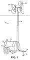
- Figure 1 shows an exemplary mobile light tower 10 which has a two wheeled trailer 11, a towing hitch 12 and three jacks 13 to support it when stationary. One of the jacks is hidden in Figure 1 .
- a retractable telescopic boom 14 is mounted on the trailer 11 so as to be upstanding when in use as shown in Figure 1 .
- a set of four high intensity lamps 15, such as metal halide lamps, are mounted at the top end of the boom 14 as shown in Figure 1 .
- a housing 16 on the trailer 11 has an opening 17 (see Figure 2 ) which is closed by a hinged cover 18 and which provides access to the interior of the housing 16 when that cover 18 is open.
- FIG. 2 shows the cover 18 open to reveal a two-stroke internal combustion engine 19 and an alternator assembly 21 within the housing 16.
- the alternator assembly 21 is an axial flux machine having a rotor and a stator.
- the rotor is drivingly coupled to the rotary output drive shaft of the engine 19 in place of the usual engine flywheel and acts as the flywheel of the engine 19.
- a battery 22 for use in starting the engine 16 is also provided in the housing 18.
- Any other suitable form of rotary prime mover such as a single stroke or a three stroke internal combustion engine, may be used to drive the alternator assembly 21 in place of the two stroke internal combustion engine 19.
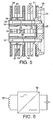
- FIGS 3 to 5 show the rotor 23 and stator 24 of one form of the alternator assembly 21.
- the rotor 23 is formed of three rotor discs 25, 26, 27 which are mounted coaxially.
- the rotor disc 25 has a hub portion 28 and an annular disc portion 29 which projects radially outwardly from the hub portion 28.
- the rotor discs 26 and 27 are annular and are each mounted on a generally tubular hub member 31 which is fastened coaxially to the hub portion 28 of the rotor disc 25 by a circular array of setscrews 32.
- the generally tubular hub member 28 comprises two circular arrays of axially extending circumferentially spaced fingers 33 and 34 which are interconnected by a substantially medial annular portion 35.
- the outside diameter of the circular array of fingers 33 which extend towards and into contact with the hub portion 28 of the rotor disc 25, is less than that of the circular array of fingers 34 which extend away from the rotor disc 25.
- the substantially medial annular portion 35 forms an annular shoulder 36 adjacent to its junction with the smaller diameter circular array of fingers 33.
- the annular rotor disc 26 is seated on the annular shoulder 36 and is fastened to the generally tubular hub member 31 by a circular array of setscrews 37 which extend through the substantially medial annular portion 35 and which are each screwed into a respective one of the larger diameter circular array of axially extending fingers 34.
- a circular array of arcuate shoulders 38 are formed in the ends of the larger diameter circular array of fingers 34 that are remote from the rotor disc 25.
- the annular rotor disc 27 is seated on the annular array of arcuate shoulders 38 and fastened to the generally tubular hub member 31 by a circular array of setscrews 39 which are each screwed into a respective one of
- the stator 24 includes a cylindrical outer casing 41 (see Figure 2 ) in which two pairs of annular stator cores 42 and 43 are mounted coaxially, one pair, 42, being between the pair of rotor discs 25 and 26 and the other pair, 43, being between the pair of rotor discs 26 and 27 as shown in Figure 5 .
- the generally tubular hub member 31 extends through the central aperture of the two pairs of annular stator cores 42 and 43.
- the means of mounting the pairs of annular stator cores 42 and 43 in the cylindrical casing 41 are not shown, but conveniently such means may include an annular support member of a non-ferrous material for each pair.
- Each support member may be in the form of a spider which includes an annular base portion and a plurality of arms, say six arms, which project radially outwards from the annular base portion.
- the annular base portion of each spider would be positioned between the annular cores of the respective pair 42, 43 so that the arms project radially outwards beyond the radially outer periphery of the annular cores of the respective pair 42, 43.
- the annular cores of the respective pair 42, 43 would be attached to the annular base portion of the spider, say by bonding or by the application of adhesive tape.
- the outer end portions of the arms would be fixed to the cylindrical casing 41 by suitable fixing means. It is to be understood that the pairs of stator cores 42 and 43 are insulated one from the other.
- Each annular stator core is an annular disc of ferromagnetic material.
- Each pair 42, 43 of annular stator cores is encased in a hollow annular cover 44 of plastics material which is a winding carrier and which is shown in Figures 3 and 4 .
- the form of each of the hollow annular covers 44 conveniently is substantially similar to that of the two part moulding 34 of an electrically insulating plastics material which has been described and illustrated in our International patent publication WO 02/089292 .
- each two part hollow annular cover 44 is formed of two similar annular parts which are interlocked at their radially inner and outer peripheral edges.
- the resultant hollow annular cover 44 has radially inner and outer annular support portions which are joined together on either side of the respective pair of annular cores 42, 43 of ferromagnetic material by a respective circular array of spaced radial ribs 45 which extend across the respective juxtaposed radial face of the adjacent annular core which is encased in the hollow annular cover 44.
- the radially inner annular support portions are hidden in Figure 3 and 4 but the radially outer annular support portions are visible at 46.
- the spaced radial ribs 45 form open ended radial passages 47 for electrical phase windings 48 which are wound around the respective pair of annular cores 42, 43 and annular winding cover 44 so that they extend around opposed faces of the inner annular support portion and the outer annular support portion 46 when the respective pair of annular cores 42, 43 is encased in the hollow annular cover 44 and is mounted in the cylindrical casing 41.
- Each radial rib 45 of each annular winding cover 44 projects radially beyond the respective radially outer annular support portion 46.
- the radial ribs 45 are tapered radially inwardly so that each open ended radial passage 47 is substantially parallel sided.
- Each radial rib 45 projects radially inwards beyond the respective radially inner ring portion, as can be seen in Figure 3 .
- the open ended radial passages 47 receive stator windings 48 which are torodially wound around each of the two pairs of annular stator cores 42 and 43 that are each encased in the respective annular cover 44.
- the windings 48 on each of the two pairs of stator cores 42 and 43 are insulated one from the other and are arranged as a two phase winding system. Also each winding 48 has a large number of turns so that it has a high impedance.
- Each turn of the stator windings 48 is led through an open ended passage 47 of the respective annular cover 44, across the outer periphery of the respective pairs of annular stator cores 42, 43, along the respective open ended passage 47 on the other side of the respective pair of annular stator cores 42, 43 and back through the central aperture of the respective pairs of annular stator cores 42, 43.
- Each phase of the pair of two phase windings 48 on each of the two annular winding covers 44 within which the respective pair of annular stator cores 42 and 43 are encased is connected to a respective output terminal, each of the four output terminals being connected to a respective one of the four high energy lamps 15 which are to be excited by operation of the alternator assembly 21.
- Each single annular stator core may be used instead of each pair 42, 43 of annular stator cores.
- Each single annular stator core would be encased within the respective hollow annular cover 44 and would be mounted within the cylindrical outer casing 41 by suitable mounting means.
- a circular array of alternately polarised permanent magnets 51, 52, 53 and 54 is mounted on each face on each of the three rotor components 25, 26 and 27 that faces the adjacent annular core 42, 43.
- the configuration of each rotor component face on which a respective circular array of permanent magnets 51-54 is mounted and the means by which those magnets 51-54 are mounted on that face may be as is described and illustrated in our International patent publication No. WO 02/056443 or preferably as described and illustrated in our European patent application No. 04254526.9 , priority British patent application No. 0317633.6 filed 26 July 2003 .
- Each of the permanent magnets 51 to 54 establishes an excitation magnetic field.
- each of the excitation magnetic fields links with the stator windings 48 that are wound on the respective pair of annular stator cores 42, 43 that the respective permanent magnets 51-54 face so that an emf is induced in those windings 48. That emf is fed to the respective output terminal as an output voltage for energizing the respective high energy lamp 15.
- the stator windings 48 are toroidally wound in pairs on each pair of annular stator cores 42, 43 as a two phase winding, each insulated from the other, so that the mutual inductance between the phases on each pair of annular stator cores 42, 43 is zero. Electrically speaking, this is due to their perpendicular alignment in space, so that the field induced in the respective stator cores 42, 43 by current flow in one of the windings of the respective pair of windings 48 lags the field induced in the respective stator cores 42, 43 by current flow in the other winding of the respective pair of windings 48 by 90°.
- the mutual inductance M between the phases of such a two phase winding system is proportional to the cosine of 90°C which is zero.
- the alternator assembly 21 shown in Figures 3 to 5 may be provided with at least one auxiliary coil in which an emf would be generated by rotation of the rotor 23.
- the emf generated in the auxiliary coil or coils would be used to charge the battery 22 so that there would be no need to provide a separate engine driven alternator for that purpose as is customary.
- the or each such an auxiliary coil would be wound on a respective one of the annular covers 44 alongside a group of turns of the stator windings 48 between a juxtaposed pair of the radial ribs 45.
- Figure 6 shows the output of such an auxiliary coil 55 would be connected to an input of an AC/DC convertor 56 which has positive and negative output terminals which are connected to the positive and negative terminals of the battery 22.
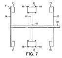
- Figures 7 and 8 show another form of alternator assembly 21 which has a rotor 61 and an annular stator core 62 which has a central aperture 63.
- the rotor 61 is formed of two similar rotor discs 64 and 65 which are mounted coaxially, one at either end of an axle 66.
- the axle 66 extends through the central aperture 63 of the annular stator core 62 so that the annular stator core 62 is between the rotor discs 64 and 65.
- the annular stator core 62 which is formed of a ferromagnetic material, carries a circular array of an even number of teeth 67 which are formed of a ferrous metal and which each project towards the rotor discs 64 and 65.
- a stator winding 68, 69 is wound on the end face of each tooth 67 which faces the adjacent rotor disc 64, 65. Hence there are two stator windings 68 and 69 wound at opposite ends of each tooth 67. The turns of each stator winding 68, 69 extend around an axis which is substantially parallel to the axis of rotation of the rotor 61.
- Figure 8 shows that the stator windings 68 on the left hand side of the annular stator core 62, as seen in Figure 7 , are wound on 8 teeth 67 and are interconnected in a two-phase, 4-pole winding arrangement which has two inputs and two outputs.
- the stator windings 68 of one of the phases are shown with single headed arrows and the stator windings 68 of the other phase are shown with double headed arrows.
- the direction of the magnetic field induced in each tooth 67 by current flow in the windings 68 wound on that tooth 67 is indicated by either "x" or " ⁇ ".
- stator windings 68 of each phase that are directly connected to the respective input
- stator windings 68 on each of the teeth 67 are connected to the stator windings 68 on the next but one tooth 67 in the anti-clockwise direction as seen in Figure 8 so that, apart from the teeth 67 that are wound with stator windings 68 that are directly connected to the respective input or output, a tooth 67 wound with windings of one phase of the two phase winding arrangement is between a pair of teeth 67 wound with the windings 68 of the other phase of the two-phase winding arrangement.
- stator windings 69 on the right hand side of the annular stator core 62, as seen in Figure 8 , are interconnected similarly in another two-phase winding arrangement.
- the mutual inductance between the phases of either of the two-phase windings 68 and 69 on the stator core 62 is zero.
- windings 68 and 69 are wound on each tooth 67 so that the fields induced in each tooth 67 by current flow in the windings 68 and 69 wound thereon oppose one another and are on either side of a magnetic neutral at the centre of the respective tooth 67 so that the windings 68 and 69 on each of the teeth 67 are electromagnetically isolated from one another.
- Each tooth 67 and the annular stator core 62 may be separated into two parts by a layer of insulating material, which extends in a substantially diametral plane in the centre of the annular stator core 62, so that the two individual stator windings 68 and 69 wound on each tooth 67 are insulated one from the other, if necessary.
- Each rotor disc 64, 65 carries a circular array of alternately polarised permanent magnets 71, 72 on its face that faces the circular array of teeth 67 so that an air gap is formed between each tooth 67 and the magnets 71, 72 that it faces and such that rotation of the rotor 61 relative to the annular stator core 62 induces an emf in each phase of the windings 68 and 69 carried by the annular core 62.
- Each phase of the stator winding 68, 69 is connected to a respective output terminal of the alternator assembly 21 for connection to a respective high intensity lamp 15 which is to be energized by operation of the alternator assembly 21.
- each of the alternator assemblies 21 described above with reference to the accompanying drawings has substantial internal impedance characteristics. This is because the stator windings are wound with a large number of turns. Also they are arranged so as to avoid mutual coupling and thereby to enable individual lamp switching and, in the event of failure of a lamp, to provide for protection of the other lamps.
- alternator assemblies 21 in which this invention is embodied are operable so that each of the stator windings initially provides an output voltage sufficient to initiate conduction of the respective high intensity lamp 15 to which they are connected followed, due to the effect of the high impedance of the respective stator windings which limits the current supply to the respective lamp, by a lower sustaining output voltage which maintains current flow in the respective lamp after the initial conduction in the lamp 15.
- the alternator assembly 21 will be provided with as many stator windings as there are lamps to be energized. Where necessary, additional annular stator cores would be provided to carry the additional stator windings which, where necessary, would be wound in a two-phase winding arrangement on each annular stator core as described above.
- an alternator assembly in which this invention is embodied can be used to drive loads other than high intensity lamps.
Landscapes
- Engineering & Computer Science (AREA)
- Power Engineering (AREA)
- Synchronous Machinery (AREA)
- Permanent Magnet Type Synchronous Machine (AREA)
- Connection Of Motors, Electrical Generators, Mechanical Devices, And The Like (AREA)
- Iron Core Of Rotating Electric Machines (AREA)
Claims (21)
- Generatoranordnung bzw. -baugruppe, die einen Rotor, der Mittel zum Aufbauen eines Erregerfelds, und einen Stator mit einer Mehrzahl individueller bzw. einzelner Statorwicklungen daran bzw. darauf enthält, wobei eine für jede einer Mehrzahl von Ladungen ist, dadurch gekennzeichnet, dass der Stator wenigstens eine Statorkomponente mit wenigstens einem Paar der Statorwicklungen, die daran bzw. darauf in einer Zweiphasenwickelanordnungen gewickelt sind, umfasst, wodurch das Feld, das in die oder jede Statorkomponente durch einen Stromfluss in einer der Wicklungen des jeweiligen Paars induziert wird, dem Feld, das in die jeweilige Statorkomponente durch einen Stromfluss in der anderen Wicklung des jeweiligen Paars induziert wird, um 90° nacheilt, so dass im Wesentlichen keine gegenseitige Induktivität zwischen den an die oder jede Statorkomponente gewickelten Statorwicklungen aufgebaut wird.
- Generatoranordnung nach Anspruch 1, die eine Axialflussmaschine ist.
- Generatoranordnung nach Anspruch 1 oder Anspruch 2, wobei die einzelnen Statorwicklungen eine Wicklung enthalten, die jeder einer Mehrzahl von zu erregenden bzw. speisenden Lampen zugeordnet ist, wobei die Generatoranordnung betriebsfähig ist, so dass jede der zugeordneten Statorwicklungen eine Ausgangsspannung bereitstellt, die ausreichend ist, um ein Leiten der jeweiligen Lampe gefolgt von einer anhaltenden Ausgangsspannung einzuleiten bzw. zu initiieren, um den Stromfluss nach dem anfänglichen Leiten beizubehalten, wobei jede zugeordnete Statorwicklung so angeordnet ist, dass sie eine ausreichende Innenimpedanz innerhalb der Generatoranordnung nach dem Initiieren des Leitens erzeugt, um die Stromversorgung zu der jeweiligen Lampe zu beschränken.
- Generatoranordnung nach einem der Ansprüche 1 bis 3, wobei die Mittel zum Aufbauen eines Erregerfelds ein kreisförmiges Array aus abwechselnd polarisierten Permanentmagneten umfassen.
- Generatoranordnung nach Anspruch 3 oder Anspruch 4, wenn auf Anspruch 3 rückbezogen, wobei die Generatoranordnung zum Speisen von 2N-Lampen dient und der Stator separate N-Statorkomponenten enthält, wobei jede Statorkomponente ein jeweiliges Paar Statorwicklungen daran gewickelt aufweist.
- Generatoranordnung nach Anspruch 5, wenn auf Anspruch 4 rückbezogen, wobei die N-Statorkomponenten koaxial in einer Reihe getragen sind und der Rotor wenigstens (N-1) Rotorkomponenten enthält, die koaxial in einer Reihe zur Drehung einer zwischen jedem nebeneinander liegenden Paar Statorkomponenten getragen sind, wobei jede Rotorkomponente ein kreisförmiges Array der Permanentmagneten an der radialen Fläche trägt, die der benachbarten bzw. angrenzenden Statorkomponente zugewandt ist.
- Generatoranordnung nach Anspruch 6, wobei der Rotor (N+1) der Rotorkomponenten enthält, die jeweils ein kreisförmiges Array aus Permanentmagneten an einer Fläche tragen, die der benachbarten bzw. angrenzenden Statorkomponente zugewandt ist.
- Generatoranordnung nach Anspruch 6 oder Anspruch 7, wobei die Rotorkomponenten eine Rotorscheibe, die einen einstückigen bzw. integralen Nabenabschnitt und einen sich radial erstreckenden Scheibenabschnitt aufweist, ein im Wesentlichen rohrförmiges Glied, das so angeordnet ist, dass es sich im Wesentlichen koaxial mit dem integralen Nabenabschnitt dreht, und zwei andere Rotorscheiben enthält, die ringförmig sind und an dem im Allgemeinen rohrförmigen Glied angeordnet sind.
- Generatoranordnung nach Anspruch 8, wobei die radial äußere Oberfläche des im Allgemeinen rohrförmigen Glieds einen Abschnitt mit größerem Durchmesser und einen Abschnitt mit kleinerem Durchmesser aufweist, welcher der Abschnitt des im Allgemeinen rohrförmigen Glieds ist, der an dem integralen Nabenabschnitt der einen Rotorscheibe fixiert bzw. befestigt ist, wobei die anderen Rotorscheiben in jeweiligen ringförmigen Schulteranordnungen plaziert sind, die an jedem Ende des Abschnitts mit größerem Durchmesser gebildet sind.
- Generatoranordnung nach Anspruch 8 oder Anspruch 9, wobei die eine Rotorscheibe angepasst ist, mit einer ausgangsseitigen Antriebswelle einer Rotationskraftmaschine gekoppelt zu sein und massiv ist im Vergleich zu den beiden anderen Rotorscheiben, so dass sie als ein Schwungrad der Kraftmaschine fungiert.
- Generatoranordnung nach Anspruch 2 oder Anspruch 3, wenn auf Anspruch 2 rückbezogen, wobei der Rotor der Axialflussmaschine eine Rotorscheibe enthält und die wenigstens eine Statorkomponente der Axialflussmaschine einen Statorkern enthält, wobei die Rotorscheibe aus einem Eisenmetall gebildet ist und drehbar um eine Achse relativ zu dem Statorkern angelenkt ist, von dem sie in der Richtung der Drehachse beabstandet ist, wobei der Statorkern ein kreisförmiges Array aus Zähnen aufweist, die aus einem Eisenmetall gebildet sind und die zu der Rotorscheibe hin ragen, so dass ein Luftspalt zwischen der Rotorscheibe und den Oberflächen der Zähne gebildet ist, die ihr am nächsten sind, wobei eine jeweilige der einzelnen Statorwicklungen an jeden der Zähne gewickelt ist, so dass das Erregerfeld, das durch die Mittel aufgebaut wird, die durch den Rotor getragen sind, eine Verbindung mit den einzelnen Statorwicklungen herstellt, um eine EMK in die einzelnen Statorwicklungen zu induzieren, wobei abwechselnde Zähne oder abwechselnde Gruppen von nebeneinander liegenden Zähnen mit einer unterschiedlichen der beiden Statorwicklungen der Zweiphasenwicklungsanordnung gewickelt sind, so dass ein Zahn oder eine Gruppe von Zähnen, die/der mit den Wicklungen einer Phase gewickelt ist/sind, zwischen ein Paar Zähne oder einer Gruppe von Zähnen ist/sind, die mit den Wicklungen der anderen Phase gewickelt sind.
- Generatoranordnung nach Anspruch 11, wobei die Rotorscheibe eine von zwei Rotorscheiben ist, die an einer gemeinsamen Komponente zur gemeinsamen Drehung um die Achse montiert sind, und der Statorkern ringförmig mit einer zentralen Öffnung ist und zwischen den beiden Rotorscheiben positioniert ist, die beide ähnlich ausgerichtet sind, wobei die Zähne von dem ringförmigen Statorkern zu jeder der Rotorscheiben hin ragen und sich die gemeinsame Komponente durch die zentrale Öffnung erstreckt, wobei es eine jeweilige Zweiphasenwicklungsanordnung gibt, die ähnlich an die Zähne an jedem Ende gewickelt ist, so dass ein Zahn oder eine Gruppe nebeneinanderliegender Zähne, die mit den Wicklungen einer Phase jedes des Paars von Zweiphasenwicklungsanordnungen zwischen einem Paar Zähne oder einer Gruppe von Zähnen ist, die mit den Wicklungen der anderen Phase des Paars von Zweiphasenwicklungsanordnungen gewickelt ist, wobei die Wicklungen an die Zähne gewickelt sind, so dass die Felder, die durch einen Stromfluss in den daran gewickelten Wicklungen induziert werden, einander entgegengesetzt sind, so dass die Wicklungen an jedem Zahn elektromagnetisch voneinander isoliert sind.
- Generatoranordnung nach Anspruch 11 oder 12, wobei jeder Zahn von den anderen Zähnen an dem Statorkern isoliert ist.
- Generatoranordnung nach einem der Ansprüche 11 bis 13, wobei jede der einzelnen Statorwicklungen, die an einen Zahn gewickelt sind, auf eine Spule gewickelt ist, die auf den jeweiligen Zahn gepasst ist.
- Generatoranordnung nach einem der Ansprüche 11 bis 13, wobei jede der einzelnen Statorwicklungen, die auf die Zähne des Statorkerns gewickelt sind, um eine Gruppe von zwei oder mehr nebeneinander liegenden Zähnen Flyergewickelt ist.
- Generatoranordnung nach einem der Ansprüche 11 bis 15, wobei der Rotor angepasst ist, mit einer ausgangsseitigen Antriebswelle einer Rotationskraftmaschine durch eine massive Rotorscheibe gekoppelt zu sein, die als ein Schwungrad der Kraftmaschine fungiert.
- Generatoranordnung nach Anspruch 10 oder Anspruch 16, wobei die Rotationskraftmaschine eine Einhub-, Zweihub- oder Dreihub-Verbrennungskraftmaschine ist und die massive Rotorscheibe eine unausgewuchtete Rotationskomponente ist, wobei der Grad der Unwucht so gewählt ist, dass, wenn die massive Rotorscheibe mit der ausgangsseitigen Antriebswelle der Zweihub- oder Dreihub-Verbrennungskraftmaschine gekoppelt ist, die resultierende Rotationsanordnung im Wesentlichen ausgewuchtet ist.
- Generatoranordnung nach Anspruch 17 in Kombination mit einer Einhub-, Zweihub- oder Dreihub-Verbrennungskraftmaschine, wobei die massive Rotorscheibe mit der ausgangsseitigen Antriebswelle des Motors gekoppelt ist.
- Transportabler bzw. tragbarer Lichttower bzw. -mast, der eine Generatoranordnung nach einem der Ansprüche 16 bis 18 enthält, wenn auf Anspruch 3 rückbezogen, wobei jede Wicklung der Generatoranordnung mit einer jeweiligen Lampe des Lichttowers verbunden ist, so dass die Lampen gespeist werden, wenn die Generatoranordnung durch die Rotationskraftmaschine angetrieben wird.
- Vorrichtung nach einem der Ansprüche 2 bis 19, wobei die Generatoranordnung wenigstens eine Hilfsspule enthält, die an den Stator gewickelt ist und die von den Statorwicklungen isoliert ist, wobei die Hilfsspule Enden aufweist, durch die sie mit einem Eingang von Wechselstrom/Gleichstrom-Wandlermitteln, die einen Gleichstromausgang aufweisen, verbunden ist, der zur Verbindung mit Anschlüssen einer elektrischen Batterie dient, die zum Betrieb einer Kraftmaschine vorgesehen ist, die antriebsmäßig mit der Generatoranordnung zu koppeln ist, wobei die Anordnung derart ist, dass, wenn die Generatoranordnung durch die Kraftmaschine angetrieben wird, die Batterie durch den Ausgang der wenigstens einen Hilfsspule geladen wird, die durch die Wechselstrom/Gleichstrom-Wandlermittel umgewandelt wird.
- Verwendung der Vorrichtung nach einem der Ansprüche 3 bis 19, um Lampen eines transportablen Lichttowers bzw. -masts zu speisen.
Applications Claiming Priority (2)
| Application Number | Priority Date | Filing Date | Title |
|---|---|---|---|
| GBGB0320559.8A GB0320559D0 (en) | 2003-09-02 | 2003-09-02 | An alternator assembly |
| PCT/GB2004/003760 WO2005022725A1 (en) | 2003-09-02 | 2004-09-02 | An alternator assembly |
Publications (2)
| Publication Number | Publication Date |
|---|---|
| EP1661232A1 EP1661232A1 (de) | 2006-05-31 |
| EP1661232B1 true EP1661232B1 (de) | 2008-07-30 |
Family
ID=28686789
Family Applications (1)
| Application Number | Title | Priority Date | Filing Date |
|---|---|---|---|
| EP04768307A Expired - Lifetime EP1661232B1 (de) | 2003-09-02 | 2004-09-02 | Generatorbaugruppe |
Country Status (7)
| Country | Link |
|---|---|
| EP (1) | EP1661232B1 (de) |
| JP (1) | JP4634383B2 (de) |
| CN (1) | CN100566091C (de) |
| AT (1) | ATE403256T1 (de) |
| DE (1) | DE602004015477D1 (de) |
| GB (1) | GB0320559D0 (de) |
| WO (1) | WO2005022725A1 (de) |
Families Citing this family (18)
| Publication number | Priority date | Publication date | Assignee | Title |
|---|---|---|---|---|
| JP2009072009A (ja) * | 2007-09-14 | 2009-04-02 | Shin Etsu Chem Co Ltd | 永久磁石回転機 |
| GB0813032D0 (en) * | 2008-07-16 | 2008-08-20 | Cummins Generator Technologies | Axial flux machine |
| JP5135111B2 (ja) * | 2008-08-04 | 2013-01-30 | 富士重工業株式会社 | モータジェネレータおよび汎用エンジン |
| CN101699712B (zh) * | 2009-11-11 | 2011-06-08 | 泰豪科技股份有限公司 | 一种二相中频整流发电机 |
| KR101258775B1 (ko) | 2011-10-10 | 2013-04-29 | 최호식 | 도체의 전기저항을 이용한 교류 발생장치 |
| CN102545412A (zh) * | 2011-12-19 | 2012-07-04 | 上海电机学院 | 高效率、大转矩盘式开关磁阻电机 |
| CN102624172B (zh) * | 2012-03-09 | 2015-04-15 | 东南大学 | 一种飞轮脉冲永磁电机及工作方法 |
| CN104682641A (zh) * | 2015-03-04 | 2015-06-03 | 广东威灵电机制造有限公司 | 双定子轴向磁场电机 |
| US10270305B2 (en) * | 2015-12-07 | 2019-04-23 | Hamilton Sundstrand Corporation | Motor-generator with multiple stator windings |
| CN105490481B (zh) * | 2015-12-25 | 2018-10-26 | 华中科技大学 | 一种高转矩密度多盘-多气隙轴向磁通磁场调制永磁电机 |
| CN108667253B (zh) * | 2017-10-25 | 2019-11-19 | 永康市杰创工业产品设计有限公司 | 一种汽车盘式轮毂永磁电机及其安装工艺 |
| WO2019213949A1 (en) * | 2018-05-11 | 2019-11-14 | Schaeffler Technologies AG & Co. KG | Multiple-rotor disc-type generator for railway vehicle, railway vehicle and method for mounting the generator |
| CN109980880A (zh) * | 2019-04-17 | 2019-07-05 | 哈尔滨理工大学 | 三相分离定子无轭模块化轴向磁通永磁盘式轮毂直驱电机 |
| US11502564B2 (en) * | 2020-04-03 | 2022-11-15 | Mitsubishi Electric Research Laboratories, Inc. | Multi-layer axial and radial flux vernier permanent magnet motor |
| CN111697784B (zh) * | 2020-05-21 | 2021-08-06 | 南京航空航天大学 | 一种主动制动并回收能量的非充气车轮 |
| US11913611B2 (en) | 2021-10-15 | 2024-02-27 | Briggs & Stratton, Llc | Hybrid light tower |
| US11959616B2 (en) | 2021-10-15 | 2024-04-16 | Briggs & Stratton, Llc | Battery powered light tower |
| CZ2022497A3 (cs) * | 2022-11-28 | 2024-03-27 | LIVING CZ spol. s r.o. | Bezkartáčový stejnosměrný elektromotor |
Family Cites Families (8)
| Publication number | Priority date | Publication date | Assignee | Title |
|---|---|---|---|---|
| GB730512A (en) * | 1953-05-28 | 1955-05-25 | Croydon Engineering Company Lt | Improvements in or relating to alternators |
| FR2548844A1 (fr) * | 1983-07-07 | 1985-01-11 | Labinal | Perfectionnement aux generateurs autonomes a plusieurs sorties |
| US4591763A (en) * | 1983-07-14 | 1986-05-27 | Wanasz Michael J | Electric generator system for portable floodlighting equipment |
| US4996457A (en) * | 1990-03-28 | 1991-02-26 | The United States Of America As Represented By The United States Department Of Energy | Ultra-high speed permanent magnet axial gap alternator with multiple stators |
| US5334899A (en) * | 1991-09-30 | 1994-08-02 | Dymytro Skybyk | Polyphase brushless DC and AC synchronous machines |
| US5764036A (en) * | 1995-03-08 | 1998-06-09 | Sundstrand Corporation | Multiple output decoupled synchronous generator and electrical system employing same |
| JPH09233790A (ja) * | 1996-02-27 | 1997-09-05 | Kokusan Denki Co Ltd | 内燃機関駆動放電灯点灯用発電機及び放電灯点灯装置 |
| DE1159780T1 (de) * | 1999-02-10 | 2002-08-22 | Multipolgenerator Aps, Roskilde | Mehrpoliger elektrischer motor/generator mit axialem magnetischen fluss. |
-
2003
- 2003-09-02 GB GBGB0320559.8A patent/GB0320559D0/en not_active Ceased
-
2004
- 2004-09-02 CN CNB2004800251589A patent/CN100566091C/zh not_active Expired - Fee Related
- 2004-09-02 JP JP2006525878A patent/JP4634383B2/ja not_active Expired - Fee Related
- 2004-09-02 AT AT04768307T patent/ATE403256T1/de not_active IP Right Cessation
- 2004-09-02 DE DE602004015477T patent/DE602004015477D1/de not_active Expired - Lifetime
- 2004-09-02 EP EP04768307A patent/EP1661232B1/de not_active Expired - Lifetime
- 2004-09-02 WO PCT/GB2004/003760 patent/WO2005022725A1/en not_active Ceased
Also Published As
| Publication number | Publication date |
|---|---|
| WO2005022725A1 (en) | 2005-03-10 |
| CN1846341A (zh) | 2006-10-11 |
| JP2007504798A (ja) | 2007-03-01 |
| ATE403256T1 (de) | 2008-08-15 |
| GB0320559D0 (en) | 2003-10-01 |
| EP1661232A1 (de) | 2006-05-31 |
| JP4634383B2 (ja) | 2011-02-16 |
| CN100566091C (zh) | 2009-12-02 |
| DE602004015477D1 (de) | 2008-09-11 |
Similar Documents
| Publication | Publication Date | Title |
|---|---|---|
| US7701101B2 (en) | Alternator assembly | |
| EP1661232B1 (de) | Generatorbaugruppe | |
| US5783893A (en) | Multiple stator, single shaft electric machine | |
| US7078840B2 (en) | Brushless rotary electric machine having tandem rotary cores | |
| US6177746B1 (en) | Low inductance electrical machine | |
| US6753637B2 (en) | Exciter rotor assembly | |
| US6097124A (en) | Hybrid permanent magnet/homopolar generator and motor | |
| JPS61251459A (ja) | 永久磁石可変磁気抵抗発電機 | |
| JPS62147936A (ja) | 電気回転装置 | |
| CN101772876A (zh) | 带有混合励磁转子的电机 | |
| US9935532B2 (en) | Double-rotor type electrical rotating machines | |
| KR20180081672A (ko) | 모터와 알터네이터를 융합한 구동기계 | |
| US3140413A (en) | Inductor alternator | |
| RU2302692C9 (ru) | Электромеханический преобразователь | |
| CN104247232B (zh) | 电机 | |
| CN110504810A (zh) | 并联磁路混合励磁磁阻电机系统 | |
| CA2638516A1 (en) | An electricity generator and an installation comprising a lighting tower powered by such a generator | |
| KR100569502B1 (ko) | 2중 배면 권선 구조를 가진 모터 스테이터 | |
| US12476525B2 (en) | Axial flux electric machine with non-axisymmetric stators | |
| US20080067883A1 (en) | Generator and/or motor assembly | |
| US4757225A (en) | Dual stack tachometer/generator | |
| RU95107317A (ru) | Генератор электрической энергии | |
| JPH0715332Y2 (ja) | 車両用発電機 | |
| WO2009051514A1 (fr) | Convertisseur électromécanique | |
| KR100866871B1 (ko) | 유도전동기 |
Legal Events
| Date | Code | Title | Description |
|---|---|---|---|
| PUAI | Public reference made under article 153(3) epc to a published international application that has entered the european phase |
Free format text: ORIGINAL CODE: 0009012 |
|
| 17P | Request for examination filed |
Effective date: 20060214 |
|
| AK | Designated contracting states |
Kind code of ref document: A1 Designated state(s): AT BE BG CH CY CZ DE DK EE ES FI FR GB GR HU IE IT LI LU MC NL PL PT RO SE SI SK TR |
|
| DAX | Request for extension of the european patent (deleted) | ||
| RAP1 | Party data changed (applicant data changed or rights of an application transferred) |
Owner name: CUMMINS GENERATOR TECHNOLOGIES LIMITED |
|
| GRAC | Information related to communication of intention to grant a patent modified |
Free format text: ORIGINAL CODE: EPIDOSCIGR1 |
|
| GRAP | Despatch of communication of intention to grant a patent |
Free format text: ORIGINAL CODE: EPIDOSNIGR1 |
|
| GRAS | Grant fee paid |
Free format text: ORIGINAL CODE: EPIDOSNIGR3 |
|
| GRAA | (expected) grant |
Free format text: ORIGINAL CODE: 0009210 |
|
| AK | Designated contracting states |
Kind code of ref document: B1 Designated state(s): AT BE BG CH CY CZ DE DK EE ES FI FR GB GR HU IE IT LI LU MC NL PL PT RO SE SI SK TR |
|
| REG | Reference to a national code |
Ref country code: GB Ref legal event code: FG4D |
|
| REG | Reference to a national code |
Ref country code: CH Ref legal event code: EP |
|
| REF | Corresponds to: |
Ref document number: 602004015477 Country of ref document: DE Date of ref document: 20080911 Kind code of ref document: P |
|
| REG | Reference to a national code |
Ref country code: IE Ref legal event code: FG4D |
|
| PG25 | Lapsed in a contracting state [announced via postgrant information from national office to epo] |
Ref country code: ES Free format text: LAPSE BECAUSE OF FAILURE TO SUBMIT A TRANSLATION OF THE DESCRIPTION OR TO PAY THE FEE WITHIN THE PRESCRIBED TIME-LIMIT Effective date: 20081110 Ref country code: NL Free format text: LAPSE BECAUSE OF FAILURE TO SUBMIT A TRANSLATION OF THE DESCRIPTION OR TO PAY THE FEE WITHIN THE PRESCRIBED TIME-LIMIT Effective date: 20080730 Ref country code: PT Free format text: LAPSE BECAUSE OF FAILURE TO SUBMIT A TRANSLATION OF THE DESCRIPTION OR TO PAY THE FEE WITHIN THE PRESCRIBED TIME-LIMIT Effective date: 20081230 |
|
| PG25 | Lapsed in a contracting state [announced via postgrant information from national office to epo] |
Ref country code: FI Free format text: LAPSE BECAUSE OF FAILURE TO SUBMIT A TRANSLATION OF THE DESCRIPTION OR TO PAY THE FEE WITHIN THE PRESCRIBED TIME-LIMIT Effective date: 20080730 Ref country code: BG Free format text: LAPSE BECAUSE OF FAILURE TO SUBMIT A TRANSLATION OF THE DESCRIPTION OR TO PAY THE FEE WITHIN THE PRESCRIBED TIME-LIMIT Effective date: 20081030 Ref country code: SI Free format text: LAPSE BECAUSE OF FAILURE TO SUBMIT A TRANSLATION OF THE DESCRIPTION OR TO PAY THE FEE WITHIN THE PRESCRIBED TIME-LIMIT Effective date: 20080730 Ref country code: AT Free format text: LAPSE BECAUSE OF FAILURE TO SUBMIT A TRANSLATION OF THE DESCRIPTION OR TO PAY THE FEE WITHIN THE PRESCRIBED TIME-LIMIT Effective date: 20080730 |
|
| PG25 | Lapsed in a contracting state [announced via postgrant information from national office to epo] |
Ref country code: BE Free format text: LAPSE BECAUSE OF FAILURE TO SUBMIT A TRANSLATION OF THE DESCRIPTION OR TO PAY THE FEE WITHIN THE PRESCRIBED TIME-LIMIT Effective date: 20080730 |
|
| PG25 | Lapsed in a contracting state [announced via postgrant information from national office to epo] |
Ref country code: EE Free format text: LAPSE BECAUSE OF FAILURE TO SUBMIT A TRANSLATION OF THE DESCRIPTION OR TO PAY THE FEE WITHIN THE PRESCRIBED TIME-LIMIT Effective date: 20080730 Ref country code: DK Free format text: LAPSE BECAUSE OF FAILURE TO SUBMIT A TRANSLATION OF THE DESCRIPTION OR TO PAY THE FEE WITHIN THE PRESCRIBED TIME-LIMIT Effective date: 20080730 Ref country code: MC Free format text: LAPSE BECAUSE OF NON-PAYMENT OF DUE FEES Effective date: 20080930 |
|
| REG | Reference to a national code |
Ref country code: CH Ref legal event code: PL |
|
| PG25 | Lapsed in a contracting state [announced via postgrant information from national office to epo] |
Ref country code: CZ Free format text: LAPSE BECAUSE OF FAILURE TO SUBMIT A TRANSLATION OF THE DESCRIPTION OR TO PAY THE FEE WITHIN THE PRESCRIBED TIME-LIMIT Effective date: 20080730 Ref country code: RO Free format text: LAPSE BECAUSE OF FAILURE TO SUBMIT A TRANSLATION OF THE DESCRIPTION OR TO PAY THE FEE WITHIN THE PRESCRIBED TIME-LIMIT Effective date: 20080730 Ref country code: SK Free format text: LAPSE BECAUSE OF FAILURE TO SUBMIT A TRANSLATION OF THE DESCRIPTION OR TO PAY THE FEE WITHIN THE PRESCRIBED TIME-LIMIT Effective date: 20080730 |
|
| PLBE | No opposition filed within time limit |
Free format text: ORIGINAL CODE: 0009261 |
|
| STAA | Information on the status of an ep patent application or granted ep patent |
Free format text: STATUS: NO OPPOSITION FILED WITHIN TIME LIMIT |
|
| REG | Reference to a national code |
Ref country code: IE Ref legal event code: MM4A |
|
| 26N | No opposition filed |
Effective date: 20090506 |
|
| PG25 | Lapsed in a contracting state [announced via postgrant information from national office to epo] |
Ref country code: IE Free format text: LAPSE BECAUSE OF NON-PAYMENT OF DUE FEES Effective date: 20080902 |
|
| PG25 | Lapsed in a contracting state [announced via postgrant information from national office to epo] |
Ref country code: IT Free format text: LAPSE BECAUSE OF FAILURE TO SUBMIT A TRANSLATION OF THE DESCRIPTION OR TO PAY THE FEE WITHIN THE PRESCRIBED TIME-LIMIT Effective date: 20080730 |
|
| PG25 | Lapsed in a contracting state [announced via postgrant information from national office to epo] |
Ref country code: LI Free format text: LAPSE BECAUSE OF NON-PAYMENT OF DUE FEES Effective date: 20080930 Ref country code: CH Free format text: LAPSE BECAUSE OF NON-PAYMENT OF DUE FEES Effective date: 20080930 |
|
| PG25 | Lapsed in a contracting state [announced via postgrant information from national office to epo] |
Ref country code: SE Free format text: LAPSE BECAUSE OF FAILURE TO SUBMIT A TRANSLATION OF THE DESCRIPTION OR TO PAY THE FEE WITHIN THE PRESCRIBED TIME-LIMIT Effective date: 20081030 |
|
| PG25 | Lapsed in a contracting state [announced via postgrant information from national office to epo] |
Ref country code: PL Free format text: LAPSE BECAUSE OF FAILURE TO SUBMIT A TRANSLATION OF THE DESCRIPTION OR TO PAY THE FEE WITHIN THE PRESCRIBED TIME-LIMIT Effective date: 20080730 |
|
| PG25 | Lapsed in a contracting state [announced via postgrant information from national office to epo] |
Ref country code: CY Free format text: LAPSE BECAUSE OF FAILURE TO SUBMIT A TRANSLATION OF THE DESCRIPTION OR TO PAY THE FEE WITHIN THE PRESCRIBED TIME-LIMIT Effective date: 20080730 Ref country code: HU Free format text: LAPSE BECAUSE OF FAILURE TO SUBMIT A TRANSLATION OF THE DESCRIPTION OR TO PAY THE FEE WITHIN THE PRESCRIBED TIME-LIMIT Effective date: 20090131 Ref country code: LU Free format text: LAPSE BECAUSE OF NON-PAYMENT OF DUE FEES Effective date: 20080902 |
|
| PG25 | Lapsed in a contracting state [announced via postgrant information from national office to epo] |
Ref country code: TR Free format text: LAPSE BECAUSE OF FAILURE TO SUBMIT A TRANSLATION OF THE DESCRIPTION OR TO PAY THE FEE WITHIN THE PRESCRIBED TIME-LIMIT Effective date: 20080730 |
|
| PG25 | Lapsed in a contracting state [announced via postgrant information from national office to epo] |
Ref country code: GR Free format text: LAPSE BECAUSE OF FAILURE TO SUBMIT A TRANSLATION OF THE DESCRIPTION OR TO PAY THE FEE WITHIN THE PRESCRIBED TIME-LIMIT Effective date: 20081031 |
|
| REG | Reference to a national code |
Ref country code: FR Ref legal event code: PLFP Year of fee payment: 13 |
|
| REG | Reference to a national code |
Ref country code: FR Ref legal event code: PLFP Year of fee payment: 14 |
|
| PGFP | Annual fee paid to national office [announced via postgrant information from national office to epo] |
Ref country code: FR Payment date: 20170925 Year of fee payment: 14 Ref country code: GB Payment date: 20170927 Year of fee payment: 14 |
|
| PGFP | Annual fee paid to national office [announced via postgrant information from national office to epo] |
Ref country code: DE Payment date: 20170927 Year of fee payment: 14 |
|
| REG | Reference to a national code |
Ref country code: DE Ref legal event code: R119 Ref document number: 602004015477 Country of ref document: DE |
|
| GBPC | Gb: european patent ceased through non-payment of renewal fee |
Effective date: 20180902 |
|
| PG25 | Lapsed in a contracting state [announced via postgrant information from national office to epo] |
Ref country code: DE Free format text: LAPSE BECAUSE OF NON-PAYMENT OF DUE FEES Effective date: 20190402 |
|
| PG25 | Lapsed in a contracting state [announced via postgrant information from national office to epo] |
Ref country code: FR Free format text: LAPSE BECAUSE OF NON-PAYMENT OF DUE FEES Effective date: 20180930 |
|
| PG25 | Lapsed in a contracting state [announced via postgrant information from national office to epo] |
Ref country code: GB Free format text: LAPSE BECAUSE OF NON-PAYMENT OF DUE FEES Effective date: 20180902 |
|
| P01 | Opt-out of the competence of the unified patent court (upc) registered |
Free format text: CASE NUMBER: UPC_APP_118471/2023 Effective date: 20230510 |