EP1659037A1 - Mechanism and method for lifting the hood or bonnet of a motor vehicle - Google Patents
Mechanism and method for lifting the hood or bonnet of a motor vehicle Download PDFInfo
- Publication number
- EP1659037A1 EP1659037A1 EP05077547A EP05077547A EP1659037A1 EP 1659037 A1 EP1659037 A1 EP 1659037A1 EP 05077547 A EP05077547 A EP 05077547A EP 05077547 A EP05077547 A EP 05077547A EP 1659037 A1 EP1659037 A1 EP 1659037A1
- Authority
- EP
- European Patent Office
- Prior art keywords
- pair
- members
- opening
- hood
- releasable hinge
- Prior art date
- Legal status (The legal status is an assumption and is not a legal conclusion. Google has not performed a legal analysis and makes no representation as to the accuracy of the status listed.)
- Granted
Links
Images


Classifications
-
- B—PERFORMING OPERATIONS; TRANSPORTING
- B60—VEHICLES IN GENERAL
- B60R—VEHICLES, VEHICLE FITTINGS, OR VEHICLE PARTS, NOT OTHERWISE PROVIDED FOR
- B60R21/00—Arrangements or fittings on vehicles for protecting or preventing injuries to occupants or pedestrians in case of accidents or other traffic risks
- B60R21/34—Protecting non-occupants of a vehicle, e.g. pedestrians
- B60R21/38—Protecting non-occupants of a vehicle, e.g. pedestrians using means for lifting bonnets
-
- B—PERFORMING OPERATIONS; TRANSPORTING
- B60—VEHICLES IN GENERAL
- B60R—VEHICLES, VEHICLE FITTINGS, OR VEHICLE PARTS, NOT OTHERWISE PROVIDED FOR
- B60R21/00—Arrangements or fittings on vehicles for protecting or preventing injuries to occupants or pedestrians in case of accidents or other traffic risks
- B60R21/34—Protecting non-occupants of a vehicle, e.g. pedestrians
-
- E—FIXED CONSTRUCTIONS
- E05—LOCKS; KEYS; WINDOW OR DOOR FITTINGS; SAFES
- E05Y—INDEXING SCHEME RELATING TO HINGES OR OTHER SUSPENSION DEVICES FOR DOORS, WINDOWS OR WINGS AND DEVICES FOR MOVING WINGS INTO OPEN OR CLOSED POSITION, CHECKS FOR WINGS AND WING FITTINGS NOT OTHERWISE PROVIDED FOR, CONCERNED WITH THE FUNCTIONING OF THE WING
- E05Y2900/00—Application of doors, windows, wings or fittings thereof
- E05Y2900/50—Application of doors, windows, wings or fittings thereof for vehicles
- E05Y2900/53—Application of doors, windows, wings or fittings thereof for vehicles characterised by the type of wing
- E05Y2900/531—Doors
-
- E—FIXED CONSTRUCTIONS
- E05—LOCKS; KEYS; WINDOW OR DOOR FITTINGS; SAFES
- E05Y—INDEXING SCHEME RELATING TO HINGES OR OTHER SUSPENSION DEVICES FOR DOORS, WINDOWS OR WINGS AND DEVICES FOR MOVING WINGS INTO OPEN OR CLOSED POSITION, CHECKS FOR WINGS AND WING FITTINGS NOT OTHERWISE PROVIDED FOR, CONCERNED WITH THE FUNCTIONING OF THE WING
- E05Y2900/00—Application of doors, windows, wings or fittings thereof
- E05Y2900/50—Application of doors, windows, wings or fittings thereof for vehicles
- E05Y2900/53—Application of doors, windows, wings or fittings thereof for vehicles characterised by the type of wing
- E05Y2900/536—Hoods
Abstract
Description
- This present invention relates generally to an apparatus and method for lifting a hood of a vehicle, more particularly the present invention is related to an apparatus and method for enabling the lifting of the hood in accordance with a predetermined activation event.
- Vehicles are typically provided with a front hood positioned at the forward end of the vehicle. The front hood is generally pivotally mounted to the vehicle frame by a pair of hinges disposed at the rearward end of the hood. The hinges allow the hood to pivot about the point of securement so that access may be provided to the engine compartment disposed below the hood. In a forward or head on collision the hood and front end of the vehicle will make first contact with the pedestrian. In the unfortunate event of a head on collision between a vehicle and a pedestrian, the pedestrian may impact upon a portion of the hood.
- Accordingly, it is desirable to provide a method and apparatus for use with and in anticipation of a collision with of a pedestrian with a portion of the hood.
- Disclosed herein is an apparatus and method for moving a portion of a vehicle hood away from a portion of the vehicle, the apparatus comprising at least one hinge for pivotally securing the hood to the vehicle, the hinge comprising: a base portion; a first member being either pivotally secured to the base portion or the hood at one end and releasably secured at its opposite end; a second member for moving the hood away from the vehicle when the first member has been released from either the hood or the base portion; and an activation device for providing a lifting force to the hood, wherein activation of the activation device releases the first member and provides a force for moving a portion of the hood away from the vehicle.
- In one exemplary embodiment, a releasable hinge for securing a hood to a vehicle is provided. The releasable hinge comprising: a base portion; a first member pivotally secured to the base portion at one end and a pair of members at the other end, a first one of the pair of members being pivotally secured to the base portion and a second one of the pair of members being pivotally secured to the first member at one end and the other end of the second one of the pair of members is configured to be pivotally secured to the hood; and a release mechanism for releasably securing the first member and the pair of members to the base portion, wherein the first member and the first one of the pair of members are able to pivot from a first position to a second position with respect to the base portion and the second one of the pair of members is able to pivot with respect to the first member and the first one of the pair of members after the release mechanism has been activated.
- In another exemplary embodiment, an activation system for a hood of a vehicle is provided. The activation system comprising: the activation system comprising: a pair of releasable hinges for pivotally securing the hood to the vehicle, each hinge of the pair of releasable hinges comprising: a base portion; a first member pivotally secured to the base portion at one end and a pair of members at the other end, a first one of the pair of members being pivotally secured to the base portion and a second one of the pair of members being pivotally secured to the first member at one end and the other end of the second one of the pair of members is configured to be pivotally secured to the hood; and a release mechanism for releasably securing the first member and the pair of members to the base portion, wherein the first member and the first one of the pair of members are able to pivot from a first position to a second position with respect to the base portion and the second one of the pair of members is able to pivot with respect to the first member and the first one of the pair of members after the release mechanism has been activated; and a lift mechanism for providing a lifting force to the hood, wherein activation of the lift mechanism moves a portion of the hood away from the vehicle when the release mechanism has been activated.
- In another exemplary embodiment, a releasable hinge and lift mechanism for securing a hood to a vehicle is provided. The hinge and lift mechanism comprising: a first member, having a first opening for rotatably receiving a portion of a pivot member of the hood therein, a second member slidably secured to the first member for movement between a first position and a second position, the second member having a second opening, which is configured to secure the portion of the pivot member in the first opening of the first member, when the second member is in the first position; an actuation device configured for providing an activation force to an actuating member slidably mounted to the second member, wherein the activation force causes the second member to first move to the second position, wherein the portion of the pivot member of the hood is no longer retained by the releasable hinge and thereafter the activation force causes the actuating member to slide from a non-activated position toward an activated position, wherein an actuating pin of the actuating member makes contact with a cam surface of a lift lever pivotally secured to the releasable hinge, wherein the lift lever is pivoted away from the releasable hinge.
- In another exemplary embodiment, a releasable hinge and lift mechanism for securing a hood to a vehicle is provided. The hinge and lift mechanism comprising: a first portion; a second portion, comprising a fixed portion and a slidable portion slidably mounted to the first portion for movement between a first position and a second position, the fixed portion comprising a first opening at one end and an elongated opening, the slidable portion comprising a second opening juxtaposed to the first opening when the slidable portion is in the first position; a first connecting member being pivotally secured to the first portion at one end and releaseably secured to the second portion at another end by a pivot pin that is rotatably secured within the first opening and the second opening when the slidable portion is in the first position; a second connecting member being pivotally secured to the first portion at one end and slidably secured to the second portion at another end by a pin that is slidably received within the elongated opening of the fixed portion and an elongated opening of the slidable portion; an actuation device for providing a force to move the slidable portion from the first position to the second position and thereafter move the pin of the second connecting member within the elongated openings of the fixed portion and the slidable portion to cause the second portion to move away from the first portion.
- In addition, a method for releasing and moving a portion of a hood of a vehicle is also provided. The method, comprising: determining if a pedestrian is about to contact the portion of the hood; activating a releasable hinge and lift mechanism for releasing another portion of the hood from the releasable hinge; and providing a force to the hood in order to provide an unoccupied space between the hood and a portion of the vehicle, wherein the releasable hinge and lift mechanism comprises: a first portion; a second portion, comprising a fixed portion and a slidable portion slidably mounted to the first portion for movement between a first position and a second position, the fixed portion comprising a first opening at one end and an elongated opening, the slidable portion comprising a second opening juxtaposed to the first opening when the slidable portion is in the first position; a first connecting member being pivotally secured to the first portion at one end and releaseably secured to the second portion at another end by a pivot pin that is rotatably secured within the first opening and the second opening when the slidable portion is in the first position; a second connecting member being pivotally secured to the first portion at one end and slidably secured to the second portion at another end by a pin that is slidably received within the elongated opening of the fixed portion and an elongated opening of the slidable portion; and an actuation device for providing a force to move the slidable portion from the first position to the second position and thereafter move the pin of the second connecting member within the elongated openings of the fixed portion and the slidable portion to cause the second portion to move away from the first portion.
- The above-described and other features of the present disclosure will be appreciated and understood by those skilled in the art from the following detailed description, drawings, and appended claims.
-
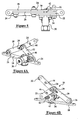
- Figure 1 is a view of a vehicle and a pedestrian illustrating the hood in a non-actuated position;
- Figure 2 is a view of a vehicle and a pedestrian illustrating the hood in an actuated position;
- Figure 3 is a perspective view of an exemplary embodiment of the present invention in a pre-activation position;
- Figure 4 is a perspective view of an exemplary embodiment of the present invention in a post activation position;
- Figure 5 is a top plan view of an exemplary embodiment of the present invention in a pre-activation position;
- Figures 6A-6D are perspective views of an exemplary embodiment of the present invention in a post activation position;
- Figures 7-9 illustrate various positions of an exemplary embodiment of the present invention;
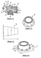
- Figures 10A-10B are perspective cross sectional views of an exemplary embodiment of the present invention in a pre-activation position;
- Figure 11 is a perspective cross sectional view of an exemplary embodiment of the present invention in a post-activation position;
- Figure 12 is a perspective view of an actuating mechanism of an exemplary embodiment of the present invention in a pre-activation position;
- Figure 13 is a side view of an actuating mechanism of an exemplary embodiment of the present invention in a post-activation position;
- Figure 14 is a perspective view of an actuating mechanism of an exemplary embodiment of the present invention in a pre-activation position;
- Figure 15 is a view along lines 15-15 of Figure 14;
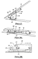
- Figure 16 is a perspective view of an actuating mechanism of an exemplary embodiment of the present invention in a post-activation position;
- Figure 17 is a view along lines 17-17 of Figure 16;
- Figures 18-20 are perspective views of an exemplary embodiment of the present invention;
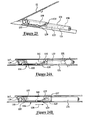
- Figures 21-23 are perspective views of an alternative exemplary embodiment of the present invention;
- Figures 24A and 24B are side views of an alternative exemplary embodiment of the present invention;
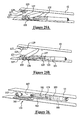
- Figures 25A and 25B are perspective views of an alternative exemplary embodiment of the present invention; and
- Figures 26-29B are perspective views of an alternative exemplary embodiment of the present invention.
- Disclosed herein is an apparatus and method for releasing and moving a portion of a hood of a vehicle. Referring now to Figure 1, a
vehicle 10 is illustrated.Vehicle 10 has ahood 12, which is typically located at a forward portion of the vehicle. Also shown in Figure 1 is apedestrian 14. Unfortunately and in the event of a collision between the vehicle and the pedestrian the pedestrian may impact the hood of the vehicle. - Figure 2 illustrates the vehicle with the hood repositioned by a
hood lift mechanism 15 in accordance with an exemplary embodiment of the present invention. In accordance with an exemplary embodiment of the present inventionhood lift mechanism 15 is coupled to acontroller 11, which is in electrical communication with asensor 17 that is configured and positioned to detect or predict an impact with the pedestrian. If an impending impact is detected, an activation signal is sent to the controller for activation of the hood lift mechanism or alternatively the signal from the sensor is sent directly to the hood lift mechanism, wherein the hood is lifted (Figure 2) prior to impact with the pedestrian. - In accordance with an exemplary embodiment, the sensor or sensor system of the vehicle may comprise an accelerometer or other equivalent device, in conjunction with a radar or distance sensing system in order to predict whether an impact is about to occur. In accordance with an
exemplary embodiment controller 11 comprises a sensor or sensing-and-diagnostic module that is adapted to detect an activation event wherein the occurrence of a threshold event will cause an activation signal to be generated and received by the hood lift mechanism, thereby causing the rear portion of the hood to be lifted. The detection of the threshold event is determined by one or more sensors, which are disposed about the vehicle in accordance with known technologies. Some exemplary sensors may include impact sensors at the front as well as other locations of the vehicle as well as accelerometers to detect massive decelerations. Thus, the activation signal controls activation of the hood lift mechanism. In an exemplary embodiment, the sensing-and-diagnostic module comprises a microprocessor, microcontroller or other equivalent processing device capable of executing commands of computer readable data or program for executing a control algorithm that controls the operation of the hood lift mechanism. In order to perform the prescribed functions and desired processing, as well as the computations therefore (e.g., the execution of fourier analysis algorithm(s), the control processes prescribed herein, and the like), the controller may include, but not be limited to, a processor(s), computer(s), memory, storage, register(s), timing, interrupt(s), communication interfaces, and input/output signal interfaces, as well as combinations comprising at least one of the foregoing. For example, the controller may include input signal filtering to enable accurate sampling and conversion or acquisitions of such signals from communications interfaces. As described above, exemplary embodiments of the present invention can be implemented through computer-implemented processes and apparatuses for practicing those processes. - Accordingly, exemplary embodiments of the present invention provide a method and apparatus for providing a hood hinge having a disengagement/release function and the lift mechanism that raises the rear edge of the hood during the detection of a pre-determined activation event. This lifting of the rear edge of the hood will provide additional clearance between hard object located under the hood and the hood itself. Thus, portions of the hood are capable of being deflected, deformed, caved in, etc. upon impact with a pedestrian as they are moved away from hard objects beneath the hood.
- Referring now to Figures 3 and 4, a
releasable hinge 16 for use with the hood lift mechanism of an exemplary embodiment of the present invention is illustrated. As illustrated, the releasable hinge comprises abase plate portion 18 having afirst member 20 pivotally secured to the base portion at one end and a pair ofmembers embodiment base portion 18 is configured for securement to a portion of the vehicle. Alternatively,base portion 18 will comprise a portion of the vehicle frame. One of the pair ofmembers 22 is pivotally secured to the base portion at an opposite end and the other one of the pair ofmembers 24 is configured to be movably secured to the hood at its opposite end. In anexemplary embodiment member 20 is pivotally mounted to aflange portion 26 ofbase portion 18. In addition, and at theopposite end member 20 is configured to have an elongatedopening 28, which as illustrated, facilitates the movement of the pair ofmembers member 20 when arelease mechanism 30 of the device has been activated. - As illustrated in Figure 3, the releasable hinge is shown in a pre-activation position, wherein the hood will pivot about a
pivot member 32 ofmember 24 during normal non-activated operation of the hood. In this configuration,member 24 is prevented from pivoting with respect to the base portion andmember 22. In accordance with an exemplary embodiment,member 24 is only released from this configuration whenrelease mechanism 30 has been activated. - Referring now to Figures 3-11, and in the event of a collision with a pedestrian wherein an activation signal is received by the release mechanism, the release mechanism will release
member 24 from its non-pivotal securement to the base portion. In accordance with an exemplary embodiment of the present invention,release mechanism 30 is a pyrotechnically activated device secured to aflange portion 34 ofbase portion 18. In addition,member 22 is also pivotally secured toflange portion 34. It is, of course, understood thatmember 22 andmechanism 30 may be secured to other portions ofbase portion 18 or alternativelybase portion 18 may comprise a portion of the vehicle's structural components. - As shown in Figures 10A-11
release mechanism 30 has arelease bolt 36 slidably received within apassage 38 ofmechanism 30.Release bolt 36 has anend portion 40 fixedly secured tomember 24 by anactivation indicator 42, whereinend portion 40 passes through anopening 44 inmember 24, anopening 46 inmember 22, and anopening 48 inflange portion 34. As will be discussed hereinactivation indicator 42 is releasably secured to endportion 40. Thus, in thisconfiguration release bolt 36 will preventmembers pyrotechnic squib 50 will fire providing an activation force to acentral portion 52 of the release bolt.Central portion 52 is configured to facilitate movement of the release bolt in the direction ofarrow 54. Asrelease bolt 52 moves in the direction ofarrow 54end portion 40 slides out ofopenings release bolt 36 inpassage 38 also causesactivation indicator 42 to become dislodged fromend portion 40 asactivation indicator 42 has aflange portion 56 that is larger in size than opening 48.Activation indicator 42 further comprises astud portion 58 that is releasably received with anopening 60 disposed inend portion 40.Stud portion 58 may be press fit into opening 60 in order to allowhinge 16 to be used as a conventional hood hinge. Alternatively,stud portion 58 may comprise a plurality of threads for engaging complimentary threads in opening 60, wherein the threads andstud portion 58 are formed from a plastic material that will give upon activation ofpyrotechnic device 50. In addition to being releasably secured to releasebolt 36, activation indicator will provide a means for determining whetherdevice 50 has been activated. This is particularly useful in post accident investigations as after the collision the hinge mechanism may be in a different configuration than at the time of impact. - At its opposite
end release bolt 52 has aforward portion 62 configured to have a portion received within an opening 64 ofrelease mechanism 30 when the release bolt slides in the direction ofarrow 54. This portion in one embodiment will provide a means for determining whether the device has been activated as well as providing a means for retaining the release bolt in the deployed position (Figure 11). As illustrated in Figures 10A-11,pyrotechnic device 50 is received with an opening 66 that is in fluid communication withpassage 38 so that the combustion forces ofsquib 50 are able act upon central portion 52 (e.g.,pyrotechnic device 50 ignites and increases the pressure withinpassage 38 thus creating a force upon release bolt 52). In addition, and as illustratedcentral portion 52 is angularly configured or chamfered to assist in movement of the release bolt bysquib 50 andforward end 62 is also configured to have a shoulder portion configured to engage a shoulder portion ofpassage 38. It is, of course, understood that the configuration ofbolt 36 andpassage 38 may vary from those illustrated in the Figures and the same are merely provided as non-limiting examples of one exemplary embodiment. - Referring now to Figures 12-17, a
lift mechanism 70 for use withreleasable hinge 16 is illustrated. As previously discussed, releasable hinge provides a means for releasing the hood from the vehicle structure so that the same can be displaced away from the vehicle prior to impact with a pedestrian. Accordingly,lift mechanism 70 provides the means to relocate or move a portion of the hood after the releasable hinge has been activated. The lift mechanism is configured to provide a lifting force to the hood when the release mechanism has been activated. In an exemplary embodiment,lift mechanism 70 comprises a plurality oftelescoping members 72, which allow the vertical dimension oflift mechanism 70 to increase from an unexpanded height of "X" to an expanded height "Y". In accordance with an exemplary embodiment, anactuation device 74 is disposed withinmembers 72.Actuation device 74 provides a force for expandingmembers 72 to the configuration illustrated in Figures 13, 16 and 17. In accordance with an exemplary embodiment, actuating device may be a compressed spring or a device or vessel holding a compressed gas wherein upon release of the spring or the compress gas will apply a force to one of the members in order to expand them into the configuration of Figures 13, 16 and 17. Alternatively,device 74 is a pyrotechnic device capable of providing such an actuating force. Other equivalent devices are also contemplated for providing the means for providing a force tomembers 72. In accordance with an exemplary embodiment an activation signal is provided tomechanism 70 from either the controller or directly from a sensor disposed on the vehicle, whereupon receipt of this signal will cause activation ofdevice 74 to provide the necessary force to expandmembers 72 and movehood 12. In yet another alternative exemplary embodiment, a single device 71 (e.g., pyrotechnical, compressed gas, mechanical (compressed spring)) is configured to provide the necessary force to expandmembers 72 as well as slide release bolt in the direction ofarrow 54. In this embodiment, the single device will receive an activation signal from a sensor disposed on the forward end of the vehicle, which determines if an impact with a pedestrian has or is about to occur. In this embodiment, the single device may be located withinreleasable hinge 16 orlift mechanism 70 or proximate to both, and in the case of pyrotechnically activated devices or compressed gas devices asingle conduit 73 provides fluid communication between the chambers oflift mechanism 70 and releasable hinge 16 in order to release the hinge and lift the portion of the hood from the vehicle via a single device. A non-limiting example of such a conduit is illustrated by the dashed lines in Figure 19. In yet another alternative exemplary embodiment, and in the case of mechanical devices for manipulation oflift mechanism 70 and releasable hinge 16 a pair of compressed springs may be located inlift mechanism 70 and releasable hinge 16 wherein a single cable travels throughconduit 73 for manipulation of the mechanical devices in order to allow the compressed springs to expandlift mechanism 70 and slide the release bolt withinpassage 38. - In accordance with an exemplary embodiment,
lift mechanism 70 and release hinge 16 are used together to provide the desired movement of the hood when sensors in the vehicle have detected a predetermined activation event. As illustrated in Figures 18-19, lift mechanism is positioned proximate to releasehinge 16. Accordingly, and upon receipt of an activation signal from a sensor or a control module linked to a sensor,devices single device 71 is activated wherein lift mechanism expands to make contact with a portion of the hood proximate to the release hinge and releasehinge 16 is released so that it can expand to the configurations illustrated in Figures 4, 6A, 6B and 6C thereby allowing the rearward portion of the hood to be displaced from the vehicle (Figure 2) in order to provide an unoccupied area between the bottom of the hood and objects in the engine compartment so that portions of the hood will be able to deform or cave in upon impact with a pedestrian. - In accordance with an exemplary embodiment, the releasable hinge could potentially be resettable, wherein after activation, the hood is re-connectable to its normal operation. This reconnection could occur at an authorized dealership of mechanic.
- In accordance with an exemplary embodiment, a pair of releasable hinges are provides and at least one lifting mechanism is provided to displace the hood away from the vehicle.
- In addition, the releasable hinges of exemplary embodiments of the present invention may comprise a portion of the energy absorption system of the hood. In this embodiment and upon impact, the hinges and/or the lift mechanism are capable of moving downwardly upon impact with an object on the hood. In fact, the lift mechanism or releasable hinge is capable of being provided with a resistance force that needs to be overcome in order for the lift mechanism or hood to be displaced back towards the vehicle. Thus, the release mechanism after being deployed may provide a ride down effect after impact with the pedestrian.
- The upward motion of rearward edge of the hood may be controlled if contact occurs prior to full deployment. It should be noted that the requirements (timing and clearance) may be adaptable depending on the vehicle geometry, impact speed, size of the occupant, etc detected by the sensor. An example of a sensing control system is found in U.S. Patent Number 6,520,276, the contents of which are incorporated herein by reference thereto.
- Referring now to Figures 21-29B alternative exemplary embodiments of the present invention are illustrated. In these figures only a portion of the hood is illustrated. Referring now to Figures 21 and 25B, a portion or slice of a hood is shown. Here
hood 12 is pivotally secured to the vehicle by arelease hinge 116. In this embodiment,hood 12 comprises apivotal member 117, which during normal operation is pivotally secured to hinge 116. As illustrated, hinge 116 comprises afirst member 119 fixedly secured to the vehicle.First member 119 has an upwardly facingopening 121 for rotatably receiving aportion 123 ofpivot member 117 therein. In accordance with an exemplary embodiment, a portion offirst member 119 is slidably received within asecond member 125 or in other wordssecond member 125 is slidably mounted first member (e.g.,first member 119 is fixed to the vehicle). - As illustrated in the Figures,
second member 125 is configured for movement between a first position or non-actuated position (Figures 21, 22, 23 and 24A) and a second position or activated position (Figures 24B, 25A and 25B). A portion ofsecond member 125 that is slidably mounted tofirst member 119 is configured to have a side or horizontally facingopening 127, which once positioned in the first position creates a means for pivotally securingportion 123 inopenings 121 and 127 (e.g.,openings portion 123 therein). Althoughopenings portion 123 is rotatably retained therein whensecond member 125 is in the first position andportion 123 is capable of being lifted out ofopening 127 whensecond member 125 is in the second position. In addition, and as an alternative exemplary embodiment,second member 125 is configured to have a pair ofopenings 127 disposed on either side of opening 121 (e.g.,second member 125 is configured to wrap around and slide about first member 119). - In one exemplary embodiment
pivotal member 117 compriseslarger end pieces 129 disposed on either side ofportion 123.End pieces 129 are larger than the width ofopenings end pieces 129retain portion 123 withinopenings portion 123. -
Releasable hinge 116 further comprises anactuation device 131, which upon receipt of an activation signal from a controller or other equivalent device provides an activation force to anactuating member 133. In an exemplary embodiment,actuation device 131 is a pyrotechnically activated device or equivalent thereof (e.g., compressed gas device that is rupturable upon receipt of an activation signal) that is capable of providing a suitable driving force to a piston or other equivalent device for facilitating the required movement of the components ofreleasable hinge 116. In an exemplary embodiment, actuatingmember 133 is slidably mounted tosecond member 125. Actuatingmember 133 further comprises andactuating pin 135. Actuatingpin 135 is slidably received within anelongated opening 137 ofsecond member 125. During activation, actuatingmember 133 is slid from a non-activated position (Figures 22, 23 and 24A) toward an activated position (Figures 24B, 25A and 25B). During thismovement actuating pin 135 makes contact with acam surface 139 of alift lever 141. Liftlever 141 is pivotally secured to the releasable hinge so that the portion of the lift lever comprising the cam surface is able to move away from the releasable hinge. Accordingly, and upon firing of actuating device 131 a force is applied to actuatingmember 133 so that actuatingpin 135 makes contact with the cam surface so that the lift lever is pivoted away from the releasable hinge. - In addition, the firing of the
actuation device 131 causessecond member 125 to move with respect tofirst member 119 thereby causingportion 123 to no longer be retained withinopenings second member 125 in the direction ofarrow 138 prior to pin 135 acting upon the cam surface oflift lever 141. Thus, and after firing of theactuation device 131,second member 125 will first slid to the right so thatportion 123 will no longer be retained withinopenings lift lever 141 with respect to the releasable hinge will cause a portion of the hood to be moved away from the vehicle. It being understood thatsecond member 125 will retract or be moved to the activated position (Figures 24B, 25A and 25B) prior to pivotal movement oflift lever 141 that causes upward movement of the hood, wherein movement ofmember 125 is facilitated by the activation ofactivation device 131. In addition,members actuation device 131 comprises a pyrotechnically activatedsquib 150 located within a chamber defined by a housing ofdevice 131 secured tosecond member 125 and a portion of actuatingmember 133 is slidably received within the chamber ofdevice 131 such that upon receipt of an activation signal from one of the vehicle sensors or the control module the pyrotechnic device orpyrotechnic squib 150 will fire and provide a force upon a portion ofactuation member 133 in order to facilitate movement of the same. One non-limiting example of such an actuating member would comprise apiston 151 disposed in a circular chamber defined byhousing 131 wherein the combustion force ofsquib 150 would act on one end of the piston to move it in the chamber and the other end of the piston would be coupled tomember 133 in order to facilitate the desired movement. Thus, firing of the squib will first cause second member to move to the position whereinopenings lift lever 141 will pivot upward aspin 135 slides withinopening 139. - In addition, and as illustrated in Figures 24A and 24B,
lift lever 141 is pivotally secured to the first member and the second member by apivot pin 155, which has a shaft portion rotatably received within anelongated opening 157 ofsecond member 125 and an opening of first member 119 (not shown).Elongated opening 157 is configured to allow the movement of second member in the direction ofarrow 138 prior to the lifting of the hood bylift lever 141. In addition, and in yet another alternative exemplary embodiment,lift lever 141 is configured to wrap aroundsecond member 125 to provide a pair of cam surfaces on either side ofsecond member 125 whereinpin 135 is long enough to make contact with both of the cam surfaces aspin 135 travels throughopening 137. - Referring now to Figures 26-29B another alternative exemplary embodiment of the present invention is illustrated. Here
releasable hinge 116 comprises afirst portion 161 fixedly secured to a portion of the vehicle. The releasable hinge of this embodiment comprises a first connectingmember 163 and a second connectingmember 165. First connectingmember 163 is pivotally secured tofirst portion 161 at one end and asecond portion 167 at another end.Second portion 167 is secured to the underside of the hood. One non-limiting example of the pivotal securement of first connectingmember 163 tofirst portion 161 is a bolt or other connection device (not shown for purposes of clarity) passing through complementary openings infirst portion 161 and first connectingmember 163. Of course, other means for pivotal securement are contemplated to be within the scope of the present invention. -
Second portion 167 comprises a fixedportion 169 and aslidable portion 171. Similarly to the previous embodiment, fixedportion 169 has a horizontally or sidewardly faced opening 173 andslidable portion 171 comprises a downwardly facedopening 175, which in combination with horizontally faced opening 173 provides a means for rotatably securing a portion of the securement member that passes through anopening 177 of first connectingmember 163 in order to provide pivotal movement of the hood with respect to the releasable hinge when the same is in a non-actuated position. In an alternative exemplary embodiment fixedportion 169 is configured to a pair ofopenings 173 disposed on either side of opening 175 (e.g., fixedportion 169 wraps aroundslidable portion 171 andslidable portion 171 is slidably received therein). - Second connecting
member 165 is also pivotally secured tofirst portion 161 in a similar fashion as first connecting member 163 (e.g., bolts, pins, rivets, etc. (not shown), passing through openings inmember 165 and first portion 161). At its opposite end second connectingmember 165 has anactuating pin 179 slidably received within anelongated opening 181 of fixedportion 169 and anelongated opening 182 ofslidable portion 171. During activation of anactuating device 183, an actuating force is applied toslidable portion 171 causing the same to move with respect to fixedportion 169 thereby misaligningopenings member 163 to no longer be pivotally secured to the hood. This positioning is illustrated in Figure 28B. In addition and during activation ofactuating device 183, an actuatingmember 185 slidably received withindevice 183 applies a force to actuatingpin 179 causing the same to travel withinelongated openings hood 12 to be displaced from the vehicle. This is due to the first connectingmember 163 no longer being secured to the hood and second connectingmember 165 has a longer length, which causes the hood to be displaced as the actuating pin of the same is slid withinelongated opening 181. In one exemplary embodiment,pin 179 is secured tomember 185, which is a rod member comprising a piston received withindevice 183. Again, it is understood thatportions actuating pin 179 within opening 181 that will cause connectingmember 165 to move the hood away from the vehicle. Thus, the force of theactuating device 183 will first cause misalignment ofportions - As in the previous
embodiments actuating device 183 may be a compressed spring or a device or vessel holding a compressed gas wherein upon release of the spring or the compress gas will apply a force to actuatingmember 185. Alternatively,device 183 is a pyrotechnic device capable of providing such an actuating force. Other equivalent devices are also contemplated for providing the means for providing a force to facilitate movement of the actuating member. In accordance with an exemplary embodiment an activation signal is provided toactuating device 183 from either the controller or directly from a sensor disposed on the vehicle, whereupon receipt of this signal will cause activation ofdevice 183 in order to provide the necessary force tomember 185. - Alternatively, and as application configurations allow,
portion 169 may be slidably received withinportion 171 which is fixedly secured to the hood or in yet another alternative exemplary embodiment bothportions actuating device 183,portions actuating pin 179 within opening 181 that will cause the hood to move away from the vehicle. - Accordingly, exemplary embodiments of the present invention are intended to provide a means for elevating a portion of the hood prior to contact. In exemplary embodiments of the present invention, the hood is elevated through a pyrotechnically activated hinge release mechanism and lift actuator which will allow the hood to deform and absorb impact energy before bottoming out on under hood hard objects such as engine etc.
- Operation of exemplary embodiments of the present invention are contemplated as follows, during normal (no-crash) operations, the hood is in its normal position. The releasable hinges remain engaged with the vehicle structure through the use of a pin/bolt. At occupant contact with the front bumper, a signal is transmitted by the detection sensor to the controller which then activates a pyrotechnic device. This device is then used to push the pin/bolt out which will disengage the hood along with the hinges from the vehicle structure connection and results in releasing of the hinge. Once the hinges are released, the hood is lifted upwards at the rear edge through a lift mechanism or a lift mechanism that comprises a portion of the releasable hinge. The motion is assisted through a telescoping spring release system and/or compressed gas or a pyrotechnic lift mechanism. It should be noted that the upward motion can be stopped/reduced once resistance is encountered due to occupant contact.
- In addition, and as an alternative exemplary embodiment, an airbag can be used under the hood or can be deployed between the hood inner and outer surfaces.
- While the invention has been described with reference to an exemplary embodiment, it will be understood by those skilled in the art that various changes may be made and equivalents may be substituted for elements thereof without departing from the scope of the invention. In addition, many modifications may be made to adapt a particular situation or material to the teachings of the invention without departing from the essential scope thereof. Therefore, it is intended that the invention not be limited to the particular embodiment disclosed as the best mode contemplated for carrying out this invention, but that the invention will include all embodiments falling within the scope of the appended claims.
Claims (28)
- A releasable hinge (16) for securing a hood (12) to a vehicle (10), the releasable hinge comprising:a base portion (18);a first member (20) pivotally secured to the base portion at one end and a pair of members (22, 24) at the other end, a first one of the pair of members being pivotally secured to the base portion and a second one of the pair of members being pivotally secured to the first member at one end and the other end of the second one of the pair of members is configured to be pivotally secured to the hood; anda release mechanism (30) for releasably securing the first member and the pair of members to the base portion, wherein the first member and the first one of the pair of members are able to pivot from a first position to a second position with respect to the base portion and the second one of the pair of members is able to pivot with respect to the first member and the first one of the pair of members after the release mechanism has been activated.
- The releasable hinge as in claim 1, wherein the first member and the pair of members are substantially parallel to each other in the first position.
- The releasable hinge as in claim 1, wherein the release mechanism further comprises a release bolt (36) configured to be manipulated from a locking position to an unlocking position wherein the release bolt prevents the first member and the first one of the pair of members from pivoting to the second position when the release bolt is in the locking position.
- The releasable hinge as in claim 3, wherein a portion of the release bolt is located in an opening (44, 46) in the pair of members when the first member and the pair of members are in the first position and the release bolt is in the locking position.
- The releasable hinge as in claim 4, wherein the release mechanism further comprises a pyrotechnically activated device (50) for providing an activation force to the release bolt in order move the release bolt from the locking position to the unlocking position.
- The releasable hinge as in claim 5, wherein the release mechanism further comprises an activation indicator (42) that becomes dislodged from the releasable hinge upon activation of the release mechanism.
- The releasable hinge as in claim 1, wherein the pair of members are pivotally secured to each other through an elongated opening (28) of the first member.
- The releasable hinge as in claim 7, wherein the first member and the pair of members are substantially parallel to each other in the first position and the release mechanism further comprises a release bolt (36) configured to be manipulated from a locking position to an unlocking position wherein the release bolt prevents the first member and the first one of the pair of members from pivoting to the second position when the release bolt is in the locking position and wherein a portion of the release bolt is located in an opening (44, 46) in the pair of members when the first member and the pair of members are in the first position and the release bolt is in the locking position.
- The releasable hinge as in claim 8, wherein the release mechanism further comprises a pyrotechnically activated device (50) for providing an activation force to the release bolt in order move the release bolt from the locking position to the unlocking position and wherein the release mechanism further comprises an activation indicator (42) that becomes dislodged from the releasable hinge upon activation of the release mechanism.
- The releasable hinge as in claim 9, wherein the base portion further comprises a flange portion (34) and the release mechanism and the first one of the pair of members are secured to the flange portion.
- The releasable hinge as in claim 1, wherein the base portion is integrally formed with a portion of the vehicle and the second one of the pair of members is configured to have a pivot pin (32).
- An activation system (15) for a hood (12) of a vehicle (10), the activation system comprising:a pair of releasable hinges (16) for pivotally securing the hood to the vehicle, each hinge of the pair of releasable hinges comprising:a base portion (18);a first member (20) pivotally secured to the base portion at one end and a pair of members (22, 24) at the other end, a first one of the pair of members being pivotally secured to the base portion and a second one of the pair of members being pivotally secured to the first member at one end and the other end of the second one of the pair of members is configured to be pivotally secured to the hood; anda release mechanism (30) for releasably securing the first member and the pair of members to the base portion, wherein the first member and the first one of the pair of members are able to pivot from a first position to a second position with respect to the base portion and the second one of the pair of members is able to pivot with respect to the first member and the first one of the pair of members after the release mechanism has been activated; anda lift mechanism (70) for providing a lifting force to the hood, wherein activation of the lift mechanism moves a portion of the hood away from the vehicle when the release mechanism has been activated.
- The activation system as in claim 12, wherein the lift mechanism comprises a plurality of telescoping members (72).
- The activation system as in claim 13, wherein the release mechanism further comprises a release bolt (36) configured to be manipulated from a locking position to an unlocking position wherein the release bolt prevents the first member and the first one of the pair of members from pivoting to the second position when the release bolt is in the locking position and wherein a portion of the release bolt is located in an opening (44, 46) in the pair of members when the first member and the pair of members are in the first position and the release bolt is in the locking position, wherein the release mechanism further comprises a pyrotechnically activated device (50) for providing an activation force to the release bolt in order move the release bolt from the locking position to the unlocking position.
- The activation system as in claim 14, wherein the pyrotechnically activated device also provides an activation force to the plurality of telescoping members of the lift mechanism.
- The activation system as in claim 14, wherein the release mechanism further comprises an activation indicator that becomes dislodged from the releasable hinge upon activation of the release mechanism.
- A releasable hinge and lift mechanism (116) for securing a hood (12) to a vehicle (10), the releasable hinge and lift mechanism comprising:a first member (119), having a first opening (121) for rotatably receiving a portion of a pivot member (112) of the hood therein, a second member (125) slidably secured to the first member for movement between a first position and a second position, the second member having a second opening (127), which is configured to secure the portion of the pivot member in the first opening of the first member, when the second member is in the first position;an actuation device (131) configured for providing an activation force to an actuating member (133) slidably mounted to the second member, wherein the activation force causes the second member to first move to the second position, wherein the portion of the pivot member of the hood is no longer retained by the releasable hinge and thereafter the activation force causes the actuating member to slide from a non-activated position toward an activated position, wherein an actuating pin (135) of the actuating member makes contact with a cam surface (139) of a lift lever pivotally (141) secured to the releasable hinge, wherein the lift lever is pivoted away from the releasable hinge.
- The releasable hinge and lift mechanism as in claim 17, wherein the lift lever is pivotally secured to the first member by a pivot pin (155) that passes through a slotted opening (157) of the second member, the slotted opening being configured to allow the second member to move to the second position, wherein the portion of the pivot member of the hood is no longer retained by the second opening.
- The releasable hinge and lift mechanism as in claim 18, wherein the actuation device is a pyrotechnically activated device configured to provide a force to a piston (151) slidably received within a chamber of the second member, the piston being secured to the actuating member.
- The releasable hinge and lift mechanism as in claim 19, wherein the actuating pin is slidably received within an elongated opening (137) of the second member and the pyrotechnically activated device is activated in response to a signal received from a sensor that is configured and positioned to detect or predict an impact with the pedestrian.
- The releasable hinge and lift mechanism as in claim 18, wherein the actuating pin is slidably received within an elongated opening (137) of the second member.
- The releasable hinge and lift mechanism as in claim 21, wherein the pivotal member comprises larger end pieces (129) disposed on either side of the portion of the pivotal member retained in the first opening of the first member, wherein the end pieces are larger than the first opening of the first member.
- The releasable hinge and lift mechanism as in claim 22, wherein the first member is a flange integrally formed with a portion of the vehicle.
- The releasable hinge and lift mechanism as in claim 20, wherein the lift lever is configured to provide a pair of cam surfaces (139) disposed on either side of the second member and the actuating pin is configured to make contact with the pair of cam surfaces.
- A releasable hinge and lift mechanism (116) for releasably securing a hood (12) to a vehicle (10), the releasable hinge and lift mechanism comprising:a first portion (161);a second portion (167), comprising a fixed portion (169) and a slidable portion (171) slidably mounted to the first portion for movement between a first position and a second position, the fixed portion comprising a first opening (173) at one end and an elongated opening (181), the slidable portion comprising a second opening (175) juxtaposed to the first opening when the slidable portion is in the first position;a first connecting member (163) being pivotally secured to the first portion at one end and releaseably secured to the second portion at another end by a pivot pin that is rotatably secured within the first opening and the second opening when the slidable portion is in the first position;a second connecting member (165) being pivotally secured to the first portion at one end and slidably secured to the second portion at another end by a pin (179) that is slidably received within the elongated opening of the fixed portion and an elongated opening of the slidable portion;an actuation device (183) for providing a force to move the slidable portion from the first position to the second position and thereafter move the pin of the second connecting member within the elongated openings of the fixed portion and the slidable portion to cause the second portion to move away from the first portion.
- The releasable hinge and lift mechanism as in claim 25, wherein the actuating device is a pyrotechnically activated device configured to provide a force to a piston slidably received within a chamber of the fixed portion, the piston being secured to the pin of the second connecting member.
- The releasable hinge and lift mechanism as in claim 26, wherein the second connecting member is longer than the first connecting member.
- A method for releasing and moving a portion of a hood (12) of a vehicle (10), comprising:determining if a pedestrian (14) is about to contact the portion of the hood;activating a releasable hinge and lift mechanism (116) for releasing another portion of the hood from the releasable hinge; andproviding a force to the hood in order to provide an unoccupied space between the hood and a portion of the vehicle, wherein the releasable hinge and lift mechanism comprises: a first portion (161); a second portion (167), comprising a fixed portion (169) and a slidable portion (171) slidably mounted to the first portion for movement between a first position and a second position, the fixed portion comprising a first opening (173) at one end and an elongated opening (181), the slidable portion comprising a second opening (175) juxtaposed to the first opening when the slidable portion is in the first position; a first connecting member (163) being pivotally secured to the first portion at one end and releaseably secured to the second portion at another end by a pivot pin that is rotatably secured within the first opening and the second opening when the slidable portion is in the first position; a second connecting member (165) being pivotally secured to the first portion at one end and slidably secured to the second portion at another end by a pin (179) that is slidably received within the elongated opening of the fixed portion and an elongated opening (182) of the slidable portion; and an actuation device (183) for providing a force to move the slidable portion from the first position to the second position and thereafter move the pin of the second connecting member within the elongated openings of the fixed portion and the slidable portion to cause the second portion to move away from the first portion.
Priority Applications (1)
| Application Number | Priority Date | Filing Date | Title |
|---|---|---|---|
| EP07075295A EP1820703B1 (en) | 2004-11-17 | 2005-11-07 | Mechanism and method for lifting the hood or bonnet of a motor vehicle |
Applications Claiming Priority (1)
| Application Number | Priority Date | Filing Date | Title |
|---|---|---|---|
| US62875404P | 2004-11-17 | 2004-11-17 |
Related Child Applications (1)
| Application Number | Title | Priority Date | Filing Date |
|---|---|---|---|
| EP07075295A Division EP1820703B1 (en) | 2004-11-17 | 2005-11-07 | Mechanism and method for lifting the hood or bonnet of a motor vehicle |
Publications (2)
| Publication Number | Publication Date |
|---|---|
| EP1659037A1 true EP1659037A1 (en) | 2006-05-24 |
| EP1659037B1 EP1659037B1 (en) | 2008-11-19 |
Family
ID=35811614
Family Applications (1)
| Application Number | Title | Priority Date | Filing Date |
|---|---|---|---|
| EP05077547A Not-in-force EP1659037B1 (en) | 2004-11-17 | 2005-11-07 | Mechanism and method for lifting the hood or bonnet of a motor vehicle |
Country Status (4)
| Country | Link |
|---|---|
| US (1) | US7594555B2 (en) |
| EP (1) | EP1659037B1 (en) |
| AT (2) | ATE414636T1 (en) |
| DE (1) | DE602005011092D1 (en) |
Cited By (5)
| Publication number | Priority date | Publication date | Assignee | Title |
|---|---|---|---|---|
| EP2256007A1 (en) * | 2009-05-29 | 2010-12-01 | Autoliv Development AB | Safety release arrangement |
| EP2319735A1 (en) | 2009-11-06 | 2011-05-11 | Ford Global Technologies, LLC | Method and system to control release of a hinge for a vehicle bonnet |
| WO2013081512A1 (en) * | 2011-11-29 | 2013-06-06 | Autoliv Development Ab | Bracket arrangement |
| EP2826676A1 (en) * | 2014-05-20 | 2015-01-21 | Metalsa Automotive GmbH | Bonnet hinge wing for a vehicle bonnet hinge |
| CN104742852A (en) * | 2013-12-26 | 2015-07-01 | 丰田合成株式会社 | Actuator |
Families Citing this family (19)
| Publication number | Priority date | Publication date | Assignee | Title |
|---|---|---|---|---|
| US7537695B2 (en) * | 2005-10-07 | 2009-05-26 | Pur Water Purification Products, Inc. | Water filter incorporating activated carbon particles with surface-grown carbon nanofilaments |
| US7597166B2 (en) * | 2006-04-20 | 2009-10-06 | Autoliv Asp, Inc. | Hinge device for pedestrian protection system |
| JP4297183B2 (en) * | 2007-08-23 | 2009-07-15 | 三菱自動車工業株式会社 | Vehicle hood flip-up device |
| US7735405B2 (en) * | 2008-03-14 | 2010-06-15 | Autoliv Asp, Inc. | Pyrotechnic actuator for retracting a piston |
| DE102010029410A1 (en) * | 2010-05-27 | 2011-12-01 | Bayerische Motoren Werke Aktiengesellschaft | Spring and damper assembly |
| US8484804B2 (en) * | 2010-10-11 | 2013-07-16 | GM Global Technology Operations LLC | Hood hinge assembly for vehicle |
| US8490735B2 (en) * | 2011-06-28 | 2013-07-23 | Ford Global Technologies | Vehicle hood structure for pedestrian body impact protection |
| DE102012006496B4 (en) * | 2012-03-29 | 2016-05-04 | Audi Ag | Pedestrian protection device for a motor vehicle |
| US8768574B1 (en) | 2013-02-22 | 2014-07-01 | Ventra Group, Inc. | Pedestrian protection vehicle hood hinge assembly |
| AU2013254933A1 (en) * | 2013-05-01 | 2014-11-20 | Jacques Malan Boonzaaier | Proactive Impact Absorber System |
| EP2907704B1 (en) * | 2014-02-18 | 2017-01-04 | Volvo Car Corporation | An arrangement comprising a pyrotechnical device and a first mechanical structure |
| EP2977273B1 (en) * | 2014-07-21 | 2017-12-27 | Volvo Car Corporation | A hinge arrangement for a bonnet and a bonnet arrangement |
| KR101637747B1 (en) | 2014-11-26 | 2016-07-07 | 현대자동차주식회사 | Breaking type hood hinge device |
| DE102015010395B3 (en) * | 2015-08-10 | 2016-11-17 | Audi Ag | Front door hinge and associated motor vehicle |
| US10336377B2 (en) * | 2015-11-09 | 2019-07-02 | Kubota Corporation | Work vehicle |
| DE102016113684A1 (en) * | 2016-07-25 | 2018-01-25 | Dr. Ing. H.C. F. Porsche Aktiengesellschaft | Hinge device with integrated pedestrian protection for a front hood |
| US9796355B1 (en) * | 2016-08-29 | 2017-10-24 | Ford Global Technologies, Llc | Hood lifter assembly with protective cover |
| DE102019132161A1 (en) * | 2018-11-27 | 2020-05-28 | Magna Closures Inc. | ACTIVE PEDESTAL HOOD HINGE WITH INTEGRATED LOCKING ARRANGEMENT |
| US20240010161A1 (en) * | 2022-07-05 | 2024-01-11 | Hyundai Motor Company | Active Hood System |
Citations (10)
| Publication number | Priority date | Publication date | Assignee | Title |
|---|---|---|---|---|
| JPH10258774A (en) * | 1997-03-19 | 1998-09-29 | Nissan Motor Co Ltd | Flap type hood |
| JPH1199906A (en) * | 1997-09-30 | 1999-04-13 | Nissan Motor Co Ltd | Semi-spring up hood |
| EP1104727A2 (en) * | 1999-12-01 | 2001-06-06 | Volkswagen Aktiengesellschaft | Vehicle provided with a safety device for the protection of pedestrians |
| US6257657B1 (en) * | 1999-07-08 | 2001-07-10 | Honda Giken Kogyo Kabushiki Kaisha | Vehicular hood apparatus |
| US6345679B1 (en) * | 1999-07-19 | 2002-02-12 | Honda Giken Kogyo Kabushiki Kaisha | Vehicle hood apparatus |
| US6520276B2 (en) | 2000-07-19 | 2003-02-18 | Honda Giken Kogyo Kabushiki Kaisha | Vehicle hood apparatus |
| EP1293400A2 (en) * | 2001-09-12 | 2003-03-19 | Bayerische Motoren Werke Aktiengesellschaft | Arrangement of a front bonnet for pedestrian protection |
| GB2381508A (en) * | 2001-11-05 | 2003-05-07 | Ford Global Tech Inc | A vehicle hood protection device for pedestrian protection |
| EP1431136A1 (en) * | 2002-12-20 | 2004-06-23 | Pyroalliance | Safety device for raising a vehicle hood in case of collision |
| GB2398545A (en) * | 2003-02-20 | 2004-08-25 | Autoliv Dev | Hinge assembly for raising the rear of a vehicle bonnet |
Family Cites Families (41)
| Publication number | Priority date | Publication date | Assignee | Title |
|---|---|---|---|---|
| DE2814107A1 (en) * | 1978-04-01 | 1979-10-04 | Volkswagenwerk Ag | SAFETY DEVICE FOR THE PROTECTION OF PEDESTRIANS |
| US4382312A (en) * | 1981-06-05 | 1983-05-10 | General Motors Corporation | Multiposition hood hinge mechanism |
| US4530412A (en) * | 1984-04-12 | 1985-07-23 | General Motors Corporation | Vehicle hood support and secondary latch |
| US5197560A (en) * | 1990-11-30 | 1993-03-30 | Mazda Motor Corporation | Safety stop mechanism for hood of automative vehicle |
| DE4203871C2 (en) * | 1992-02-11 | 1993-11-25 | Deere & Co | Vehicle hood with hinge |
| GB9312721D0 (en) * | 1993-06-19 | 1993-08-04 | Jaguar Cars | Vehicle bonnets |
| US5557829A (en) * | 1995-03-28 | 1996-09-24 | Chrysler Corporation | Vehicle multi-link hinge flush positioning arrangement |
| JP3687418B2 (en) * | 1998-06-26 | 2005-08-24 | 日産自動車株式会社 | Bounce hood |
| US6167977B1 (en) * | 1999-01-15 | 2001-01-02 | Case Corporation | Easy-install, two-position tractor hood |
| US6964316B1 (en) * | 1999-05-17 | 2005-11-15 | Edscha Ag | Front opening hood assembly |
| DE19922107C1 (en) * | 1999-05-17 | 2001-01-18 | Edscha Ag | Front hood assembly for motor vehicle has multijoint hinge with connecting rod which pivot front hood to chassis, such that connecting rod varies in length under collision impact |
| CZ20014042A3 (en) * | 1999-05-17 | 2002-03-13 | Edscha Ag | Arrangement of front bonnet |
| SE514218C2 (en) * | 1999-05-25 | 2001-01-22 | Volvo Personvagnar Ab | Device for hinges for bonnets on passenger cars |
| JP3317441B2 (en) * | 1999-07-19 | 2002-08-26 | 本田技研工業株式会社 | Vehicle hood device |
| JP3312692B2 (en) * | 1999-07-09 | 2002-08-12 | 本田技研工業株式会社 | Vehicle hood device |
| US6293362B1 (en) * | 1999-07-09 | 2001-09-25 | Honda Giken Kogyo Kabushiki Kaisha | Vehicle hood apparatus |
| KR100339230B1 (en) * | 1999-09-13 | 2002-05-31 | 이계안 | Hood hinge for automobile |
| WO2001096169A2 (en) * | 2000-06-14 | 2001-12-20 | Dofasco Inc. | Vehicle hood safety prop |
| JP3862937B2 (en) * | 2000-07-05 | 2006-12-27 | 本田技研工業株式会社 | Hinge structure of automotive opening / closing body |
| US6554093B2 (en) * | 2000-07-19 | 2003-04-29 | Honda Giken Kogyo Kabushiki Kaisha | Vehicular hood device |
| US6530449B2 (en) * | 2000-07-19 | 2003-03-11 | Honda Giken Kogyo Kabushiki Kaisha | Hood assembly for vehicle |
| US6513617B2 (en) * | 2000-07-26 | 2003-02-04 | Honda Giken Kogyo Kabushiki Kaisha | Vehicle hood apparatus |
| KR20020030658A (en) * | 2000-10-19 | 2002-04-25 | 류정열 | Vehicle hood hinge |
| KR100405541B1 (en) * | 2001-05-18 | 2003-11-14 | 현대자동차주식회사 | hood hinge structure for a vehicle |
| DE10136897A1 (en) * | 2001-07-28 | 2003-02-06 | Opel Adam Ag | Double arm bonnet (hood) hinge has at least one arm consisting of two struts pivoted to each other |
| US6415882B1 (en) * | 2001-11-05 | 2002-07-09 | Ford Global Technologies, Inc. | Deployable hinge for pedestrian protection vehicle hood |
| DE10243497B4 (en) * | 2002-09-19 | 2004-10-07 | Ise Innomotive Systems Europe Gmbh | Device for protecting people in a frontal impact on a motor vehicle |
| JP4206895B2 (en) * | 2003-10-15 | 2009-01-14 | 三菱自動車工業株式会社 | Vehicle hood device |
| FR2864936B1 (en) * | 2004-01-14 | 2008-08-15 | Pyroalliance | ACTUATOR HOOD LIFT WITH HOOK LATCH SYSTEM. |
| JP4306485B2 (en) * | 2004-02-13 | 2009-08-05 | 日産自動車株式会社 | Flip-up hood |
| JP4479297B2 (en) * | 2004-03-22 | 2010-06-09 | 日産自動車株式会社 | Vehicle hood flip-up structure |
| US7303040B2 (en) * | 2004-05-18 | 2007-12-04 | Autolive Asp, Inc. | Active vehicle hood system and method |
| US7334656B2 (en) * | 2004-05-25 | 2008-02-26 | Gm Global Technology Operations, Inc. | Hood elevation system |
| US7195090B2 (en) * | 2004-08-16 | 2007-03-27 | Autoliv Asp, Inc. | Vehicle hood latch release system for improved pedestrian protection |
| FR2878212B1 (en) * | 2004-11-22 | 2008-08-29 | Pyroalliance Sa | MECHANICAL ABSORPTION SYSTEMS FOR ACTIVE HOOD JOINTS |
| US7232178B2 (en) * | 2005-02-10 | 2007-06-19 | General Motors Corporation | Vehicle hood assembly and method of elevating vehicle hood |
| DE102005010412A1 (en) * | 2005-03-07 | 2006-09-14 | Innotec Forschungs- Und Entwicklungs-Gmbh | Passive pedestrian protection front hood hinge |
| DE602006000884T2 (en) * | 2005-03-24 | 2008-10-02 | Mazda Motor Corp. | Safety device for a motor vehicle |
| CA2518682A1 (en) * | 2005-09-09 | 2007-03-09 | Multimatic Inc. | Pedestrian protection hood hinge |
| JP4297161B2 (en) * | 2006-12-28 | 2009-07-15 | トヨタ自動車株式会社 | Pop-up hood device for vehicle |
| JP4297183B2 (en) * | 2007-08-23 | 2009-07-15 | 三菱自動車工業株式会社 | Vehicle hood flip-up device |
-
2005
- 2005-11-02 US US11/265,541 patent/US7594555B2/en not_active Expired - Fee Related
- 2005-11-07 AT AT05077547T patent/ATE414636T1/en not_active IP Right Cessation
- 2005-11-07 EP EP05077547A patent/EP1659037B1/en not_active Not-in-force
- 2005-11-07 DE DE602005011092T patent/DE602005011092D1/en active Active
- 2005-11-07 AT AT07075295T patent/ATE530394T1/en not_active IP Right Cessation
Patent Citations (10)
| Publication number | Priority date | Publication date | Assignee | Title |
|---|---|---|---|---|
| JPH10258774A (en) * | 1997-03-19 | 1998-09-29 | Nissan Motor Co Ltd | Flap type hood |
| JPH1199906A (en) * | 1997-09-30 | 1999-04-13 | Nissan Motor Co Ltd | Semi-spring up hood |
| US6257657B1 (en) * | 1999-07-08 | 2001-07-10 | Honda Giken Kogyo Kabushiki Kaisha | Vehicular hood apparatus |
| US6345679B1 (en) * | 1999-07-19 | 2002-02-12 | Honda Giken Kogyo Kabushiki Kaisha | Vehicle hood apparatus |
| EP1104727A2 (en) * | 1999-12-01 | 2001-06-06 | Volkswagen Aktiengesellschaft | Vehicle provided with a safety device for the protection of pedestrians |
| US6520276B2 (en) | 2000-07-19 | 2003-02-18 | Honda Giken Kogyo Kabushiki Kaisha | Vehicle hood apparatus |
| EP1293400A2 (en) * | 2001-09-12 | 2003-03-19 | Bayerische Motoren Werke Aktiengesellschaft | Arrangement of a front bonnet for pedestrian protection |
| GB2381508A (en) * | 2001-11-05 | 2003-05-07 | Ford Global Tech Inc | A vehicle hood protection device for pedestrian protection |
| EP1431136A1 (en) * | 2002-12-20 | 2004-06-23 | Pyroalliance | Safety device for raising a vehicle hood in case of collision |
| GB2398545A (en) * | 2003-02-20 | 2004-08-25 | Autoliv Dev | Hinge assembly for raising the rear of a vehicle bonnet |
Non-Patent Citations (2)
| Title |
|---|
| PATENT ABSTRACTS OF JAPAN vol. 1998, no. 14 31 December 1998 (1998-12-31) * |
| PATENT ABSTRACTS OF JAPAN vol. 1999, no. 09 30 July 1999 (1999-07-30) * |
Cited By (5)
| Publication number | Priority date | Publication date | Assignee | Title |
|---|---|---|---|---|
| EP2256007A1 (en) * | 2009-05-29 | 2010-12-01 | Autoliv Development AB | Safety release arrangement |
| EP2319735A1 (en) | 2009-11-06 | 2011-05-11 | Ford Global Technologies, LLC | Method and system to control release of a hinge for a vehicle bonnet |
| WO2013081512A1 (en) * | 2011-11-29 | 2013-06-06 | Autoliv Development Ab | Bracket arrangement |
| CN104742852A (en) * | 2013-12-26 | 2015-07-01 | 丰田合成株式会社 | Actuator |
| EP2826676A1 (en) * | 2014-05-20 | 2015-01-21 | Metalsa Automotive GmbH | Bonnet hinge wing for a vehicle bonnet hinge |
Also Published As
| Publication number | Publication date |
|---|---|
| DE602005011092D1 (en) | 2009-01-02 |
| US7594555B2 (en) | 2009-09-29 |
| ATE414636T1 (en) | 2008-12-15 |
| EP1659037B1 (en) | 2008-11-19 |
| US20060131086A1 (en) | 2006-06-22 |
| ATE530394T1 (en) | 2011-11-15 |
Similar Documents
| Publication | Publication Date | Title |
|---|---|---|
| US7594555B2 (en) | Hood lift mechanism and method | |
| EP2769887B1 (en) | An assembly for pedestrian protection | |
| US8113555B2 (en) | Vehicle impact mitigation system | |
| EP1842748B1 (en) | Collision safety system for use with a motor vehicle | |
| CN109881999B (en) | Relative displacement mechanism for active pedestrian safety latch | |
| CN109195858B (en) | Displaceable steering wheel safety system and related method | |
| CN110094119B (en) | Actuation mechanism for an active pedestrian safety latch | |
| US7861818B2 (en) | Restraint system for a hood lift device | |
| JP3785722B2 (en) | Flip-up hood | |
| US20020011372A1 (en) | Vehicle hood apparatus | |
| WO2006023517A1 (en) | Vehicle hood latch release system for improved pedestrian protection | |
| CN110723100B (en) | Vehicle body structure | |
| US6769715B2 (en) | Responsive energy absorbing device for a steering column | |
| US9352671B1 (en) | Vehicle seat displacement systems and related methods and apparatus | |
| CN110723099B (en) | Vehicle body structure | |
| JP3674296B2 (en) | Automotive hood flip-up device | |
| GB2530618A (en) | Active hood front cover for pedestrian protection | |
| EP1820703B1 (en) | Mechanism and method for lifting the hood or bonnet of a motor vehicle | |
| JP3864686B2 (en) | Hood lock device for vehicle | |
| GB2382549A (en) | Vehicle bonnet hinge assembly | |
| EP4112390A1 (en) | System for the expansion of motor vehicle parts for impact absorption in the event of imminent collision | |
| EP2380787B1 (en) | Hinge Mechanism | |
| JP2021154866A (en) | Vehicle latch device | |
| Xu et al. | The research of reversible pop-up Hood for pedestrian protection | |
| CN108909554B (en) | Active crumple self-locking device of side collision seat and seat |
Legal Events
| Date | Code | Title | Description |
|---|---|---|---|
| PUAI | Public reference made under article 153(3) epc to a published international application that has entered the european phase |
Free format text: ORIGINAL CODE: 0009012 |
|
| AK | Designated contracting states |
Kind code of ref document: A1 Designated state(s): AT BE BG CH CY CZ DE DK EE ES FI FR GB GR HU IE IS IT LI LT LU LV MC NL PL PT RO SE SI SK TR |
|
| AX | Request for extension of the european patent |
Extension state: AL BA HR MK YU |
|
| 17P | Request for examination filed |
Effective date: 20061124 |
|
| AKX | Designation fees paid |
Designated state(s): AT BE BG CH CY CZ DE DK EE ES FI FR GB GR HU IE IS IT LI LT LU LV MC NL PL PT RO SE SI SK TR |
|
| 17Q | First examination report despatched |
Effective date: 20070130 |
|
| GRAP | Despatch of communication of intention to grant a patent |
Free format text: ORIGINAL CODE: EPIDOSNIGR1 |
|
| GRAS | Grant fee paid |
Free format text: ORIGINAL CODE: EPIDOSNIGR3 |
|
| GRAA | (expected) grant |
Free format text: ORIGINAL CODE: 0009210 |
|
| AK | Designated contracting states |
Kind code of ref document: B1 Designated state(s): AT BE BG CH CY CZ DE DK EE ES FI FR GB GR HU IE IS IT LI LT LU LV MC NL PL PT RO SE SI SK TR |
|
| REG | Reference to a national code |
Ref country code: GB Ref legal event code: FG4D |
|
| REG | Reference to a national code |
Ref country code: CH Ref legal event code: EP |
|
| REG | Reference to a national code |
Ref country code: IE Ref legal event code: FG4D |
|
| REF | Corresponds to: |
Ref document number: 602005011092 Country of ref document: DE Date of ref document: 20090102 Kind code of ref document: P |
|
| LTIE | Lt: invalidation of european patent or patent extension |
Effective date: 20081119 |
|
| PG25 | Lapsed in a contracting state [announced via postgrant information from national office to epo] |
Ref country code: AT Free format text: LAPSE BECAUSE OF FAILURE TO SUBMIT A TRANSLATION OF THE DESCRIPTION OR TO PAY THE FEE WITHIN THE PRESCRIBED TIME-LIMIT Effective date: 20081119 Ref country code: ES Free format text: LAPSE BECAUSE OF FAILURE TO SUBMIT A TRANSLATION OF THE DESCRIPTION OR TO PAY THE FEE WITHIN THE PRESCRIBED TIME-LIMIT Effective date: 20090301 Ref country code: LT Free format text: LAPSE BECAUSE OF FAILURE TO SUBMIT A TRANSLATION OF THE DESCRIPTION OR TO PAY THE FEE WITHIN THE PRESCRIBED TIME-LIMIT Effective date: 20081119 |
|
| NLV1 | Nl: lapsed or annulled due to failure to fulfill the requirements of art. 29p and 29m of the patents act | ||
| PG25 | Lapsed in a contracting state [announced via postgrant information from national office to epo] |
Ref country code: PL Free format text: LAPSE BECAUSE OF FAILURE TO SUBMIT A TRANSLATION OF THE DESCRIPTION OR TO PAY THE FEE WITHIN THE PRESCRIBED TIME-LIMIT Effective date: 20081119 Ref country code: NL Free format text: LAPSE BECAUSE OF FAILURE TO SUBMIT A TRANSLATION OF THE DESCRIPTION OR TO PAY THE FEE WITHIN THE PRESCRIBED TIME-LIMIT Effective date: 20081119 Ref country code: SI Free format text: LAPSE BECAUSE OF FAILURE TO SUBMIT A TRANSLATION OF THE DESCRIPTION OR TO PAY THE FEE WITHIN THE PRESCRIBED TIME-LIMIT Effective date: 20081119 Ref country code: IS Free format text: LAPSE BECAUSE OF FAILURE TO SUBMIT A TRANSLATION OF THE DESCRIPTION OR TO PAY THE FEE WITHIN THE PRESCRIBED TIME-LIMIT Effective date: 20090319 Ref country code: FI Free format text: LAPSE BECAUSE OF FAILURE TO SUBMIT A TRANSLATION OF THE DESCRIPTION OR TO PAY THE FEE WITHIN THE PRESCRIBED TIME-LIMIT Effective date: 20081119 Ref country code: LV Free format text: LAPSE BECAUSE OF FAILURE TO SUBMIT A TRANSLATION OF THE DESCRIPTION OR TO PAY THE FEE WITHIN THE PRESCRIBED TIME-LIMIT Effective date: 20081119 |
|
| PG25 | Lapsed in a contracting state [announced via postgrant information from national office to epo] |
Ref country code: RO Free format text: LAPSE BECAUSE OF FAILURE TO SUBMIT A TRANSLATION OF THE DESCRIPTION OR TO PAY THE FEE WITHIN THE PRESCRIBED TIME-LIMIT Effective date: 20081119 Ref country code: EE Free format text: LAPSE BECAUSE OF FAILURE TO SUBMIT A TRANSLATION OF THE DESCRIPTION OR TO PAY THE FEE WITHIN THE PRESCRIBED TIME-LIMIT Effective date: 20081119 Ref country code: DK Free format text: LAPSE BECAUSE OF FAILURE TO SUBMIT A TRANSLATION OF THE DESCRIPTION OR TO PAY THE FEE WITHIN THE PRESCRIBED TIME-LIMIT Effective date: 20081119 Ref country code: BG Free format text: LAPSE BECAUSE OF FAILURE TO SUBMIT A TRANSLATION OF THE DESCRIPTION OR TO PAY THE FEE WITHIN THE PRESCRIBED TIME-LIMIT Effective date: 20090219 Ref country code: BE Free format text: LAPSE BECAUSE OF FAILURE TO SUBMIT A TRANSLATION OF THE DESCRIPTION OR TO PAY THE FEE WITHIN THE PRESCRIBED TIME-LIMIT Effective date: 20081119 |
|
| PG25 | Lapsed in a contracting state [announced via postgrant information from national office to epo] |
Ref country code: PT Free format text: LAPSE BECAUSE OF FAILURE TO SUBMIT A TRANSLATION OF THE DESCRIPTION OR TO PAY THE FEE WITHIN THE PRESCRIBED TIME-LIMIT Effective date: 20090420 Ref country code: CZ Free format text: LAPSE BECAUSE OF FAILURE TO SUBMIT A TRANSLATION OF THE DESCRIPTION OR TO PAY THE FEE WITHIN THE PRESCRIBED TIME-LIMIT Effective date: 20081119 Ref country code: SE Free format text: LAPSE BECAUSE OF FAILURE TO SUBMIT A TRANSLATION OF THE DESCRIPTION OR TO PAY THE FEE WITHIN THE PRESCRIBED TIME-LIMIT Effective date: 20090219 |
|
| PLBE | No opposition filed within time limit |
Free format text: ORIGINAL CODE: 0009261 |
|
| STAA | Information on the status of an ep patent application or granted ep patent |
Free format text: STATUS: NO OPPOSITION FILED WITHIN TIME LIMIT |
|
| PG25 | Lapsed in a contracting state [announced via postgrant information from national office to epo] |
Ref country code: SK Free format text: LAPSE BECAUSE OF FAILURE TO SUBMIT A TRANSLATION OF THE DESCRIPTION OR TO PAY THE FEE WITHIN THE PRESCRIBED TIME-LIMIT Effective date: 20081119 |
|
| 26N | No opposition filed |
Effective date: 20090820 |
|
| PG25 | Lapsed in a contracting state [announced via postgrant information from national office to epo] |
Ref country code: MC Free format text: LAPSE BECAUSE OF NON-PAYMENT OF DUE FEES Effective date: 20091130 |
|
| REG | Reference to a national code |
Ref country code: CH Ref legal event code: PL |
|
| PG25 | Lapsed in a contracting state [announced via postgrant information from national office to epo] |
Ref country code: LI Free format text: LAPSE BECAUSE OF NON-PAYMENT OF DUE FEES Effective date: 20091130 Ref country code: IE Free format text: LAPSE BECAUSE OF NON-PAYMENT OF DUE FEES Effective date: 20091107 Ref country code: GR Free format text: LAPSE BECAUSE OF FAILURE TO SUBMIT A TRANSLATION OF THE DESCRIPTION OR TO PAY THE FEE WITHIN THE PRESCRIBED TIME-LIMIT Effective date: 20090220 Ref country code: CH Free format text: LAPSE BECAUSE OF NON-PAYMENT OF DUE FEES Effective date: 20091130 |
|
| PG25 | Lapsed in a contracting state [announced via postgrant information from national office to epo] |
Ref country code: IT Free format text: LAPSE BECAUSE OF FAILURE TO SUBMIT A TRANSLATION OF THE DESCRIPTION OR TO PAY THE FEE WITHIN THE PRESCRIBED TIME-LIMIT Effective date: 20081119 |
|
| PG25 | Lapsed in a contracting state [announced via postgrant information from national office to epo] |
Ref country code: LU Free format text: LAPSE BECAUSE OF NON-PAYMENT OF DUE FEES Effective date: 20091107 |
|
| REG | Reference to a national code |
Ref country code: DE Ref legal event code: R081 Ref document number: 602005011092 Country of ref document: DE Owner name: AUTOLIV DEVELOPMENT AB, SE Free format text: FORMER OWNER: DELPHI TECHNOLOGIES, INC., TROY, MICH., US Effective date: 20110414 |
|
| PG25 | Lapsed in a contracting state [announced via postgrant information from national office to epo] |
Ref country code: HU Free format text: LAPSE BECAUSE OF FAILURE TO SUBMIT A TRANSLATION OF THE DESCRIPTION OR TO PAY THE FEE WITHIN THE PRESCRIBED TIME-LIMIT Effective date: 20090520 |
|
| PG25 | Lapsed in a contracting state [announced via postgrant information from national office to epo] |
Ref country code: TR Free format text: LAPSE BECAUSE OF FAILURE TO SUBMIT A TRANSLATION OF THE DESCRIPTION OR TO PAY THE FEE WITHIN THE PRESCRIBED TIME-LIMIT Effective date: 20081119 |
|
| PG25 | Lapsed in a contracting state [announced via postgrant information from national office to epo] |
Ref country code: CY Free format text: LAPSE BECAUSE OF FAILURE TO SUBMIT A TRANSLATION OF THE DESCRIPTION OR TO PAY THE FEE WITHIN THE PRESCRIBED TIME-LIMIT Effective date: 20081119 |
|
| REG | Reference to a national code |
Ref country code: FR Ref legal event code: TP Owner name: AUTOLIV DEVELOPMENT AB, SE Effective date: 20120716 |
|
| REG | Reference to a national code |
Ref country code: FR Ref legal event code: PLFP Year of fee payment: 11 |
|
| PGFP | Annual fee paid to national office [announced via postgrant information from national office to epo] |
Ref country code: GB Payment date: 20151125 Year of fee payment: 11 Ref country code: DE Payment date: 20151120 Year of fee payment: 11 |
|
| PGFP | Annual fee paid to national office [announced via postgrant information from national office to epo] |
Ref country code: FR Payment date: 20151123 Year of fee payment: 11 |
|
| REG | Reference to a national code |
Ref country code: DE Ref legal event code: R119 Ref document number: 602005011092 Country of ref document: DE |
|
| GBPC | Gb: european patent ceased through non-payment of renewal fee |
Effective date: 20161107 |
|
| REG | Reference to a national code |
Ref country code: FR Ref legal event code: ST Effective date: 20170731 |
|
| PG25 | Lapsed in a contracting state [announced via postgrant information from national office to epo] |
Ref country code: FR Free format text: LAPSE BECAUSE OF NON-PAYMENT OF DUE FEES Effective date: 20161130 |
|
| PG25 | Lapsed in a contracting state [announced via postgrant information from national office to epo] |
Ref country code: GB Free format text: LAPSE BECAUSE OF NON-PAYMENT OF DUE FEES Effective date: 20161107 Ref country code: DE Free format text: LAPSE BECAUSE OF NON-PAYMENT OF DUE FEES Effective date: 20170601 |