EP2769887B1 - An assembly for pedestrian protection - Google Patents
An assembly for pedestrian protection Download PDFInfo
- Publication number
- EP2769887B1 EP2769887B1 EP14156024.3A EP14156024A EP2769887B1 EP 2769887 B1 EP2769887 B1 EP 2769887B1 EP 14156024 A EP14156024 A EP 14156024A EP 2769887 B1 EP2769887 B1 EP 2769887B1
- Authority
- EP
- European Patent Office
- Prior art keywords
- vehicle hood
- mount
- hinge member
- assembly
- vehicle
- Prior art date
- Legal status (The legal status is an assumption and is not a legal conclusion. Google has not performed a legal analysis and makes no representation as to the accuracy of the status listed.)
- Active
Links
- 230000033001 locomotion Effects 0.000 claims description 81
- 238000001514 detection method Methods 0.000 claims description 23
- 238000010008 shearing Methods 0.000 claims description 4
- 239000002360 explosive Substances 0.000 description 10
- 230000007246 mechanism Effects 0.000 description 10
- 239000007789 gas Substances 0.000 description 6
- 238000005474 detonation Methods 0.000 description 4
- 238000010276 construction Methods 0.000 description 3
- 239000000463 material Substances 0.000 description 2
- 206010019196 Head injury Diseases 0.000 description 1
- 230000001133 acceleration Effects 0.000 description 1
- 208000029028 brain injury Diseases 0.000 description 1
- 150000001875 compounds Chemical class 0.000 description 1
- 238000005516 engineering process Methods 0.000 description 1
- 230000003287 optical effect Effects 0.000 description 1
Images


Classifications
-
- B—PERFORMING OPERATIONS; TRANSPORTING
- B60—VEHICLES IN GENERAL
- B60R—VEHICLES, VEHICLE FITTINGS, OR VEHICLE PARTS, NOT OTHERWISE PROVIDED FOR
- B60R21/00—Arrangements or fittings on vehicles for protecting or preventing injuries to occupants or pedestrians in case of accidents or other traffic risks
- B60R21/34—Protecting non-occupants of a vehicle, e.g. pedestrians
- B60R21/38—Protecting non-occupants of a vehicle, e.g. pedestrians using means for lifting bonnets
Definitions
- the present invention relates to a pedestrian protection vehicle hood hinge assembly.
- Vehicle hood hinges include one hinge member connected to a vehicle body and the other hinge member connected to a vehicle hood member.
- a pivot or hinge pin pivotally connects these two hinge members to one another for opening and closing movements of the vehicle hood member.
- the head of the pedestrian may be struck by a top surface of the vehicle hood member.
- This impact of the pedestrian's head against the hood may result in a serious brain injury of the pedestrian.
- Such a serious head injury may occur, for example, when there is an insufficient clearance between the Vehicle hood member and its rigid/stiff underlying components. Maintaining a sufficient gap between the vehicle hood member and its underlying components that allows for the pedestrian's head to have a controlled deceleration may often be difficult given the vehicle design constraints, such as aerodynamics and styling.
- an assembly to pivotally connect a vehicle hood member to a vehicle body for raising and lowering movement about a horizontal pivot axis between a closed position and an open position comprising: a first hinge member for mounting to the vehicle body; a second hinge member for mounting to the vehicle hood member; a vehicle hood mount for connecting the vehicle hood member to the second hinge member, the vehicle hood mount being movably connected to the second hinge member for movement relative to the second hinge member between an operating position and an elevated position; a releasable lock for releasably locking the vehicle hood mount to the second hinge member in the operating position such that the second hinge member and the vehicle shood mount move together for the raising and lowering movements of the vehicle hood member between the open and closed positions, the releasable lock being movable to a released position to permit the vehicle hood mount to move relative to the second hinge member between the operating and elevated positions; a driving member movably connected to the first hinge member on the vehicle body;
- the vehicle hood mount is releasably connected to the second hinge member at a first end thereof and is pivotably connected to second hinge member at a second end thereof so as to provide the movement of the vehicle hood mount relative to the second hinge member between the operating position and the elevated position,
- the driving member is pivotably connected to the first hinge member at a first end thereof and is movably connected to the actuator at a second end thereof.
- the actuator is a pyrotechnic actuator.
- the releasable lock includes a latch member constructed and arranged to move from a lock position to a release position and a bias member constructed and arranged to bias the latch member toward the lock position.
- the releasable lock includes a locking pin disposed on the second hinge member, the locking pin being constructed and arranged to engage with locking pin engaging portion disposed on the latch member to lock the vehicle hood mount to the second hinge member.
- a pivotal movement of the driving member about its first end causes a roller member disposed on the driving member to engage with a portion of the latch member and move the latch member from the lock position to the release position.
- the releasable lock includes a shear pin disposed on the second hinge member, the shear pin being constructed and arranged to engage with shear pin engaging portion disposed on the vehicle hood mount to lock the vehicle hood mount to the second hinge member in the operating position.
- a pivotal movement of the driving member about its first end causes a portion of the vehicle hood mount to engage with and to break off a portion of the shear pin so as to enable the movement of the vehicle hood mount from the operating position to the elevated position.
- a pivotal movement of the driving member about its first end causes a roller member disposed on the driving member to engage with a portion of the vehicle hood mount and move the vehicle hood mount from the operating position to the elevated position.
- the shear pin is sheared off by the shear pin engaging portion during the movement of the vehicle hood mount from the operating position to the elevated position.
- the shear pin engaging portion is constructed and arranged to assist in shearing or breaking off the shear pin.
- the actuator is horizontally mounted.
- At least a portion of the actuator in response to the impact detection signal, is configured to move outwardly, thereby pushing the driving member, and, causing the driving member to pivot about its first end.
- a pivotal movement of the driving member about its first end causes a roller member disposed on the driving member to engage with and release the releasable lock so as to permit the vehicle hood mount move relative to the second hinge member from the operating position.
- continued operation of the actuator causes the driving member to pivot upwardly such that the roller member disposed thereon contacts the vehicle hood mount moving it to its elevated position, whereby the outwardly movement of the actuator is converted to vertical, upwardly motion of the vehicle hood mount.
- a vehicle comprising a vehicle and a moveable vehicle hood member, and an assembly to pivotally connect the vehicle hood member to the vehicle hood body, wherein the assembly is an assembly according to the present invention.
- an assembly to pivotally connect a vehicle hood member to a vehicle body for raising and lowering movement about a horizontal pivot axis between a closed position and an open position includes a first hinge member for mounting to the vehicle body; a second hinge member for mounting to the vehicle hood member; a vehicle hood mount for connecting the vehicle hood member to the second hinge member, the vehicle hood mount being movably connected to the second hinge member for movement relative to the second hinge member between an operating position and an elevated position; a releasable lock for releasably locking the vehicle hood mount to the second hinge member in the operating position such that the second hinge member and the vehicle hood mount move together for the raising and lowering movements of the vehicle hood member between the open and closed positions; a driving member movably connected to the first hinge member on the vehicle body; and an actuator for receiving an impact detection signal and, in response to the impact detection signal, configured to move the driving member so that said driving member releases the releasable lock and moves
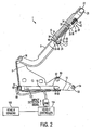
- Figure 1 shows an exemplary assembly 1 to pivotally connect a vehicle hood member 2 to a vehicle body 4 for lowering and raising movement about a horizontal pivot axis A--A between a closed position (as shown in Figure 1 ) and an open position (as shown in Figure 2 ).
- the assembly 1 includes a first hinge member 6 for mounting to the vehicle body 4, a second hinge member 8 for mounting to the vehicle hood member 2, and a vehicle hood mount 10 for connecting the vehicle hood member 2 to the second hinge member 8.
- a releasable lock 12 is provided for releasably locking the vehicle hood mount 10 to the second hinge member 8 in an operating position such that the second hinge member 8 and the vehicle hood mount 10 move together for the raising and lowering movements of the vehicle hood member 2 between the open and closed positions.
- a driving member 14 is movably connected to the first hinge member 6 on the vehicle body 4.
- An actuator 16 receives an impact detection signal and, in response to the impact detection signal, moves the driving member 14 to release the releasable lock 12 and move vehicle hood mount 10 from the operating position to an elevated position.
- the open and closed positions refer to the conventional movements of the hood member 2 about the axis A-A where the front end of the hood member 2 is raised to pivot the hood member 2 rearwardly and to permit access to the compartment beneath the hood member 2 (usually the engine compartment, although in rear-mounted engine vehicles the front compartment may be a storage compartment), and pivoted down and forwardly to close the compartment beneath the hood member 2.
- the operating position refers to the position of the hood mount 10 relative to the second hinge member 8, and specifically the position where they are fixed together so they move together as a unit to move the hood member 2 between the open and closed positions.
- the elevated position refers to the position of the hood mount 10 relative to the second hinge member 8, and the first hinge member 6 and vehicle body 4 as well, in which the hood mount 10 is raised up to elevate the rear/proximal end of the hood member 2.
- the elevated position is not the same as the normal open position (compare Figures 2 and 4 ). Instead, it is a slightly open/elevated condition at the rear/proximal end of the hood member 2 for creating space between the hood member 2 and body 4 to better handle a pedestrian impact, while the front/distal end may remain down and held by the latch that normally keeps it in the closed position.
- the elevated position raises the rear/proximal end, the movement has a forward and upward pivoting component, as opposed to the normal opening movement where the front/distal end is raised so that hood member 2 has a rearward and upward pivoting component.
- any references to pivoting action of the hood member 2 or components may include simple pivoting (i.e., pivot about an axis, compound movements that combine a simple pivot with other motions (e.g., pivoting and linear) or multiple pivots (e.g., multiple bar linkages), or other mechanisms that provide a general overall pivoting style of motion.
- Vehicle body mounting holes on the first hinge member 6 are used for mounting the first hinge member 6 to the vehicle body.
- Vehicle hood mounting holes on the vehicle hood mount 10 are used for mounting the vehicle hood mount 10 to the vehicle hood member 2.
- the vehicle hood mount 10 and the second hinge member 8 each have mounting holes that correspond to each other and that are used for mounting the vehicle hood mount 10 to the second hinge member 8.
- the assembly 1 hingedly connects the vehicle hood member 2 to the vehicle body 4 for permitting the pivoting of the vehicle hood member 2 about the horizontal axis A--A to access an inner space of the vehicle.
- the vehicle hood member 2 is a movable panel connected to the vehicle body 4.
- a pivot pin 18 is pivotally connected to the first hinge member 6 and/or the second hinge member 8 to provide pivotal movement of the vehicle hood member 2 about the horizontal pivot axis A--A between the closed position and the open position.
- the vehicle hood mount 10 is movably connected to the second hinge member 8 for movement relative to the second hinge member 8 between the operating position (as shown in Figures 1 and 2 ) and the elevated position (as shown in Figure 4 ).
- the vehicle hood mount 10 is releasably connected to the second hinge member 8 at a first end 20 thereof.
- the vehicle hood mount 10 is pivotally connected to the second hinge member 8 at a second end 22 thereof.
- a pivot pin 26 pivotally connects the vehicle hood mount 10 and the second hinge member 8 to one another at the second end 22.
- the pivot pin 26 is constructed and arranged to provide movement of vehicle hood mount 10 relative to the second hinge member 8 between the operating position and the elevated position.
- the second end 22 is positioned near a forward/distal end of the vehicle hood member 2 (or the vehicle) and the first end 20 is positioned rearward/proximal of the second end 22.
- the vehicle hood mount 10 and the second hinge member 8 move together for raising and lowering movements of the vehicle hood member 2 between the open and closed positions.
- the vehicle hood member 2 may be at the open position, at the closed position, or any other position between the open and closed positions.
- the vehicle hood mount 10 and the second hinge member 8 may be moved together for raising movement of the vehicle hood member 2 to the open position as shown in Figure 2 .
- the vehicle hood mount 10 and the second hinge member 8 may be moved together for lowering movement of the vehicle hood member 2 to the closed position as shown in Figure 1 .
- the releasable lock 12 is movable to a released position to permit the vehicle hood mount 10 to move relative to the second hinge member 8 between the operating and elevated positions.
- the releasable lock 12 may include the locking pin 24 and a sliding latch mechanism 28.
- the locking pin 24 is disposed on the second hinge member 8.
- the locking pin 24 projects laterally outwardly from the second hinge member 8 (toward the vehicle hood mount 10).
- the locking pin 24 has a raised portion at the free end (away from the second hinge member 8). It is appreciated, however that the locking pin member is but one example of different shapes, configurations and/or constructions of the locking structures that can be provided.
- the sliding latch mechanism 28 ensures that the vehicle hood mount 10 is connected to the second hinge member 8 when the vehicle hood mount 10 is in the operating position. That is, the sliding latch mechanism 28 ensures that the vehicle hood mount 10 and the second hinge member 8 move together as a single component under normal vehicle hood member opening/closing operations.
- the sliding latch mechanism 28 includes a latch member 30 and a bias member 32.
- the latch member 30 is slidably connected to the vehicle hood mount 10 by using pin members 34.
- both the latch member 30 and the vehicle hood mount 10 have pin member receiving slots 36, 38, respectively, for receiving the pin members 34 therein.
- the pin receiving slots 36 disposed on the latch member 30 have generally elongated configuration to provide a sliding movement of the latch member 30 with respect to the vehicle hood mount 10.
- the bias member 32 is a spring that is constructed and arranged to bias the latch member 30 of the releasable lock 12 toward the lock position.
- the latch member 30 includes a cam portion 40 disposed at a first end 42 thereof and a locking pin engaging portion 44 shaped as a recess disposed at a second end 46, opposite to the first end 42, thereof.
- the locking pin engaging portion 44 is constructed and arranged to be engaged with the locking pin 24 when the vehicle hood mount 10 is in its operating position. It is contemplated that the locking pin engaging portion may have any shape, configuration, and/or construction as long as it lockingly engages with the locking pin provided on the second hinge member. For example, instead of a C-shaped recess, a surface that just engages the bottom of the pin 24 may be used.
- the latch member 30 of the releasable lock 12 is linearly movable between the lock position and the release position. In one embodiment, the latch member 30 of the releasable lock 12 moves linearly to disengage the locking pin engaging portion 44 disposed on the latch member 30 from the locking pin 24.
- the linear, elongated shapes of slots 36, 38 guide this linear movement.
- the releasable lock described above is just one example of the types of arrangements that can be provided While the present application is described using pin and two lock engaging regions, it is, however, contemplated that any number (e.g., even only one pin and lock engaging region) of lock engaging structures can be provided to receive the locking structures for locking the vehicle hood mount to the second hinge member. Other arrangements, such as ratcheting arrangements or detent arrangements may also be provided. Other locking arrangements will be readily apparent to those skilled in the art, and the present application contemplates a broad range of possibilities for such locking mechanism.
- the vehicle hood mount 10 also may include a locking pin engaging portion 48.
- the locking pin engaging portion 48 of the vehicle hood mount 10 is engaged with the pin member 24 when the vehicle hood mount 10 is in its operating position. This optimal feature helps to limit movement of the hood mount 10 as it is moved back to the operating position.
- the vehicle hood mount 10 includes a cam surface 116 disposed on a bottom or lower end portion 118 thereof that ends with a downwardly protruding portion 120.
- the downwardly protruding portion 120 is disposed at a rearward/proximal end 122 of the bottom or lower end portion 118.
- the driving member 14 is pivotably connected to the first hinge member 6 (on the vehicle body 4) at a first end 50 thereof.
- a pivot or hinge pin 52 pivotally connects the driving member 14 and the first hinge member 6 to one another for providing a pivotal movement of the driving member 14 about the hinge or pivot pin 52.
- the driving member 14 includes a cam engaging member 54 positioned at a second end 56 thereof.
- the cam engaging member 54 is constructed and arranged to engage with the cam portion 40 of the latch member 30 so as to release the releasable lock 12 and to permit the vehicle hood mount 10 to move relative to the second hinge member 8 between the operating and elevated positions.
- the cam engaging member 54 may be in the form of a roller member.
- the driving member 14 is movably or pivotably connected to the actuator 16 at a third end 58 thereof.
- the actuator 16 is movably connected to the first hinge member 6 at its first end 64 and is connected to the driving member 14 at its second end 66. At its first end 64, a portion 68 of the actuator 16 is received in a groove 70 formed on the first hinge member 6 (on the vehicle body 4). The engagement between the actuator portion 68 and the groove 70 is constructed and arranged to permit a rotational movement of the actuator 16 about this end 64. In one embodiment, the groove 70 may be constructed and arranged to provide a limited rotational movement of the actuator 16 about its first end 64.
- the actuator 16 is horizontally mounted.
- the actuator 16 is a pyrotechnic actuator having a cylinder-piston arrangement.
- the piston is generally contained with the cylinder and is extended/moved by a detonation of a pyrotechnic or explosive charge. This ignition or detonation of the pyrotechnic or explosive charge causes the rapid expansion of gases in the cylinder, which results in extremely high pressure within the cylinder. This high pressured gases move the piston to a desired stroke.
- the assembly 1 of the present application allows a pyrotechnic charge to be mounted to the first hinge member 6 in a horizontal configuration.
- the actuator may have any other configuration, and/or construction as long as it, in response to the impact detection signal, is configured to move the driving member 14 to release the releasable lock 12 and move vehicle hood mount 10 from the operating position to the elevated position.
- the actuator may be mechanical, pneumatic, hydraulic, or electrical actuator that moves the driving member 14 from an initial position to a subsequent position in response to the received impact detection signal.
- Impact detection signal may be generated by a controller 104 of the vehicle.
- the vehicle controlled 104 may be configured to receive signals or data from one or more sensors 106 positioned at the front of the vehicle.
- These sensors 106 may include a pressure sensor that is configured to detect pressure produced by the impact with a pedestrian and/or a deformation sensor that is configured to detect deformation produced by the impact with a pedestrian.
- pressure sensors may use any type of pressure sensing technologies, for example, but not limited to, piezoresistive strain gauge, capacitive, electromagnetic, piezoelectric, optical, and potentiometric.
- Such pressure or deformation sensors may be placed on the engine or vehicle hood member and/or vehicle front bumper.
- the vehicle controller 104 may also receive signals or data from a velocity sensor, an acceleration sensor, and/or a vehicle brake system located in the vehicle and the controller may use these additional signals and/or data to generate the impact detection signal.
- a velocity sensor such as an acceleration sensor, and/or a vehicle brake system located in the vehicle
- the controller may use these additional signals and/or data to generate the impact detection signal.
- sensors are well-known and used for triggering other safety devices, such as air bags.
- pivot or hinge pin 18 pivotally connects the first hinge member and the second hinge members 6, 8 to one another for providing opening and closing movements of the vehicle hood member 2.
- the vehicle hood mount 10 When the opening and closing movements of the vehicle hood member 2 are provided, the vehicle hood mount 10 is in its operating position. In this operating position, the vehicle hood mount 10 is releasably locked to the second hinge member 8 by the releasable lock 12 so that both the vehicle hood mount 10 and the second hinge member 8 move together for raising and lowering movements of the vehicle hood member between the open and closed positions. Specifically, in this vehicle hood mount operating position, the locking pin 24 disposed on the second hinge member 8 is received by both the locking pin engaging portion 44 disposed on the latch member 30 and the locking pin engaging portion 48 disposed on the vehicle hood mount 10.
- the locking pin engaging portion 44 disposed on the latch member 30 remains engaged with the locking pin 24 under the force of the bias member 32 to lock the vehicle hood mount 10 to the second hinge member 8.
- the locking engagement of the locking pin engaging portion 44 disposed on the latch member 30 and the locking pin 24 causes the locking pin engaging portion 48 disposed on the vehicle hood mount 10 to also remain engaged with the locking pin 24.
- the actuator 16 and the driving member 14 remain in their respective initial configurations.
- the actuator 16 remains in a horizontal, initial configuration.
- the vehicle controller 104 receives data from various vehicle sensors 106, analyzes the received data and generates the impact detection signal when a pedestrian crash with the vehicle is detected. The vehicle controller 104 sends the impact detection signal to the actuator 16.
- At least a portion of the actuator 16 in response to the impact detection signal, is configured to move outwardly, thereby pushing the driving member 14, and causing the driving member 14 to pivot about its first end 50.
- a pyrotechnic (or explosive) charge stored in the cylinder 102 of the actuator 16 is ignited.
- This ignition or detonation of the pyrotechnic (or explosive) charge causes the rapid expansion of gases in the cylinder 102, which results in high pressure within the cylinder 102.
- These high pressured gases in the cylinder 102 move the piston 108 outwardly from the cylinder 102.
- one end 66 of the piston 108 is connected to the driving member 14, the outward movement of the piston 108 from the cylinder 102 moves or pushes the driving member 14.
- the pivotal movement of the driving member 14 about its first end 50 causes a roller member 54 disposed on the driving member 14 to release the releasable lock 12 to permit the vehicle hood mount 10 to move relative to the second hinge member 8 from the operating position.
- the vehicle hood member 2 may be pushed down and the releasable lock 12 may be re-engaged, allowing the vehicle to be driven without the vehicle hood member 2 remaining in the deployed position (e.g., in case of a false deployment).
- cam surface on the pin 24 engage cam surface on the locking pin engaging portion 44 disposed on the latch member 30.
- the camming action of these cam surfaces forces the latch member 30 outwardly in the direction of the arrow B, against the bias of the spring 32.
- the spring 32 is compressed. Once the pin 24 passes over the cam surface on the locking pin engaging portion 44, it snaps into locking engagement with the locking pin engaging portion 44.
- the spring 32 moves the latch member 30 inwardly (that is opposite to the direction of arrow B) to the lock position to lock the vehicle hood mount 10 (and the vehicle hood member 2) to the second hinge member 8.
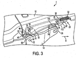
- Figure 5 illustrates an alternative embodiment in accordance with various aspects of the present patent application. This embodiment is similar to the embodiments previously described with respect to Figures 1-4 , except for the differences as will be noted below.
- the releasable lock 12 includes a shear pin 72 disposed on the second hinge member 8.
- the shear pin 72 is constructed and arranged to engage with shear pin engaging portion 74 disposed on the vehicle hood mount 10 to lock the vehicle hood mount 10 to the second hinge member 8 in the operating position.
- the shear pin engaging portion 74 may be in the form of an opening in which the shear pin 72 is received. This operating position of the vehicle hood mount 10 is illustrated in Figure 5 .
- At least a portion of the actuator 16 in response to the impact detection signal, is configured to move outwardly (in a horizontal direction), thereby pushing the driving member 14, and causing the driving member 14 to pivot about its first end 50.
- the pivotal movement of the driving member 14 about its first end 50 causes a roller member 54 disposed on the driving member 14 to release the releasable lock 12 to permit the vehicle hood mount 10 to move relative to the second hinge member 8 from the operating position.
- the driving member 14 pivots about the pivot pin 52
- surfaces 110 of the roller member 54 positioned at the third end 56 of the driving member 14 engages with the cam surfaces 116 of the vehicle hood mount 10 and rides along the cam surface 116.
- the continued operation of the pyrotechnic (or explosive) charge in the cylinder 102 causes further pivotal movement of the driving member 14 and causes the roller member 54 of the driving member 14 to apply upwardly force against the vehicle hood mount 10.
- This upwardly exerted force on the vehicle hood mount 10 causes the shear pin engaging portion 74 to break off the shear pin 72 so as to enable the movement of the vehicle hood mount 10 from the operating position to the elevated position.
- the shear pin engaging portion 74 is constructed and arranged to assist in shearing or breaking off the shear pin 72.
- the vehicle hood mount 10 is pivoted upwardly about the pivot pin 26 into its elevated position.
- the outwardly movement of the actuator 16 is converted to vertical, upwardly motion of the vehicle hood mount 10.
- the vehicle hood mount 10 is locked to the second hinge member 8 in the operating position by any other frangible fastening mechanisms, or other fastening mechanisms such as a threaded fastener, a bolt or a rivet that is constructed and arranged to shear or break off when stresses or forces are exerted thereon and thereby enable the movement of the vehicle hood mount 10 from the operating position to the elevated position.
- frangible fastening mechanisms such as a threaded fastener, a bolt or a rivet that is constructed and arranged to shear or break off when stresses or forces are exerted thereon and thereby enable the movement of the vehicle hood mount 10 from the operating position to the elevated position.
- the shear pin 72 and other alternative frangible fastening mechanisms discussed above are made from a plastic material or other frangible materials that are known to one skilled in the art.
- the pivot pin 26 pivotally connects the vehicle hood mount 10 and the second hinge member 8 to one another at the second end 22 of the vehicle hood mount 10 so as to provide movement of vehicle hood mount 10 relative to the second hinge member 8 between the operating position and the elevated position.
- a limiting pin 82 is positioned rearward/proximal of the second end 22 of the vehicle hood mount 10.
- the movement of the limiting pin 82 is limited or controlled by an opening or a slot 84 disposed on the vehicle hood mount 10.
- the opening or slot 84 has a generally elongated configuration so as to provide a linear, vertical movement of the limiting pin 82 therein.
- the vehicle hood mount 10 is pivoted upwardly about the pivot pin 26 into its elevated position.
- the upwardly movement of the vehicle hood mount 10 is controlled by the elongated opening 84 disposed on the vehicle hood mount 10.
- the linear, elongated shape of opening or slot 84 guide the movement of the limiting pin 82 therein. That is, this configuration (i.e., limiting pin 82 disposed in the elongated opening 84) of the hood mount 10 keeps the hood mount 10 and the vehicle hood member 2 connected to the vehicle hood mount 10 from popping-up too high.
- the vehicle hood mount 10 and the vehicle hood member 2 connected to the vehicle hood mount 10 are lifted to a desired height so as to provide a desired clearance between the vehicle hood member and its underlying components.
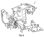
- Figure 6 illustrates an alternative embodiment in accordance with various aspects of the present patent application. This embodiment is similar to the embodiments previously described with respect to Figures 1-4 and Figure 5 , except for the differences as will be noted below.
- the vehicle hood mount 10 includes a cam surface 216 disposed near the first end 20 thereof.
- the driving member 14 is pivotably connected to the vehicle body 4 at the first end 50 thereof.
- the pivot or hinge pin 52 pivotally connects the driving member 14 and the hinge member to one another for providing a pivotal movement of the driving member 14 about the hinge or pivot pin 52.
- the driving member 14 includes the cam engaging member or roller member 54 positioned at the second end 56 thereof.
- the cam engaging member 54 is constructed and arranged to release the releasable lock 12 and to permit the vehicle hood mount 10 to move relative to the second hinge member 8 between the operating and elevated positions.
- the driving member 14 is movably or pivotably connected to the actuator 16 at the third end 58 thereof.
- the actuator 16 is movably connected to a vehicle member at its first end 64 and is connected to the driving member 14 at its second end 66.
- the releasable lock 12 of Figure 6 includes the shear pin 72 disposed on the second hinge member 8.
- the shear pin 72 is constructed and arranged to engage with shear pin engaging portion 74 disposed on the vehicle hood mount 10 to lock the vehicle hood mount 10 to the second hinge member 8 in the operating position.
- the shear pin engaging portion 74 may be in the form of an opening. This operating position of the vehicle hood mount 10 is illustrated in Figure 6 .
- the operation of the assembly 1 is shown and explained with respect to Figure 6 .
- the vehicle controller receives data from various vehicle sensors, analyzes the received data and generates the impact detection signal when a pedestrian crash with the vehicle is detected.
- the vehicle controller sends the impact detection signal to the actuator 16.
- At least a portion of the actuator 16 in response to the impact detection signal, is configured to move outwardly (in a horizontal direction), thereby pushing the driving member 14, and causing the driving member 14 to pivot about its first end 50.
- a pyrotechnic (or explosive) charge stored in the cylinder 102 of the actuator 16 is ignited.
- This ignition or detonation of the pyrotechnic (or explosive) charge causes the rapid expansion of gases in the cylinder 102, which results in high pressure within the cylinder 102.
- These high pressured gases in the cylinder 102 move the piston 108 outwardly from the cylinder 102.
- the outward movement (in a horizontal direction) of the piston 108 from the cylinder 102 moves or pushes the driving member 14.
- the continued operation of the pyrotechnic (or explosive) charge in the cylinder 102 causes a pivotal movement of the driving member 14 about the pivot pin 52.
- the pivotal movement of the driving member 14 about its first end 50 causes a roller member 54 disposed on the driving member 14 to release the releasable lock 12 to permit the vehicle hood mount 10 to move relative to the second hinge member 8 from the operating position.
- shear pin engaging portion 74 This upwardly exerted force on the portion 218 of the cam surface 216 of the vehicle hood mount 10 causes the shear pin engaging portion 74 to break off the shear pin 72 so as to enable the movement of the vehicle hood mount 10 from the operating position to the elevated position.
- the shear pin engaging portion 74 is constructed and arranged to assist in shearing or breaking off the shear pin 72.
- the vehicle hood mount 10 is pivoted upwardly about the pivot pin 26 into its elevated position.
- the outwardly movement of the actuator 16 is converted to vertical, upwardly motion of the vehicle hood mount 10.
- the illustrative embodiment of Figure 6 includes a configuration in which the limiting pin 82 disposed in the elongated opening 84 so as to control the upwardly movement of the vehicle hood mount 10 and to keep the vehicle hood mount 10 (and the vehicle hood member 2 connected to the vehicle hood mount 10) from popping-up too high.
- a support member 115 is disposed on the second hinge member 8.
- the support member 115 is constructed and arranged to support the vehicle hood mount 10 when it is in its operating position.
Landscapes
- Engineering & Computer Science (AREA)
- Mechanical Engineering (AREA)
- Superstructure Of Vehicle (AREA)
- Chemical & Material Sciences (AREA)
- Combustion & Propulsion (AREA)
- Transportation (AREA)
Description
- The present invention relates to a pedestrian protection vehicle hood hinge assembly.
- Vehicle hood hinges include one hinge member connected to a vehicle body and the other hinge member connected to a vehicle hood member. A pivot or hinge pin pivotally connects these two hinge members to one another for opening and closing movements of the vehicle hood member.
- In the event of a pedestrian crash (with the vehicle), the head of the pedestrian may be struck by a top surface of the vehicle hood member. This impact of the pedestrian's head against the hood may result in a serious brain injury of the pedestrian. Such a serious head injury may occur, for example, when there is an insufficient clearance between the Vehicle hood member and its rigid/stiff underlying components. Maintaining a sufficient gap between the vehicle hood member and its underlying components that allows for the pedestrian's head to have a controlled deceleration may often be difficult given the vehicle design constraints, such as aerodynamics and styling.
- Examples of known mechanisms for raising the vehicle hood are shown in
U.S. Patent Nos. 7,303,040 ;7,413.049 ;7,931,111 ;7,975,797 ; and8,069,943 . DocumentJP 2007245937A claim 1. - According to the present invention, there is provided an assembly to pivotally connect a vehicle hood member to a vehicle body for raising and lowering movement about a horizontal pivot axis between a closed position and an open position, the assembly comprising: a first hinge member for mounting to the vehicle body; a second hinge member for mounting to the vehicle hood member; a vehicle hood mount for connecting the vehicle hood member to the second hinge member, the vehicle hood mount being movably connected to the second hinge member for movement relative to the second hinge member between an operating position and an elevated position; a releasable lock for releasably locking the vehicle hood mount to the second hinge member in the operating position such that the second hinge member and the vehicle shood mount move together for the raising and lowering movements of the vehicle hood member between the open and closed positions, the releasable lock being movable to a released position to permit the vehicle hood mount to move relative to the second hinge member between the operating and elevated positions; a driving member movably connected to the first hinge member on the vehicle body; and an actuator for receiving an impact detection signal and, in response to the impact detection signal, configured to move the driving member so that said driving member releases the releasable lock and moves vehicle hood mount from the operating position to the elevated position.
- In an example, the vehicle hood mount is releasably connected to the second hinge member at a first end thereof and is pivotably connected to second hinge member at a second end thereof so as to provide the movement of the vehicle hood mount relative to the second hinge member between the operating position and the elevated position,
- In an example, the driving member is pivotably connected to the first hinge member at a first end thereof and is movably connected to the actuator at a second end thereof.
- In an example, the actuator is a pyrotechnic actuator.
- In an example, the releasable lock includes a latch member constructed and arranged to move from a lock position to a release position and a bias member constructed and arranged to bias the latch member toward the lock position.
- In an example, the releasable lock includes a locking pin disposed on the second hinge member, the locking pin being constructed and arranged to engage with locking pin engaging portion disposed on the latch member to lock the vehicle hood mount to the second hinge member.
- In an example, a pivotal movement of the driving member about its first end causes a roller member disposed on the driving member to engage with a portion of the latch member and move the latch member from the lock position to the release position.
- In an example, the releasable lock includes a shear pin disposed on the second hinge member, the shear pin being constructed and arranged to engage with shear pin engaging portion disposed on the vehicle hood mount to lock the vehicle hood mount to the second hinge member in the operating position.
- In an example, a pivotal movement of the driving member about its first end causes a portion of the vehicle hood mount to engage with and to break off a portion of the shear pin so as to enable the movement of the vehicle hood mount from the operating position to the elevated position.
- In an example, a pivotal movement of the driving member about its first end causes a roller member disposed on the driving member to engage with a portion of the vehicle hood mount and move the vehicle hood mount from the operating position to the elevated position.
- In an example, the shear pin is sheared off by the shear pin engaging portion during the movement of the vehicle hood mount from the operating position to the elevated position.
- In an example, the shear pin engaging portion is constructed and arranged to assist in shearing or breaking off the shear pin.
- In an example, the actuator is horizontally mounted.
- In an example, in response to the impact detection signal, at least a portion of the actuator is configured to move outwardly, thereby pushing the driving member, and, causing the driving member to pivot about its first end.
- In an example, a pivotal movement of the driving member about its first end causes a roller member disposed on the driving member to engage with and release the releasable lock so as to permit the vehicle hood mount move relative to the second hinge member from the operating position.
- In an example, continued operation of the actuator causes the driving member to pivot upwardly such that the roller member disposed thereon contacts the vehicle hood mount moving it to its elevated position, whereby the outwardly movement of the actuator is converted to vertical, upwardly motion of the vehicle hood mount.
- According to a second aspect of the present invention, there is provided a vehicle comprising a vehicle and a moveable vehicle hood member, and an assembly to pivotally connect the vehicle hood member to the vehicle hood body, wherein the assembly is an assembly according to the present invention.
- Any features mentioned above as being provided "in an example" may be provided in combination with any other such feature(s) in either the first or second aspect of the invention.
- In one embodiment of the present disclosure, an assembly to pivotally connect a vehicle hood member to a vehicle body for raising and lowering movement about a horizontal pivot axis between a closed position and an open position is provided. The assembly includes a first hinge member for mounting to the vehicle body; a second hinge member for mounting to the vehicle hood member; a vehicle hood mount for connecting the vehicle hood member to the second hinge member, the vehicle hood mount being movably connected to the second hinge member for movement relative to the second hinge member between an operating position and an elevated position; a releasable lock for releasably locking the vehicle hood mount to the second hinge member in the operating position such that the second hinge member and the vehicle hood mount move together for the raising and lowering movements of the vehicle hood member between the open and closed positions; a driving member movably connected to the first hinge member on the vehicle body; and an actuator for receiving an impact detection signal and, in response to the impact detection signal, configured to move the driving member so that said driving member releases the releasable lock and moves vehicle hood mount from the operating position to the elevated position. The releasable lock is movable to a released position to permit the vehicle hood mount to move relative to the second hinge member between the operating and elevated positions.
- Other objects, features, and advantages of one or more embodiments will become apparent from the following detailed description, and accompanying drawings, and the appended claims.
- Embodiments of the present invention will now be described in detail with reference to the accompanying drawings, in which;
- Various embodiments are disclosed, by way of example only, with reference to the accompanying schematic drawings in which corresponding reference symbols indicate corresponding parts, in which
-
Figure 1 shows a perspective view of an exemplary vehicle hood hinge assembly in accordance with an embodiment of the present disclosure; -
Figure 2 shows another view of the exemplary vehicle hood hinge assembly shown inFigure 1 , where a vehicle hood mount is in a normal operating position; -
Figure 3 shows an exploded view of a releasable lock and a driving member of the vehicle hood hinge assembly in accordance with an embodiment of the present disclosure; -
Figure 4 shows another view of the exemplary vehicle hood hinge assembly shown inFigure 1 , where the vehicle hood mount is in an elevated position; -
Figure 5 shows a perspective view of an exemplary vehicle hood hinge assembly in accordance with another embodiment of the present disclosure; and -
Figure 6 shows a perspective view of an exemplary vehicle hood hinge assembly in accordance with yet another embodiment of the present.disclosure.
-
-
Figure 1 shows anexemplary assembly 1 to pivotally connect a vehicle hood member 2 to a vehicle body 4 for lowering and raising movement about a horizontal pivot axis A--A between a closed position (as shown inFigure 1 ) and an open position (as shown inFigure 2 ). - The
assembly 1 includes afirst hinge member 6 for mounting to the vehicle body 4, asecond hinge member 8 for mounting to the vehicle hood member 2, and avehicle hood mount 10 for connecting the vehicle hood member 2 to thesecond hinge member 8. Areleasable lock 12 is provided for releasably locking thevehicle hood mount 10 to thesecond hinge member 8 in an operating position such that thesecond hinge member 8 and thevehicle hood mount 10 move together for the raising and lowering movements of the vehicle hood member 2 between the open and closed positions. Adriving member 14 is movably connected to thefirst hinge member 6 on the vehicle body 4. Anactuator 16 receives an impact detection signal and, in response to the impact detection signal, moves thedriving member 14 to release thereleasable lock 12 and movevehicle hood mount 10 from the operating position to an elevated position. - The open and closed positions refer to the conventional movements of the hood member 2 about the axis A-A where the front end of the hood member 2 is raised to pivot the hood member 2 rearwardly and to permit access to the compartment beneath the hood member 2 (usually the engine compartment, although in rear-mounted engine vehicles the front compartment may be a storage compartment), and pivoted down and forwardly to close the compartment beneath the hood member 2. The operating position refers to the position of the
hood mount 10 relative to thesecond hinge member 8, and specifically the position where they are fixed together so they move together as a unit to move the hood member 2 between the open and closed positions. The elevated position refers to the position of thehood mount 10 relative to thesecond hinge member 8, and thefirst hinge member 6 and vehicle body 4 as well, in which thehood mount 10 is raised up to elevate the rear/proximal end of the hood member 2. Thus, the elevated position is not the same as the normal open position (compareFigures 2 and4 ). Instead, it is a slightly open/elevated condition at the rear/proximal end of the hood member 2 for creating space between the hood member 2 and body 4 to better handle a pedestrian impact, while the front/distal end may remain down and held by the latch that normally keeps it in the closed position. Thus, because the elevated position raises the rear/proximal end, the movement has a forward and upward pivoting component, as opposed to the normal opening movement where the front/distal end is raised so that hood member 2 has a rearward and upward pivoting component. - As used herein, any references to pivoting action of the hood member 2 or components may include simple pivoting (i.e., pivot about an axis, compound movements that combine a simple pivot with other motions (e.g., pivoting and linear) or multiple pivots (e.g., multiple bar linkages), or other mechanisms that provide a general overall pivoting style of motion.
- Vehicle body mounting holes on the
first hinge member 6 are used for mounting thefirst hinge member 6 to the vehicle body. Vehicle hood mounting holes on thevehicle hood mount 10 are used for mounting thevehicle hood mount 10 to the vehicle hood member 2. Thevehicle hood mount 10 and thesecond hinge member 8 each have mounting holes that correspond to each other and that are used for mounting thevehicle hood mount 10 to thesecond hinge member 8. - The
assembly 1 hingedly connects the vehicle hood member 2 to the vehicle body 4 for permitting the pivoting of the vehicle hood member 2 about the horizontal axis A--A to access an inner space of the vehicle. The vehicle hood member 2 is a movable panel connected to the vehicle body 4. Apivot pin 18 is pivotally connected to thefirst hinge member 6 and/or thesecond hinge member 8 to provide pivotal movement of the vehicle hood member 2 about the horizontal pivot axis A--A between the closed position and the open position. - The
vehicle hood mount 10 is movably connected to thesecond hinge member 8 for movement relative to thesecond hinge member 8 between the operating position (as shown inFigures 1 and2 ) and the elevated position (as shown inFigure 4 ). - The
vehicle hood mount 10 is releasably connected to thesecond hinge member 8 at afirst end 20 thereof. Thevehicle hood mount 10 is pivotally connected to thesecond hinge member 8 at asecond end 22 thereof. Apivot pin 26 pivotally connects thevehicle hood mount 10 and thesecond hinge member 8 to one another at thesecond end 22. Thepivot pin 26 is constructed and arranged to provide movement ofvehicle hood mount 10 relative to thesecond hinge member 8 between the operating position and the elevated position. In one embodiment, thesecond end 22 is positioned near a forward/distal end of the vehicle hood member 2 (or the vehicle) and thefirst end 20 is positioned rearward/proximal of thesecond end 22. - When the vehicle hood mount 10 in the operating position, the
vehicle hood mount 10 and thesecond hinge member 8 move together for raising and lowering movements of the vehicle hood member 2 between the open and closed positions. When the vehicle hood mount 10 in the operating position, the vehicle hood member 2 may be at the open position, at the closed position, or any other position between the open and closed positions. For example, thevehicle hood mount 10 and thesecond hinge member 8 may be moved together for raising movement of the vehicle hood member 2 to the open position as shown inFigure 2 . Thevehicle hood mount 10 and thesecond hinge member 8 may be moved together for lowering movement of the vehicle hood member 2 to the closed position as shown inFigure 1 . - As will be clear from the discussion below, the
vehicle hood mount 10 is moved from the operating position (as shown inFigure 1 ) to the elevated position (as shown inFigure 4 ) first by disengaging the vehicle hood mount 10 from thesecond hinge member 8 at itsfirst end 20 and then rotating/pivoting the vehicle hood mount 10 about thepivot pin 26, positioned at itssecond end 22, to the elevated position. - The
releasable lock 12 is movable to a released position to permit the vehicle hood mount 10 to move relative to thesecond hinge member 8 between the operating and elevated positions. In one embodiment, thereleasable lock 12 may include the lockingpin 24 and a slidinglatch mechanism 28. - In the illustrated embodiment, as shown in
Figures 1-4 , the lockingpin 24 is disposed on thesecond hinge member 8. The lockingpin 24 projects laterally outwardly from the second hinge member 8 (toward the vehicle hood mount 10). In one embodiment, the lockingpin 24 has a raised portion at the free end (away from the second hinge member 8). It is appreciated, however that the locking pin member is but one example of different shapes, configurations and/or constructions of the locking structures that can be provided. - The sliding
latch mechanism 28 ensures that thevehicle hood mount 10 is connected to thesecond hinge member 8 when thevehicle hood mount 10 is in the operating position. That is, the slidinglatch mechanism 28 ensures that thevehicle hood mount 10 and thesecond hinge member 8 move together as a single component under normal vehicle hood member opening/closing operations. - The sliding
latch mechanism 28 includes alatch member 30 and abias member 32. Thelatch member 30 is slidably connected to the vehicle hood mount 10 by usingpin members 34. In one embodiment, both thelatch member 30 and thevehicle hood mount 10 have pinmember receiving slots pin members 34 therein. Thepin receiving slots 36 disposed on thelatch member 30 have generally elongated configuration to provide a sliding movement of thelatch member 30 with respect to thevehicle hood mount 10. In one embodiment, thebias member 32 is a spring that is constructed and arranged to bias thelatch member 30 of thereleasable lock 12 toward the lock position. - The
latch member 30 includes acam portion 40 disposed at afirst end 42 thereof and a lockingpin engaging portion 44 shaped as a recess disposed at asecond end 46, opposite to thefirst end 42, thereof. - The locking
pin engaging portion 44 is constructed and arranged to be engaged with the lockingpin 24 when thevehicle hood mount 10 is in its operating position. It is contemplated that the locking pin engaging portion may have any shape, configuration, and/or construction as long as it lockingly engages with the locking pin provided on the second hinge member. For example, instead of a C-shaped recess, a surface that just engages the bottom of thepin 24 may be used. - In one embodiment, the
latch member 30 of thereleasable lock 12 is linearly movable between the lock position and the release position. In one embodiment, thelatch member 30 of thereleasable lock 12 moves linearly to disengage the lockingpin engaging portion 44 disposed on thelatch member 30 from the lockingpin 24. The linear, elongated shapes ofslots - It should be appreciated that the releasable lock described above is just one example of the types of arrangements that can be provided While the present application is described using pin and two lock engaging regions, it is, however, contemplated that any number (e.g., even only one pin and lock engaging region) of lock engaging structures can be provided to receive the locking structures for locking the vehicle hood mount to the second hinge member. Other arrangements, such as ratcheting arrangements or detent arrangements may also be provided. Other locking arrangements will be readily apparent to those skilled in the art, and the present application contemplates a broad range of possibilities for such locking mechanism.
- The
vehicle hood mount 10 also may include a lockingpin engaging portion 48. The lockingpin engaging portion 48 of thevehicle hood mount 10 is engaged with thepin member 24 when thevehicle hood mount 10 is in its operating position. This optimal feature helps to limit movement of thehood mount 10 as it is moved back to the operating position. - The
vehicle hood mount 10 includes acam surface 116 disposed on a bottom orlower end portion 118 thereof that ends with a downwardly protrudingportion 120. The downwardly protrudingportion 120 is disposed at a rearward/proximal end 122 of the bottom orlower end portion 118. - The driving
member 14 is pivotably connected to the first hinge member 6 (on the vehicle body 4) at afirst end 50 thereof. A pivot orhinge pin 52 pivotally connects the drivingmember 14 and thefirst hinge member 6 to one another for providing a pivotal movement of the drivingmember 14 about the hinge orpivot pin 52. - The driving
member 14 includes acam engaging member 54 positioned at asecond end 56 thereof. As will be clear from the discussion below, thecam engaging member 54 is constructed and arranged to engage with thecam portion 40 of thelatch member 30 so as to release thereleasable lock 12 and to permit the vehicle hood mount 10 to move relative to thesecond hinge member 8 between the operating and elevated positions. In one embodiment, thecam engaging member 54 may be in the form of a roller member. The drivingmember 14 is movably or pivotably connected to theactuator 16 at athird end 58 thereof. - The
actuator 16 is movably connected to thefirst hinge member 6 at itsfirst end 64 and is connected to the drivingmember 14 at itssecond end 66. At itsfirst end 64, aportion 68 of theactuator 16 is received in agroove 70 formed on the first hinge member 6 (on the vehicle body 4). The engagement between theactuator portion 68 and thegroove 70 is constructed and arranged to permit a rotational movement of theactuator 16 about thisend 64. In one embodiment, thegroove 70 may be constructed and arranged to provide a limited rotational movement of theactuator 16 about itsfirst end 64. - In one embodiment, the
actuator 16 is horizontally mounted. In one embodiment, theactuator 16 is a pyrotechnic actuator having a cylinder-piston arrangement. The piston is generally contained with the cylinder and is extended/moved by a detonation of a pyrotechnic or explosive charge. This ignition or detonation of the pyrotechnic or explosive charge causes the rapid expansion of gases in the cylinder, which results in extremely high pressure within the cylinder. This high pressured gases move the piston to a desired stroke. Theassembly 1 of the present application allows a pyrotechnic charge to be mounted to thefirst hinge member 6 in a horizontal configuration. - It is contemplated that the actuator may have any other configuration, and/or construction as long as it, in response to the impact detection signal, is configured to move the driving
member 14 to release thereleasable lock 12 and move vehicle hood mount 10 from the operating position to the elevated position. For example, the actuator may be mechanical, pneumatic, hydraulic, or electrical actuator that moves the drivingmember 14 from an initial position to a subsequent position in response to the received impact detection signal. - Impact detection signal may be generated by a
controller 104 of the vehicle. The vehicle controlled 104 may be configured to receive signals or data from one ormore sensors 106 positioned at the front of the vehicle. Thesesensors 106 may include a pressure sensor that is configured to detect pressure produced by the impact with a pedestrian and/or a deformation sensor that is configured to detect deformation produced by the impact with a pedestrian. For example, such pressure sensors may use any type of pressure sensing technologies, for example, but not limited to, piezoresistive strain gauge, capacitive, electromagnetic, piezoelectric, optical, and potentiometric. Such pressure or deformation sensors may be placed on the engine or vehicle hood member and/or vehicle front bumper. Thevehicle controller 104 may also receive signals or data from a velocity sensor, an acceleration sensor, and/or a vehicle brake system located in the vehicle and the controller may use these additional signals and/or data to generate the impact detection signal. Such sensors are well-known and used for triggering other safety devices, such as air bags. - The operation of the
assembly 1 is shown and explained with respect toFigures 1-4 . - Under normal hinge operation, a pivotal movement of the vehicle hood member 2 about the horizontal pivot axis A-A between the closed position and the open position is provided. As noted above, the pivot or
hinge pin 18 pivotally connects the first hinge member and thesecond hinge members - When the opening and closing movements of the vehicle hood member 2 are provided, the
vehicle hood mount 10 is in its operating position. In this operating position, thevehicle hood mount 10 is releasably locked to thesecond hinge member 8 by thereleasable lock 12 so that both thevehicle hood mount 10 and thesecond hinge member 8 move together for raising and lowering movements of the vehicle hood member between the open and closed positions. Specifically, in this vehicle hood mount operating position, the lockingpin 24 disposed on thesecond hinge member 8 is received by both the lockingpin engaging portion 44 disposed on thelatch member 30 and the lockingpin engaging portion 48 disposed on thevehicle hood mount 10. The lockingpin engaging portion 44 disposed on thelatch member 30 remains engaged with the lockingpin 24 under the force of thebias member 32 to lock the vehicle hood mount 10 to thesecond hinge member 8. The locking engagement of the lockingpin engaging portion 44 disposed on thelatch member 30 and the lockingpin 24 causes the lockingpin engaging portion 48 disposed on the vehicle hood mount 10 to also remain engaged with the lockingpin 24. - When the
vehicle hood mount 10 is in its operating position and the vehicle hood member 2 is moved between its open and closed positions, theactuator 16 and the drivingmember 14 remain in their respective initial configurations. For example, theactuator 16 remains in a horizontal, initial configuration. - The
vehicle controller 104 receives data fromvarious vehicle sensors 106, analyzes the received data and generates the impact detection signal when a pedestrian crash with the vehicle is detected. Thevehicle controller 104 sends the impact detection signal to theactuator 16. - In one embodiment, in response to the impact detection signal, at least a portion of the
actuator 16 is configured to move outwardly, thereby pushing the drivingmember 14, and causing the drivingmember 14 to pivot about itsfirst end 50. - Specifically, in response to the impact detection signal, a pyrotechnic (or explosive) charge stored in the
cylinder 102 of theactuator 16 is ignited. This ignition or detonation of the pyrotechnic (or explosive) charge causes the rapid expansion of gases in thecylinder 102, which results in high pressure within thecylinder 102. These high pressured gases in thecylinder 102 move thepiston 108 outwardly from thecylinder 102. As oneend 66 of thepiston 108 is connected to the drivingmember 14, the outward movement of thepiston 108 from thecylinder 102 moves or pushes the drivingmember 14. - The continued operation of the pyrotechnic (or explosive) charge in the
cylinder 102 also causes theactuator portion 68 to pivot or rotate in thegroove 70 at itsfirst end 64. The rotational movement of theactuator 16 about itsfirst end 64 and the outwardly movement of thepiston 108 from thecylinder 102 together provide a pivotal movement of the driving member about thepivot pin 52. - The pivotal movement of the driving
member 14 about itsfirst end 50 causes aroller member 54 disposed on the drivingmember 14 to release thereleasable lock 12 to permit the vehicle hood mount 10 to move relative to thesecond hinge member 8 from the operating position. - Specifically, as the driving
member 14 pivots about thepivot pin 52,surfaces 110 of theroller member 54 positioned at thethird end 56 of the drivingmember 14 engagessurfaces 112 of thecam member 40 disposed on thelatch member 30. The camming action of the cam surfaces 110 and 112 initially forces thelatch member 30 to move outwardly (forwardly in the direction of an arrow B) against the bias of thebias member 32 relative to thesecond hinge member 8 and thehood mount 10. Aslatch member 30 is linearly moved outwardly in the direction of the arrow B, thebias member 32 of thereleasable lock 12 is compressed. Also, aslatch member 30 is linearly moved outwardly in the direction of the arrow B, the lockingpin engaging portion 44 disposed on thelatch member 30 disengages from the lockingpin 24. Once the lockingpin engaging portion 44 is disengaged from the lockingpin 24, continued pivotal movement of the drivingmember 14 by the actuator 16 contacts theroller member 54 against thecam surface 116 of thehood mount 10 to pivot it forwardly and upwardly about thepivot pin 26 into its elevated position. Thus, the outwardly movement of theactuator 16 is converted to vertical, upwardly motion of thevehicle hood mount 10. - The forwardly and upwardly movement of the
vehicle hood mount 10 is controlled by the downwardly slopingcamming surface 116 and the downwardly protrudingportion 120 of thehood mount 10. That is, this configuration (i.e., the downwardly slopingcamming surface 116 and the downwardly protruding portion 120) of thehood mount 10 keeps thehood mount 10 and the vehicle hood member 2 connected to the vehicle hood mount 10 from popping-up too high. In one embodiment, when the pyrotechnic charge in theactuator 16 is at the end of its stroke, thevehicle hood mount 10 and the vehicle hood member 2 connected to thevehicle hood mount 10 are lifted to a desired height so as to provide a desired clearance between the vehicle hood member and its underlying components. - Once deployed, the vehicle hood member 2 may be pushed down and the
releasable lock 12 may be re-engaged, allowing the vehicle to be driven without the vehicle hood member 2 remaining in the deployed position (e.g., in case of a false deployment). - Specifically, when the vehicle hood member 2 and the vehicle hood mount 10 attached to the vehicle hood member 2 may be pushed downwardly, cam surface on the
pin 24 engage cam surface on the lockingpin engaging portion 44 disposed on thelatch member 30. The camming action of these cam surfaces forces thelatch member 30 outwardly in the direction of the arrow B, against the bias of thespring 32. As thelatch member 30 is linearly moved outwardly, thespring 32 is compressed. Once thepin 24 passes over the cam surface on the lockingpin engaging portion 44, it snaps into locking engagement with the lockingpin engaging portion 44. Thespring 32 moves thelatch member 30 inwardly (that is opposite to the direction of arrow B) to the lock position to lock the vehicle hood mount 10 (and the vehicle hood member 2) to thesecond hinge member 8. - In one embodiment, when deployed, the main hinge pivot axis remains at the same height, allowing it to be located underneath areas of the vehicle other than the hood (i.e., partially covered by the A pillar).
-
Figure 5 illustrates an alternative embodiment in accordance with various aspects of the present patent application. This embodiment is similar to the embodiments previously described with respect toFigures 1-4 , except for the differences as will be noted below. - In the illustrated embodiment of
Figure 5 , thereleasable lock 12 includes ashear pin 72 disposed on thesecond hinge member 8. Theshear pin 72 is constructed and arranged to engage with shearpin engaging portion 74 disposed on the vehicle hood mount 10 to lock the vehicle hood mount 10 to thesecond hinge member 8 in the operating position. In the illustrated embodiment, the shearpin engaging portion 74 may be in the form of an opening in which theshear pin 72 is received. This operating position of thevehicle hood mount 10 is illustrated inFigure 5 . - The operation of the assembly shown in
Figure 5 is similar to the operation of theassembly 1 in the previously described embodiments (Figures 1-4 ), except for the differences as will be noted below. - In one embodiment, in response to the impact detection signal, at least a portion of the
actuator 16 is configured to move outwardly (in a horizontal direction), thereby pushing the drivingmember 14, and causing the drivingmember 14 to pivot about itsfirst end 50. - The pivotal movement of the driving
member 14 about itsfirst end 50 causes aroller member 54 disposed on the drivingmember 14 to release thereleasable lock 12 to permit the vehicle hood mount 10 to move relative to thesecond hinge member 8 from the operating position. - Specifically, as the driving
member 14 pivots about thepivot pin 52,surfaces 110 of theroller member 54 positioned at thethird end 56 of the drivingmember 14 engages with the cam surfaces 116 of thevehicle hood mount 10 and rides along thecam surface 116. The continued operation of the pyrotechnic (or explosive) charge in thecylinder 102 causes further pivotal movement of the drivingmember 14 and causes theroller member 54 of the drivingmember 14 to apply upwardly force against thevehicle hood mount 10. This upwardly exerted force on the vehicle hood mount 10 causes the shearpin engaging portion 74 to break off theshear pin 72 so as to enable the movement of the vehicle hood mount 10 from the operating position to the elevated position. In one embodiment, the shearpin engaging portion 74 is constructed and arranged to assist in shearing or breaking off theshear pin 72. - Once the
shear pin 72 is sheared or broken by the shearpin engaging portion 74, thevehicle hood mount 10 is pivoted upwardly about thepivot pin 26 into its elevated position. Thus, the outwardly movement of theactuator 16 is converted to vertical, upwardly motion of thevehicle hood mount 10. - In other embodiments, the
vehicle hood mount 10 is locked to thesecond hinge member 8 in the operating position by any other frangible fastening mechanisms, or other fastening mechanisms such as a threaded fastener, a bolt or a rivet that is constructed and arranged to shear or break off when stresses or forces are exerted thereon and thereby enable the movement of the vehicle hood mount 10 from the operating position to the elevated position. In one embodiment, theshear pin 72 and other alternative frangible fastening mechanisms discussed above are made from a plastic material or other frangible materials that are known to one skilled in the art. - As noted in the embodiments previously described with respect to
Figures 1-4 , thepivot pin 26 pivotally connects thevehicle hood mount 10 and thesecond hinge member 8 to one another at thesecond end 22 of the vehicle hood mount 10 so as to provide movement of vehicle hood mount 10 relative to thesecond hinge member 8 between the operating position and the elevated position. In the illustrated embodiment ofFigure 5 , in addition to thepivot pin 26, a limitingpin 82 is positioned rearward/proximal of thesecond end 22 of thevehicle hood mount 10. - The movement of the limiting
pin 82 is limited or controlled by an opening or aslot 84 disposed on thevehicle hood mount 10. The opening orslot 84 has a generally elongated configuration so as to provide a linear, vertical movement of the limitingpin 82 therein. - Once the
shear pin 72 is sheared or broken off, thevehicle hood mount 10 is pivoted upwardly about thepivot pin 26 into its elevated position. The upwardly movement of thevehicle hood mount 10 is controlled by theelongated opening 84 disposed on thevehicle hood mount 10. The linear, elongated shape of opening orslot 84 guide the movement of the limitingpin 82 therein. That is, this configuration (i.e., limitingpin 82 disposed in the elongated opening 84) of thehood mount 10 keeps thehood mount 10 and the vehicle hood member 2 connected to the vehicle hood mount 10 from popping-up too high. In one embodiment, when the pyrotechnic charge in theactuator 16 is at the end of its stroke, thevehicle hood mount 10 and the vehicle hood member 2 connected to thevehicle hood mount 10 are lifted to a desired height so as to provide a desired clearance between the vehicle hood member and its underlying components. -
Figure 6 illustrates an alternative embodiment in accordance with various aspects of the present patent application. This embodiment is similar to the embodiments previously described with respect toFigures 1-4 andFigure 5 , except for the differences as will be noted below. - The
vehicle hood mount 10 includes acam surface 216 disposed near thefirst end 20 thereof. The drivingmember 14 is pivotably connected to the vehicle body 4 at thefirst end 50 thereof. The pivot orhinge pin 52 pivotally connects the drivingmember 14 and the hinge member to one another for providing a pivotal movement of the drivingmember 14 about the hinge orpivot pin 52. - The driving
member 14 includes the cam engaging member orroller member 54 positioned at thesecond end 56 thereof. As will be clear from the discussion below, thecam engaging member 54 is constructed and arranged to release thereleasable lock 12 and to permit the vehicle hood mount 10 to move relative to thesecond hinge member 8 between the operating and elevated positions. The drivingmember 14 is movably or pivotably connected to theactuator 16 at thethird end 58 thereof. Theactuator 16 is movably connected to a vehicle member at itsfirst end 64 and is connected to the drivingmember 14 at itssecond end 66. - Similar to the embodiment previously described with respect to
Figure 5 , thereleasable lock 12 ofFigure 6 includes theshear pin 72 disposed on thesecond hinge member 8. Theshear pin 72 is constructed and arranged to engage with shearpin engaging portion 74 disposed on the vehicle hood mount 10 to lock the vehicle hood mount 10 to thesecond hinge member 8 in the operating position. In the illustrated embodiment, the shearpin engaging portion 74 may be in the form of an opening. This operating position of thevehicle hood mount 10 is illustrated inFigure 6 . - The operation of the
assembly 1 is shown and explained with respect toFigure 6 . The vehicle controller receives data from various vehicle sensors, analyzes the received data and generates the impact detection signal when a pedestrian crash with the vehicle is detected. The vehicle controller sends the impact detection signal to theactuator 16. - In one embodiment, in response to the impact detection signal, at least a portion of the
actuator 16 is configured to move outwardly (in a horizontal direction), thereby pushing the drivingmember 14, and causing the drivingmember 14 to pivot about itsfirst end 50. - Specifically, in response to the impact detection signal, a pyrotechnic (or explosive) charge stored in the
cylinder 102 of theactuator 16 is ignited. This ignition or detonation of the pyrotechnic (or explosive) charge causes the rapid expansion of gases in thecylinder 102, which results in high pressure within thecylinder 102. These high pressured gases in thecylinder 102 move thepiston 108 outwardly from thecylinder 102. As oneend 66 of thepiston 108 is connected to the drivingmember 14, the outward movement (in a horizontal direction) of thepiston 108 from thecylinder 102 moves or pushes the drivingmember 14. The continued operation of the pyrotechnic (or explosive) charge in thecylinder 102 causes a pivotal movement of the drivingmember 14 about thepivot pin 52. - The pivotal movement of the driving
member 14 about itsfirst end 50 causes aroller member 54 disposed on the drivingmember 14 to release thereleasable lock 12 to permit the vehicle hood mount 10 to move relative to thesecond hinge member 8 from the operating position. - Specifically, as the driving
member 14 pivots about thepivot pin 52,surfaces 210 of theroller member 54 positioned at thethird end 56 of the driving member 14engages with thecam surface 216 of thehood mount 10 and rides along thecam surface 216 until thesurfaces 210 of theroller member 54 are in engagement withportion 218 of thecam surface 216 of thevehicle hood mount 10. The continued operation of the pyrotechnic (or explosive) charge in thecylinder 102 causes further pivotal movement of the drivingmember 14 and causes theroller member 54 of the drivingmember 14 to apply upwardly force against theportion 218 of thecam surface 216 of thevehicle hood mount 10. This upwardly exerted force on theportion 218 of thecam surface 216 of the vehicle hood mount 10 causes the shearpin engaging portion 74 to break off theshear pin 72 so as to enable the movement of the vehicle hood mount 10 from the operating position to the elevated position. In one embodiment, the shearpin engaging portion 74 is constructed and arranged to assist in shearing or breaking off theshear pin 72. - Once the
shear pin 72 is sheared or broken by the shearpin engaging portion 74, thevehicle hood mount 10 is pivoted upwardly about thepivot pin 26 into its elevated position. Thus, the outwardly movement of theactuator 16 is converted to vertical, upwardly motion of thevehicle hood mount 10. - Similar to the embodiment previously described with respect to
Figure 5 , the illustrative embodiment ofFigure 6 includes a configuration in which the limitingpin 82 disposed in theelongated opening 84 so as to control the upwardly movement of thevehicle hood mount 10 and to keep the vehicle hood mount 10 (and the vehicle hood member 2 connected to the vehicle hood mount 10) from popping-up too high. - Also, in the illustrative embodiment of
Figure 6 , asupport member 115 is disposed on thesecond hinge member 8. Thesupport member 115 is constructed and arranged to support thevehicle hood mount 10 when it is in its operating position.
Claims (16)
- An assembly to pivotally connect a vehicle hood member to a vehicle body for raising and lowering movement about a horizontal pivot axis between a closed position and an open position, the assembly comprising:a first hinge member (6) for mounting to the vehicle body;a second hinge member (8) for mounting to the vehicle hood member;a vehicle hood mount (10) for connecting the vehicle hood member to the second hinge member, the vehicle hood mount being movably connected to the second hinge member for movement relative to the second hinge member between an operating position and an elevated position;a releasable lock (12) for releasably locking the vehicle hood mount to the second hinge member in the operating position such that the second hinge member and the vehicle hood mount move together for the raising and lowering movements of the vehicle hood member between the open and closed positions, the releasable lock being movable to a released position to permit the vehicle hood mount to move relative to the second hinge member between the operating and elevated positions;characterized by a driving member (14) movably connected to the first hinge member on the vehicle body; andan actuator (16) for receiving an impact detection signal and, in response to the impact detection signal, configured to move the driving member so that said driving member releases the releasable lock and moves the vehicle hood mount from the operating position to the elevated position.
- The assembly of claim 1, wherein the vehicle hood (10) mount is releasably connected to the second hinge member (8) at a first end (20) thereof and is pivotably connected to second hinge member at a second end (22) thereof so as to provide the movement of the vehicle hood mount relative to the second hinge member between the operating position and the elevated position.
- The assembly of claim 1 or 2, wherein the driving member (14) is pivotably connected to the first hinge member (6) at a first end (67) thereof and is movably connected to the actuator (16) at a second end (66) thereof.
- The assembly of any of claims 1 to 3, wherein the actuator (16) is a pyrotechnic actuator.
- The assembly of any of claims 1 to 4, wherein the releasable lock (12) includes a latch member (30) constructed arranged to move from a lock position to a release position and a bias member (32) constructed and arranged to bias the latch member toward the lock position.
- The assembly of claim 5, wherein the releasable lock includes a locking pin (24) disposed on the second hinge member, (8) the locking pin being constructed and arranged to engage with locking pin engaging portion (44) disposed on the latch member (30) to lock the vehicle hood mount to the second hinge member (8).
- The assembly of claim 5 or 6, wherein a pivotal movement of the driving member (14) about its first end (50) causes a roller member (54) disposed on the driving member to engage with a portion of the latch member (30) and move the latch member (30) from the lock position to the release position.
- The assembly of any of claims 1 to 7, wherein the releasable lock includes a shear pin (72) disposed on the second hinge member (8) the shear pin being constructed and arranged to engage with shear pin engaging portion (74) disposed on the vehicle hood mount (20) to lock the vehicle hood mount to the second hinge member (8) in the operating position.
- The assembly of claim 8, wherein a pivotal movement of the driving membe (14). about its first end (50) causes a portion, of the vehicle hood mount to engage with and to break off a portion of the shear pin (72) so as to enable the movement of the vehicle hood mount (10) from the operating position to the elevated position.
- The assembly of any of claims 1 to 9, wherein a pivotal movement of the driving member (14) about its first end (50) causes a roller member (54) disposed on the driving member (14) to engage with a portion of the vehicle hood mount (10) and move the vehicle hood moun (10) from the operating position to the elevated position.
- The assembly of any of claims 8 to 10, wherein the shear pin (72) is sheared off by the shear pin engaging portion (74) during the movement of the vehicle hood mount (10) from the operating position to the elevated position.
- The assembly of any of claims 8 to 11, wherein the shear pin engaging portion (74) is constructed and arranged to assist in shearing or breaking off the shear pin.
- The assembly of any of claims 1 to 12, wherein the actuator (16) is horizontally mounted.
- The assembly of claim 13, wherein, in response to the impact detection signal, at least a portion of the actuator (16) is configured to move outwardly, thereby pushing the driving member (14), and causing the driving member to pivot about its first end.
- The assembly of claim 14, wherein a pivotal movement of the driving member (14) about its first end causes a roller member (54) disposed on the driving member (14) engage with and release the releasable lock (12) so as to permit the vehicle hood mount (10) move relative to the second hinge member 3 from the operating position.
- The assemby of claim 15, wherein continued operation of the actuator causes the driving member (14) to pivot upwardly such that the roller member (54) disposed thereon contacts the vehicle hood mount (10) moving it to its elevated position, whereby the outwardly movement of the actuator is converted to vertical, upwardly motion of the vehicle hood mount (20).
Applications Claiming Priority (1)
| Application Number | Priority Date | Filing Date | Title |
|---|---|---|---|
| US13/774,680 US8768574B1 (en) | 2013-02-22 | 2013-02-22 | Pedestrian protection vehicle hood hinge assembly |
Publications (2)
| Publication Number | Publication Date |
|---|---|
| EP2769887A1 EP2769887A1 (en) | 2014-08-27 |
| EP2769887B1 true EP2769887B1 (en) | 2016-08-17 |
Family
ID=50272269
Family Applications (1)
| Application Number | Title | Priority Date | Filing Date |
|---|---|---|---|
| EP14156024.3A Active EP2769887B1 (en) | 2013-02-22 | 2014-02-20 | An assembly for pedestrian protection |
Country Status (3)
| Country | Link |
|---|---|
| US (1) | US8768574B1 (en) |
| EP (1) | EP2769887B1 (en) |
| ES (1) | ES2593801T3 (en) |
Cited By (1)
| Publication number | Priority date | Publication date | Assignee | Title |
|---|---|---|---|---|
| US12296783B2 (en) | 2022-05-03 | 2025-05-13 | Magna Closures Inc. | Actuation system for a closure panel including a pop up safety system for hinges |
Families Citing this family (16)
| Publication number | Priority date | Publication date | Assignee | Title |
|---|---|---|---|---|
| DE102014212223B4 (en) * | 2014-06-25 | 2016-03-31 | Bayerische Motoren Werke Aktiengesellschaft | Hinge for pivotally attaching a body component |
| EP3178708B1 (en) * | 2014-08-07 | 2019-05-22 | Toyota Jidosha Kabushiki Kaisha | Pop-up hood device for vehicle |
| KR101637747B1 (en) * | 2014-11-26 | 2016-07-07 | 현대자동차주식회사 | Breaking type hood hinge device |
| DE102015010395B3 (en) * | 2015-08-10 | 2016-11-17 | Audi Ag | Front door hinge and associated motor vehicle |
| JP6245235B2 (en) * | 2015-08-21 | 2017-12-13 | トヨタ自動車株式会社 | Pop-up hood device for vehicle |
| DE102016113684B4 (en) * | 2016-07-25 | 2024-05-23 | Dr. Ing. H.C. F. Porsche Aktiengesellschaft | Hinge device with an integrated pedestrian protection for a front hood |
| US10315612B2 (en) * | 2016-08-24 | 2019-06-11 | Honda Motor Co., Ltd. | Vehicle hood lift system |
| US11383672B2 (en) * | 2018-11-27 | 2022-07-12 | Magna Closures Inc. | Active pedestrian hood hinge with integrated latch assembly |
| JP7064457B2 (en) * | 2019-02-19 | 2022-05-10 | 本田技研工業株式会社 | Vehicle pop-up hood device |
| DE102019108935B4 (en) * | 2019-04-05 | 2024-03-07 | Dr. Ing. H.C. F. Porsche Aktiengesellschaft | Hinge device for a front hood of a motor vehicle |
| DE102020108386A1 (en) | 2020-03-26 | 2021-09-30 | Bayerische Motoren Werke Aktiengesellschaft | Hinge device for a front flap of a motor vehicle and a protection system for protecting a person outside a motor vehicle |
| US11560118B2 (en) * | 2020-06-25 | 2023-01-24 | Edscha Enginerring Gmbh | Drive assembly for driving a vehicle flap |
| DE102020118955A1 (en) | 2020-07-17 | 2022-01-20 | Bayerische Motoren Werke Aktiengesellschaft | HINGE FOR ADJUSTING A FRONT HOOD FROM A NORMAL POSITION TO A PROTECTIVE POSITION |
| EP4177117A1 (en) * | 2021-11-03 | 2023-05-10 | Innomotive Systems Hainichen GmbH | Bonnet hinge for a vehicle |
| DE102022116438A1 (en) * | 2022-07-01 | 2024-01-04 | Bayerische Motoren Werke Aktiengesellschaft | Front lid hinge for a motor vehicle and motor vehicle with such a front lid hinge |
| US12077126B2 (en) * | 2022-07-05 | 2024-09-03 | Hyundai Motor Company | Active hood system |
Family Cites Families (50)
| Publication number | Priority date | Publication date | Assignee | Title |
|---|---|---|---|---|
| US2000172A (en) | 1933-10-23 | 1935-05-07 | American Seating Co | Hinge |
| US5687453A (en) | 1995-04-17 | 1997-11-18 | Chrysler Corporation | Grounding washer and arrangements for conductive hinge joints |
| DE19514388C2 (en) | 1995-04-19 | 2002-04-18 | Scharwaechter Gmbh Co Kg | Door or flap hinge for motor vehicles |
| DE19922107C1 (en) | 1999-05-17 | 2001-01-18 | Edscha Ag | Front hood assembly for motor vehicle has multijoint hinge with connecting rod which pivot front hood to chassis, such that connecting rod varies in length under collision impact |
| JP2002544058A (en) | 1999-05-17 | 2002-12-24 | エドシャ・アクチェンゲゼルシャフト | Front bonnet structure |
| AU5961800A (en) | 1999-05-17 | 2000-12-05 | Edscha Ag | Front hood system |
| JP3312692B2 (en) | 1999-07-09 | 2002-08-12 | 本田技研工業株式会社 | Vehicle hood device |
| JP3377763B2 (en) | 1999-07-08 | 2003-02-17 | 本田技研工業株式会社 | Vehicle hood device |
| JP3320681B2 (en) | 1999-07-19 | 2002-09-03 | 本田技研工業株式会社 | Vehicle hood device |
| EP1078826B1 (en) | 1999-08-21 | 2002-01-02 | Ford Global Technologies, Inc., A subsidiary of Ford Motor Company | Pedestrian safety module device |
| US6554093B2 (en) | 2000-07-19 | 2003-04-29 | Honda Giken Kogyo Kabushiki Kaisha | Vehicular hood device |
| JP4140953B2 (en) | 2001-03-13 | 2008-08-27 | オートリブ デベロップメント アクテボラゲット | Vehicle safety mechanism |
| DE10136897A1 (en) | 2001-07-28 | 2003-02-06 | Opel Adam Ag | Double arm bonnet (hood) hinge has at least one arm consisting of two struts pivoted to each other |
| EP1302388B1 (en) | 2001-10-16 | 2006-01-18 | Ford Global Technologies, LLC | Vehicle hood assembly for pedestrian protection |
| GB0207146D0 (en) | 2002-03-27 | 2002-05-08 | Ford Global Tech Inc | A hinge assembly and a motor vehicle including same |
| US6712169B2 (en) | 2002-05-16 | 2004-03-30 | Delphi Technologies, Inc. | Displaceable automotive hood assembly |
| DE10252285A1 (en) | 2002-11-06 | 2004-05-27 | Takata-Petri Ag | Hinge for connecting a hood, especially an engine hood, to a vehicle body is designed so that it releases the hood in the event of a collision, especially with a pedestrian |
| JP4453285B2 (en) | 2003-07-09 | 2010-04-21 | トヨタ自動車株式会社 | Control device for collision protection device |
| JP4612790B2 (en) | 2003-08-01 | 2011-01-12 | キヤノン株式会社 | Zoom lens and imaging apparatus having the same |
| JP4108020B2 (en) | 2003-08-19 | 2008-06-25 | ダイハツ工業株式会社 | Vehicle hood structure |
| JP4206895B2 (en) | 2003-10-15 | 2009-01-14 | 三菱自動車工業株式会社 | Vehicle hood device |
| US7089626B2 (en) | 2004-02-12 | 2006-08-15 | Ford Motor Company | Adjustable door hinge |
| GB2410924B (en) | 2004-02-14 | 2007-04-11 | Ford Global Tech Llc | A hinge arrangement |
| SE526817C2 (en) | 2004-03-05 | 2005-11-08 | Saab Automobile | Hoist |
| US7303040B2 (en) | 2004-05-18 | 2007-12-04 | Autolive Asp, Inc. | Active vehicle hood system and method |
| US7594555B2 (en) | 2004-11-17 | 2009-09-29 | Delphi Technologies, Inc. | Hood lift mechanism and method |
| US7232178B2 (en) | 2005-02-10 | 2007-06-19 | General Motors Corporation | Vehicle hood assembly and method of elevating vehicle hood |
| EP1736380B1 (en) | 2005-06-23 | 2008-07-09 | Mazda Motor Corporation | A safety device of a vehicle and a vehicle provided therewith |
| EP1759937B1 (en) | 2005-08-30 | 2010-05-26 | Mazda Motor Corporation | Vehicle hood structure |
| US20070062747A1 (en) | 2005-09-20 | 2007-03-22 | Erwin Gregory S | Hood hinge assembly for vehicle |
| KR100770135B1 (en) * | 2005-11-08 | 2007-10-24 | 현대모비스 주식회사 | Pedestrian Protective Device for Car Hood |
| GB0602586D0 (en) | 2006-02-10 | 2006-03-22 | Ford Global Tech Llc | A hinge mechanism |
| JP4884042B2 (en) * | 2006-03-16 | 2012-02-22 | 日本発條株式会社 | Automobile having a hood lifting structure |
| EP1842745B1 (en) | 2006-04-04 | 2011-08-17 | Ford Global Technologies, LLC | A bonnet bumpstop for a vehicle |
| EP1842746B1 (en) | 2006-04-04 | 2011-10-26 | Volvo Car Corporation | A bonnet for a vehicle |
| US7597166B2 (en) | 2006-04-20 | 2009-10-06 | Autoliv Asp, Inc. | Hinge device for pedestrian protection system |
| US7546663B2 (en) | 2006-10-13 | 2009-06-16 | M & C Corporation | Hood hinge with coil spring |
| US7413049B2 (en) | 2006-10-18 | 2008-08-19 | Antolin Asp, Inc. | Pedestrian protection hood lifting systems |
| JP4297161B2 (en) | 2006-12-28 | 2009-07-15 | トヨタ自動車株式会社 | Pop-up hood device for vehicle |
| JP4291850B2 (en) | 2006-12-28 | 2009-07-08 | トヨタ自動車株式会社 | Pop-up hood device for vehicle |
| DE602008003413D1 (en) | 2007-03-07 | 2010-12-23 | Alcoa Inc | MSTOFF |
| US7690722B2 (en) | 2007-05-21 | 2010-04-06 | Honda Motor Co., Ltd. | Energy absorbing vehicle hood stopper assembly |
| US7399028B1 (en) | 2007-07-13 | 2008-07-15 | Gm Global Technology Operations, Inc. | Energy-absorbing vehicle hood |
| JP4831013B2 (en) | 2007-08-16 | 2011-12-07 | 三菱自動車工業株式会社 | Vehicle hood flip-up device |
| JP4410823B2 (en) | 2008-01-25 | 2010-02-03 | トヨタ自動車株式会社 | Pop-up hood device for vehicle |
| JP4867944B2 (en) | 2008-03-27 | 2012-02-01 | 豊田合成株式会社 | Pedestrian protection device |
| JP4968482B2 (en) * | 2008-05-13 | 2012-07-04 | 三菱自動車工業株式会社 | Vehicle hood flip-up device |
| KR100921062B1 (en) | 2008-05-21 | 2009-10-08 | 현대자동차주식회사 | Lift device in active hood system |
| KR100921102B1 (en) | 2008-07-09 | 2009-10-08 | 현대자동차주식회사 | Hood hinge structure of car |
| EP2319735B1 (en) * | 2009-11-06 | 2013-01-30 | Volvo Car Corporation | Method and system to control release of a hinge for a vehicle bonnet |
-
2013
- 2013-02-22 US US13/774,680 patent/US8768574B1/en not_active Expired - Fee Related
-
2014
- 2014-02-20 ES ES14156024.3T patent/ES2593801T3/en active Active
- 2014-02-20 EP EP14156024.3A patent/EP2769887B1/en active Active
Non-Patent Citations (1)
| Title |
|---|
| None * |
Cited By (1)
| Publication number | Priority date | Publication date | Assignee | Title |
|---|---|---|---|---|
| US12296783B2 (en) | 2022-05-03 | 2025-05-13 | Magna Closures Inc. | Actuation system for a closure panel including a pop up safety system for hinges |
Also Published As
| Publication number | Publication date |
|---|---|
| US8768574B1 (en) | 2014-07-01 |
| EP2769887A1 (en) | 2014-08-27 |
| ES2593801T3 (en) | 2016-12-13 |
Similar Documents
| Publication | Publication Date | Title |
|---|---|---|
| EP2769887B1 (en) | An assembly for pedestrian protection | |
| EP1659037B1 (en) | Mechanism and method for lifting the hood or bonnet of a motor vehicle | |
| EP2634047B1 (en) | Hinge mechanism | |
| US11590926B2 (en) | Drive arrangement for a flap of a motor vehicle | |
| EP2239169B1 (en) | Vehicle with a pedestrian protection device | |
| US7896122B2 (en) | Device for controlling the opening of the engine hood of a vehicle, particularly for protecting the head of a pedestrian in the event of a collision therewith | |
| US6520276B2 (en) | Vehicle hood apparatus | |
| US7730990B2 (en) | Restraint system for a hood lift device | |
| US8162093B2 (en) | Body for a motor vehicle | |
| CN109881999A (en) | Relative shift mechanism for active pedestrains safety latch | |
| KR20080042080A (en) | Hinge assembly for car hood for pedestrian protection | |
| CN110723099B (en) | Vehicle body structure | |
| EP2495140A1 (en) | Hood hinge assembly for a motor vehicle | |
| KR20240059617A (en) | vehicle hood hinge assembly | |
| GB2382549A (en) | Vehicle bonnet hinge assembly | |
| JPH11263191A (en) | Automotive hood jumping device | |
| CN102133885A (en) | Pedestrian impact mitigation system and method of use | |
| KR102674713B1 (en) | pedestrian protection car hinge | |
| EP2380787B1 (en) | Hinge Mechanism | |
| CN108001403B (en) | Hood lifting apparatus and vehicle | |
| EP1820703B1 (en) | Mechanism and method for lifting the hood or bonnet of a motor vehicle | |
| EP2423056B1 (en) | A safety device | |
| RU2817305C2 (en) | Pedestrian protection vehicle hinge | |
| EP2857266B1 (en) | Hinge arrangement | |
| KR100644488B1 (en) | A Hinge of a Hood for an Automobile |
Legal Events
| Date | Code | Title | Description |
|---|---|---|---|
| PUAI | Public reference made under article 153(3) epc to a published international application that has entered the european phase |
Free format text: ORIGINAL CODE: 0009012 |
|
| 17P | Request for examination filed |
Effective date: 20140220 |
|
| AK | Designated contracting states |
Kind code of ref document: A1 Designated state(s): AL AT BE BG CH CY CZ DE DK EE ES FI FR GB GR HR HU IE IS IT LI LT LU LV MC MK MT NL NO PL PT RO RS SE SI SK SM TR |
|
| AX | Request for extension of the european patent |
Extension state: BA ME |
|
| R17P | Request for examination filed (corrected) |
Effective date: 20150114 |
|
| RBV | Designated contracting states (corrected) |
Designated state(s): AL AT BE BG CH CY CZ DE DK EE ES FI FR GB GR HR HU IE IS IT LI LT LU LV MC MK MT NL NO PL PT RO RS SE SI SK SM TR |
|
| RAP1 | Party data changed (applicant data changed or rights of an application transferred) |
Owner name: VENTRA GROUP CO. |
|
| GRAP | Despatch of communication of intention to grant a patent |
Free format text: ORIGINAL CODE: EPIDOSNIGR1 |
|
| RIC1 | Information provided on ipc code assigned before grant |
Ipc: B60R 21/38 20110101AFI20160128BHEP |
|
| INTG | Intention to grant announced |
Effective date: 20160216 |
|
| GRAS | Grant fee paid |
Free format text: ORIGINAL CODE: EPIDOSNIGR3 |
|
| GRAR | Information related to intention to grant a patent recorded |
Free format text: ORIGINAL CODE: EPIDOSNIGR71 |
|
| GRAA | (expected) grant |
Free format text: ORIGINAL CODE: 0009210 |
|
| INTG | Intention to grant announced |
Effective date: 20160701 |
|
| AK | Designated contracting states |
Kind code of ref document: B1 Designated state(s): AL AT BE BG CH CY CZ DE DK EE ES FI FR GB GR HR HU IE IS IT LI LT LU LV MC MK MT NL NO PL PT RO RS SE SI SK SM TR |
|
| REG | Reference to a national code |
Ref country code: GB Ref legal event code: FG4D |
|
| REG | Reference to a national code |
Ref country code: CH Ref legal event code: EP |
|
| REG | Reference to a national code |
Ref country code: IE Ref legal event code: FG4D |
|
| REG | Reference to a national code |
Ref country code: AT Ref legal event code: REF Ref document number: 820721 Country of ref document: AT Kind code of ref document: T Effective date: 20160915 |
|
| REG | Reference to a national code |
Ref country code: DE Ref legal event code: R096 Ref document number: 602014003017 Country of ref document: DE |
|
| REG | Reference to a national code |
Ref country code: ES Ref legal event code: FG2A Ref document number: 2593801 Country of ref document: ES Kind code of ref document: T3 Effective date: 20161213 |
|
| REG | Reference to a national code |
Ref country code: NL Ref legal event code: MP Effective date: 20160817 |
|
| REG | Reference to a national code |
Ref country code: LT Ref legal event code: MG4D |
|
| REG | Reference to a national code |
Ref country code: FR Ref legal event code: PLFP Year of fee payment: 4 |
|
| REG | Reference to a national code |
Ref country code: AT Ref legal event code: MK05 Ref document number: 820721 Country of ref document: AT Kind code of ref document: T Effective date: 20160817 |
|
| PG25 | Lapsed in a contracting state [announced via postgrant information from national office to epo] |
Ref country code: LT Free format text: LAPSE BECAUSE OF FAILURE TO SUBMIT A TRANSLATION OF THE DESCRIPTION OR TO PAY THE FEE WITHIN THE PRESCRIBED TIME-LIMIT Effective date: 20160817 Ref country code: NO Free format text: LAPSE BECAUSE OF FAILURE TO SUBMIT A TRANSLATION OF THE DESCRIPTION OR TO PAY THE FEE WITHIN THE PRESCRIBED TIME-LIMIT Effective date: 20161117 Ref country code: HR Free format text: LAPSE BECAUSE OF FAILURE TO SUBMIT A TRANSLATION OF THE DESCRIPTION OR TO PAY THE FEE WITHIN THE PRESCRIBED TIME-LIMIT Effective date: 20160817 Ref country code: FI Free format text: LAPSE BECAUSE OF FAILURE TO SUBMIT A TRANSLATION OF THE DESCRIPTION OR TO PAY THE FEE WITHIN THE PRESCRIBED TIME-LIMIT Effective date: 20160817 Ref country code: NL Free format text: LAPSE BECAUSE OF FAILURE TO SUBMIT A TRANSLATION OF THE DESCRIPTION OR TO PAY THE FEE WITHIN THE PRESCRIBED TIME-LIMIT Effective date: 20160817 Ref country code: RS Free format text: LAPSE BECAUSE OF FAILURE TO SUBMIT A TRANSLATION OF THE DESCRIPTION OR TO PAY THE FEE WITHIN THE PRESCRIBED TIME-LIMIT Effective date: 20160817 |
|
| PG25 | Lapsed in a contracting state [announced via postgrant information from national office to epo] |
Ref country code: GR Free format text: LAPSE BECAUSE OF FAILURE TO SUBMIT A TRANSLATION OF THE DESCRIPTION OR TO PAY THE FEE WITHIN THE PRESCRIBED TIME-LIMIT Effective date: 20161118 Ref country code: PL Free format text: LAPSE BECAUSE OF FAILURE TO SUBMIT A TRANSLATION OF THE DESCRIPTION OR TO PAY THE FEE WITHIN THE PRESCRIBED TIME-LIMIT Effective date: 20160817 Ref country code: PT Free format text: LAPSE BECAUSE OF FAILURE TO SUBMIT A TRANSLATION OF THE DESCRIPTION OR TO PAY THE FEE WITHIN THE PRESCRIBED TIME-LIMIT Effective date: 20161219 Ref country code: LV Free format text: LAPSE BECAUSE OF FAILURE TO SUBMIT A TRANSLATION OF THE DESCRIPTION OR TO PAY THE FEE WITHIN THE PRESCRIBED TIME-LIMIT Effective date: 20160817 Ref country code: SE Free format text: LAPSE BECAUSE OF FAILURE TO SUBMIT A TRANSLATION OF THE DESCRIPTION OR TO PAY THE FEE WITHIN THE PRESCRIBED TIME-LIMIT Effective date: 20160817 Ref country code: AT Free format text: LAPSE BECAUSE OF FAILURE TO SUBMIT A TRANSLATION OF THE DESCRIPTION OR TO PAY THE FEE WITHIN THE PRESCRIBED TIME-LIMIT Effective date: 20160817 |
|
| PG25 | Lapsed in a contracting state [announced via postgrant information from national office to epo] |
Ref country code: EE Free format text: LAPSE BECAUSE OF FAILURE TO SUBMIT A TRANSLATION OF THE DESCRIPTION OR TO PAY THE FEE WITHIN THE PRESCRIBED TIME-LIMIT Effective date: 20160817 Ref country code: RO Free format text: LAPSE BECAUSE OF FAILURE TO SUBMIT A TRANSLATION OF THE DESCRIPTION OR TO PAY THE FEE WITHIN THE PRESCRIBED TIME-LIMIT Effective date: 20160817 |
|
| REG | Reference to a national code |
Ref country code: DE Ref legal event code: R097 Ref document number: 602014003017 Country of ref document: DE |
|
| PG25 | Lapsed in a contracting state [announced via postgrant information from national office to epo] |
Ref country code: BG Free format text: LAPSE BECAUSE OF FAILURE TO SUBMIT A TRANSLATION OF THE DESCRIPTION OR TO PAY THE FEE WITHIN THE PRESCRIBED TIME-LIMIT Effective date: 20161117 Ref country code: SK Free format text: LAPSE BECAUSE OF FAILURE TO SUBMIT A TRANSLATION OF THE DESCRIPTION OR TO PAY THE FEE WITHIN THE PRESCRIBED TIME-LIMIT Effective date: 20160817 Ref country code: BE Free format text: LAPSE BECAUSE OF FAILURE TO SUBMIT A TRANSLATION OF THE DESCRIPTION OR TO PAY THE FEE WITHIN THE PRESCRIBED TIME-LIMIT Effective date: 20160817 Ref country code: SM Free format text: LAPSE BECAUSE OF FAILURE TO SUBMIT A TRANSLATION OF THE DESCRIPTION OR TO PAY THE FEE WITHIN THE PRESCRIBED TIME-LIMIT Effective date: 20160817 Ref country code: DK Free format text: LAPSE BECAUSE OF FAILURE TO SUBMIT A TRANSLATION OF THE DESCRIPTION OR TO PAY THE FEE WITHIN THE PRESCRIBED TIME-LIMIT Effective date: 20160817 |
|
| PLBE | No opposition filed within time limit |
Free format text: ORIGINAL CODE: 0009261 |
|
| STAA | Information on the status of an ep patent application or granted ep patent |
Free format text: STATUS: NO OPPOSITION FILED WITHIN TIME LIMIT |
|
| 26N | No opposition filed |
Effective date: 20170518 |
|
| PG25 | Lapsed in a contracting state [announced via postgrant information from national office to epo] |
Ref country code: SI Free format text: LAPSE BECAUSE OF FAILURE TO SUBMIT A TRANSLATION OF THE DESCRIPTION OR TO PAY THE FEE WITHIN THE PRESCRIBED TIME-LIMIT Effective date: 20160817 |
|
| PG25 | Lapsed in a contracting state [announced via postgrant information from national office to epo] |
Ref country code: MC Free format text: LAPSE BECAUSE OF FAILURE TO SUBMIT A TRANSLATION OF THE DESCRIPTION OR TO PAY THE FEE WITHIN THE PRESCRIBED TIME-LIMIT Effective date: 20160817 |
|
| REG | Reference to a national code |
Ref country code: CH Ref legal event code: PL |
|
| PG25 | Lapsed in a contracting state [announced via postgrant information from national office to epo] |
Ref country code: LI Free format text: LAPSE BECAUSE OF NON-PAYMENT OF DUE FEES Effective date: 20170228 Ref country code: CH Free format text: LAPSE BECAUSE OF NON-PAYMENT OF DUE FEES Effective date: 20170228 |
|
| REG | Reference to a national code |
Ref country code: IE Ref legal event code: MM4A |
|
| PG25 | Lapsed in a contracting state [announced via postgrant information from national office to epo] |
Ref country code: LU Free format text: LAPSE BECAUSE OF NON-PAYMENT OF DUE FEES Effective date: 20170220 |
|
| REG | Reference to a national code |
Ref country code: FR Ref legal event code: PLFP Year of fee payment: 5 |
|
| PG25 | Lapsed in a contracting state [announced via postgrant information from national office to epo] |
Ref country code: IE Free format text: LAPSE BECAUSE OF NON-PAYMENT OF DUE FEES Effective date: 20170220 |
|
| PG25 | Lapsed in a contracting state [announced via postgrant information from national office to epo] |
Ref country code: MT Free format text: LAPSE BECAUSE OF NON-PAYMENT OF DUE FEES Effective date: 20170220 |
|
| GBPC | Gb: european patent ceased through non-payment of renewal fee |
Effective date: 20180220 |
|
| PG25 | Lapsed in a contracting state [announced via postgrant information from national office to epo] |
Ref country code: AL Free format text: LAPSE BECAUSE OF FAILURE TO SUBMIT A TRANSLATION OF THE DESCRIPTION OR TO PAY THE FEE WITHIN THE PRESCRIBED TIME-LIMIT Effective date: 20160817 |
|
| PG25 | Lapsed in a contracting state [announced via postgrant information from national office to epo] |
Ref country code: GB Free format text: LAPSE BECAUSE OF NON-PAYMENT OF DUE FEES Effective date: 20180220 |
|
| PG25 | Lapsed in a contracting state [announced via postgrant information from national office to epo] |
Ref country code: HU Free format text: LAPSE BECAUSE OF FAILURE TO SUBMIT A TRANSLATION OF THE DESCRIPTION OR TO PAY THE FEE WITHIN THE PRESCRIBED TIME-LIMIT; INVALID AB INITIO Effective date: 20140220 |
|
| PG25 | Lapsed in a contracting state [announced via postgrant information from national office to epo] |
Ref country code: CY Free format text: LAPSE BECAUSE OF NON-PAYMENT OF DUE FEES Effective date: 20160817 |
|
| PG25 | Lapsed in a contracting state [announced via postgrant information from national office to epo] |
Ref country code: MK Free format text: LAPSE BECAUSE OF FAILURE TO SUBMIT A TRANSLATION OF THE DESCRIPTION OR TO PAY THE FEE WITHIN THE PRESCRIBED TIME-LIMIT Effective date: 20160817 |
|
| PG25 | Lapsed in a contracting state [announced via postgrant information from national office to epo] |
Ref country code: TR Free format text: LAPSE BECAUSE OF FAILURE TO SUBMIT A TRANSLATION OF THE DESCRIPTION OR TO PAY THE FEE WITHIN THE PRESCRIBED TIME-LIMIT Effective date: 20160817 |
|
| PGFP | Annual fee paid to national office [announced via postgrant information from national office to epo] |
Ref country code: ES Payment date: 20200302 Year of fee payment: 7 |
|
| PGFP | Annual fee paid to national office [announced via postgrant information from national office to epo] |
Ref country code: CZ Payment date: 20200129 Year of fee payment: 7 |
|
| PGFP | Annual fee paid to national office [announced via postgrant information from national office to epo] |
Ref country code: FR Payment date: 20200113 Year of fee payment: 7 |
|
| PG25 | Lapsed in a contracting state [announced via postgrant information from national office to epo] |
Ref country code: IS Free format text: LAPSE BECAUSE OF FAILURE TO SUBMIT A TRANSLATION OF THE DESCRIPTION OR TO PAY THE FEE WITHIN THE PRESCRIBED TIME-LIMIT Effective date: 20161217 |
|
| PG25 | Lapsed in a contracting state [announced via postgrant information from national office to epo] |
Ref country code: CZ Free format text: LAPSE BECAUSE OF NON-PAYMENT OF DUE FEES Effective date: 20210220 |
|
| PG25 | Lapsed in a contracting state [announced via postgrant information from national office to epo] |
Ref country code: FR Free format text: LAPSE BECAUSE OF NON-PAYMENT OF DUE FEES Effective date: 20210228 |
|
| REG | Reference to a national code |
Ref country code: ES Ref legal event code: FD2A Effective date: 20220513 |
|
| PGFP | Annual fee paid to national office [announced via postgrant information from national office to epo] |
Ref country code: IT Payment date: 20220111 Year of fee payment: 9 |
|
| PG25 | Lapsed in a contracting state [announced via postgrant information from national office to epo] |
Ref country code: ES Free format text: LAPSE BECAUSE OF NON-PAYMENT OF DUE FEES Effective date: 20210221 |
|
| PG25 | Lapsed in a contracting state [announced via postgrant information from national office to epo] |
Ref country code: IT Free format text: LAPSE BECAUSE OF NON-PAYMENT OF DUE FEES Effective date: 20210228 |
|
| PGFP | Annual fee paid to national office [announced via postgrant information from national office to epo] |
Ref country code: DE Payment date: 20241224 Year of fee payment: 12 |