EP1658978A1 - Ink jet head - Google Patents
Ink jet head Download PDFInfo
- Publication number
- EP1658978A1 EP1658978A1 EP05024845A EP05024845A EP1658978A1 EP 1658978 A1 EP1658978 A1 EP 1658978A1 EP 05024845 A EP05024845 A EP 05024845A EP 05024845 A EP05024845 A EP 05024845A EP 1658978 A1 EP1658978 A1 EP 1658978A1
- Authority
- EP
- European Patent Office
- Prior art keywords
- ink
- jet head
- common
- passage
- ink storage
- Prior art date
- Legal status (The legal status is an assumption and is not a legal conclusion. Google has not performed a legal analysis and makes no representation as to the accuracy of the status listed.)
- Granted
Links
- 238000003860 storage Methods 0.000 claims abstract description 164
- 238000011144 upstream manufacturing Methods 0.000 claims description 28
- 230000008859 change Effects 0.000 claims description 13
- 238000007599 discharging Methods 0.000 claims description 11
- 239000000463 material Substances 0.000 claims description 10
- 230000007423 decrease Effects 0.000 abstract description 12
- 230000002093 peripheral effect Effects 0.000 description 23
- 238000007639 printing Methods 0.000 description 20
- 238000010926 purge Methods 0.000 description 18
- 238000004140 cleaning Methods 0.000 description 17
- 239000007788 liquid Substances 0.000 description 15
- 230000000694 effects Effects 0.000 description 13
- 230000002441 reversible effect Effects 0.000 description 13
- 230000003247 decreasing effect Effects 0.000 description 9
- 238000010276 construction Methods 0.000 description 6
- 238000005516 engineering process Methods 0.000 description 5
- 238000005530 etching Methods 0.000 description 5
- 238000004519 manufacturing process Methods 0.000 description 5
- 230000004044 response Effects 0.000 description 5
- 238000000926 separation method Methods 0.000 description 5
- 239000007787 solid Substances 0.000 description 5
- 230000005684 electric field Effects 0.000 description 4
- QNRATNLHPGXHMA-XZHTYLCXSA-N (r)-(6-ethoxyquinolin-4-yl)-[(2s,4s,5r)-5-ethyl-1-azabicyclo[2.2.2]octan-2-yl]methanol;hydrochloride Chemical compound Cl.C([C@H]([C@H](C1)CC)C2)CN1[C@@H]2[C@H](O)C1=CC=NC2=CC=C(OCC)C=C21 QNRATNLHPGXHMA-XZHTYLCXSA-N 0.000 description 3
- 238000006073 displacement reaction Methods 0.000 description 3
- 230000007246 mechanism Effects 0.000 description 3
- 239000002184 metal Substances 0.000 description 3
- 230000000630 rising effect Effects 0.000 description 3
- 239000002699 waste material Substances 0.000 description 3
- 230000001154 acute effect Effects 0.000 description 2
- 230000004888 barrier function Effects 0.000 description 2
- 239000000470 constituent Substances 0.000 description 2
- 239000000428 dust Substances 0.000 description 2
- 229910052451 lead zirconate titanate Inorganic materials 0.000 description 2
- 239000011159 matrix material Substances 0.000 description 2
- 229920000139 polyethylene terephthalate Polymers 0.000 description 2
- 239000005020 polyethylene terephthalate Substances 0.000 description 2
- 230000009467 reduction Effects 0.000 description 2
- 229920005989 resin Polymers 0.000 description 2
- 239000011347 resin Substances 0.000 description 2
- 239000000758 substrate Substances 0.000 description 2
- 230000005540 biological transmission Effects 0.000 description 1
- 230000015572 biosynthetic process Effects 0.000 description 1
- 229910010293 ceramic material Inorganic materials 0.000 description 1
- 230000003749 cleanliness Effects 0.000 description 1
- 150000001875 compounds Chemical class 0.000 description 1
- 239000011521 glass Substances 0.000 description 1
- 238000009413 insulation Methods 0.000 description 1
- HFGPZNIAWCZYJU-UHFFFAOYSA-N lead zirconate titanate Chemical compound [O-2].[O-2].[O-2].[O-2].[O-2].[Ti+4].[Zr+4].[Pb+2] HFGPZNIAWCZYJU-UHFFFAOYSA-N 0.000 description 1
- 239000007769 metal material Substances 0.000 description 1
- 238000000034 method Methods 0.000 description 1
- 230000004048 modification Effects 0.000 description 1
- 238000012986 modification Methods 0.000 description 1
- 230000010355 oscillation Effects 0.000 description 1
- -1 polyethylene terephthalate Polymers 0.000 description 1
- 239000012858 resilient material Substances 0.000 description 1
- 238000007650 screen-printing Methods 0.000 description 1
- 238000007789 sealing Methods 0.000 description 1
- 229920002050 silicone resin Polymers 0.000 description 1
Images


Classifications
-
- B—PERFORMING OPERATIONS; TRANSPORTING
- B41—PRINTING; LINING MACHINES; TYPEWRITERS; STAMPS
- B41J—TYPEWRITERS; SELECTIVE PRINTING MECHANISMS, i.e. MECHANISMS PRINTING OTHERWISE THAN FROM A FORME; CORRECTION OF TYPOGRAPHICAL ERRORS
- B41J2/00—Typewriters or selective printing mechanisms characterised by the printing or marking process for which they are designed
- B41J2/005—Typewriters or selective printing mechanisms characterised by the printing or marking process for which they are designed characterised by bringing liquid or particles selectively into contact with a printing material
- B41J2/01—Ink jet
- B41J2/17—Ink jet characterised by ink handling
- B41J2/1707—Conditioning of the inside of ink supply circuits, e.g. flushing during start-up or shut-down
-
- B—PERFORMING OPERATIONS; TRANSPORTING
- B41—PRINTING; LINING MACHINES; TYPEWRITERS; STAMPS
- B41J—TYPEWRITERS; SELECTIVE PRINTING MECHANISMS, i.e. MECHANISMS PRINTING OTHERWISE THAN FROM A FORME; CORRECTION OF TYPOGRAPHICAL ERRORS
- B41J2/00—Typewriters or selective printing mechanisms characterised by the printing or marking process for which they are designed
- B41J2/005—Typewriters or selective printing mechanisms characterised by the printing or marking process for which they are designed characterised by bringing liquid or particles selectively into contact with a printing material
- B41J2/01—Ink jet
- B41J2/135—Nozzles
- B41J2/14—Structure thereof only for on-demand ink jet heads
- B41J2/14201—Structure of print heads with piezoelectric elements
- B41J2/14209—Structure of print heads with piezoelectric elements of finger type, chamber walls consisting integrally of piezoelectric material
- B41J2002/14217—Multi layer finger type piezoelectric element
-
- B—PERFORMING OPERATIONS; TRANSPORTING
- B41—PRINTING; LINING MACHINES; TYPEWRITERS; STAMPS
- B41J—TYPEWRITERS; SELECTIVE PRINTING MECHANISMS, i.e. MECHANISMS PRINTING OTHERWISE THAN FROM A FORME; CORRECTION OF TYPOGRAPHICAL ERRORS
- B41J2/00—Typewriters or selective printing mechanisms characterised by the printing or marking process for which they are designed
- B41J2/005—Typewriters or selective printing mechanisms characterised by the printing or marking process for which they are designed characterised by bringing liquid or particles selectively into contact with a printing material
- B41J2/01—Ink jet
- B41J2/135—Nozzles
- B41J2/14—Structure thereof only for on-demand ink jet heads
- B41J2/14201—Structure of print heads with piezoelectric elements
- B41J2/14209—Structure of print heads with piezoelectric elements of finger type, chamber walls consisting integrally of piezoelectric material
- B41J2002/14225—Finger type piezoelectric element on only one side of the chamber
-
- B—PERFORMING OPERATIONS; TRANSPORTING
- B41—PRINTING; LINING MACHINES; TYPEWRITERS; STAMPS
- B41J—TYPEWRITERS; SELECTIVE PRINTING MECHANISMS, i.e. MECHANISMS PRINTING OTHERWISE THAN FROM A FORME; CORRECTION OF TYPOGRAPHICAL ERRORS
- B41J2/00—Typewriters or selective printing mechanisms characterised by the printing or marking process for which they are designed
- B41J2/005—Typewriters or selective printing mechanisms characterised by the printing or marking process for which they are designed characterised by bringing liquid or particles selectively into contact with a printing material
- B41J2/01—Ink jet
- B41J2/135—Nozzles
- B41J2/14—Structure thereof only for on-demand ink jet heads
- B41J2/14201—Structure of print heads with piezoelectric elements
- B41J2002/14306—Flow passage between manifold and chamber
-
- B—PERFORMING OPERATIONS; TRANSPORTING
- B41—PRINTING; LINING MACHINES; TYPEWRITERS; STAMPS
- B41J—TYPEWRITERS; SELECTIVE PRINTING MECHANISMS, i.e. MECHANISMS PRINTING OTHERWISE THAN FROM A FORME; CORRECTION OF TYPOGRAPHICAL ERRORS
- B41J2/00—Typewriters or selective printing mechanisms characterised by the printing or marking process for which they are designed
- B41J2/005—Typewriters or selective printing mechanisms characterised by the printing or marking process for which they are designed characterised by bringing liquid or particles selectively into contact with a printing material
- B41J2/01—Ink jet
- B41J2/135—Nozzles
- B41J2/14—Structure thereof only for on-demand ink jet heads
- B41J2002/14419—Manifold
-
- B—PERFORMING OPERATIONS; TRANSPORTING
- B41—PRINTING; LINING MACHINES; TYPEWRITERS; STAMPS
- B41J—TYPEWRITERS; SELECTIVE PRINTING MECHANISMS, i.e. MECHANISMS PRINTING OTHERWISE THAN FROM A FORME; CORRECTION OF TYPOGRAPHICAL ERRORS
- B41J2/00—Typewriters or selective printing mechanisms characterised by the printing or marking process for which they are designed
- B41J2/005—Typewriters or selective printing mechanisms characterised by the printing or marking process for which they are designed characterised by bringing liquid or particles selectively into contact with a printing material
- B41J2/01—Ink jet
- B41J2/135—Nozzles
- B41J2/14—Structure thereof only for on-demand ink jet heads
- B41J2002/14459—Matrix arrangement of the pressure chambers
Definitions
- the present invention relates to an ink jet head.
- An ink jet head is equipped with an ink introduction port that accepts ink supplied from an ink tank arranged on an exterior of the inkjet head, nozzles that jet ink to the exterior of the ink jet head, and ink passages that connect the ink introduction port with the nozzles.
- a standard inkjet head is provided with a large number of nozzles.
- This ink jet heat is provided with one ink storage chamber that is formed within the ink jet head, and a plurality of individual ink passages that are formed within the ink jet head.
- Each individual ink passage is connected to one nozzle.
- Each individual ink passage is connected to a common ink storage chamber.
- the ink introduced from the ink introduction port is guided to the ink storage chamber.
- the ink introduced to the ink storage chamber is distributed to the plurality of individual ink passages.
- the ink passages that connect the ink introduction port with the nozzles are formed within the ink jet head.
- the inkjet head that forms the ink passages is formed with a highly rigid material, and the volume of the ink passages is fixed.
- the common ink storage chamber is formed along the ink passages, the common ink storage chamber can become a part of the ink passages. Even if the common ink storage chamber is formed along the ink passages, the volume of the ink passages that include the common ink storage chamber will be fixed. The following problems frequently occur when the ink is supplied to the ink passages and/or the ink is discharged from the ink passages, because the volume of the ink passages is fixed and the ink is not compressible.
- the supply quantity is less than the jetted quantity and negative pressure is developed within the ink jet head, ink cannot be brought up to the nozzles.
- a surface of the ink exposed to the atmosphere at the nozzle extends from a ring like boundary circling the nozzle at a tip face of the ink jet head due to surface tension of the ink. This state is termed that the ink is brought up to the nozzle. If the supply quantity is less than the jetted quantity and negative pressure is developed within the ink jet head, ink cannot be brought up to the nozzles and the ink is drawn into the nozzles.
- the ink tends to flow into the ink jet head due to inertia force of the flowing ink.
- the supply quantity tends to be greater than the jetted quantity, and positive pressure tends to be developed within the ink jet head. If the supply quantity is greater than the jetted quantity and positive pressure is developed within the ink jet head, the ink will ooze out from the nozzles. A situation in which the ink oozes from the nozzles due to the supply quantity of the ink being greater than the jetted quantity thereof is undesirable. A situation in which the ink is drawn into the nozzles due to the supply quantity of the ink being less than the jetted quantity thereof is also undesirable.
- the ink When the ink is drawn into the nozzles, the ink may not be jetted from the nozzles, even if pressure is applied to the ink within the ink passages that are connected to the nozzles. In the alternative, the quantity of ink that is jetted from the nozzles will be insufficient. When there are large fluctuations in the pressure applied to the ink stored within the ink jet head, the quantity of ink jetted from the nozzles will be unstable, and printing quality will decline. The present inventor found that it is very important to suppress the pressure fluctuations within the ink jet head under the printing operation in order to maintain high quality printing.
- the ink jet head of the present invention has a body.
- a common ink storage chamber, along with a common ink passage for introducing ink supplied from an exterior of the body to the common ink storage chamber, are formed within the body.
- a plurality of nozzles is distributed on a first face of the body.
- a plurality of pressure chambers is distributed within the body. The number of pressure chambers is equal to the number of nozzles.
- One nozzle corresponds to one pressure chamber, and one pressure chamber corresponds to one nozzle.
- a plurality of individual ink passages are formed within the body. The number of individual ink passages is equal to the number of nozzles.
- One nozzle corresponds to one individual ink passage, and one individual ink passage corresponds to one nozzle.
- One individual ink passage extends from the common ink storage chamber to one corresponding nozzle through one corresponding pressure chamber.
- the ink jet head of the present invention is equipped with an adjustor for allowing the volume of a common ink storage space to change
- the common ink storage space referred to here is a space between the ink introduction port that accepts ink supplied from the exterior of the ink jet head, and a branching point to the plurality of individual ink passages, and is filled with ink.
- the common ink passage is a portion of the common ink storage space.
- the common ink storage chamber is also a portion of the common ink storage space.
- Some of the ink jet heads have an ink discharge passage for discharging the ink stored in the common ink storage chamber to the exterior of the body.
- the ink discharge passage may be filled with ink during usage of the ink jet head. In this situation, the ink discharge passage is also a portion of the common ink storage space.
- the adjustor may allow the volume of the common ink passage to change, may allow the volume of the common ink storage chamber to change, or may allow the volume of the ink discharge passage to change.
- the adjustor may be formed by a space for capturing air directly contacting with ink within the common ink storage space.
- the air capturing space may be connected to the common ink passage to allow the volume change thereof, may be connected to the common ink storage chamber to allow the volume change thereof, or may be connected the ink discharge passage to allow the volume change thereof.
- the air capturing space may be a part of the common ink storage chamber.
- the ink fills the common ink storage chamber except the air capturing space.
- the space filled with the ink within the common ink storage space is allowed to change due to the captured air.
- the space filled with the ink within the common ink storage chamber except the air capturing space is expanded when the air is compressed.
- the ink storing space is reduced when the air is expanded.
- a flexible film for separating the air and the ink is not required.
- the air and the ink directly contact. Even if there is no separating film between the air and the ink, the ink does not penetrate into the air capturing space.
- the volume of the common ink storage space that is filled with the ink may be adjusted by the volume change of the captured air.
- the air When the air is captured within the common ink storage space, problems will not occur even in the event that the quantity of ink supplied to the ink jet head is not equal to the quantity of ink that is jetted from the ink jet head.
- the supply quantity is greater than the jetted quantity, the captured air is compressed, the actual ink volume within the common ink storage space (the volume in which the volume of the captured air is reduced from the volume of the common ink storage space) is increased, and excess pressure increase of the ink is suppressed.
- the supply quantity is less than the jetted quantity, the captured air is expanded, the actual ink volume within the common ink storage space is decreased, and excess pressure drop of the ink is suppressed.
- the adjuster may be formed by a flexible sheet separating the ink within the common ink storage space from the atmosphere.
- a part of wall defining the common ink storage chamber may be flexible.
- a part of wall or entire wall defining the ink discharge passage may be flexible.
- the pressure of the atmosphere is maintained constant regardless of the pressure fluctuation of the ink within the common ink storage space.
- the adjuster is formed by the flexible sheet separating the ink from the atmosphere, large pressure fluctuation that tends to be generated within the ink immediately after starting the printing operation or stopping the printing operation is effectively suppressed due to stable pressure of the atmosphere.
- the adjuster is formed by the flexible sheet separating the ink from the atmosphere, the quantity of ink that is jetted from the nozzles will be stable in every timings including immediately after starting the printing operation or stopping the printing operation.
- the adjuster When the adjuster is formed by the flexible sheet separating the ink from the atmosphere, problems will not occur even in the event that the quantity of ink supplied to the ink jet head is not equal to the quantity of ink that is jetted from the ink jet head.
- the supply quantity is greater than the jetted quantity, the volume of the common ink storage space is increased, and excess pressure increase of the ink is suppressed.
- the supply quantity is less than the jetted quantity, the volume of the common ink storage space is decreased, and excess pressure drop of the ink is suppressed.
- the air capturing space When the air capturing space is provided above a connecting point between the common ink storage space and the air capturing space, the ink will not penetrate into the air capturing space, even if a flexible sheet is not placed between the common ink storage space and the air capturing space.
- the air capturing space preferably extends from the connecting point towards the upstream side of the ink flow within the common ink storage space. In other words, it is preferable to arrange the connecting point in the portion in which the ink flows from up to down. In this situation, the flowing ink will not penetrate into the air capturing space. It is not necessary to arrange a flexible sheet between the common ink storage space and the air capturing space.
- the body of the ink jet head may also be constructed of a combination of members.
- the body may comprise a first body, and a second body that is fixed to the first body.
- the common ink passage, a first part of the common ink storage chamber, and the adjustor are formed in the first body.
- a second part of the common ink storage chamber, the plurality of individual ink passages, the plurality of pressure chambers, and the plurality of nozzles, are formed in the second body.
- the body of the ink jet head is completed by fixing the second body to the first body.
- the first body can be a reservoir unit
- the second body can be a passage unit. In this situation, the body of the ink jet head is easy to manufacture.
- the ink j et head is equipped with a plurality of actuators.
- the number of actuators is equal to the number of pressure chambers.
- One actuator corresponds to one pressure chamber, and one pressure chamber corresponds to one actuator.
- One actuator opposes one corresponding pressure chamber, and changes pressure of the ink within the corresponding pressure chamber.
- the plurality of actuators is preferably formed within a sheet like actuator unit. In this situation, the sheet like actuator unit overlaps with the body of the ink jet head. In this way, a structure in which each actuator opposes the corresponding pressure chamber is easy to manufacture.
- the ink jet head may have the ink discharge passage for discharging the ink stored in the common ink storage chamber to the exterior of the body.
- the adjustor may be connected to the ink discharge passage.
- the adjustor When the adjustor is connected to the ink discharge passage, the adjustor may be constructed with the air capture space connected to the ink discharge passage.
- the air capture space preferably extends from a connecting point between the ink discharge passage and the air capture space towards an upstream side of the ink discharge passage. Even if a flexible sheet is not arranged between the air capture space and the ink discharge passage, the ink that flows in the ink discharge passage will not penetrate into the air capture space.
- the ink jet head preferably has a discharge valve for selectively opening and closing the ink discharge passage.
- the ink discharge passage between the discharge valve and the common ink storage chamber is a portion of the common ink storage space, and can be connected to the adjustor.
- a hole may be formed in a wall defining the ink discharge passage, a flexible sheet is provided within the ink discharge passage, and a periphery of the flexible sheet is adhered to the wall surrounding the hole.
- the flexible sheet may also be provided outside of the ink discharge passage.
- the discharge passage may be constructed with a flexible material.
- the ink jet head When a flexible sheet is used to form the adjustor, it is preferable that the ink jet head further has a limiter for limiting the maximum deformation of the flexible sheet.
- the limiter prevents the flexible sheet from deforming too much and becoming damaged.
- the flexible sheet may also be provided within the body.
- the body may comprise a plurality of stacked thin plates.
- one of the stacked thin plates may be the flexible sheet.
- the inkjet head may also have a filter for dividing the common ink storage space into an upper region and a lower region.
- the adjustor may be connected to the upper region.
- the adjustor may be connected to the lower region.
- the discharge passage may be connected to the upper region.
- the discharge passage may be connected to the lower region.
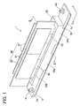
- Fig. 1 is an oblique view of an ink jet head of a first embodiment.
- an ink jet head 1 of a first embodiment has a long shape in an X direction.
- the ink jet head 1 has, in sequence from below, a head body 1a, a reservoir unit 70, and a control unit 80.
- the constituent elements of the inkjet head 1 will be described in sequence from above.
- reference numeral 52 represents a lower cover.
- a sheet that is to be printed by the ink jet head 1 will pass below the ink jet head 1 in the Y direction.
- the width of the sheet in the X direction is shorter than the length of the ink jet head 1 in the X direction.
- the ink jet head 1 can simultaneously print across the entire width of the sheet in the X direction. Because the sheet passes below the ink jet head 1 in the Y direction, the ink jet head 1 can print on the entire area of the sheet.
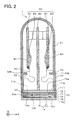
- the control unit 80 will be described with reference to Fig. 1 and Fig. 2.
- the control unit 80 comprises one main board 82, a total of four sub-boards 81, a total of 4 driver ICs 84, and a total of 4 FPCs (Flexible Printed Circuits) 50.
- the main board 82 and the sub-boards 81 have rectangular planar surfaces extending in the X direction, and are erected in parallel with each other.
- the main board 82 is fixed to the upper surface of the reservoir unit 70.
- the sub-boards 81 are spaced apart from both sides of the main board 82. Two of the sub-boards 81 are provided on one side of the main board 82.
- the main substrate 82 and each sub-board 81 are electrically connected to each other by means of connectors.
- the FPCs (Flexible Printed Circuits) 50 are members in which a wiring pattern is formed on a flexible insulation film, and the upper end of each FPC 50 is connected to the corresponding sub-board 81.
- One driver IC 84 is fixed to the central portion of each FPC 50.
- the lower end of each FPC 50 is connected to each actuator unit 21 described below.
- Each driver IC 84 is thermally bonded to the sub-board 81 via a heat sink 83.
- a master control board is provided in an ink jet printer not shown in the drawings. That master control board and the main control board 82 are connected by an FPC that is not shown in the drawings.
- Signals that are transmitted by the master control board installed in the ink jet printer are transmitted to the four driver ICs 84 via the main board 82, the four sub-boards 81, and the four FPCs 50.
- Each driver IC 84 produces drive signals for the corresponding actuator unit 21, and outputs them to the corresponding actuator unit 21 via the FPCs 50.
- the four actuator units 21 operate in accordance with the control signals of the master control board installed in the ink jet printer.
- the driver ICs 84 generate heat, when they operate. The heat generated by the driver ICs 84 is transmitted to the sub-boards 81 via the heat sinks 83, and is dissipated from the sub-board 81.
- the lower cover 52 is arranged on the ink jet head 1.
- An upper cover 51 is fitted on the upper portion of the lower cover 52.
- the control unit 80 is capped by the lower cover 52 and the upper cover 51. Ink that has become airborne during printing will be prevented from adhering to the control unit 80 etc. by means of the covers 51, 52.
- the upper cover 51 is omitted so that the control unit 80 is visible.
- the upper cover 51 has an arch-shaped ceiling, and caps the control unit 80.
- the lower cover 52 is a substantially square tubular shape that is open vertically, and caps the lower portion of the main substrate 82.
- the FPCs 50 are in a relaxed state within the space that is capped by the lower cover 52.
- Two projections 52a that project downward are formed on each of the lower ends of both lateral walls of the lower cover 52 along the length thereof (only one lateral wall is shown in Fig. 1). As will be described below with reference to Fig. 4, two recesses 53 are formed on each side of the reservoir unit 70 along the length thereof. As shown in Fig. 2, each projection 52a is accommodated within the corresponding recesses 53 of the reservoir unit 70.
- the FPCs 50 pass through the gaps between the projections 52a and the recesses 53.
- the tips of the projections 52a face a passage unit 4 described below. There is a relationship that gaps are formed between the tips of the projections 52a and the passage unit 4.
- the lower end portions of the FPCs 50 that are pulled through the gaps between the projections 52a and the recesses 53 extend horizontally along the upper surfaces of the actuator units 21.
- the lower end portions of the FPCs 50 are connected to the upper surfaces of the actuator units 21.
- a total of four actuator units 21 are fixed to the upper surface of one passage unit 4.
- One FPC 50 is connected to one actuator unit 21.
- One driver IC 84 and one sub-board 81 are connected to one actuator unit 21 through one FPC 50.
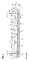
- Fig. 2 and Fig. 3 a cross-sectional display of the below-described passage unit 4 is omitted.
- the scale in the vertical direction is increased for ease of explanation.
- structures that do not originally appear in the same cross-section are also shown as needed for ease of explanation.
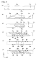
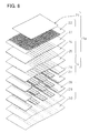
- the reservoir unit 70 is constructed of a total of 6 plates 71, 72, 73, 74, 75, 76 shown in Fig. 4(a), (b), (c), (d), (e), (f) by stacking them as shown in Fig. 3.
- the uppermost first plate 71 has a thickness that is larger than the other plates, is slightly longer than the other plates, and both ends thereof in the lengthwise direction project outward.
- round holes 71a, 71b are respectively formed by etching or the like in the vicinity of both ends in the lengthwise direction of the first plate 71.
- the round hole 71a is an ink introduction port for introducing ink to the ink jet head 1, and as shown in Fig. 1, will be fixed later to an ink supply joint 91.
- the round hole 71b is an ink discharge port for discharging ink from the ink jet head 1, and as shown in Fig. 1, will be fixed later to an ink discharge joint 92.
- a second plate 72 that is second from the top comprises a long narrow portion 72a that extends diagonally from a portion that corresponds to the round hole 71a formed in the first plate 71, a through hole 72b that is formed in a substantially parallelogram shape in approximately the central position of the second plate 72, and a long narrow hole 72c that extends diagonally toward the round hole 71b formed in the first plate 71.
- the through hole 72b forms an ink storage chamber that is positioned upstream of a filter 73f described below.
- a third plate 73 that is third from the top has a through hole 73b that is slightly smaller than the through hole 72b, in a position that corresponds to the through hole 72b formed in the second plate 72.
- a step 73a is formed in the upper edge of the through hole 73b, and the filter 73f that removes dirt and the like in the ink is provided on the step 73a (see Fig. 3).
- the filter 73f is fitted into the step 73a, and has a thickness that is substantially the same as the height of the step 73a.
- the upper surface of the filter 73f is on the same plane as the upper surface of the third plate 73.
- a round hole 73c is formed in the third plate 73 in a position that corresponds to the long narrow hole 72c formed in the second plate 72.
- the round hole 73c corresponds to one end of the long narrow hole 72c
- the round hole 71b corresponds to the other end of the long narrow hole 72c.
- a through hole 74a is formed in a fourth plate 74 that is fourth from the top by press working or the like.
- the through hole 74a forms an ink storage chamber that is positioned downstream of the filter 73f.
- the planar shape of the through hole 74a extends along the X direction so as to curve and become tapered, and is symmetrical with respect to the center thereof.
- the through hole 74a that forms the downstream ink storage chamber includes a main passage 74b that extends in the X direction, and 8 branch passages 74c that branch from the main passage 74b and which have a passage width that is narrower than the main passage 74b.
- Each pair of branch passages 74c extends in the same direction.
- Two branch passages 74c that extend on the bottom left side extend from the bottom left side of the main passage 74b
- two branch passages 74c that extend on the upper left side extend from the upper left side of the main passage 74b
- two branch passages 74c that extend on the bottom right side extend from the bottom right side of the main passage 74b
- two branch passages 74c that extend on the upper right side extend from the upper right side of the main passage 74b
- the main passage 74b extends in a position that corresponds to the round hole 73c of the third plate 73.
- the fifth plate 75 that is the fifth from the top is extremely thin compared to the other plates.
- a total of 10 elliptical holes 75a are formed by means of etching etc. in the fifth plate 75.
- the elliptical holes 75a are formed in positions that correspond to both ends in the lengthwise direction of the main passage 74b that is formed by the fourth plate 74, and in positions that correspond to the tips of each branch passage 74c.
- Five elliptical holes 75a each are formed on both sides of the fifth plate 75 in the Y direction near both ends.
- a sequence of one elliptical hole 75a, two elliptical holes 75a, and two elliptical holes 75a, are provided on the upper edge in the Y direction from one end in the lengthwise direction (the left side of Fig. 4(e)).
- a sequence of one elliptical hole 75a, two elliptical holes 75a, and two elliptical holes 75a, are provided on the lower edge in the Y direction from one end in the lengthwise direction (the right side of Fig. 4(e)).
- a total of 10 elliptical holes 75a are formed in positions that avoid cut-outs 53e.
- the ten elliptical holes 75a are symmetrically provided with respect to the center of the plate.
- the sixth plate 76 of the lowermost layer has 10 elliptical holes 76a that correspond to the 10 elliptical holes 75a formed in the fifth plate 75, and a through hole 76b that corresponds to the main passage 74b of the fourth plate 74.
- the lower surface of the sixth plate 76 is formed by half-etching or the like so that only the peripheral portions of the elliptical holes 76a project downward (the portion surrounded by the dotted line in the figure), only the projecting portions thereof are fixed to the upper surface of the passage unit 4, and the portions thereof other than the projecting portions are isolated from the passage unit 4 (see Fig. 2).
- rectangular cut-outs 53a, 53b, 53c, 53d, 53e, 53f are formed in a staggered pattern in both sides in the Y direction of each plate 71-76. Two of each of the cut-outs 53a, 53b, 53c, 53d, 53e, 53f are formed on one side, for a total of 4.
- recesses 53 are constructed (see Fig. 2) that run through the reservoir unit 70 in the vertical direction by means of these cut-outs 53a-53f.
- the width of the reservoir unit 70 is substantially the same as the width of the passage unit 4, excluding the recesses 53.
- the six plates 71-76 are stacked in an aligned state, and are fixed to each other.
- an ink supply joint 91 is fixed to a position that connects with the round hole 71a of the upper surface of the first plate 71.
- An ink discharge joint 92 is fixed in a position that connects with the round hole 71b of the upper surface of the first plate 71.
- the joints 91, 92 are both cylindrical members having base ends 91b, 92b whose outer diameters are slightly larger, and the respective openings of the cylindrical spaces 91a, 92a in the lower surfaces of the base ends 91b, 92b are fixed in positional relationships that match the openings in each round hole 71a, 71b of the first plate 71.
- the ink that has flowed through the cylindrical space 91a of the supply joint 91 and into the round hole 71a will flow into one end of the long narrow portion 72a, move horizontally from there, and will flow into the ink storage chamber 72b that is upstream of the filter 73f. Then the ink will pass through the filter 73f, and flow into the approximate central position of the ink storage chamber 74a that is downstream of the filter 73f. After that, as shown with the arrows in Fig. 4(d), the ink will move from the approximate center of the main passage 74b toward both ends in the lengthwise direction thereof, and toward the tips of each branch passage 74c.
- the round hole 71a of the first plate 71 forms an ink introduction port of the ink jet head 1.
- the long hole 72a of the second plate 72 forms an common ink passage that introduces ink to the common ink storage chamber.
- the through hole 72b of the second plate 72 forms the common ink storage chamber that is upstream of the filter.
- the through hole 74a of the fourth plate 74 forms the common ink storage chamber that is downstream of the filter.
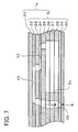
- the head body 1a will be described with reference to Fig. 2, Fig. 5, Fig. 6, Fig. 7, and Fig. 9. Note that in Fig. 6, the pressure chambers 10 and the apertures 12 that are below the actuator unit 21 should be drawn with broken lines, but are drawn with solid lines for ease of explanation.
- the head body 1a includes the passage unit 4, and four actuator units 21 that are fixed to the upper surface of the passage unit 4.
- the actuator units 21 select a pressure chamber 10 from the plurality of pressure chambers 10 formed in the upper surface of the passage unit 4, and pressurize the ink within the selected pressure chamber 10.
- the passage unit 4 will be described. As shown in Fig. 2, the passage unit 4 is substantially the same width as the reservoir unit 70, and as shown in Fig. 3, the length thereof in the X direction is slightly shorter than the reservoir unit 70.
- the passage unit 4 has a substantially rectangular shape.
- an ink discharge area in which a plurality of nozzles 8 are provided in a matrix shape is formed in the lower surface of the passage unit 4.
- a plurality of pressure chambers 10 are provided in a matrix shape in the upper surface of the passage unit 4.
- the number of nozzles 8 is equal to the number of pressure chambers 10.
- One nozzle 8 corresponds to one pressure chamber 10
- one pressure chamber 10 corresponds to one nozzle 8.
- the passage unit 4 is constructed from 9 metal plates, that are in sequence from the top, a cavity plate 22, a base plate 23, an aperture plate 24, a supply plate 25, manifold plates 26, 27, 28, a cover plate 29, and a nozzle plate 30.
- the plates 22-30 have long rectangular planes in the X direction (see Fig. 1).
- a total of 10 through holes that form the 10 reception ports 5b, and a large number of substantially rhombic through holes that form the pressure chambers 10, are formed in the cavity plate 22.
- holes that connect each pressure chamber 10 with each actuator 12, and holes that connect each pressure chamber 10 with each nozzle 8, are formed in the base plate 23.
- holes that connect the reception ports 5b with the manifold passages 5 are also formed in the base plate 23.
- Through holes that form the apertures 12 that connect with each pressure chamber 10, and holes that connect the pressure chamber 10 and the nozzle 8, are formed in the aperture plate 24.
- holes that connect the reception ports 5b with the manifold passages 5 are also formed in the aperture plate 24.
- Holes that connect the apertures 12 with the sub-manifold passages 5a, and holes that connect the pressure chambers 10 with the nozzles 8, are formed in the supply plate 25. Although not illustrated in Fig. 7, holes that connect the reception ports 5b with the manifold passages 5 are also formed in the supply plate 25. Through holes that mutually connect when stacked and which construct the manifold passages 5 and the sub-manifold passages 5a, and holes that connect the pressure chambers 10 and the nozzles 8, are formed in the manifold plates 26, 27, 28. Holes that connect the pressure chambers 10 and the nozzles 8 are formed in the cover plate 29. Holes that form the nozzles 8 that connect with the pressure chambers 10 are formed in large numbers in the nozzle plate 30. As shown in Fig.
- the 10 reception ports 5b are open in positions that correspond to the 10 elliptical holes 76a (see Fig. 4(f)) of the reservoir unit 70 in the upper surface of the passage unit 4.
- the manifold passages 5 that connect with the reception ports 5b, and the sub-manifold passages 5a that branch from the manifold passages 5, are formed within the passage unit 4.
- an individual ink passage 32 is formed from the sub-manifold passage 5a, through the pressure chamber 10, and to the nozzle 8.
- Ink that is supplied from the reservoir units 70 through the reception ports 5b to the inside of the passage unit 4 is branched from the manifold passages 5 to the sub-manifold passages 5a, and through the apertures 12 and pressure chambers 10, to the nozzles 8.
- the manifold passages 5 are branched into 10 passages, and the sub-manifold passages 5a are branched into an even larger number of passages, but mutually connect within the reservoir unit 70. In other words, all of the manifold passages 5 and the sub-manifold passages 5a merge together in a downstream ink storage chamber 74a.
- the manifold passages 5 and the sub-manifold passages 5a are thickly formed so that a large quantity of ink will flow, and the pressure drop will be low. In other words, the pressure of the ink that is stored in the manifold passages 5 and the sub-manifold passages 5a is almost the same regardless of location. In contrast, the individual ink passages 32 are narrow, and the pressure drop is large. Because of this, the ink pressure may differ in each individual ink passage 32.
- the manifold passages 5 and the sub-manifold passages 5a can act as an common ink storage space that commonly stores ink that is to flow to the plurality of individual ink passages 32.
- a common upstream ink storage chamber 72b is formed within the reservoir unit 70
- a first common downstream ink storage chamber 74a is formed within the reservoir unit 70
- second common downstream ink storage chambers 5, 5a are formed within the passage unit 4, and can be evaluated.
- each actuator unit 21 is trapezoidal.
- the four actuator units 21 are fixed to the upper surface of the passage unit 4.
- the four actuator units 21 are provided in a staggered formation.
- the reception ports 5b are formed in positions that do not overlap with the four actuator units 21.
- the four actuator units 21 are fixed in positions that correspond to ink jet areas that are formed on the bottom surface of the passage unit 4.
- a large number of nozzles are formed in the ink jet areas.
- a large number of recesses that respectively form the pressure chambers 10 are formed in the upper surface of the passage unit 4 that corresponds to the ink jet area.
- one nozzle 8 corresponds to one recess 10.
- One actuator unit 21 extends along a plurality of recesses or pressure chambers, and caps each of the recesses. By capping the recesses with the actuator unit 21, the pressure chambers 10 will be formed.
- Each actuator unit 21 is fixed so that the opposing parallel edges thereof extend along the lengthwise direction of the passage unit 4. The diagonal edges of adjacent actuator units 21 extend in parallel across a slight gap. As shown in Fig. 2, the actuator units 21 are separated from the lower surface of the reservoir unit 70.
- a corresponding FPC 50 is fixed to the upper surface of each actuator unit 21. The FPCs 50 are inserted into the gap between the actuator units 21 and the reservoir unit 70.
- the actuator units 21 are constructed from 4 piezoelectric sheets 41, 42, 43, 44 that are approximately 15 ⁇ m in thickness, and are composed of a lead zirconate titanate (PZT) type ceramic material having ferroelectric characteristics.
- the piezoelectric sheets 41-44 are fixed together.
- a plurality of individual electrodes 35 are formed on the upper surface of the uppermost piezoelectric sheet 41. Each individual electrode 35 is formed in a position that corresponds to a recess that forms a pressure chamber 10.
- a common electrode 34 of approximately 2 ⁇ m in thickness is interposed between the uppermost piezoelectric sheet 41 and the piezoelectric sheet 42 below, and formed on the entire surface of the sheet.
- the individual electrodes 35 and the common electrode 34 are composed of a metal material such as an Ag-Pd complex or the like. Electrodes are not provided between the piezoelectric sheets 42, 43, the piezoelectric sheets 43, 44, and on the lower surface of the piezoelectric sheet 44.
- the individual electrodes 35 have a thickness of approximately 1 ⁇ m, and have a substantially rhombic planar shape that resembles that of the pressure chambers 10.
- One end of the acute angle portions of the substantially rhombic individual electrodes 35 is extended, and round lands having a diameter of approximately 160 ⁇ m and electrically connected to the individual electrodes 35 are provided on the tip thereof.
- the lands 36 are composed of a metal that contains, for example, glass frit.
- the lands 36 are arranged in positions that do not overlap with the pressure chambers 10.
- the lands 36 are electrically bonded with the contact points provided on the FPCs 50 (see Fig. 2).
- the common electrode 34 is grounded in an area that is not illustrated. In this way, the common electrode 34 is maintained in a uniform ground potential in the entire area that corresponds to the pressure chambers 10.
- the individual electrodes 35 are connected to the driver ICs 84 through the lands 36 that are independent of each individual electrode 35, and the FPCs 50 that are comprised of lead wires that are independent of each individual electrode 35 (see Fig. 2), so that the electric potential can be controlled independent from other individual electrodes 35.
- a large number of individual electrodes 35 can be formed at a high density on the piezoelectric sheet 41. Because of that, the pressure chambers 10 and the nozzles 8 that are formed in positions that correspond to the individual electrodes 35 can be provided at a high density. High resolution image printing can be performed.
- the piezoelectric sheet 41 When the piezoelectric sheet 41 is polarized in the thickness direction, makes the electric potential of the individual electrodes 35 different than the common electrode 34, and applies an electric field in the thickness direction of the piezoelectric sheet 41, the electric field application portion in the piezoelectric sheet 41 is deformed due to the piezoelectric effect.
- the piezoelectric sheet 41 When an electric field is applied in the thickness direction of the piezoelectric sheet 41 that is polarized in the thickness direction, the piezoelectric sheet 41 will become thicker, and will contract within the planar surface.
- the remaining three piezoelectric sheets 42-44 are non-active layers, and cannot naturally deform.
- the actuator units 21 are a so-called unimorph type, in which the one piezoelectric sheet 41 that is furthest away from the pressure chambers 10 is the active layer, and the three piezoelectric sheets 42-44 on the side near the pressure chambers 10 are non-active layers.
- the piezoelectric sheets 41-44 are fixed to the upper surface of the cavity plate 22 that forms the pressure chambers 10. The entirety of the piezoelectric sheets 41-44 will deform (unimorph deformation) so as to become convex on the pressure chambers 10 side, because the electric field application portion of the piezoelectric sheet 41 will warp, and the piezoelectric sheets 42-44 below will not warp.
- the volume of the pressure chambers 10 will decrease.
- the pressure applied to the ink within the pressure chambers 10 will rise, the ink will be pushed out from the pressure chambers 10 to the nozzles 8, and the ink will jet from the nozzles 8.
- the piezoelectric sheets 41-44 will take their original flat shape, and the volume of the pressure chambers 10 will return to their original volume.
- ink will be introduced from the manifold passages 5 to the pressure chambers 10, and ink will be again stored within the pressure chambers 10.
- the nozzles that will jet the ink can be selected.
- the timing at which the ink is jetted from the nozzles can be controlled.
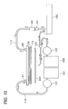
- FIG. 10 the system that supplies ink from the ink supply joint 91 to the reservoir unit 70, and the system that discharges ink stored in the reservoir unit 70 from the ink discharge joint 92, will be described with reference to Fig. 10.
- An ink tank 101 is prepared on the exterior of the reservoir unit 70.
- the ink tank 101 and the ink supply joint 91 are connected by a tube 110.
- a pump 121 is interposed along the length of the tube 110. When the pump 121 rotates, as shown with the solid black arrow of Fig. 10, the ink will pass from the ink tank 101 to the pump 121, the tube 110, and the ink supply joint 91, and be supplied to the inside of the reservoir unit 70.
- the pump 121 will first operate when the ink is to be supplied to the inside of the reservoir unit 70.
- a bypass passage is maintained inside the pump 121, and the ink can pass through the pump 121 when the pump 121 is not operating.
- the pump 121 is not operated during normal printing operations.
- negative pressure will be generated inside the passage unit 4, and that will be transmitted to the ink tank 101 through the reservoir unit 70 and the tube 110. Due to that negative pressure, the ink will be drawn out from the ink tank 101, and will be drawn into the reservoir tank 70 through the bypass passage within the pump 121, and the tube 110.
- the ink quantity that is supplied to the combined unit of the reservoir unit 70 and the passage unit 4 (this is referred to as a body) will be equal to the ink quantity that is jetted from the body.
- the flow of ink may be slow, and when viewed in short time intervals, the supply quantity and the jetted quantity of the ink may not necessarily match. If there is a time period in which the supply quantity is greater than the jetted quantity, there will also be a time period in which the supply quantity is less than the jetted quantity. This will produce pressure fluctuations inside the body.
- a tube 111 is connected to the ink discharge joint 92.
- a discharge valve 60 is connected to the tip of the tube 111.
- a plunger 65 is provided is provided adjacent to the discharge valve 60.
- the tube 111 and the plunger 65 are provided on both sides of the discharge valve 60.
- the discharge valve 60 is switched between open and closed states by means of the up and down movement of the plunger 65.
- the discharge valve is opened by means of the plunger 65, ink will be allowed to discharge from the reservoir unit 70.
- the discharge valve is closed by means of the plunger 65, ink will be prevented from discharging from the reservoir unit 70.
- the tube 111 will be filled with ink.
- the tube 111 also forms a portion of the ink storage space.
- the discharge valve 60 is opened by means of the plunger 65, as shown with the hollow white arrow of Fig. 10, the ink inside the reservoir unit 70 will pass through the discharge joint 92 and the tube 111, will pass through the passages inside the discharge valve 60 and the plunger 65, and will be discharged to a waste liquid tank 103.
- a reverse purge means ejecting ink or cleaning ink from the nozzles 8 under pressure, and discharging ink from the ink jet head 1 after the ink has flowed in the direction opposite from the normal direction for normal printing operation.
- the interior of the ink jet head 1 can be cleaned. In other words, foreign material such as dust, air bubbles, and the like that accumulate inside the ink jet head 1 can be removed.
- the lower portion of the ink jet head body 1a is capped with a cap 200 (more particularly, the entire lower surface on which the nozzles 8 of the passage unit 4 are formed). Then, as shown with one dotted arrow in Fig. 10, cleaning ink inside a cleaning ink tank 102 will be ejected under pressure from the cap 200, and into the passage unit 4 of the head body 1a through the pump 122 and a branching valve 123.
- the cleaning ink injected into the passage unit 4 will flow into the individual ink passages 32 shown in Fig. 7 in the opposite direction of the arrows.
- the cleaning ink will move from the nozzles 8, through the pressure chambers 10, the apertures 12, the sub-manifold passages 5a, and the manifold passages 5 shown in Fig. 5, and to the reception ports 5b.
- the cleaning ink will also flow from the reception ports 5b into the reservoir unit 70.
- the cleaning ink that has flowed into the reservoir unit 70 will reach the elliptical holes 76a, the elliptical holes 75a, and the downstream ink storage chamber 74a.
- the cleaning ink will pass through the round hole 73c, the long narrow hole 72c, and the round hole 71b, will reach the discharge joint 92, and will be discharged from the discharge joint 92.
- the ink that is in the passage unit 4 and the reservoir unit 70 will be pushed by the cleaning ink and will be discharged together with the cleaning ink.
- the ink discharged from the reservoir unit 70 in this way and the cleaning ink will be discharged to the waste liquid tank 103 through the passage shown with the hollow white arrow in Fig. 10.
- Ink will be filled from the round hole 73c facing the downstream ink storage chamber 74a, to the long narrow hole 72c, the round hole 71b, the discharge joint 92, the tube 111, and the discharge valve 60, and this will become a portion of the ink storage space that is prepared in the ink jet head 1.
- the ink storage space is also used as the ink discharge passage.
- the double dotted arrows in Fig. 10 show the flow of the ink during a purge.
- a purge is forcibly discharging ink contaminated with foreign matter inside the nozzles 8, and in this way ink discharge from the nozzles 8 will be maintained in a good condition.
- Purges include a pressure purge that pressurizes the ink inside the head 1, and a drawing purge that draws ink inside the head 1. Ink that is discharged from the nozzles 8 is received in the cap 200, and then is discharged to the waste liquid tank 103 via the branching valve 123.
- the discharge valve 60 includes a valve body 61, and a cap 62 that fits on the lower portion of the valve body 61.
- the valve body 61 has a round flat upper wall 61a having a round hole in the center thereof, a tubular outer peripheral wall 61b and an inner peripheral wall 61c that extend downward from the upper wall 61a, and a tubular extension 61d that extends upward from the edge of the round hole of the upper wall 61a.
- a substantially column-shaped passage 60x is formed within the extension 61d and the inner peripheral wall 61c.
- the inner peripheral wall 61c tapers toward the upper end thereof, and thus the cross-section of the passage 60x will increase in size toward the lower end of the inner peripheral wall 61c.
- the cap 62 has a through hole 62a that passes therethrough in the direction in which the passage 60x extends.
- An air chamber 60y that captures air is formed between the outer peripheral wall 61b and the inner peripheral wall 61c.
- the air chamber 60y is an annular shape that is provided around the passage 60x.
- the upper portion of the annular space of the air chamber 60y between the tubular outer peripheral wall 61b and the inner peripheral wall 61c is formed by sealing with the upper wall 61a.
- a recess is formed in the edge of the through hole 62a in the upper surface of the cap 62 in order to provide an O-ring 65.
- a ball valve 64 is provided on the O-ring 65, and a spring 63 is provided on the ball valve 64.
- the spring 63 is inside the passage 60x of the valve body 61, wound so as to have substantially the same tubular outer diameter as the extension 61d, and urges the ball valve 64 downward.
- the lower end of the passage 60x is sealed by the ball valve 64.
- the air chamber 60y is connected through a gap 60z to the passage 60x that is closed by the ball valve 64.
- the gap 60z is the connection point between the air chamber 60y and the ink storage space 60x.
- the air chamber 60y extends upward from the gap 60z. In other words, the air chamber 60y extends from the gap 60z in a direction that is opposite to the flow of the ink downward toward the passage 60x. Because the air chamber 60y extends upward from the gap 60z, the ink cannot penetrate into the air chamber 60y. Because the air chamber 60y extends from the gap 60z in the direction that is opposite of the flow of ink, even if the ink flows, the ink cannot penetrate into the air chamber 60y. The air chamber 60y maintains an air within the ink that is fills the sealed space. Captured air within the air chamber 60y is compressible, and the volume thereof is easily changed.
- the air that fills the air chamber 60y will be compressed, and the volume that the ink fills will increase. As a result, the pressure applied to the ink will be prevented from rising excessively. If the pressure of the ink that fills the sealed space decreases, the air that fills the air chamber 60y will expand, and the volume that the ink fills will decrease. As a result, the pressure applied to the ink will be prevented from decreasing excessively.
- the air that fills the air chamber 60y will effectively reduce the range of fluctuation of the pressure applied to the ink. This is referred to as a damper effect.
- the plunger 65 includes a plunger body 66, and a pipe 67 that is fitted on the upper portion of the plunger body 66.
- the plunger body 66 has an end wall 66a having a round hole in the center, and a pipe 66b that extends downward from the end wall 66a.
- a substantially column-shaped passage 65x is formed within the end wall 66a and the pipe 66b.
- the pipe 67 is fitted into the round hole in the center of the end wall 66a, and an O-ring 68 is provided on the outer periphery of the pipe 67 on the upper surface of the end wall 66a.
- Two cut-outs 67a are formed in the upper end of the pipe 67 (only one is shown in Fig. 11(b)).
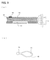
- Fig. 12 is a vertical cross-section showing the plunger 65 of Fig. 11(b) fitted into the lower portion of the discharge valve 60 of Fig. 11(a), with Fig. 12 (a) showing the plunger 65 in the discharge prohibited position, and Fig. 12 (b) showing the plunger 65 in the discharge permitted position.
- the plunger 65 When a reverse purge is performed, the plunger 65 is moved upward by a mechanism that includes an electromagnetic valve 130 described in detail below (see Fig. 13), and is placed in the discharge permitted position as shown in Fig. 12 (b). In the movement stage, the upper end of the pipe 67 of the plunger 65 will come into contact with the ball valve 64, resist the urging force of the spring 63, and move the ball valve 64 upward. Then, the plunger 65 is stopped in the position in which the end wall 66a contacts the cap 62 of the discharge valve 60 through the O-ring 68.
- an electromagnetic valve 130 described in detail below
- Fig. 13 (a) corresponds to Fig. 12 (a)
- Fig. 13 (b) corresponds to Fig. 12 (b).
- a base 140 is provided in a recording device that is comprised of the ink jet head 1 of the present embodiment.
- a valve support unit is formed on the base 140.
- the discharge valve 60 is fixed on the valve support unit 139.
- the electromagnetic valve 130 is fixed to the upper surface of the base 140.
- the electromagnetic valve 130 has a slidable portion 130a that is fixed to one end of a shaft 131.
- An L-shaped arm 132 is supported on a lateral surface of the base 140.
- the L-shaped arm 132 has a cut-out 132b formed in one end side from the bend, and a cut-out 132a formed on the other end.
- the shaft 133 is provided inside the cut-out 132b, and the L-shaped arm 132 is pivotably supported on the base 140 with the shaft 133 as the center thereof.
- the shaft 131 of the electromagnetic valve 130 is provided inside the cut-out 132a of the other end.
- the L-shaped arm 132 supports the plunger 65 on one end 132c.
- the other end 132a of the L-shaped arm 132 will also move, in accordance with the movement of the shaft 131. In this way, the L-shaped arm 132 will pivot about the shaft 133, and the plunger 65 supported on the one end 132c of the L-shaped arm 132 will move up and down.
- Fig. 13 (a) by placing the plunger 65 in the discharge prohibited position described above, and sliding the slidable portion 130a in the direction of the arrow toward the interior of the electromagnetic valve 130 to pivot the L-shaped arm 132 in the clockwise direction in the drawing, the state shown in Fig. 13(b), i.e., the state in which the plunger 65 is in the discharge permitted position described above, can be achieved.
- the ink jet head 1 With the ink jet head 1 according to the present embodiment, a quantity of ink can only be supplied from the ink tank 101 in accordance with the jetted quantity of ink, and thus the ink volume inside the ink jet head 1 may temporarily decrease. In contrast, excess ink may attempt to flow from the ink tank 101 into the ink jet head 1. Due to this, the pressure applied to the ink inside the ink jet head 1 will fluctuate. With the ink jet head 1 of the present embodiment, if the pressure of the ink inside the ink jet head 1 increases, the air that fills the air chamber 60y will compress, and the volume that the ink fills will increase. As a result, the pressure applied to the ink will be prevented from rising excessively.
- the air chamber 60y for obtaining the damper effect is formed on the exterior of the body that is a combination of the passage unit 4 and the reservoir unit 70. Therefore, the construction of the body can be simplified.
- the air chamber 60y may also be formed inside the body.
- the air chamber 60y is connected to the ink discharge passage.
- the air chamber 60y may be connected to the upstream ink storage chamber 72b, and may be connected to the downstream ink storage chamber 74a.
- the air chamber 60y may be connected anyplace from the ink introduction port 71a to the sub-manifolds 5a.
- the fifth plate 75 that is a portion of the wall that defines the downstream ink storage chamber 74a of the reservoir unit 70 is extremely thin, and can deform in response to the pressure inside the ink jet head 1. As shown in Fig. 4(e), (f), the fifth plate 75 can easily deform up and down because the through hole 76b is formed in the sixth plate 76.
- the extremely thin fifth plate 75 is also used as an adjustor that will allow the volume of the downstream ink storage chamber 74a to change.
- the air chamber 60y operates as a first adjustor
- the extremely thin fifth plate 75 operates as a second adjustor. Because two adjustors are prepared, the pressure fluctuations produced inside the ink jet head 1 can be effectively controlled or suppressed.
- an adjustor that allows the volume of the ink storage space to change can be formed by forming the tube 111 or a portion thereof with a resilient material.
- the discharge valve 60 when one wants to remove foreign matter such as dust, air bubbles, and the like that are in the ink jet head 1, the ink inside the head 1 can be easily discharged by opening the lower end of the ink passage 60x with the discharge valve 60. Because the discharge valve 60 is a construction having the ball valve 64 that can seal the lower end of the ink passage 60x, and the spring 63 that will urge the ball valve 64 downward, a discharge valve 60 construction that is simplified and lower in manufacturing cost can be achieved.
- a supply valve is preferably provided between the pump 121 shown in Fig. 10 and the ink supply joint 91.
- the reservoir unit 70 has the filter 73fthat divides the upstream ink storage chamber 72b and the downstream ink storage chamber 74a.
- the discharge path is connected to the downstream ink storage chamber 74a. Because foreign matter in the downstream ink storage chamber 74a can be discharged, the foreign matter can be prevented from moving to the passage unit 4 and causing poor ink discharge. Instead of this, the discharge chamber may be connected to the upstream ink storage chamber 72b. In this situation, the filter 73f can be cleaned because cleaning ink will reverse flow through the filter 73f.
- the air chamber 60y that achieves the damper effect, and the extremely thin fifth plate 75 control fluctuations in the pressure of the ink stored in the downstream ink storage chamber 74a.
- the ink jet head of the present embodiment has a damper passage pipe 160 shown in Fig. 14 installed on the discharge tube 111 shown in Fig. 10.
- the other points thereof are identical with the first embodiment.
- the damper passage pipe 160 will be described below. Note that in this situation, the discharge valve 60 need not have the air chamber 60y.
- the damper passage pipe 160 includes a pipe body, and a damper sheet 162 that is composed of a thin, flexible sheet material that is installed on the pipe body 161.
- the pipe body 161 has a round and flat upper wall 161a and lower wall 161c that have a round hole in the centers thereof, a tubular peripheral wall 161b that is connected with the outer peripheral edges of the upper wall 161a and the lower wall 161c on the upper end and lower end thereof, an tubular upward extending portion 161d that extends upward from the edge of the round hole of the upper wall 161a, and a tubular downward extending portion 161e that extends downward from the edge of the round hole of the lower wall 161c.
- a substantially circular hole 161z is formed in the peripheral wall 161b, and the passage 160x inside the damper path pipe 160 connects with the atmosphere through the hole 161z.
- the damper sheet 162 is installed on the inner surface of the peripheral wall 161b so as to cap the opening of the hole 161z, and is interposed between the ink inside the passage 160 and the atmosphere. More particularly, the damper sheet 162 has a circular flat surface that is slightly larger than the hole 161z, and only the peripheral edge 162a is fixed to the peripheral wall 161b to surround the hole 161z.
- the portion of the damper sheet 162 other than the edge 162a projects, as shown in Fig. 14(a), on the inner side of the passage 160x, and in this situation forms two convex portions.
- the inside of the passage 160x is filled with ink at this time, and an excessively negative pressure is not produced inside the head 1.
- the portion of the damper sheet 162 that projects on the inner side of the passage 160x will be pulled further inward and, as shown in Fig. 14 (b), will deform so as to form one convex portion.
- the damper sheet 162 is installed on the inner surface of the peripheral wall 161b rather than the outer surface, a compact damper passage pipe 160 will be achieved.
- the damper sheet 162 is positioned inside the passage 160x, the problem of the damper 162 composed of a thin sheet material being damaged will be reduced, even if it is deformed in accordance with the pressure fluctuations inside the ink jet head 1.
- the peripheral wall 161b also functions as a limiter that limits the maximum deformation of the damper sheet 162.
- the damper sheet 162 may also be fixed to the outer surface of the peripheral wall 161b.
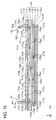
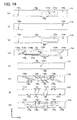
- the ink jet head of the present embodiment differs from the first embodiment only in the construction of the reservoir unit 170. The other portions thereof are the same as the first embodiment. Only the construction of the reservoir unit 170 will be described below. Note that in this situation, the discharge valve 60 need not have the air chamber 60y. In addition, for ease of explanation, the scale in the vertical direction in Fig. 15 is increased, and ink passages that are not visible in the same cross-section are shown as needed.
- the reservoir unit 170 is formed by stacking eight plates 171, 172, 173, 174, 175, 176, 177, 178 that have long square planar surfaces in the X direction.
- One plate 172 of eight plates is made of flexible sheet and works as a damper sheet.
- the first plate 171 that is the uppermost layer has a round hole 171a formed near one end in the lengthwise direction of the first plate 171, and a round hole 171b formed near the other end.
- the round hole 171a is positioned eccentrically below the center of the first plate 171 in the Y direction
- the round hole 171b is positioned eccentrically above the center of the first plate 171 in the Y direction.
- a long elliptically shaped recess 171c that extends in the X direction is formed in the lower surface of the first plate 171 (the surface on the damper sheet 172 side).
- the recess 171c is positioned between the central position in the X direction of the first plate 171, and the round hole 171b. Furthermore, a round hole 171d is formed in the bottom center of the recess 171c. In other words, the elliptically shaped recessed 171c is formed in the lower surface side of the first plate 171, and the round hole 171d is formed so as to pass through the bottom of the recess 171c and the upper surface of the first plate 171.
- a damper sheet 172 that is second from the top is composed of a thin flexible sheet material, and as shown in Fig. 15 and Fig. 16(b), round holes 172a, 172b are formed in positions that correspond to the round holes 171a, 171b formed in the first plate 171.
- the thin flexible sheet material may be one that easily bends in response to the pressure fluctuations in the ink, and may be metal or resin.
- a compound sheet made from resin is employed, in which a gas barrier sheet is provided on PET (polyethylene terephthalate) having good gas barrier characteristics. In this way, the transmission of air or vapors through the thin flexible sheet can be controlled. Because the sheet is flexible, it can also function well as a damper that controls the pressure fluctuations of the ink.
- the third plate 173 that is third from the top has round holes 173a, 173b that are formed in and pass through positions that correspond to the round holes 171a, 171b formed in the first plate 171, and the elliptical hole 173c that corresponds to the elliptical recess 171c formed in the first plate 171.
- the fourth plate 174 that is fourth from the top has long narrow recesses 174a, 174b formed on a top surface.
- the recesses 174a, 174b extend diagonally from positions that correspond to the round holes 171a, 171b of the first plate 171, toward the center of the fourth plate 174 in the X and Y direction.
- an elliptical recess 174c that connects with the long narrow recess 174a is formed on the top surface.
- the recess 174c extends to the center of the fourth plate 174.
- an elliptical recess 174f is formed on the top surface of the fourth plate 174.
- the recess 174f connects with the long narrow recess 174b and extends to the center of the fourth plate 174.
- the elliptical recess 174f is formed in a concave shape, has an outer shape and size that is substantially the same as the elliptical hole 173c of the third plate 173, and is open on the third plate 173 side.
- a damper connection port 174h is formed near the center of the fourth plate 174.
- the elliptical recess 174c and the elliptical recess 174f are mutually connected via the damper connection port 174h.
- an elliptical recess 174d that is slightly smaller than the elliptical recess 174c is formed in the bottom center of the elliptical recess 174c. Furthermore, a through hole 174e that is further slightly smaller than the elliptical recess 174d is formed in the bottom center of the elliptical recess 174d.
- a filter 174g that removes dirt and the like that is in the ink is provided on a step that is a part of the upper edge of the through hole 174e.
- the long narrow portion 174a, the elliptical recess 174c, and the elliptical recess 174d form an common ink storage chamber 181a that is upstream of the filter 174g.
- the elliptical recess 174f and the long narrow rcess 174b form the damper chamber 182.
- the damper chamber 182 referred to here is a chamber that functions to allow changes in volume, and to smooth out the changes in the pressure applied to the ink.
- the fifth plate 175 that is the fifth from the top has a round hole 175a that is formed in the center thereof. Note that the fifth plate 175 is stacked from below so that the round hole 175a connects with the through hole 174e of the fourth plate 174. In addition, the round hole 175a faces the center acute angular portion of the through hole 174e of the fourth plate 174.
- the sixth plate 176 that is the sixth from the top has a through hole 176a that is formed therein.
- the planar shape of the through hole 176a extends along the X direction so as to curve and become tapered, and is symmetrical with respect to the center thereof.
- the through hole 176a that forms the downstream ink storage chamber includes a main passage 176b that extends in the X direction, and 8 branch passages 176c that branch from the main passage 176b and which have a passage width that is narrower than the main passage 176b.
- Each pair of branch passages 176c extends in the same direction.
- the two branch passages 176c that extend on the lower left side extend from the lower left side of the main passage 176b
- the two branch passages 176c that extend on the upper left side extend from the upper left side of the main passage 176b
- the two branch passages 176c that extend on the lower right side extend from the lower right side of the main passage 176b
- the two branch passages 176c that extend on the upper right side extend from the upper right side of the main passage 176b.
- the seventh plate 177 that is the seventh from the top is extremely thin compared to the other plates.
- a total of 10 elliptical holes 177a are formed by means of etching etc. in the fifth plate 177.
- the elliptical holes 177a are formed in positions that correspond to both ends in the lengthwise direction of the main passage 176b that is formed by the sixth plate 176, and in positions that correspond to the tips of each branch passage 176c.
- Five elliptical holes 177a each are formed on both sides of the seventh plate 177 in the Y direction near both ends.
- a sequence of one elliptical hole 177a, two elliptical holes 177a, and two elliptical holes 177a, are provided on the upper edge in the Y direction from one end in the lengthwise direction (the left side of Fig. 16(g)).
- a sequence of one elliptical hole 177a, two elliptical holes 177a, and two elliptical holes 177a, are provided on the lower edge in the Y direction from one end in the lengthwise direction (the right side of Fig. 16(g)).
- a total of 10 elliptical holes 177a are formed in positions that avoid cut-outs 53g.
- the ten elliptical holes 177a are symmetrically provided with respect to the center of the plate.
- the eighth plate 76 of the lowermost layer has 10 elliptical holes 178a that correspond to the 10 elliptical holes 177a formed in the seventh plate 177, and a through hole 178b that corresponds to the main passage 176b of the sixth plate 176.
- the lower surface of the eighth plate 178 is formed by half-etching or the like so that only the peripheral portions of the elliptical holes 178a project downward (the portion surrounded by the dotted line in the figure), only the projecting portions thereof are fixed to the upper surface of the passage unit 4, and the portions thereof other than the projecting portions are separated from the passage unit 4 (see Fig. 2).
- the seven plates 171, 173-178, and the one damper sheet 172 are aligned together and stacked as shown in Fig. 15, and are fixed to each other.
- four rectangular cut-outs 53g-53m are formed in a staggered pattern along the lengthwise direction on both ends (two on each end) in the Y direction of each plate 171, 173-178.
- a supply joint 91 is fixed to the upper surface of the first plate 171 that corresponds to the round hole 171a.
- a discharge joint 92 is fixed to the upper surface of the first plate 171 that corresponds to the round hole 171b.
- the joints 91, 92 are tubular members having base ends 91b, 92b that are slightly larger than the outer diameter, and are provided so that the opening of the tubular space 91a in the lower surface of the base end 91b matches the round hole 171a of the first plate 171, and the opening of the tubular space 92a in the lower surface of the base end 92b matches the round hole 171b of the first plate 171.
- the ink flow within the reservoir unit 170 when ink is supplied thereto will be described.
- the flow of the ink from the supply joint 91 into the reservoir unit 170 (shown with the solid black arrows in Fig. 15) will be described.
- ink that has flowed into the round hole 171a through the tubular space 91a of the supply joint 91 will then flow through the round hole 172a and the round hole 173a to the upstream ink storage chamber 181a.
- the upstream ink storage chamber 181a is formed by the elliptical recess 174c formed in the fourth plate 174.
- the ink that has flowed into the upstream ink storage chamber 181a will flow through the filter 73f, and into the downstream ink storage chamber 181b.
- the downstream ink storage chamber 181b is formed by the elliptical hole 174e formed in the fourth plate 174.
- the ink that has flowed into the downstream ink storage chamber 181b will pass through the round hole 175a in the fifth plate 175, and into the approximate center of the main passage 176b of the sixth plate 176. After that, as shown with the arrows in Fig. 16(f), the ink will move from the approximate center of the main passage 176b toward both ends in the lengthwise direction thereof, and toward the tips of each branch passage 176c.
- the ink that has flowed into the upstream ink storage chamber 181a will flow through the damper connection port 174h, and into the damper chamber 182.
- the damper chamber 182 is formed by the elliptical hole 173c that is formed in the third plate 173, and the elliptical recess 174f that is formed in the fourth plate 174. Note that when the ink is first introduced, by discharging the ink that has flowed into the damper chamber 182 from the discharge joint 92 to the exterior, air bubbles in the upstream ink storage chamber 181a and the damper chamber 182 can be discharged. In other words, ink can be filled in a state in which there are no air bubbles in the space on the upstream side of the filter 174. Ink will be temporarily stored in the upstream ink storage chamber 181a and the downstream ink storage chamber 181b.
- the cleaning ink that has flowed into the upstream ink storage chamber 181a will, as shown with the hollow white arrows in the figure, pass through the damper chamber 182 and the round holes 173b, 172b, 171b, and be discharged from the discharge joint 92. At this time, the ink that is in the passage unit 4 and the reservoir unit 170 will be pushed out by the cleaning ink and will be discharged together with the cleaning ink. Foreign matter that has been captured by the filter 174g will also be discharged, and thus the cleanliness of the passages and the filter capabilities will be restored.
- the wall that defines the damper chamber 182 is formed by the damper sheet 172.
- the elliptical recess 171c faces the area that faces the elliptical hole 173c, and the damper sheet 172 is interposed therebetween.
- the space that is defined by the damper sheet 172 and the recess 171c is connected to the atmosphere by means of the round hole 171d.
- the damper sheet 172 is interposed between the ink inside the damper chamber 182 and the atmosphere.
- the damper sheet 172 is both deformable on the recess 171c side, and deformable on the elliptical hole 173c side. By deforming the damper sheet 172, the volume of the damper chamber 182 can be changed.
- the bottom of the recess 171c limits the excessive displacement of the damper sheet 172.
- the first plate 171 is a limiting member for limiting the displacement of the damper sheet 172. Note that the limiting member does not only limit the displacement of the damper sheet 172, but will also prevent external forces that lead to damage of the damper sheet 172 from being directly applied to the damper sheet 172. In this way, the handling of the ink jet head 1 will be easy, and will contribute to a longer lifespan.
- the damper sheet 172 will deform in response to pressure inside the ink jet head 1, and thus like with the first embodiment described above, pressure fluctuations that are produced in the ink jet head 1 will be controlled or suppressed. Because the pressure applied to the ink is stable, a stable quantity of ink can be jetted.
- the air chamber 60y When the air chamber 60y is provided on the discharge valve 60, it will function as a second volume adjustor. Because the oscillation energy of the pressure will be absorbed by the air maintained in the air chamber 60y, the pressure fluctuations produced inside the head 1 can be effectively controlled.
- the main passage 176b of the downstream ink storage chamber reservoir 181b faces the atmosphere through the seventh plate 177 that is extremely thin compared to other plates.
- the thin seventh plate 177 functions as a third volume adjustor. A damper effect will be achieved that reduces the pressure fluctuations that occur in the ink inside the downstream ink storage chamber 181b.
- the damper sheet 172 of the damper chamber 182, the air chamber 60y of the discharge valve 60, and the flexible seventh plate 177 are constructed to control or suppress the pressure fluctuations that occur in the ink within the passage unit 4. In this way, the transport of the pressure fluctuations to the passage unit 4 can be reliably controlled or suppressed to the point that they have no impact on the discharge characteristics of the ink. Note that the constituent elements that control these pressure fluctuations are not all necessarily needed, and any one or combination of these may be used.
- the damper sheet 172 may be stacked, and thus installing the damper sheet 172 is easy. Because the first plate 171 limits excessive deformation of the damper sheet 172, damage to the damper sheet 172 will be avoided. Because the damper sheet 172 is provided inside the reservoir unit 170, a compact ink jet head 1 can be achieved. In addition, because the damper chamber is provided near the ink supply passages, pressure fluctuations that occur inside the ink jet head 1 can be effectively controlled.
- ink supply port 171a and the damper connection port 174h are connected to the upstream ink storage chamber 181a, when ink is supplied from the ink supply port 171a to the upstream ink storage chamber 181a, ink can also flow from the damper connection port 174h to the ink discharge passage. In this way, foreign matter in the ink storage chamber 181a upstream of the filter 174 can be discharged, and a reduction in the filter's effects can be prevented. In addition, even if ink that contains foreign matter flows back from the ink discharge passage side to the upstream ink storage chamber 181a, the foreign matter will not penetrate into the downstream ink storage chamber 181b because of the existence of the filter 174g.
- the passage unit 4 and the reservoir units 70, 170 are manufactured separately and later assembled together, however the present invention is not limited to that. It is also possible to use a body in which the passage unit 4 and the reservoir unit 70, 170 are made unitary with each other.
- the fifth plate 75 and the seventh plate 177 are extremely thin, form walls that define the downstream storage units 74a, 181b, and are deformable in response to pressure inside the head 1. However, these thin sheets need not form a portion of the walls that define an ink storage chamber.
- the air chamber 60y inside the discharge valve 60 may be a variety of structures, so long as they can capture air. In addition, if a component that can hold air is provided in a portion of the discharge passage (the round hole 73c, the long narrow hole 72c, the round hole 71b, the discharge joint 92, and the tube 111 in the aforementioned embodiment), the air chamber 60y may be omitted.
- the discharge valve 60 is not limited to a structure having the ball valve 64 and the spring 63 as described above, and may be a variety of structures. In the first embodiment, an air chamber was provided along the discharge passage, but a passage that connects an ink storage space with the air chamber may be provided separately from the discharge passage.
- the damper sheet 162 is fixed to the inner surface of the peripheral wall 161b.
- the damper sheet 162 may be fixed to the outer surface thereof.
- a hole may be formed in a portion of the damper passage, e.g., the tube 111, and the damper sheet 162 may be installed in a position that caps the opening of the hole.
- a plurality of holes 161z may be formed in the peripheral wall 161b of the damper passage 160 of the second embodiment, from the perspective of protecting the damper sheet 162 and increasing the damper effect. In general, the damper effect can be increased by increasing the size of the damper sheet 162.
- the first plate 171 is a limiting member that limits the deformation of the damper sheet 172.
- the first plate 171 may be a structure that does not limit deformation of the damper sheet 172. Even in this situation, it is ideal to construct the limiting member so as to prevent the direct application of external forces that lead to damage of the damper sheet 172, or perform steps so that the damper sheet 172 is isolated from the external forces.
- the upper cover 51 and the lower cover 52 that are mounted on the upper surface of the reservoir unit 170 prevent the application of external forces on the damper sheet 172.
- the damper sheet 172 is installed on the outer surface of the damper chamber 182, but the damper sheet may be installed on the inner surface of the damper chamber 182.
- the step that is provided for the filter 174g in the third embodiment may be formed at a depth from the bottom of the elliptical hole 174d that corresponds to the thickness of the filter 174g. In this way, foreign material and remaining air bubbles will be quickly discharged because ink will no longer accumulate on the filter 174g. In addition, little ink will be discharged to the exterior at this time.
- the through hole 76b (the sixth plate 76) and the through hole 178b (the eighth plate 178) of the aforementioned embodiments need not be formed so as to pass through each plate 76, 178. In other words, they may be each formed as a recess having a bottom portion. In this way, the fifth plate 75 and the seventh plate 177 that are extremely thin compared to other plates will be isolated from the outside air. Even if the fifth plate 75 and the seventh plate 177 that are extremely thin are damaged by some chance, the ink can be prevented from leaking from the body.
- the ink jet head according to the present invention can also be applied to line type and serial type ink jet printers.
- Application of the present invention is not limited to printers, and can also be applied to ink jet type facsimile devices and copy machines.
- the technology applied in the present embodiment can also be applied to something other than an ink jet head.
- This technology can be widely applied to devices that jet droplets such as ink droplets.
- the technology that is applied in the present embodiment can also be defined as follows:
Abstract
Description
- The present invention relates to an ink jet head.
- An ink jet head is equipped with an ink introduction port that accepts ink supplied from an ink tank arranged on an exterior of the inkjet head, nozzles that jet ink to the exterior of the ink jet head, and ink passages that connect the ink introduction port with the nozzles.
- A standard inkjet head is provided with a large number of nozzles. When the resistances of the ink passages to the nozzles differ for each nozzle when ink flows therein, printing quality will decline. Accordingly, the technology disclosed in Japanese Laid-Open Patent Application Publication 2004-114423 has been developed. This ink jet heat is provided with one ink storage chamber that is formed within the ink jet head, and a plurality of individual ink passages that are formed within the ink jet head. Each individual ink passage is connected to one nozzle. Each individual ink passage is connected to a common ink storage chamber. The ink introduced from the ink introduction port is guided to the ink storage chamber. The ink introduced to the ink storage chamber is distributed to the plurality of individual ink passages. When a common ink storage chamber is provided within the ink jet head, the problem of the resistances of the ink passages to the nozzles differing for each nozzle when ink flows therein will be solved.
- The ink passages that connect the ink introduction port with the nozzles are formed within the ink jet head. The inkjet head that forms the ink passages is formed with a highly rigid material, and the volume of the ink passages is fixed. When the common ink storage chamber is formed along the ink passages, the common ink storage chamber can become a part of the ink passages. Even if the common ink storage chamber is formed along the ink passages, the volume of the ink passages that include the common ink storage chamber will be fixed.
The following problems frequently occur when the ink is supplied to the ink passages and/or the ink is discharged from the ink passages, because the volume of the ink passages is fixed and the ink is not compressible.
It will be difficult to make the quantity of ink that is supplied to the inkjet head equal to the quantity of ink that is jetted from the ink jet head. When observed in short time intervals, if there are periods of time in which the supply quantity is greater than the jetted quantity, then there will also be periods of time in which the supply quantity is less than the jetted quantity. If the supply quantity is greater than the jetted quantity, the non-compressible ink cannot be captured in the fixed volume ink passages. If the supply quantity is less than the jetted quantity, there will be a shortage of ink within the ink jet head.
Immediately after starting a printing operation by the ink jet head, the supply quantity tends to be less than the jetted quantity, and negative pressure tends to be developed within the ink jet head. If the supply quantity is less than the jetted quantity and negative pressure is developed within the ink jet head, ink cannot be brought up to the nozzles. When the ink is not being jetted from the nozzle, it is preferable that a surface of the ink exposed to the atmosphere at the nozzle extends from a ring like boundary circling the nozzle at a tip face of the ink jet head due to surface tension of the ink. This state is termed that the ink is brought up to the nozzle. If the supply quantity is less than the jetted quantity and negative pressure is developed within the ink jet head, ink cannot be brought up to the nozzles and the ink is drawn into the nozzles.
Immediately after stopping the printing operation by the ink jet head, the ink tends to flow into the ink jet head due to inertia force of the flowing ink. The supply quantity tends to be greater than the jetted quantity, and positive pressure tends to be developed within the ink jet head. If the supply quantity is greater than the jetted quantity and positive pressure is developed within the ink jet head, the ink will ooze out from the nozzles.
A situation in which the ink oozes from the nozzles due to the supply quantity of the ink being greater than the jetted quantity thereof is undesirable. A situation in which the ink is drawn into the nozzles due to the supply quantity of the ink being less than the jetted quantity thereof is also undesirable. When the ink is drawn into the nozzles, the ink may not be jetted from the nozzles, even if pressure is applied to the ink within the ink passages that are connected to the nozzles. In the alternative, the quantity of ink that is jetted from the nozzles will be insufficient.
When there are large fluctuations in the pressure applied to the ink stored within the ink jet head, the quantity of ink jetted from the nozzles will be unstable, and printing quality will decline. The present inventor found that it is very important to suppress the pressure fluctuations within the ink jet head under the printing operation in order to maintain high quality printing. - An object of the present invention is to provide an ink jet head in which problems will not occur, even in the event that the quantity of ink supplied to the ink jet head is not equal to the quantity of ink that is jetted from the ink jet head.
Another object of the present invention is to provide an ink jet head that will prevent ink from oozing from the nozzles, even in the event that the supply quantity of ink is greater than the jetted quantity.
Yet another object of the present invention is to provide an ink jet head in which the quantity of ink jetted from the nozzles is not insufficient, even in the event that the supply quantity of ink is less than the jetted quantity.
Yet another object of the present invention is to provide an ink jet head that suppresses the range of fluctuation in the pressure applied to the ink that is stored within the ink jet head.
Yet another object of the present invention is to provide an ink jet head that suppresses large pressure fluctuation that tends to be generated immediately after starting the printing operation or stopping the printing operation, and the quantity of ink that is jetted from the nozzles will be stable in those timings. - The ink jet head of the present invention has a body. A common ink storage chamber, along with a common ink passage for introducing ink supplied from an exterior of the body to the common ink storage chamber, are formed within the body. A plurality of nozzles is distributed on a first face of the body. A plurality of pressure chambers is distributed within the body. The number of pressure chambers is equal to the number of nozzles. One nozzle corresponds to one pressure chamber, and one pressure chamber corresponds to one nozzle. A plurality of individual ink passages are formed within the body. The number of individual ink passages is equal to the number of nozzles. One nozzle corresponds to one individual ink passage, and one individual ink passage corresponds to one nozzle. One individual ink passage extends from the common ink storage chamber to one corresponding nozzle through one corresponding pressure chamber. The ink jet head of the present invention is equipped with an adjustor for allowing the volume of a common ink storage space to change.
- The common ink storage space referred to here is a space between the ink introduction port that accepts ink supplied from the exterior of the ink jet head, and a branching point to the plurality of individual ink passages, and is filled with ink. The common ink passage is a portion of the common ink storage space. The common ink storage chamber is also a portion of the common ink storage space. Some of the ink jet heads have an ink discharge passage for discharging the ink stored in the common ink storage chamber to the exterior of the body. The ink discharge passage may be filled with ink during usage of the ink jet head. In this situation, the ink discharge passage is also a portion of the common ink storage space.
The adjustor may allow the volume of the common ink passage to change, may allow the volume of the common ink storage chamber to change, or may allow the volume of the ink discharge passage to change. - The adjustor may be formed by a space for capturing air directly contacting with ink within the common ink storage space. The air capturing space may be connected to the common ink passage to allow the volume change thereof, may be connected to the common ink storage chamber to allow the volume change thereof, or may be connected the ink discharge passage to allow the volume change thereof. For instance, when the air capturing space is connected to the common ink storage chamber, the air capturing space may be a part of the common ink storage chamber. The ink fills the common ink storage chamber except the air capturing space. The space filled with the ink within the common ink storage space is allowed to change due to the captured air. The space filled with the ink within the common ink storage chamber except the air capturing space is expanded when the air is compressed. The ink storing space is reduced when the air is expanded.
When the adjustor is formed by the space for capturing air, a flexible film for separating the air and the ink is not required. The air and the ink directly contact. Even if there is no separating film between the air and the ink, the ink does not penetrate into the air capturing space.
The volume of the common ink storage space that is filled with the ink may be adjusted by the volume change of the captured air.
When the air and the ink directly contact, and there is no film between the air and the ink, the boundary between the air and the ink freely shifts in accordance with the pressure difference between the air and the ink. A phenomenon does not occur that the separating film adds resistance against the free shift of the boundary. When the air and the ink directly contact, large pressure fluctuation that tends to be generated within the ink immediately after starting the printing operation or stopping the printing operation is effectively suppressed due to free shift of the boundary. When the adjustor is formed by the space for capturing the air directly contacting with the ink, the quantity of the ink that is jetted from the nozzles will be stable in every timings including immediately after starting the printing operation or stopping the printing operation. - When the air is captured within the common ink storage space, problems will not occur even in the event that the quantity of ink supplied to the ink jet head is not equal to the quantity of ink that is jetted from the ink jet head. When the supply quantity is greater than the jetted quantity, the captured air is compressed, the actual ink volume within the common ink storage space (the volume in which the volume of the captured air is reduced from the volume of the common ink storage space) is increased, and excess pressure increase of the ink is suppressed. When the supply quantity is less than the jetted quantity, the captured air is expanded, the actual ink volume within the common ink storage space is decreased, and excess pressure drop of the ink is suppressed.
- The adjuster may be formed by a flexible sheet separating the ink within the common ink storage space from the atmosphere. For instance, a part of wall defining the common ink storage chamber may be flexible. Alternatively, a part of wall or entire wall defining the ink discharge passage may be flexible.
The pressure of the atmosphere is maintained constant regardless of the pressure fluctuation of the ink within the common ink storage space. When the adjuster is formed by the flexible sheet separating the ink from the atmosphere, large pressure fluctuation that tends to be generated within the ink immediately after starting the printing operation or stopping the printing operation is effectively suppressed due to stable pressure of the atmosphere. When the adjuster is formed by the flexible sheet separating the ink from the atmosphere, the quantity of ink that is jetted from the nozzles will be stable in every timings including immediately after starting the printing operation or stopping the printing operation. - When the adjuster is formed by the flexible sheet separating the ink from the atmosphere, problems will not occur even in the event that the quantity of ink supplied to the ink jet head is not equal to the quantity of ink that is jetted from the ink jet head. When the supply quantity is greater than the jetted quantity, the volume of the common ink storage space is increased, and excess pressure increase of the ink is suppressed. When the supply quantity is less than the jetted quantity, the volume of the common ink storage space is decreased, and excess pressure drop of the ink is suppressed.
- When the air capturing space is provided above a connecting point between the common ink storage space and the air capturing space, the ink will not penetrate into the air capturing space, even if a flexible sheet is not placed between the common ink storage space and the air capturing space.
The air capturing space preferably extends from the connecting point towards the upstream side of the ink flow within the common ink storage space. In other words, it is preferable to arrange the connecting point in the portion in which the ink flows from up to down. In this situation, the flowing ink will not penetrate into the air capturing space. It is not necessary to arrange a flexible sheet between the common ink storage space and the air capturing space. - The body of the ink jet head may also be constructed of a combination of members. For example, the body may comprise a first body, and a second body that is fixed to the first body.
In this situation, the common ink passage, a first part of the common ink storage chamber, and the adjustor, are formed in the first body. A second part of the common ink storage chamber, the plurality of individual ink passages, the plurality of pressure chambers, and the plurality of nozzles, are formed in the second body. The body of the ink jet head is completed by fixing the second body to the first body. The first body can be a reservoir unit, and the second body can be a passage unit. In this situation, the body of the ink jet head is easy to manufacture. - It is preferred that the ink j et head is equipped with a plurality of actuators. The number of actuators is equal to the number of pressure chambers. One actuator corresponds to one pressure chamber, and one pressure chamber corresponds to one actuator. One actuator opposes one corresponding pressure chamber, and changes pressure of the ink within the corresponding pressure chamber.
The plurality of actuators is preferably formed within a sheet like actuator unit. In this situation, the sheet like actuator unit overlaps with the body of the ink jet head. In this way, a structure in which each actuator opposes the corresponding pressure chamber is easy to manufacture. - The ink jet head may have the ink discharge passage for discharging the ink stored in the common ink storage chamber to the exterior of the body. In this situation, the adjustor may be connected to the ink discharge passage.
When the adjustor is connected to the ink discharge passage, the adjustor may be constructed with the air capture space connected to the ink discharge passage. The air capture space preferably extends from a connecting point between the ink discharge passage and the air capture space towards an upstream side of the ink discharge passage. Even if a flexible sheet is not arranged between the air capture space and the ink discharge passage, the ink that flows in the ink discharge passage will not penetrate into the air capture space.
The ink jet head preferably has a discharge valve for selectively opening and closing the ink discharge passage. The ink discharge passage between the discharge valve and the common ink storage chamber is a portion of the common ink storage space, and can be connected to the adjustor. - A hole may be formed in a wall defining the ink discharge passage, a flexible sheet is provided within the ink discharge passage, and a periphery of the flexible sheet is adhered to the wall surrounding the hole. The flexible sheet may also be provided outside of the ink discharge passage. In the alternative, the discharge passage may be constructed with a flexible material.
- When a flexible sheet is used to form the adjustor, it is preferable that the ink jet head further has a limiter for limiting the maximum deformation of the flexible sheet. The limiter prevents the flexible sheet from deforming too much and becoming damaged.
- When a flexible sheet is used to form the adjustor, the flexible sheet may also be provided within the body. For example, the body may comprise a plurality of stacked thin plates. In this situation, one of the stacked thin plates may be the flexible sheet.
- The inkjet head may also have a filter for dividing the common ink storage space into an upper region and a lower region. In this situation, the adjustor may be connected to the upper region. In the alternative, the adjustor may be connected to the lower region. When the adjustor is connected to the lower region, the range of fluctuation of the pressure applied to the ink within the individual ink passages connected to the lower region will be markedly reduced, and is more preferable. The discharge passage may be connected to the upper region. In the alternative, the discharge passage may be connected to the lower region. When the discharge path is connected to the upper region, ink having foreign matter commingled therewith that is in the upper region can be discharged before passing through the filter. In addition, the filter can also be cleaned. When the discharge passage is connected to the lower region, foreign matter that has reached the nozzles can be discharged.
- Fig. 1 is an oblique view of an ink jet head of a first embodiment.
- Fig. 2 is a cross-sectional view of the ink jet head taken along line II-II of Fig. 1.
- Fig. 3 is a cross-sectional view of a reservoir unit and a head body that forms a part of the ink jet head when viewed in the direction of the arrow Y of Fig. 1.
- Fig. 4 (a) to Fig. 4 (f) show plan views of plates constructing the reservoir unit shown in Fig. 3.
- Fig. 4 (a) shows a plan view of
plate 71, Fig. 4 (b) shows a plan view ofplate 72, Fig. 4 (c) shows a plan view ofplate 73, Fig. 4 (d) shows a plan view ofplate 74, Fig. 4 (e) shows a plan view ofplate 75, and Fig. 4 (f) shows a plan view ofplate 76. - Fig. 5 is a plan view of the head body shown in Fig. 1.
- Fig. 6 is an expanded view of the region that is surrounded with the dotted line of Fig. 5.
- Fig. 7 is a cross-sectional view taken along line VII-VII of Fig. 6.
- Fig. 8 is an oblique view of a portion of the head body shown in Fig. 1.
- Fig. 9 (a) is an enlarged cross-sectional view of an actuator unit shown in Fig. 7, and Fig. 9 (b) is a plan view showing an individual electrode that is provided on a surface of the actuator unit.
- Fig. 10 is a schematic view showing an ink supply passage to the reservoir unit shown in Fig. 3, and an ink discharge passage from the reservoir unit.
- Fig. 11 (a) is a vertical cross-sectional view of a discharge valve shown in Fig. 10, and Fig. 11(b) is a vertical cross-sectional view of a plunger shown in Fig. 10.
- Fig. 12 show vertical cross-sectional views of the plunger inserted into a lower portion of the discharge valve, with Fig. 12 (a) showing the plunger in the discharge prohibited position, and
- Fig. 12 (b) showing the plunger in the discharge permitted position.
- Fig. 13 is a schematic view showing the mechanism that moves the plunger up and down, with
- Fig. 13 (a) showing the state that corresponds to Fig. 12 (a), and Fig. 13 (b) showing the state corresponding to Fig. 12 (b).
- Fig. 14 (a) and Fig. 14 (b) are vertical cross-sectional views that show a second embodiment of a damper passage line that is installed on a discharge tube shown in Fig. 10.
- Fig. 15 is a cross-sectional view of a reservoir unit and a head unit that form a portion of an ink jet head of a third embodiment.
- Fig. 16(a) to Fig. 16 (h) show plan views of plates constructing the reservoir unit of the third embodiment. Fig. 16 (a) shows a plan view of
plate 171, Fig. 16 (b) shows a plan view ofplate 172, Fig. 16 (c) shows a plan view ofplate 173, Fig. 16 (d) shows a plan view ofplate 174, Fig. 16 (e) shows a plan view ofplate 175, Fig. 16 (f) shows a plan view ofplate 176, Fig. 16 (g) shows a plan view ofplate 177, and Fig. 16 (h) shows a plan view ofplate 178. - Preferred embodiments of the present invention will be described below with reference to the drawings. As shown in Fig. 1, an
ink jet head 1 of a first embodiment has a long shape in an X direction. Theink jet head 1 has, in sequence from below, ahead body 1a, areservoir unit 70, and acontrol unit 80. The constituent elements of theinkjet head 1 will be described in sequence from above. Note thatreference numeral 52 represents a lower cover. A sheet that is to be printed by theink jet head 1 will pass below theink jet head 1 in the Y direction. The width of the sheet in the X direction is shorter than the length of theink jet head 1 in the X direction. Theink jet head 1 can simultaneously print across the entire width of the sheet in the X direction. Because the sheet passes below theink jet head 1 in the Y direction, theink jet head 1 can print on the entire area of the sheet. - The
control unit 80 will be described with reference to Fig. 1 and Fig. 2. Thecontrol unit 80 comprises onemain board 82, a total of foursub-boards 81, a total of 4driver ICs 84, and a total of 4 FPCs (Flexible Printed Circuits) 50.
As shown in Fig. 1, themain board 82 and the sub-boards 81 have rectangular planar surfaces extending in the X direction, and are erected in parallel with each other. As shown in Fig. 2, themain board 82 is fixed to the upper surface of thereservoir unit 70. The sub-boards 81 are spaced apart from both sides of themain board 82. Two of the sub-boards 81 are provided on one side of themain board 82. Themain substrate 82 and each sub-board 81 are electrically connected to each other by means of connectors. - The FPCs (Flexible Printed Circuits) 50 are members in which a wiring pattern is formed on a flexible insulation film, and the upper end of each
FPC 50 is connected to the correspondingsub-board 81. Onedriver IC 84 is fixed to the central portion of eachFPC 50. The lower end of eachFPC 50 is connected to eachactuator unit 21 described below. Eachdriver IC 84 is thermally bonded to the sub-board 81 via aheat sink 83.
A master control board is provided in an ink jet printer not shown in the drawings. That master control board and themain control board 82 are connected by an FPC that is not shown in the drawings. Signals that are transmitted by the master control board installed in the ink jet printer are transmitted to the fourdriver ICs 84 via themain board 82, the foursub-boards 81, and the fourFPCs 50. Eachdriver IC 84 produces drive signals for thecorresponding actuator unit 21, and outputs them to the correspondingactuator unit 21 via theFPCs 50. The fouractuator units 21 operate in accordance with the control signals of the master control board installed in the ink jet printer. Thedriver ICs 84 generate heat, when they operate. The heat generated by thedriver ICs 84 is transmitted to the sub-boards 81 via the heat sinks 83, and is dissipated from the sub-board 81. - The
lower cover 52 is arranged on theink jet head 1. Anupper cover 51 is fitted on the upper portion of thelower cover 52. Thecontrol unit 80 is capped by thelower cover 52 and theupper cover 51. Ink that has become airborne during printing will be prevented from adhering to thecontrol unit 80 etc. by means of thecovers upper cover 51 is omitted so that thecontrol unit 80 is visible.
As shown in Fig. 2, theupper cover 51 has an arch-shaped ceiling, and caps thecontrol unit 80. Thelower cover 52 is a substantially square tubular shape that is open vertically, and caps the lower portion of themain substrate 82. TheFPCs 50 are in a relaxed state within the space that is capped by thelower cover 52. Because theFPCs 50 are in a relaxed state, there is no stress applied to theFPCs 50.Upper walls 52b that project inward from the upper ends of the lateral walls are formed on the upper portions of thelower cover 52. The lower ends of theupper cover 51 are provided on the upper surface of theupper walls 52b. Thelower cover 52 and theupper cover 51 have substantially the same width along Y direction in Fig.1 as thehead body 1a. - Two
projections 52a that project downward are formed on each of the lower ends of both lateral walls of thelower cover 52 along the length thereof (only one lateral wall is shown in Fig. 1). As will be described below with reference to Fig. 4, tworecesses 53 are formed on each side of thereservoir unit 70 along the length thereof. As shown in Fig. 2, eachprojection 52a is accommodated within the correspondingrecesses 53 of thereservoir unit 70. TheFPCs 50 pass through the gaps between theprojections 52a and therecesses 53. The tips of theprojections 52a face apassage unit 4 described below. There is a relationship that gaps are formed between the tips of theprojections 52a and thepassage unit 4. Even if manufacturing errors occur in some components, the impact of the manufacturing errors can be absorbed due to the presence of the gaps. These gaps are closed by filling them with a silicone resin or the like. The lower edges of the lateral walls of thelower cover 52, except for theprojections 52a, are provided on the upper surface of thereservoir unit 70. - As shown in Fig. 2, the lower end portions of the
FPCs 50 that are pulled through the gaps between theprojections 52a and therecesses 53 extend horizontally along the upper surfaces of theactuator units 21. The lower end portions of theFPCs 50 are connected to the upper surfaces of theactuator units 21. As shown in Fig. 5, a total of fouractuator units 21 are fixed to the upper surface of onepassage unit 4. OneFPC 50 is connected to oneactuator unit 21. Onedriver IC 84 and one sub-board 81 are connected to oneactuator unit 21 through oneFPC 50. - Next, the
reservoir unit 70 will be described with reference to Figs. 2 to 4. Note that in Fig. 2 and Fig. 3, a cross-sectional display of the below-describedpassage unit 4 is omitted. In Fig. 3, the scale in the vertical direction is increased for ease of explanation. In addition, in Fig. 3, structures that do not originally appear in the same cross-section are also shown as needed for ease of explanation. - The
reservoir unit 70 is constructed of a total of 6plates
As shown in Fig. 3, the uppermostfirst plate 71 has a thickness that is larger than the other plates, is slightly longer than the other plates, and both ends thereof in the lengthwise direction project outward. As shown in Fig. 4(a),round holes first plate 71. Theround hole 71a is an ink introduction port for introducing ink to theink jet head 1, and as shown in Fig. 1, will be fixed later to anink supply joint 91. Theround hole 71b is an ink discharge port for discharging ink from theink jet head 1, and as shown in Fig. 1, will be fixed later to an ink discharge joint 92. - As shown as Fig. 4(b), a
second plate 72 that is second from the top comprises a longnarrow portion 72a that extends diagonally from a portion that corresponds to theround hole 71a formed in thefirst plate 71, a throughhole 72b that is formed in a substantially parallelogram shape in approximately the central position of thesecond plate 72, and a longnarrow hole 72c that extends diagonally toward theround hole 71b formed in thefirst plate 71. The throughhole 72b forms an ink storage chamber that is positioned upstream of afilter 73f described below. - As shown in Fig. 4(c), a
third plate 73 that is third from the top has a throughhole 73b that is slightly smaller than the throughhole 72b, in a position that corresponds to the throughhole 72b formed in thesecond plate 72. Astep 73a is formed in the upper edge of the throughhole 73b, and thefilter 73f that removes dirt and the like in the ink is provided on thestep 73a (see Fig. 3). Thefilter 73f is fitted into thestep 73a, and has a thickness that is substantially the same as the height of thestep 73a. The upper surface of thefilter 73f is on the same plane as the upper surface of thethird plate 73. In addition, as shown in Fig. 4(c), around hole 73c is formed in thethird plate 73 in a position that corresponds to the longnarrow hole 72c formed in thesecond plate 72. Theround hole 73c corresponds to one end of the longnarrow hole 72c, and theround hole 71b corresponds to the other end of the longnarrow hole 72c. - As shown in Fig. 4(d), a through
hole 74a is formed in afourth plate 74 that is fourth from the top by press working or the like. The throughhole 74a forms an ink storage chamber that is positioned downstream of thefilter 73f. The planar shape of the throughhole 74a extends along the X direction so as to curve and become tapered, and is symmetrical with respect to the center thereof. The throughhole 74a that forms the downstream ink storage chamber includes amain passage 74b that extends in the X direction, and 8branch passages 74c that branch from themain passage 74b and which have a passage width that is narrower than themain passage 74b. Each pair ofbranch passages 74c extends in the same direction. Twobranch passages 74c that extend on the bottom left side extend from the bottom left side of themain passage 74b, twobranch passages 74c that extend on the upper left side extend from the upper left side of themain passage 74b, twobranch passages 74c that extend on the bottom right side extend from the bottom right side of themain passage 74b, twobranch passages 74c that extend on the upper right side extend from the upper right side of themain passage 74b, and themain passage 74b extends in a position that corresponds to theround hole 73c of thethird plate 73. - As shown in Fig. 3, the
fifth plate 75 that is the fifth from the top is extremely thin compared to the other plates. As shown in Fig. 4(e), a total of 10elliptical holes 75a are formed by means of etching etc. in thefifth plate 75. Theelliptical holes 75a are formed in positions that correspond to both ends in the lengthwise direction of themain passage 74b that is formed by thefourth plate 74, and in positions that correspond to the tips of eachbranch passage 74c. Fiveelliptical holes 75a each are formed on both sides of thefifth plate 75 in the Y direction near both ends. A sequence of oneelliptical hole 75a, twoelliptical holes 75a, and twoelliptical holes 75a, are provided on the upper edge in the Y direction from one end in the lengthwise direction (the left side of Fig. 4(e)). A sequence of oneelliptical hole 75a, twoelliptical holes 75a, and twoelliptical holes 75a, are provided on the lower edge in the Y direction from one end in the lengthwise direction (the right side of Fig. 4(e)). A total of 10elliptical holes 75a are formed in positions that avoid cut-outs 53e. The tenelliptical holes 75a are symmetrically provided with respect to the center of the plate. - As shown in Fig. 4(f), the
sixth plate 76 of the lowermost layer has 10elliptical holes 76a that correspond to the 10elliptical holes 75a formed in thefifth plate 75, and a throughhole 76b that corresponds to themain passage 74b of thefourth plate 74. The lower surface of thesixth plate 76 is formed by half-etching or the like so that only the peripheral portions of theelliptical holes 76a project downward (the portion surrounded by the dotted line in the figure), only the projecting portions thereof are fixed to the upper surface of thepassage unit 4, and the portions thereof other than the projecting portions are isolated from the passage unit 4 (see Fig. 2). - As shown in Fig. 4(a) - (f), rectangular cut-
outs outs reservoir unit 70 in the vertical direction by means of these cut-outs 53a-53f. The width of thereservoir unit 70 is substantially the same as the width of thepassage unit 4, excluding therecesses 53.
As shown in Fig. 3, the six plates 71-76 are stacked in an aligned state, and are fixed to each other. - Next, the ink flow within the
reservoir unit 70 will be described. As shown in Fig. 3, an ink supply joint 91 is fixed to a position that connects with theround hole 71a of the upper surface of thefirst plate 71. An ink discharge joint 92 is fixed in a position that connects with theround hole 71b of the upper surface of thefirst plate 71. Thejoints cylindrical spaces round hole first plate 71. First, the flow of ink supplied from the ink supply joint 91 within thereservoir unit 70 will be described (the flow shown with the solid black arrows in Fig. 3), and the flow of the ink that is to be discharged from thereservoir unit 70 to the discharge joint 92 (shown with the hollow white arrows) will be described thereafter. - As shown with the solid black arrows in Fig. 3, the ink that has flowed through the
cylindrical space 91a of thesupply joint 91 and into theround hole 71a will flow into one end of the longnarrow portion 72a, move horizontally from there, and will flow into theink storage chamber 72b that is upstream of thefilter 73f. Then the ink will pass through thefilter 73f, and flow into the approximate central position of theink storage chamber 74a that is downstream of thefilter 73f. After that, as shown with the arrows in Fig. 4(d), the ink will move from the approximate center of themain passage 74b toward both ends in the lengthwise direction thereof, and toward the tips of eachbranch passage 74c. The ink that has reached both ends of themain passage 74b in the lengthwise direction, and the tips of eachbranch passage 74c, will flow through theelliptical holes reception ports 5b (see Fig. 5) that are open on the upper surface of thepassage unit 4. - The
round hole 71a of thefirst plate 71 forms an ink introduction port of theink jet head 1. Thelong hole 72a of thesecond plate 72 forms an common ink passage that introduces ink to the common ink storage chamber. The throughhole 72b of thesecond plate 72 forms the common ink storage chamber that is upstream of the filter. The throughhole 74a of thefourth plate 74 forms the common ink storage chamber that is downstream of the filter. - Next, the
head body 1a will be described with reference to Fig. 2, Fig. 5, Fig. 6, Fig. 7, and Fig. 9. Note that in Fig. 6, thepressure chambers 10 and theapertures 12 that are below theactuator unit 21 should be drawn with broken lines, but are drawn with solid lines for ease of explanation. - As shown in Fig. 2 and Fig. 5, the
head body 1a includes thepassage unit 4, and fouractuator units 21 that are fixed to the upper surface of thepassage unit 4. Theactuator units 21 select apressure chamber 10 from the plurality ofpressure chambers 10 formed in the upper surface of thepassage unit 4, and pressurize the ink within the selectedpressure chamber 10. - First, the
passage unit 4 will be described. As shown in Fig. 2, thepassage unit 4 is substantially the same width as thereservoir unit 70, and as shown in Fig. 3, the length thereof in the X direction is slightly shorter than thereservoir unit 70. Thepassage unit 4 has a substantially rectangular shape. As shown in Fig. 5 and Fig. 6, an ink discharge area in which a plurality ofnozzles 8 are provided in a matrix shape is formed in the lower surface of thepassage unit 4. As shown in Fig. 5 and Fig. 6, a plurality ofpressure chambers 10 are provided in a matrix shape in the upper surface of thepassage unit 4. The number ofnozzles 8 is equal to the number ofpressure chambers 10. Onenozzle 8 corresponds to onepressure chamber 10, and onepressure chamber 10 corresponds to onenozzle 8. - As shown in Fig. 7 and Fig. 8, the
passage unit 4 is constructed from 9 metal plates, that are in sequence from the top, acavity plate 22, abase plate 23, anaperture plate 24, asupply plate 25,manifold plates cover plate 29, and anozzle plate 30. The plates 22-30 have long rectangular planes in the X direction (see Fig. 1). - As shown in Fig. 5, a total of 10 through holes that form the 10
reception ports 5b, and a large number of substantially rhombic through holes that form thepressure chambers 10, are formed in thecavity plate 22. As shown in Fig. 7, holes that connect eachpressure chamber 10 with each actuator 12, and holes that connect eachpressure chamber 10 with eachnozzle 8, are formed in thebase plate 23. Although not illustrated in Fig. 7, holes that connect thereception ports 5b with themanifold passages 5 are also formed in thebase plate 23. Through holes that form theapertures 12 that connect with eachpressure chamber 10, and holes that connect thepressure chamber 10 and thenozzle 8, are formed in theaperture plate 24. Although not illustrated in Fig. 7, holes that connect thereception ports 5b with themanifold passages 5 are also formed in theaperture plate 24. Holes that connect theapertures 12 with thesub-manifold passages 5a, and holes that connect thepressure chambers 10 with thenozzles 8, are formed in thesupply plate 25. Although not illustrated in Fig. 7, holes that connect thereception ports 5b with themanifold passages 5 are also formed in thesupply plate 25. Through holes that mutually connect when stacked and which construct themanifold passages 5 and thesub-manifold passages 5a, and holes that connect thepressure chambers 10 and thenozzles 8, are formed in themanifold plates pressure chambers 10 and thenozzles 8 are formed in thecover plate 29. Holes that form thenozzles 8 that connect with thepressure chambers 10 are formed in large numbers in thenozzle plate 30.
As shown in Fig. 7, nine plates 22-30 are aligned together, stacked, and fixed to each other so thatindividual ink passages 32 are formed within thepassage unit 4 from thecommon manifold passages 5, through theapertures 12 and thepressure chambers 10, and to thenozzles 8. Oneindividual ink passage 32 corresponds to onenozzle 8.Pressure chambers 10 that are equal in number to the number ofnozzles 8,apertures 12 that are equal in number to the number ofnozzles 8, andindividual ink passages 32 that are equal in number to the number ofnozzles 8, are prepared. Onepressure chamber 10, oneapertures 12, and oneindividual ink passage 32, correspond to onenozzle 8. A large number of recesses that form thepressure chambers 10 are exposed on the upper surface of thepassage unit 4. - As shown in Fig. 5, the 10
reception ports 5b are open in positions that correspond to the 10elliptical holes 76a (see Fig. 4(f)) of thereservoir unit 70 in the upper surface of thepassage unit 4. Themanifold passages 5 that connect with thereception ports 5b, and thesub-manifold passages 5a that branch from themanifold passages 5, are formed within thepassage unit 4. For eachnozzle 8, anindividual ink passage 32 is formed from thesub-manifold passage 5a, through thepressure chamber 10, and to thenozzle 8. Ink that is supplied from thereservoir units 70 through thereception ports 5b to the inside of thepassage unit 4 is branched from themanifold passages 5 to thesub-manifold passages 5a, and through theapertures 12 andpressure chambers 10, to thenozzles 8.
Themanifold passages 5 are branched into 10 passages, and thesub-manifold passages 5a are branched into an even larger number of passages, but mutually connect within thereservoir unit 70. In other words, all of themanifold passages 5 and thesub-manifold passages 5a merge together in a downstreamink storage chamber 74a. Themanifold passages 5 and thesub-manifold passages 5a are thickly formed so that a large quantity of ink will flow, and the pressure drop will be low. In other words, the pressure of the ink that is stored in themanifold passages 5 and thesub-manifold passages 5a is almost the same regardless of location. In contrast, theindividual ink passages 32 are narrow, and the pressure drop is large. Because of this, the ink pressure may differ in eachindividual ink passage 32.
Themanifold passages 5 and thesub-manifold passages 5a can act as an common ink storage space that commonly stores ink that is to flow to the plurality ofindividual ink passages 32.
A common upstreamink storage chamber 72b is formed within thereservoir unit 70, a first common downstreamink storage chamber 74a is formed within thereservoir unit 70, and second common downstreamink storage chambers passage unit 4, and can be evaluated. - Next, the
actuator units 21 will be described. As shown in Fig. 5, the planar shape of eachactuator unit 21 is trapezoidal. Fouractuator units 21 are fixed to the upper surface of thepassage unit 4. The fouractuator units 21 are provided in a staggered formation. Thereception ports 5b are formed in positions that do not overlap with the fouractuator units 21. The fouractuator units 21 are fixed in positions that correspond to ink jet areas that are formed on the bottom surface of thepassage unit 4. As noted above, a large number of nozzles are formed in the ink jet areas. A large number of recesses that respectively form thepressure chambers 10 are formed in the upper surface of thepassage unit 4 that corresponds to the ink jet area. As shown in Fig. 7, onenozzle 8 corresponds to onerecess 10. Oneactuator unit 21 extends along a plurality of recesses or pressure chambers, and caps each of the recesses. By capping the recesses with theactuator unit 21, thepressure chambers 10 will be formed.
Eachactuator unit 21 is fixed so that the opposing parallel edges thereof extend along the lengthwise direction of thepassage unit 4. The diagonal edges ofadjacent actuator units 21 extend in parallel across a slight gap.
As shown in Fig. 2, theactuator units 21 are separated from the lower surface of thereservoir unit 70. A correspondingFPC 50 is fixed to the upper surface of eachactuator unit 21. TheFPCs 50 are inserted into the gap between theactuator units 21 and thereservoir unit 70. - As shown in Fig. 9(a), the
actuator units 21 are constructed from 4piezoelectric sheets - A plurality of
individual electrodes 35 are formed on the upper surface of the uppermostpiezoelectric sheet 41. Eachindividual electrode 35 is formed in a position that corresponds to a recess that forms apressure chamber 10.
Acommon electrode 34 of approximately 2 µm in thickness is interposed between the uppermostpiezoelectric sheet 41 and thepiezoelectric sheet 42 below, and formed on the entire surface of the sheet. Theindividual electrodes 35 and thecommon electrode 34 are composed of a metal material such as an Ag-Pd complex or the like. Electrodes are not provided between thepiezoelectric sheets piezoelectric sheets piezoelectric sheet 44. - As shown in Fig. 9(b), the
individual electrodes 35 have a thickness of approximately 1 µm, and have a substantially rhombic planar shape that resembles that of thepressure chambers 10. One end of the acute angle portions of the substantially rhombicindividual electrodes 35 is extended, and round lands having a diameter of approximately 160 µm and electrically connected to theindividual electrodes 35 are provided on the tip thereof. Thelands 36 are composed of a metal that contains, for example, glass frit. Thelands 36 are arranged in positions that do not overlap with thepressure chambers 10. Thelands 36 are electrically bonded with the contact points provided on the FPCs 50 (see Fig. 2). - The
common electrode 34 is grounded in an area that is not illustrated. In this way, thecommon electrode 34 is maintained in a uniform ground potential in the entire area that corresponds to thepressure chambers 10. On the other hand, theindividual electrodes 35 are connected to thedriver ICs 84 through thelands 36 that are independent of eachindividual electrode 35, and theFPCs 50 that are comprised of lead wires that are independent of each individual electrode 35 (see Fig. 2), so that the electric potential can be controlled independent from otherindividual electrodes 35. - For example, by employing screen printing technology, a large number of
individual electrodes 35 can be formed at a high density on thepiezoelectric sheet 41. Because of that, thepressure chambers 10 and thenozzles 8 that are formed in positions that correspond to theindividual electrodes 35 can be provided at a high density. High resolution image printing can be performed. - Here, the method of driving the
actuator units 21 will be described. When thepiezoelectric sheet 41 is polarized in the thickness direction, makes the electric potential of theindividual electrodes 35 different than thecommon electrode 34, and applies an electric field in the thickness direction of thepiezoelectric sheet 41, the electric field application portion in thepiezoelectric sheet 41 is deformed due to the piezoelectric effect. When an electric field is applied in the thickness direction of thepiezoelectric sheet 41 that is polarized in the thickness direction, thepiezoelectric sheet 41 will become thicker, and will contract within the planar surface. On the other hand, the remaining three piezoelectric sheets 42-44 are non-active layers, and cannot naturally deform.
In other words, theactuator units 21 are a so-called unimorph type, in which the onepiezoelectric sheet 41 that is furthest away from thepressure chambers 10 is the active layer, and the three piezoelectric sheets 42-44 on the side near thepressure chambers 10 are non-active layers. As shown in Fig. 9(a), the piezoelectric sheets 41-44 are fixed to the upper surface of thecavity plate 22 that forms thepressure chambers 10. The entirety of the piezoelectric sheets 41-44 will deform (unimorph deformation) so as to become convex on thepressure chambers 10 side, because the electric field application portion of thepiezoelectric sheet 41 will warp, and the piezoelectric sheets 42-44 below will not warp. In this way, the volume of thepressure chambers 10 will decrease. The pressure applied to the ink within thepressure chambers 10 will rise, the ink will be pushed out from thepressure chambers 10 to thenozzles 8, and the ink will jet from thenozzles 8.
After that, when theindividual electrodes 35 return to the same electric potential as thecommon electrode 34, the piezoelectric sheets 41-44 will take their original flat shape, and the volume of thepressure chambers 10 will return to their original volume. In accordance with this, ink will be introduced from themanifold passages 5 to thepressure chambers 10, and ink will be again stored within thepressure chambers 10.
By selecting theindividual electrodes 35 that apply the voltages, the nozzles that will jet the ink can be selected. By controlling the timing at which the voltages are applied to theindividual electrodes 35, the timing at which the ink is jetted from the nozzles can be controlled. - Next, the system that supplies ink from the ink supply joint 91 to the
reservoir unit 70, and the system that discharges ink stored in thereservoir unit 70 from the ink discharge joint 92, will be described with reference to Fig. 10.
First, the system by which ink is supplied to thereservoir unit 70 will be described. Anink tank 101 is prepared on the exterior of thereservoir unit 70. Theink tank 101 and the ink supply joint 91 are connected by atube 110. Apump 121 is interposed along the length of thetube 110. When thepump 121 rotates, as shown with the solid black arrow of Fig. 10, the ink will pass from theink tank 101 to thepump 121, thetube 110, and the ink supply joint 91, and be supplied to the inside of thereservoir unit 70.
Thepump 121 will first operate when the ink is to be supplied to the inside of thereservoir unit 70. A bypass passage is maintained inside thepump 121, and the ink can pass through thepump 121 when thepump 121 is not operating. Thepump 121 is not operated during normal printing operations. When theactuator units 21 operate, and ink is jetted from thepassage unit 4, negative pressure will be generated inside thepassage unit 4, and that will be transmitted to theink tank 101 through thereservoir unit 70 and thetube 110. Due to that negative pressure, the ink will be drawn out from theink tank 101, and will be drawn into thereservoir tank 70 through the bypass passage within thepump 121, and thetube 110.
When observed in long time intervals, the ink quantity that is supplied to the combined unit of thereservoir unit 70 and the passage unit 4 (this is referred to as a body) will be equal to the ink quantity that is jetted from the body. However, the flow of ink may be slow, and when viewed in short time intervals, the supply quantity and the jetted quantity of the ink may not necessarily match. If there is a time period in which the supply quantity is greater than the jetted quantity, there will also be a time period in which the supply quantity is less than the jetted quantity. This will produce pressure fluctuations inside the body. - Next, the system by which ink is discharged from the
reservoir unit 70 will be described. Atube 111 is connected to the ink discharge joint 92. Adischarge valve 60 is connected to the tip of thetube 111. Aplunger 65 is provided is provided adjacent to thedischarge valve 60.
Thetube 111 and theplunger 65 are provided on both sides of thedischarge valve 60. Thedischarge valve 60 is switched between open and closed states by means of the up and down movement of theplunger 65. When the discharge valve is opened by means of theplunger 65, ink will be allowed to discharge from thereservoir unit 70. When the discharge valve is closed by means of theplunger 65, ink will be prevented from discharging from thereservoir unit 70. Thetube 111 will be filled with ink. Thetube 111 also forms a portion of the ink storage space. When thedischarge valve 60 is opened by means of theplunger 65, as shown with the hollow white arrow of Fig. 10, the ink inside thereservoir unit 70 will pass through the discharge joint 92 and thetube 111, will pass through the passages inside thedischarge valve 60 and theplunger 65, and will be discharged to awaste liquid tank 103. - During a so-called reverse purge, the ink inside the
reservoir unit 70 will be discharged. A reverse purge means ejecting ink or cleaning ink from thenozzles 8 under pressure, and discharging ink from theink jet head 1 after the ink has flowed in the direction opposite from the normal direction for normal printing operation. When a reverse purge is executed, the interior of theink jet head 1 can be cleaned. In other words, foreign material such as dust, air bubbles, and the like that accumulate inside theink jet head 1 can be removed. - During the execution of the reverse purge, the lower portion of the ink
jet head body 1a is capped with a cap 200 (more particularly, the entire lower surface on which thenozzles 8 of thepassage unit 4 are formed). Then, as shown with one dotted arrow in Fig. 10, cleaning ink inside a cleaningink tank 102 will be ejected under pressure from thecap 200, and into thepassage unit 4 of thehead body 1a through thepump 122 and a branchingvalve 123. - The cleaning ink injected into the
passage unit 4 will flow into theindividual ink passages 32 shown in Fig. 7 in the opposite direction of the arrows. In other words, the cleaning ink will move from thenozzles 8, through thepressure chambers 10, theapertures 12, thesub-manifold passages 5a, and themanifold passages 5 shown in Fig. 5, and to thereception ports 5b. The cleaning ink will also flow from thereception ports 5b into thereservoir unit 70. As shown in Fig. 3, the cleaning ink that has flowed into thereservoir unit 70 will reach theelliptical holes 76a, theelliptical holes 75a, and the downstreamink storage chamber 74a. Furthermore, the cleaning ink will pass through theround hole 73c, the longnarrow hole 72c, and theround hole 71b, will reach the discharge joint 92, and will be discharged from the discharge joint 92. At this time, the ink that is in thepassage unit 4 and thereservoir unit 70 will be pushed by the cleaning ink and will be discharged together with the cleaning ink. The ink discharged from thereservoir unit 70 in this way and the cleaning ink will be discharged to thewaste liquid tank 103 through the passage shown with the hollow white arrow in Fig. 10. - Ink will be filled from the
round hole 73c facing the downstreamink storage chamber 74a, to the longnarrow hole 72c, theround hole 71b, the discharge joint 92, thetube 111, and thedischarge valve 60, and this will become a portion of the ink storage space that is prepared in theink jet head 1. The ink storage space is also used as the ink discharge passage. - The double dotted arrows in Fig. 10 show the flow of the ink during a purge. A purge is forcibly discharging ink contaminated with foreign matter inside the
nozzles 8, and in this way ink discharge from thenozzles 8 will be maintained in a good condition. Purges include a pressure purge that pressurizes the ink inside thehead 1, and a drawing purge that draws ink inside thehead 1. Ink that is discharged from thenozzles 8 is received in thecap 200, and then is discharged to thewaste liquid tank 103 via the branchingvalve 123. Note that a purge will be performed when ink is introduced from theink tank 101 to thehead 1 when a recording device that comprises theink jet head 1 is used for the first time, and when the recording device is used again after not being used for a long period of time. - Next, the structure of the
discharge valve 60 and theplunger 65 will be described with reference to Fig. 11.
As shown in Fig. 11(a), thedischarge valve 60 includes avalve body 61, and acap 62 that fits on the lower portion of thevalve body 61. Thevalve body 61 has a round flatupper wall 61a having a round hole in the center thereof, a tubular outerperipheral wall 61b and an innerperipheral wall 61c that extend downward from theupper wall 61a, and atubular extension 61d that extends upward from the edge of the round hole of theupper wall 61a. A substantially column-shapedpassage 60x is formed within theextension 61d and the innerperipheral wall 61c. The innerperipheral wall 61c tapers toward the upper end thereof, and thus the cross-section of thepassage 60x will increase in size toward the lower end of the innerperipheral wall 61c. Thecap 62 has a throughhole 62a that passes therethrough in the direction in which thepassage 60x extends. - An
air chamber 60y that captures air is formed between the outerperipheral wall 61b and the innerperipheral wall 61c. Theair chamber 60y is an annular shape that is provided around thepassage 60x. The upper portion of the annular space of theair chamber 60y between the tubular outerperipheral wall 61b and the innerperipheral wall 61c is formed by sealing with theupper wall 61a. - A recess is formed in the edge of the through
hole 62a in the upper surface of thecap 62 in order to provide an O-ring 65. Aball valve 64 is provided on the O-ring 65, and aspring 63 is provided on theball valve 64. Thespring 63 is inside thepassage 60x of thevalve body 61, wound so as to have substantially the same tubular outer diameter as theextension 61d, and urges theball valve 64 downward. In Fig. 11(a), the lower end of thepassage 60x is sealed by theball valve 64.
Theair chamber 60y is connected through agap 60z to thepassage 60x that is closed by theball valve 64. Thegap 60z is the connection point between theair chamber 60y and theink storage space 60x. Theair chamber 60y extends upward from thegap 60z. In other words, theair chamber 60y extends from thegap 60z in a direction that is opposite to the flow of the ink downward toward thepassage 60x. Because theair chamber 60y extends upward from thegap 60z, the ink cannot penetrate into theair chamber 60y. Because theair chamber 60y extends from thegap 60z in the direction that is opposite of the flow of ink, even if the ink flows, the ink cannot penetrate into theair chamber 60y. Theair chamber 60y maintains an air within the ink that is fills the sealed space.
Captured air within theair chamber 60y is compressible, and the volume thereof is easily changed. If the pressure of the ink that fills the sealed space increases, the air that fills theair chamber 60y will be compressed, and the volume that the ink fills will increase. As a result, the pressure applied to the ink will be prevented from rising excessively. If the pressure of the ink that fills the sealed space decreases, the air that fills theair chamber 60y will expand, and the volume that the ink fills will decrease. As a result, the pressure applied to the ink will be prevented from decreasing excessively. The air that fills theair chamber 60y will effectively reduce the range of fluctuation of the pressure applied to the ink. This is referred to as a damper effect.
Only thegap 60z is between theair chamber 60y and theink passage 60x, and there is no sheet that separates theair chamber 60y and theink passage 60x. Even if there is no sheet, not only will ink not penetrate into theair chamber 60y, but air will not escape into theink passage 60x either. A separation sheet is not necessary. When the separation sheet is not used, a phenomenon does not occur that the separating sheet adds resistance force against the free shift of the boundary between the air and the ink. The maximum damper effect can be obtained when the separation sheet is not used. However, a separation sheet may be used in accordance with need. The damper effect will be still obtained by theair chamber 60y so long as the separation sheet is flexible. - As shown in Fig. 11(b), the
plunger 65 includes aplunger body 66, and apipe 67 that is fitted on the upper portion of theplunger body 66.
Theplunger body 66 has anend wall 66a having a round hole in the center, and apipe 66b that extends downward from theend wall 66a. A substantially column-shapedpassage 65x is formed within theend wall 66a and thepipe 66b. Thepipe 67 is fitted into the round hole in the center of theend wall 66a, and an O-ring 68 is provided on the outer periphery of thepipe 67 on the upper surface of theend wall 66a. Two cut-outs 67a are formed in the upper end of the pipe 67 (only one is shown in Fig. 11(b)). - Next, the open/close operation of the
discharge valve 60 by means of theplunger 65 will be described with reference to Fig. 12. Fig. 12 is a vertical cross-section showing theplunger 65 of Fig. 11(b) fitted into the lower portion of thedischarge valve 60 of Fig. 11(a), with Fig. 12 (a) showing theplunger 65 in the discharge prohibited position, and Fig. 12 (b) showing theplunger 65 in the discharge permitted position. - As shown in Fig. 12 (a), when the
plunger 65 is in the discharge prohibited position, the upper end of thepipe 67 of theplunger 65 is inserted into the throughhole 62a of thecap 62 of thedischarge valve 60, and not yet in contact with theball valve 64. At this time, thedischarge valve 60 is closed because the lower end of theink passage 60x inside thedischarge valve 60 is sealed by theball valve 64 that is urged downward by thespring 63. - When a reverse purge is performed, the
plunger 65 is moved upward by a mechanism that includes anelectromagnetic valve 130 described in detail below (see Fig. 13), and is placed in the discharge permitted position as shown in Fig. 12 (b). In the movement stage, the upper end of thepipe 67 of theplunger 65 will come into contact with theball valve 64, resist the urging force of thespring 63, and move theball valve 64 upward. Then, theplunger 65 is stopped in the position in which theend wall 66a contacts thecap 62 of thedischarge valve 60 through the O-ring 68. - As shown in Fig. 12 (b), when the
plunger 65 is in the discharge permitted position, theink passage 60x inside thedischarge valve 60 is connected to thepassage 65x inside theplunger 65 through the cut-outs 67a formed in the upper end of thepipe 67. In this way, the reverse purge noted above can be performed. - Even when ink flows inside the
passages air chamber 60y. In other words, even if a reverse purge is performed, the air inside theair chamber 60y will be maintained as is. This is because theair chamber 60y extends from thegap 60z that connects with thepassage 60x, in the opposite direction of the flow of the ink inside thepassage 60x during a reverse purge. - Here, the mechanism that moves the
plunger 65 up and down will be described with reference to Fig. 13. Fig. 13 (a) corresponds to Fig. 12 (a), and Fig. 13 (b) corresponds to Fig. 12 (b).
Abase 140 is provided in a recording device that is comprised of theink jet head 1 of the present embodiment. A valve support unit is formed on thebase 140. Thedischarge valve 60 is fixed on thevalve support unit 139. Theelectromagnetic valve 130 is fixed to the upper surface of thebase 140. Theelectromagnetic valve 130 has aslidable portion 130a that is fixed to one end of ashaft 131. - An L-shaped
arm 132 is supported on a lateral surface of thebase 140. The L-shapedarm 132 has a cut-out 132b formed in one end side from the bend, and a cut-out 132a formed on the other end. Theshaft 133 is provided inside the cut-out 132b, and the L-shapedarm 132 is pivotably supported on the base 140 with theshaft 133 as the center thereof. On the other hand, theshaft 131 of theelectromagnetic valve 130 is provided inside the cut-out 132a of the other end. The L-shapedarm 132 supports theplunger 65 on oneend 132c. - When the
slidable portion 130a of theelectromagnetic valve 130 slides left and right, theother end 132a of the L-shapedarm 132 will also move, in accordance with the movement of theshaft 131. In this way, the L-shapedarm 132 will pivot about theshaft 133, and theplunger 65 supported on the oneend 132c of the L-shapedarm 132 will move up and down. - In Fig. 13 (a), by placing the
plunger 65 in the discharge prohibited position described above, and sliding theslidable portion 130a in the direction of the arrow toward the interior of theelectromagnetic valve 130 to pivot the L-shapedarm 132 in the clockwise direction in the drawing, the state shown in Fig. 13(b), i.e., the state in which theplunger 65 is in the discharge permitted position described above, can be achieved. - With the
ink jet head 1 according to the present embodiment, a quantity of ink can only be supplied from theink tank 101 in accordance with the jetted quantity of ink, and thus the ink volume inside theink jet head 1 may temporarily decrease. In contrast, excess ink may attempt to flow from theink tank 101 into theink jet head 1. Due to this, the pressure applied to the ink inside theink jet head 1 will fluctuate.
With theink jet head 1 of the present embodiment, if the pressure of the ink inside theink jet head 1 increases, the air that fills theair chamber 60y will compress, and the volume that the ink fills will increase. As a result, the pressure applied to the ink will be prevented from rising excessively. If the pressure of the ink inside theink jet head 1 decreases, the air that fills theair chamber 60y will expand, and the volume that the ink fills will decrease. As a result, the pressure applied to the ink will be prevented from decreasing excessively. Because anair chamber 60y is prepared that is connected to the common ink storage space inside theink jet head 1, changes in the pressure applied to the ink inside theink jet head 1 will be effectively smoothed, and pressure fluctuations will be controlled.
Due to the damper effect by theair chamber 60y that is connected to the common ink storage space, the pressure applied to the ink will be prevented from rising excessively and decreasing excessively, and thus the phenomenon in which ink will ooze from the nozzles, or in which ink is drawn inside the nozzles, can be prevented. Stable quantities of jetted ink can be maintained. - The
air chamber 60y for obtaining the damper effect is formed on the exterior of the body that is a combination of thepassage unit 4 and thereservoir unit 70. Therefore, the construction of the body can be simplified. Theair chamber 60y may also be formed inside the body. - In the present embodiment, the
air chamber 60y is connected to the ink discharge passage. Theair chamber 60y may be connected to the upstreamink storage chamber 72b, and may be connected to the downstreamink storage chamber 74a. Theair chamber 60y may be connected anyplace from theink introduction port 71a to the sub-manifolds 5a. - In the present embodiment, the
fifth plate 75 that is a portion of the wall that defines the downstreamink storage chamber 74a of thereservoir unit 70 is extremely thin, and can deform in response to the pressure inside theink jet head 1. As shown in Fig. 4(e), (f), thefifth plate 75 can easily deform up and down because the throughhole 76b is formed in thesixth plate 76. The extremely thinfifth plate 75 is also used as an adjustor that will allow the volume of the downstreamink storage chamber 74a to change.
In the present embodiment, theair chamber 60y operates as a first adjustor, and the extremely thinfifth plate 75 operates as a second adjustor. Because two adjustors are prepared, the pressure fluctuations produced inside theink jet head 1 can be effectively controlled or suppressed. - When the
ink jet head 1 comprises atube 111 and the like that extends outside the body, an adjustor that allows the volume of the ink storage space to change can be formed by forming thetube 111 or a portion thereof with a resilient material. - In the present embodiment, by providing the
discharge valve 60, when one wants to remove foreign matter such as dust, air bubbles, and the like that are in theink jet head 1, the ink inside thehead 1 can be easily discharged by opening the lower end of theink passage 60x with thedischarge valve 60.
Because thedischarge valve 60 is a construction having theball valve 64 that can seal the lower end of theink passage 60x, and thespring 63 that will urge theball valve 64 downward, adischarge valve 60 construction that is simplified and lower in manufacturing cost can be achieved. - Note that a supply valve is preferably provided between the
pump 121 shown in Fig. 10 and theink supply joint 91. When a reverse purge is performed with the supply valve in the closed state, the ink flow will become smoother. Thus, the ink inside thehead 1 can be more efficiently discharged. - The
reservoir unit 70 has the filter 73fthat divides the upstreamink storage chamber 72b and the downstreamink storage chamber 74a. In the present embodiment, the discharge path is connected to the downstreamink storage chamber 74a. Because foreign matter in the downstreamink storage chamber 74a can be discharged, the foreign matter can be prevented from moving to thepassage unit 4 and causing poor ink discharge. Instead of this, the discharge chamber may be connected to the upstreamink storage chamber 72b. In this situation, thefilter 73f can be cleaned because cleaning ink will reverse flow through thefilter 73f.
In the present embodiment, theair chamber 60y that achieves the damper effect, and the extremely thinfifth plate 75, control fluctuations in the pressure of the ink stored in the downstreamink storage chamber 74a. At the front and rear of thefilter 73f, a pressure drop will be generated by the comparatively large passage resistance of thefilter 73f, and thus the pressure at the front and rear of thefilter 73f will not match. When the pressure fluctuations of the downstreamink storage chamber 74a of thefilter 73f are smoothed, the pressure of the individual ink passages will be even more smoothed. However, when the pressure fluctuations of theink storage chamber 74b that is upstream of thefilter 73f are smoothed, the pressure of the individual ink passages will be smoothed. - (Second embodiment) Next, the second embodiment will be described. The ink jet head of the present embodiment has a
damper passage pipe 160 shown in Fig. 14 installed on thedischarge tube 111 shown in Fig. 10. The other points thereof are identical with the first embodiment. Thus, only the construction of thedamper passage pipe 160 will be described below. Note that in this situation, thedischarge valve 60 need not have theair chamber 60y. - As shown in Fig. 14 (a), the
damper passage pipe 160 includes a pipe body, and adamper sheet 162 that is composed of a thin, flexible sheet material that is installed on thepipe body 161.
Thepipe body 161 has a round and flatupper wall 161a andlower wall 161c that have a round hole in the centers thereof, a tubularperipheral wall 161b that is connected with the outer peripheral edges of theupper wall 161a and thelower wall 161c on the upper end and lower end thereof, an tubular upward extendingportion 161d that extends upward from the edge of the round hole of theupper wall 161a, and a tubular downward extendingportion 161e that extends downward from the edge of the round hole of thelower wall 161c. A substantiallycircular hole 161z is formed in theperipheral wall 161b, and thepassage 160x inside thedamper path pipe 160 connects with the atmosphere through thehole 161z. - The
damper sheet 162 is installed on the inner surface of theperipheral wall 161b so as to cap the opening of thehole 161z, and is interposed between the ink inside thepassage 160 and the atmosphere. More particularly, thedamper sheet 162 has a circular flat surface that is slightly larger than thehole 161z, and only the peripheral edge 162a is fixed to theperipheral wall 161b to surround thehole 161z. - During a reverse purge as described above, the portion of the
damper sheet 162 other than the edge 162a projects, as shown in Fig. 14(a), on the inner side of thepassage 160x, and in this situation forms two convex portions. The inside of thepassage 160x is filled with ink at this time, and an excessively negative pressure is not produced inside thehead 1. On the other hand, when a negative pressure is produced inside thehead 1, the portion of thedamper sheet 162 that projects on the inner side of thepassage 160x will be pulled further inward and, as shown in Fig. 14 (b), will deform so as to form one convex portion. - As described above, with the ink jet head according to the present embodiment, even if the ink volume decreases inside the
ink jet head 1 in accordance with the jetting of the ink, because thedamper sheet 162 will deform in response to the pressure inside theink jet head 1, control of the pressure fluctuations produced inside theink jet head 1 and stable jetting of the ink can be achieved, and are the same effects as those of the first embodiment described above. - Moreover, because the
damper sheet 162 is installed on the inner surface of theperipheral wall 161b rather than the outer surface, a compactdamper passage pipe 160 will be achieved. In addition, because thedamper sheet 162 is positioned inside thepassage 160x, the problem of thedamper 162 composed of a thin sheet material being damaged will be reduced, even if it is deformed in accordance with the pressure fluctuations inside theink jet head 1. Theperipheral wall 161b also functions as a limiter that limits the maximum deformation of thedamper sheet 162.
Thedamper sheet 162 may also be fixed to the outer surface of theperipheral wall 161b. - (Third embodiment) Next, the third embodiment will be described with reference to Fig. 15 and Fig. 16. The ink jet head of the present embodiment differs from the first embodiment only in the construction of the
reservoir unit 170. The other portions thereof are the same as the first embodiment. Only the construction of thereservoir unit 170 will be described below. Note that in this situation, thedischarge valve 60 need not have theair chamber 60y. In addition, for ease of explanation, the scale in the vertical direction in Fig. 15 is increased, and ink passages that are not visible in the same cross-section are shown as needed. - As shown in Fig. 16(a), (b), (c), (d), (e), (f), (g), and (h), the
reservoir unit 170 is formed by stacking eightplates plate 172 of eight plates is made of flexible sheet and works as a damper sheet. - As shown in Fig. 15 and Fig. 16, the
first plate 171 that is the uppermost layer has around hole 171a formed near one end in the lengthwise direction of thefirst plate 171, and around hole 171b formed near the other end. Theround hole 171a is positioned eccentrically below the center of thefirst plate 171 in the Y direction, and theround hole 171b is positioned eccentrically above the center of thefirst plate 171 in the Y direction. In addition, a long elliptically shapedrecess 171c that extends in the X direction is formed in the lower surface of the first plate 171 (the surface on thedamper sheet 172 side). Therecess 171c is positioned between the central position in the X direction of thefirst plate 171, and theround hole 171b. Furthermore, around hole 171d is formed in the bottom center of therecess 171c. In other words, the elliptically shaped recessed 171c is formed in the lower surface side of thefirst plate 171, and theround hole 171d is formed so as to pass through the bottom of therecess 171c and the upper surface of thefirst plate 171. - A
damper sheet 172 that is second from the top is composed of a thin flexible sheet material, and as shown in Fig. 15 and Fig. 16(b),round holes round holes first plate 171. Note that the thin flexible sheet material may be one that easily bends in response to the pressure fluctuations in the ink, and may be metal or resin. In the present embodiment, a compound sheet made from resin is employed, in which a gas barrier sheet is provided on PET (polyethylene terephthalate) having good gas barrier characteristics. In this way, the transmission of air or vapors through the thin flexible sheet can be controlled. Because the sheet is flexible, it can also function well as a damper that controls the pressure fluctuations of the ink. - As shown in Fig. 15 and Fig. 16(c), the
third plate 173 that is third from the top hasround holes round holes first plate 171, and theelliptical hole 173c that corresponds to theelliptical recess 171c formed in thefirst plate 171. - As shown in Fig. 15 and Fig. 16(d), the
fourth plate 174 that is fourth from the top has longnarrow recesses recesses round holes first plate 171, toward the center of thefourth plate 174 in the X and Y direction. In addition, anelliptical recess 174c that connects with the longnarrow recess 174a is formed on the top surface. Therecess 174c extends to the center of thefourth plate 174. Further anelliptical recess 174f is formed on the top surface of thefourth plate 174. Therecess 174f connects with the longnarrow recess 174b and extends to the center of thefourth plate 174. Theelliptical recess 174f is formed in a concave shape, has an outer shape and size that is substantially the same as theelliptical hole 173c of thethird plate 173, and is open on thethird plate 173 side. In addition, adamper connection port 174h is formed near the center of thefourth plate 174. Theelliptical recess 174c and theelliptical recess 174f are mutually connected via thedamper connection port 174h. On the other hand, anelliptical recess 174d that is slightly smaller than theelliptical recess 174c is formed in the bottom center of theelliptical recess 174c. Furthermore, a throughhole 174e that is further slightly smaller than theelliptical recess 174d is formed in the bottom center of theelliptical recess 174d. Afilter 174g that removes dirt and the like that is in the ink is provided on a step that is a part of the upper edge of the throughhole 174e. Here, the longnarrow portion 174a, theelliptical recess 174c, and theelliptical recess 174d form an commonink storage chamber 181a that is upstream of thefilter 174g. In addition, theelliptical recess 174f and the longnarrow rcess 174b form thedamper chamber 182. Thedamper chamber 182 referred to here is a chamber that functions to allow changes in volume, and to smooth out the changes in the pressure applied to the ink. - As shown in Fig. 15 and Fig. 16(e), the
fifth plate 175 that is the fifth from the top has around hole 175a that is formed in the center thereof. Note that thefifth plate 175 is stacked from below so that theround hole 175a connects with the throughhole 174e of thefourth plate 174. In addition, theround hole 175a faces the center acute angular portion of the throughhole 174e of thefourth plate 174. - As shown in Fig. 15 and Fig. 16(f), the
sixth plate 176 that is the sixth from the top has a throughhole 176a that is formed therein. The planar shape of the throughhole 176a extends along the X direction so as to curve and become tapered, and is symmetrical with respect to the center thereof. The throughhole 176a that forms the downstream ink storage chamber includes amain passage 176b that extends in the X direction, and 8branch passages 176c that branch from themain passage 176b and which have a passage width that is narrower than themain passage 176b. Each pair ofbranch passages 176c extends in the same direction. The twobranch passages 176c that extend on the lower left side extend from the lower left side of themain passage 176b, the twobranch passages 176c that extend on the upper left side extend from the upper left side of themain passage 176b, the twobranch passages 176c that extend on the lower right side extend from the lower right side of themain passage 176b, and the twobranch passages 176c that extend on the upper right side extend from the upper right side of themain passage 176b. - As shown in Fig. 15, the
seventh plate 177 that is the seventh from the top is extremely thin compared to the other plates. As shown in Fig. 16(g), a total of 10elliptical holes 177a are formed by means of etching etc. in thefifth plate 177. Theelliptical holes 177a are formed in positions that correspond to both ends in the lengthwise direction of themain passage 176b that is formed by thesixth plate 176, and in positions that correspond to the tips of eachbranch passage 176c. Fiveelliptical holes 177a each are formed on both sides of theseventh plate 177 in the Y direction near both ends. A sequence of oneelliptical hole 177a, twoelliptical holes 177a, and twoelliptical holes 177a, are provided on the upper edge in the Y direction from one end in the lengthwise direction (the left side of Fig. 16(g)). A sequence of oneelliptical hole 177a, twoelliptical holes 177a, and twoelliptical holes 177a, are provided on the lower edge in the Y direction from one end in the lengthwise direction (the right side of Fig. 16(g)). A total of 10elliptical holes 177a are formed in positions that avoid cut-outs 53g. The tenelliptical holes 177a are symmetrically provided with respect to the center of the plate. - As shown in Fig. 16(h), the
eighth plate 76 of the lowermost layer has 10elliptical holes 178a that correspond to the 10elliptical holes 177a formed in theseventh plate 177, and a throughhole 178b that corresponds to themain passage 176b of thesixth plate 176. The lower surface of theeighth plate 178 is formed by half-etching or the like so that only the peripheral portions of theelliptical holes 178a project downward (the portion surrounded by the dotted line in the figure), only the projecting portions thereof are fixed to the upper surface of thepassage unit 4, and the portions thereof other than the projecting portions are separated from the passage unit 4 (see Fig. 2). - The seven
plates 171, 173-178, and the onedamper sheet 172, are aligned together and stacked as shown in Fig. 15, and are fixed to each other. In addition, as shown in Fig. 16(a)-(h), four rectangular cut-outs 53g-53m are formed in a staggered pattern along the lengthwise direction on both ends (two on each end) in the Y direction of eachplate 171, 173-178. By vertically aligning theplates 171, 173-178, and thedamper sheet 172 together, recesses 53 that pass through thereservoir unit 170 in the vertical direction are formed by means of the cut-outs 53g-53m. The width of thereservoir unit 170 is substantially the same as the width of thepassage unit 4, excluding therecesses 53. - As shown in Fig. 15, a
supply joint 91 is fixed to the upper surface of thefirst plate 171 that corresponds to theround hole 171a. A discharge joint 92 is fixed to the upper surface of thefirst plate 171 that corresponds to theround hole 171b. Thejoints tubular space 91a in the lower surface of thebase end 91b matches theround hole 171a of thefirst plate 171, and the opening of thetubular space 92a in the lower surface of thebase end 92b matches theround hole 171b of thefirst plate 171. - Next, the ink flow within the
reservoir unit 170 when ink is supplied thereto will be described. First, the flow of the ink from the supply joint 91 into the reservoir unit 170 (shown with the solid black arrows in Fig. 15) will be described.
As shown with the solid black arrows in Fig. 15, ink that has flowed into theround hole 171a through thetubular space 91a of thesupply joint 91, will then flow through theround hole 172a and theround hole 173a to the upstreamink storage chamber 181a. The upstreamink storage chamber 181a is formed by theelliptical recess 174c formed in thefourth plate 174. The ink that has flowed into the upstreamink storage chamber 181a will flow through thefilter 73f, and into the downstreamink storage chamber 181b. The downstreamink storage chamber 181b is formed by theelliptical hole 174e formed in thefourth plate 174. The ink that has flowed into the downstreamink storage chamber 181b will pass through theround hole 175a in thefifth plate 175, and into the approximate center of themain passage 176b of thesixth plate 176. After that, as shown with the arrows in Fig. 16(f), the ink will move from the approximate center of themain passage 176b toward both ends in the lengthwise direction thereof, and toward the tips of eachbranch passage 176c. The ink that has reached both ends of themain passage 176b in the lengthwise direction, and the tips of eachbranch passage 176c, will flow through theelliptical holes reception ports 5b (see Fig. 5) that are open on the upper surface of thepassage unit 4. - The ink that has flowed into the upstream
ink storage chamber 181a will flow through thedamper connection port 174h, and into thedamper chamber 182. Thedamper chamber 182 is formed by theelliptical hole 173c that is formed in thethird plate 173, and theelliptical recess 174f that is formed in thefourth plate 174. Note that when the ink is first introduced, by discharging the ink that has flowed into thedamper chamber 182 from the discharge joint 92 to the exterior, air bubbles in the upstreamink storage chamber 181a and thedamper chamber 182 can be discharged. In other words, ink can be filled in a state in which there are no air bubbles in the space on the upstream side of thefilter 174.
Ink will be temporarily stored in the upstreamink storage chamber 181a and the downstreamink storage chamber 181b. - Next, the flow of ink that is discharged from the discharge joint 92 during a reverse purge will be described (shown with the hollow white arrows in Fig. 15). During a reverse purge, cleaning ink will flow through the
reception ports 5b into thereservoir unit 170. The cleaning ink that has flowed into thereservoir unit 170 will pass through theelliptical holes ink collection chamber 181b, pass through thefilter 174g, and flow into the upstreamink storage chamber 181a. The cleaning ink that has flowed into the upstreamink storage chamber 181a will, as shown with the hollow white arrows in the figure, pass through thedamper chamber 182 and theround holes passage unit 4 and thereservoir unit 170 will be pushed out by the cleaning ink and will be discharged together with the cleaning ink. Foreign matter that has been captured by thefilter 174g will also be discharged, and thus the cleanliness of the passages and the filter capabilities will be restored. - Here, the wall that defines the
damper chamber 182 is formed by thedamper sheet 172. In addition, theelliptical recess 171c faces the area that faces theelliptical hole 173c, and thedamper sheet 172 is interposed therebetween. The space that is defined by thedamper sheet 172 and therecess 171c is connected to the atmosphere by means of theround hole 171d. In other words, thedamper sheet 172 is interposed between the ink inside thedamper chamber 182 and the atmosphere. Thedamper sheet 172 is both deformable on therecess 171c side, and deformable on theelliptical hole 173c side. By deforming thedamper sheet 172, the volume of thedamper chamber 182 can be changed.
The bottom of therecess 171c limits the excessive displacement of thedamper sheet 172. In other words, thefirst plate 171 is a limiting member for limiting the displacement of thedamper sheet 172. Note that the limiting member does not only limit the displacement of thedamper sheet 172, but will also prevent external forces that lead to damage of thedamper sheet 172 from being directly applied to thedamper sheet 172. In this way, the handling of theink jet head 1 will be easy, and will contribute to a longer lifespan. - As described above, according to the ink jet head of the present embodiment, the
damper sheet 172 will deform in response to pressure inside theink jet head 1, and thus like with the first embodiment described above, pressure fluctuations that are produced in theink jet head 1 will be controlled or suppressed. Because the pressure applied to the ink is stable, a stable quantity of ink can be jetted. - When the
air chamber 60y is provided on thedischarge valve 60, it will function as a second volume adjustor. Because the oscillation energy of the pressure will be absorbed by the air maintained in theair chamber 60y, the pressure fluctuations produced inside thehead 1 can be effectively controlled. In the present embodiment, themain passage 176b of the downstream inkstorage chamber reservoir 181b faces the atmosphere through theseventh plate 177 that is extremely thin compared to other plates. The thinseventh plate 177 functions as a third volume adjustor. A damper effect will be achieved that reduces the pressure fluctuations that occur in the ink inside the downstreamink storage chamber 181b. Thedamper sheet 172 of thedamper chamber 182, theair chamber 60y of thedischarge valve 60, and the flexibleseventh plate 177 are constructed to control or suppress the pressure fluctuations that occur in the ink within thepassage unit 4. In this way, the transport of the pressure fluctuations to thepassage unit 4 can be reliably controlled or suppressed to the point that they have no impact on the discharge characteristics of the ink. Note that the constituent elements that control these pressure fluctuations are not all necessarily needed, and any one or combination of these may be used. - The
damper sheet 172 may be stacked, and thus installing thedamper sheet 172 is easy. Because thefirst plate 171 limits excessive deformation of thedamper sheet 172, damage to thedamper sheet 172 will be avoided. Because thedamper sheet 172 is provided inside thereservoir unit 170, a compactink jet head 1 can be achieved. In addition, because the damper chamber is provided near the ink supply passages, pressure fluctuations that occur inside theink jet head 1 can be effectively controlled. In addition, because theink supply port 171a and thedamper connection port 174h are connected to the upstreamink storage chamber 181a, when ink is supplied from theink supply port 171a to the upstreamink storage chamber 181a, ink can also flow from thedamper connection port 174h to the ink discharge passage. In this way, foreign matter in theink storage chamber 181a upstream of thefilter 174 can be discharged, and a reduction in the filter's effects can be prevented. In addition, even if ink that contains foreign matter flows back from the ink discharge passage side to the upstreamink storage chamber 181a, the foreign matter will not penetrate into the downstreamink storage chamber 181b because of the existence of thefilter 174g. - Although a preferred embodiment of the present invention was described above, the present invention is not limited to the embodiments described above, and various design modifications are possible within the scope of the claims.
In the aforementioned embodiment, thepassage unit 4 and thereservoir units passage unit 4 and thereservoir unit
In the present invention, thefifth plate 75 and theseventh plate 177 are extremely thin, form walls that define thedownstream storage units head 1. However, these thin sheets need not form a portion of the walls that define an ink storage chamber.
In addition, thefilters
Theair chamber 60y inside thedischarge valve 60 may be a variety of structures, so long as they can capture air. In addition, if a component that can hold air is provided in a portion of the discharge passage (theround hole 73c, the longnarrow hole 72c, theround hole 71b, the discharge joint 92, and thetube 111 in the aforementioned embodiment), theair chamber 60y may be omitted. Thedischarge valve 60 is not limited to a structure having theball valve 64 and thespring 63 as described above, and may be a variety of structures.
In the first embodiment, an air chamber was provided along the discharge passage, but a passage that connects an ink storage space with the air chamber may be provided separately from the discharge passage. - In the
damper passage pipe 160 of the second embodiment, thedamper sheet 162 is fixed to the inner surface of theperipheral wall 161b. However, thedamper sheet 162 may be fixed to the outer surface thereof. In addition, a hole may be formed in a portion of the damper passage, e.g., thetube 111, and thedamper sheet 162 may be installed in a position that caps the opening of the hole. Furthermore, a plurality ofholes 161z may be formed in theperipheral wall 161b of thedamper passage 160 of the second embodiment, from the perspective of protecting thedamper sheet 162 and increasing the damper effect. In general, the damper effect can be increased by increasing the size of thedamper sheet 162. However, when there is only onehole 161z, the desired increase in the damper effect cannot be expected when thehole 161z is capped. In addition, when the size of the opening of thehole 161z is increased and the size of thedamper sheet 162 is increased, adamper sheet 162 composed of a thin material will be easily damaged. Accordingly, in order avoid these problems, it is desirable to form a plurality ofholes 161z in theperipheral wall 161 b, as described above. This is also ideal from the perspective of preventing a reduction in the structural strength of thedamper passage pipe 160. - In the third embodiment, the
first plate 171 is a limiting member that limits the deformation of thedamper sheet 172. However, thefirst plate 171 may be a structure that does not limit deformation of thedamper sheet 172. Even in this situation, it is ideal to construct the limiting member so as to prevent the direct application of external forces that lead to damage of thedamper sheet 172, or perform steps so that thedamper sheet 172 is isolated from the external forces. Theupper cover 51 and thelower cover 52 that are mounted on the upper surface of thereservoir unit 170 prevent the application of external forces on thedamper sheet 172. - In addition, in the third embodiment, the
damper sheet 172 is installed on the outer surface of thedamper chamber 182, but the damper sheet may be installed on the inner surface of thedamper chamber 182. Furthermore, the step that is provided for thefilter 174g in the third embodiment may be formed at a depth from the bottom of theelliptical hole 174d that corresponds to the thickness of thefilter 174g. In this way, foreign material and remaining air bubbles will be quickly discharged because ink will no longer accumulate on thefilter 174g. In addition, little ink will be discharged to the exterior at this time. Furthermore, the throughhole 76b (the sixth plate 76) and the throughhole 178b (the eighth plate 178) of the aforementioned embodiments need not be formed so as to pass through eachplate fifth plate 75 and theseventh plate 177 that are extremely thin compared to other plates will be isolated from the outside air. Even if thefifth plate 75 and theseventh plate 177 that are extremely thin are damaged by some chance, the ink can be prevented from leaking from the body. - The ink jet head according to the present invention can also be applied to line type and serial type ink jet printers. Application of the present invention is not limited to printers, and can also be applied to ink jet type facsimile devices and copy machines.
- The ink jet printer in which the present embodiment is applied can also be defined as follows:
- an ink jet printer, comprising:
- a pump for sending ink;
- an ink storage space for temporarily storing ink sent by the pump;
- an ink passage for introducing ink stored in the ink storage space to a nozzle via a pressure chamber; and
- an adjustor for increasing volume of the ink storage space, when the pressure within the ink storage space is increased, and decreasing the volume of the ink storage space, when the pressure within the ink storage space is decreased.
- The technology applied in the present embodiment can also be applied to something other than an ink jet head. This technology can be widely applied to devices that jet droplets such as ink droplets. Thus, the technology that is applied in the present embodiment can also be defined as follows:
- An apparatus for jetting droplets, comprising:
- a pump for sending liquid;
- a storage space for temporarily storing liquid sent by the pump;
- a passage for introducing liquid stored in the storage space to a nozzle via a pressure chamber;
- and
- an adjustor for increasing volume of the storage space when a pressure within the storage space is increased and decreasing volume of the storage space when the pressure within the storage space is decreased.
ink storage chamber 72b, the downstreamink storage chamber 74a, themanifold passages 5, or thesub-manifold passages 5a. The passage for introducing the liquid stored in the liquid storage space to the nozzles via the pressure chambers can be constructed by theindividual ink passages 32 and the like. Theair chamber 60y, theflexible sheet 162, and theflexible sheet 172 correspond to examples of an adjustor, which increase the volume of the liquid storage space when the pressure of the liquid stored in the liquid storage space rises, and lowers the volume of the liquid storage space when the pressure of the liquid stored in the liquid storage space decreases.
Claims (24)
- An ink j et head comprising:a body;a common ink storage chamber formed within the body;a common ink passage formed within the body for introducing ink supplied from an exterior of the body to the common ink storage chamber;a plurality of nozzles distributed on a first face of the body;a plurality of pressure chambers formed within the body, the number of the pressure chambers being equal to the number of the nozzles;a plurality of individual ink passages formed within the body, each individual ink passage extending from the common ink storage chamber to one of the nozzles through one of the pressure chambers; andan adjuster for allowing volume change of a space filled with the ink within a common ink storage space including the common ink storage chamber and the common ink passage;wherein the adjuster comprises a space for capturing air directly contacting with ink within the common ink storage space, the common ink storage space being filled with ink and the captured air.
- An ink jet head as defined in claim 1,
wherein the air capturing space is provided above a connecting point between the common ink storage space and the air capturing space. - An ink jet head as defined in claim 2,
wherein the air capturing space extends from the connecting point towards an upstream side of ink flow within the common ink storage space. - An ink jet head as defined in claim 1,
wherein the body comprises a first body and a second body fixed to the first body,
wherein the first body comprises the common ink passage, and a first part of the common ink storage chamber, and
wherein the second body comprises a second part of the common ink storage chamber, the plurality of individual ink passages, the plurality of pressure chambers, and the plurality of nozzles. - An ink jet head as defined in claim 4, further comprising:a plurality of actuators, each actuator opposing one of the pressure chambers and changing pressure of the corresponding pressure chamber,wherein the plurality of pressure chambers is distributed on a second face of the body, and the plurality of actuators is formed within an sheet like actuator unit overlapping the second face.
- An ink jet head as defined in claim 1, further comprising:an ink discharge passage for discharging ink within the common ink storage chamber to an exterior of the body, the ink discharge passage forming a part of the common ink storage space,wherein the adjustor is connected to the ink discharge passage.
- An ink jet head as defined in claim 6,
wherein the air capturing space is connected to the ink discharge passage, and extends from a connecting point with the ink discharge passage towards an upstream side of ink flow within the ink discharge passage. - An ink jet head as defined in claim 6, further comprising:a valve for selectively opening and closing the ink discharge passage.
- An inkjet head as defined in claim 1, further comprising:a filter for dividing the common ink storage space into a upper region and a lower region,wherein the adjustor is connected to the upper region.
- An ink jet head as defined in claim 1, further comprising:a filter for dividing the common ink storage space into a upper region and a lower region,wherein the adjustor is connected to the lower region.
- An ink jet head as defined in claim 6, further comprising:a filter for dividing the common ink storage space into a upper region and a lower region,wherein the ink discharge passage is connected to the upper region.
- An ink jet head as defined in claim 6, further comprising:a filter for dividing the common ink storage space into a upper region and a lower region,wherein the ink discharge passage is connected to the lower region.
- An ink jet head comprising:a body;a common ink storage chamber formed within the body;a common ink passage formed within the body for introducing ink supplied from an exterior of the body to the common ink storage chamber;a plurality of nozzles distributed on a first face of the body;a plurality of pressure chambers formed within the body, the number of the pressure chambers being equal to the number of the nozzles;a plurality of individual ink passages formed within the body, each individual ink passage extending from the common ink storage chamber to one of the nozzles through one of the pressure chambers; andan adjuster for allowing volume change of a common ink storage space including the common ink storage chamber and the common ink passage, the common ink storage space being filled with ink;wherein the adjuster comprises a flexible sheet separating the common ink storage space from atmosphere.
- An ink jet head as defined in claim 13, further comprising:an ink discharge passage for discharging ink within the common ink storage chamber to an exterior of the body, the ink discharge passage forming a part of the common ink storage space,wherein a hole is formed at a wall defining the ink discharge passage, a flexible sheet is provided within the ink discharge passage, and a periphery of the flexible sheet is adhered to the wall surrounding the hole.
- An ink jet head as defined in claim 13, further comprising:an ink discharge passage for discharging ink within the common ink storage chamber to an exterior of the body, the ink discharge passage forming a part of the common ink storage space,wherein a hole is formed at a wall defining the ink discharge passage, a flexible sheet is provided outside of the ink discharge passage, and a periphery of the flexible sheet is adhered to the wall surrounding the hole.
- An ink jet head as defined in claim 13, further comprising:an ink discharge passage for discharging ink within the common ink storage chamber to an exterior of the body, the ink discharge passage forming a part of the common ink storage space,wherein a wall defining the ink discharge passage is formed of a flexible material.
- An ink jet head as defined in claim 13,
wherein the flexible sheet is located within the body. - An ink j et head as defined in claim 17,
wherein the body comprises a plurality of stacked thin plates, and one of the stacked thin plate is the flexible sheet. - An ink jet head as defined in claim 13, further comprising:a limiter for limiting maximum deformation of the flexible sheet.
- An ink jet head as defined in claim 13, further comprising:a filter for dividing the common ink storage space into a upper region and a lower region,wherein the adjustor is connected to the upper region.
- An ink jet head as defined in claim 13, further comprising:a filter for dividing the common ink storage space into a upper region and a lower region,wherein the adjustor is connected to the lower region.
- An ink jet head as defined in claim 13,
wherein the body comprises a first body and a second body fixed to the first body,
wherein the first body comprises the common ink passage, and a first part of the common ink storage chamber, and
wherein the second body comprises a second part of the common ink storage chamber, the plurality of individual ink passages, the plurality of pressure chambers, and the plurality of nozzles. - An ink jet head as defined in claim 22, further comprising:a plurality of actuators, each actuator facing one of the pressure chambers and changing pressure of the corresponding pressure chamber,wherein the plurality of pressure chambers is distributed on a second face of the body, and the plurality of actuators is formed within an sheet like actuator unit overlapping the second face.
- An ink jet head as defined in claim 23, further comprising:a valve for selectively opening and closing the ink discharge passage.
Applications Claiming Priority (2)
| Application Number | Priority Date | Filing Date | Title |
|---|---|---|---|
| JP2004332665 | 2004-11-17 | ||
| JP2005037351A JP4543952B2 (en) | 2004-11-17 | 2005-02-15 | Inkjet head |
Publications (2)
| Publication Number | Publication Date |
|---|---|
| EP1658978A1 true EP1658978A1 (en) | 2006-05-24 |
| EP1658978B1 EP1658978B1 (en) | 2009-12-09 |
Family
ID=35686527
Family Applications (1)
| Application Number | Title | Priority Date | Filing Date |
|---|---|---|---|
| EP05024845A Active EP1658978B1 (en) | 2004-11-17 | 2005-11-14 | Ink jet head |
Country Status (5)
| Country | Link |
|---|---|
| US (1) | US7862142B2 (en) |
| EP (1) | EP1658978B1 (en) |
| JP (1) | JP4543952B2 (en) |
| AT (1) | ATE451243T1 (en) |
| DE (1) | DE602005018152D1 (en) |
Cited By (4)
| Publication number | Priority date | Publication date | Assignee | Title |
|---|---|---|---|---|
| EP1905598A2 (en) * | 2006-09-29 | 2008-04-02 | Samsung Electronics Co., Ltd. | Ink circulation system, inkjet recording apparatus, and ink circulation method thereof |
| EP1923218A2 (en) | 2006-10-27 | 2008-05-21 | Konica Minolta IJ Technologies, Inc. | Inkjet head |
| EP2052861A1 (en) | 2007-10-23 | 2009-04-29 | Océ-Technologies B.V. | Ink supply assembly for an ink jet printing device |
| EP2159060A1 (en) * | 2008-08-26 | 2010-03-03 | Brother Kogyo Kabushiki Kaisha | Liquid ejecting apparatus and method of controlling the same |
Families Citing this family (21)
| Publication number | Priority date | Publication date | Assignee | Title |
|---|---|---|---|---|
| JP4289383B2 (en) * | 2006-09-29 | 2009-07-01 | ブラザー工業株式会社 | Inkjet head |
| JP4946354B2 (en) * | 2006-10-27 | 2012-06-06 | コニカミノルタIj株式会社 | Inkjet head and inkjet printer |
| KR20080086079A (en) * | 2007-03-21 | 2008-09-25 | 삼성전자주식회사 | Ink-jet type image forming apparatus and ink supply device thereof |
| JP5171190B2 (en) * | 2007-09-28 | 2013-03-27 | 京セラ株式会社 | Liquid discharge head |
| JP4962354B2 (en) | 2008-02-28 | 2012-06-27 | ブラザー工業株式会社 | Recording device |
| JP2009226738A (en) * | 2008-03-24 | 2009-10-08 | Brother Ind Ltd | Inkjet head |
| JP4735694B2 (en) * | 2008-09-25 | 2011-07-27 | ブラザー工業株式会社 | Liquid discharge head |
| JP4661949B2 (en) | 2008-11-28 | 2011-03-30 | ブラザー工業株式会社 | Liquid discharge head |
| JP5293309B2 (en) * | 2009-03-18 | 2013-09-18 | 株式会社リコー | Image forming apparatus |
| WO2010109578A1 (en) * | 2009-03-23 | 2010-09-30 | 株式会社ミマキエンジニアリング | Ink charging method |
| JP5248421B2 (en) | 2009-06-22 | 2013-07-31 | ブラザー工業株式会社 | Liquid ejection device |
| JP2011235538A (en) * | 2010-05-11 | 2011-11-24 | Seiko Epson Corp | Liquid ejecting unit and liquid ejecting apparatus |
| JP5402859B2 (en) * | 2010-07-07 | 2014-01-29 | ブラザー工業株式会社 | Liquid discharge head and recording apparatus having the same |
| US9028040B2 (en) | 2010-07-30 | 2015-05-12 | Brother Kogyo Kabushiki Kaisha | Liquid ejection apparatus and liquid ejection method |
| JP5569223B2 (en) * | 2010-07-30 | 2014-08-13 | ブラザー工業株式会社 | Liquid ejection device |
| JP5554759B2 (en) * | 2011-08-08 | 2014-07-23 | ブラザー工業株式会社 | Liquid ejection device |
| US8769624B2 (en) | 2011-09-29 | 2014-07-01 | Apple Inc. | Access control utilizing indirect authentication |
| JP6458928B2 (en) * | 2014-03-28 | 2019-01-30 | セイコーエプソン株式会社 | Liquid ejection head, liquid ejection apparatus, and liquid ejection head control method |
| US9358802B2 (en) | 2014-03-28 | 2016-06-07 | Seiko Epson Corporation | Liquid ejecting head, liquid ejecting apparatus, flow passage member, and method of controlling liquid ejecting head |
| CN104309307A (en) * | 2014-10-02 | 2015-01-28 | 合肥海闻自动化设备有限公司 | Ink circulating system for tire digital printer |
| US10814637B2 (en) * | 2018-03-29 | 2020-10-27 | Canon Kabushiki Kaisha | Print head and printing apparatus |
Citations (11)
| Publication number | Priority date | Publication date | Assignee | Title |
|---|---|---|---|---|
| JPH01257058A (en) * | 1988-04-07 | 1989-10-13 | Seiko Epson Corp | Ink jet head |
| EP0774356A2 (en) * | 1995-11-14 | 1997-05-21 | Fuji Xerox Co., Ltd. | Ink jet print head, ink jet printer and method for maintaining ink jet print head |
| EP0855274A2 (en) * | 1997-01-24 | 1998-07-29 | Seiko Epson Corporation | Ink jet recording head |
| WO1999021721A1 (en) * | 1997-10-28 | 1999-05-06 | Citizen Watch Co., Ltd. | Ink jet printer with pressure fluctuation damping device |
| US6152557A (en) * | 1997-12-25 | 2000-11-28 | Nec Corporation | Electrostatic ink jet recorder |
| EP1078760A2 (en) * | 1999-08-24 | 2001-02-28 | Canon Kabushiki Kaisha | Print head and ink jet printing apparatus |
| US6244698B1 (en) * | 1997-01-09 | 2001-06-12 | Seiko Epson Corporation | Printhead unit and ink cartridge |
| EP1285761A1 (en) * | 2001-08-21 | 2003-02-26 | Seiko Epson Corporation | Head unit in ink jet printer |
| EP1375148A1 (en) * | 2002-06-26 | 2004-01-02 | Brother Kogyo Kabushiki Kaisha | Ink-jet printhead |
| JP2004114423A (en) | 2002-09-25 | 2004-04-15 | Brother Ind Ltd | Ink jet head |
| EP1547775A1 (en) * | 2003-12-25 | 2005-06-29 | Brother Kogyo Kabushiki Kaisha | Inkjet Head |
Family Cites Families (17)
| Publication number | Priority date | Publication date | Assignee | Title |
|---|---|---|---|---|
| JPS58131071A (en) * | 1982-01-25 | 1983-08-04 | Konishiroku Photo Ind Co Ltd | Ink jet recorder |
| US4604633A (en) * | 1982-12-08 | 1986-08-05 | Konishiroku Photo Industry Co., Ltd | Ink-jet recording apparatus |
| US4575738A (en) * | 1984-07-20 | 1986-03-11 | Tektronix, Inc. | Ink jet printing apparatus having an ink pressure transient suppressor system |
| JPH06115092A (en) * | 1992-09-30 | 1994-04-26 | Fuji Electric Co Ltd | Ink jet recording head |
| US5489930A (en) * | 1993-04-30 | 1996-02-06 | Tektronix, Inc. | Ink jet head with internal filter |
| US6312094B1 (en) * | 1997-07-30 | 2001-11-06 | Toshiba Tec Kabushiki Kaisha | Ink-jet printer |
| JP2978908B1 (en) * | 1998-08-19 | 1999-11-15 | 新潟日本電気株式会社 | Ink supply mechanism in electrostatic ink jet recording device |
| JP2000263817A (en) * | 1998-10-30 | 2000-09-26 | Canon Inc | Ink jet recorder and recording head |
| JP2002019109A (en) * | 2000-07-06 | 2002-01-23 | Ricoh Co Ltd | Ink jet recording head |
| US6761436B2 (en) * | 2001-07-06 | 2004-07-13 | Hitachi Printing Solutions, Ltd. | Inkjet head formed with a plurality of restrictors and inkjet printer including the same |
| JP3855859B2 (en) * | 2002-06-20 | 2006-12-13 | セイコーエプソン株式会社 | Valve device |
| JP2004098475A (en) * | 2002-09-10 | 2004-04-02 | Ricoh Co Ltd | Inkjet recorder |
| JP3918928B2 (en) * | 2002-09-19 | 2007-05-23 | ブラザー工業株式会社 | Inkjet printer head |
| JP3861783B2 (en) * | 2002-09-25 | 2006-12-20 | ブラザー工業株式会社 | Inkjet head |
| US7044591B2 (en) | 2002-09-25 | 2006-05-16 | Brother Kogya Kabushiki Kaisha | Ink-jet head, filter assembly used for manufacturing the ink-jet head, and method for manufacturing the ink-jet head using the filter assembly |
| JP4337500B2 (en) * | 2003-10-24 | 2009-09-30 | ソニー株式会社 | Liquid ejection device |
| US7021751B2 (en) * | 2003-12-30 | 2006-04-04 | Fuji Xerox Co., Ltd. | Robust gasket seal for an inkjet printhead |
-
2005
- 2005-02-15 JP JP2005037351A patent/JP4543952B2/en not_active Expired - Fee Related
- 2005-11-14 EP EP05024845A patent/EP1658978B1/en active Active
- 2005-11-14 DE DE602005018152T patent/DE602005018152D1/en active Active
- 2005-11-14 AT AT05024845T patent/ATE451243T1/en not_active IP Right Cessation
- 2005-11-15 US US11/272,769 patent/US7862142B2/en not_active Expired - Fee Related
Patent Citations (11)
| Publication number | Priority date | Publication date | Assignee | Title |
|---|---|---|---|---|
| JPH01257058A (en) * | 1988-04-07 | 1989-10-13 | Seiko Epson Corp | Ink jet head |
| EP0774356A2 (en) * | 1995-11-14 | 1997-05-21 | Fuji Xerox Co., Ltd. | Ink jet print head, ink jet printer and method for maintaining ink jet print head |
| US6244698B1 (en) * | 1997-01-09 | 2001-06-12 | Seiko Epson Corporation | Printhead unit and ink cartridge |
| EP0855274A2 (en) * | 1997-01-24 | 1998-07-29 | Seiko Epson Corporation | Ink jet recording head |
| WO1999021721A1 (en) * | 1997-10-28 | 1999-05-06 | Citizen Watch Co., Ltd. | Ink jet printer with pressure fluctuation damping device |
| US6152557A (en) * | 1997-12-25 | 2000-11-28 | Nec Corporation | Electrostatic ink jet recorder |
| EP1078760A2 (en) * | 1999-08-24 | 2001-02-28 | Canon Kabushiki Kaisha | Print head and ink jet printing apparatus |
| EP1285761A1 (en) * | 2001-08-21 | 2003-02-26 | Seiko Epson Corporation | Head unit in ink jet printer |
| EP1375148A1 (en) * | 2002-06-26 | 2004-01-02 | Brother Kogyo Kabushiki Kaisha | Ink-jet printhead |
| JP2004114423A (en) | 2002-09-25 | 2004-04-15 | Brother Ind Ltd | Ink jet head |
| EP1547775A1 (en) * | 2003-12-25 | 2005-06-29 | Brother Kogyo Kabushiki Kaisha | Inkjet Head |
Cited By (10)
| Publication number | Priority date | Publication date | Assignee | Title |
|---|---|---|---|---|
| EP1905598A2 (en) * | 2006-09-29 | 2008-04-02 | Samsung Electronics Co., Ltd. | Ink circulation system, inkjet recording apparatus, and ink circulation method thereof |
| EP1905598A3 (en) * | 2006-09-29 | 2013-03-13 | Samsung Electronics Co., Ltd. | Ink circulation system, inkjet recording apparatus, and ink circulation method thereof |
| EP1923218A2 (en) | 2006-10-27 | 2008-05-21 | Konica Minolta IJ Technologies, Inc. | Inkjet head |
| EP1923218A3 (en) * | 2006-10-27 | 2008-11-05 | Konica Minolta IJ Technologies, Inc. | Inkjet head |
| US7988275B2 (en) | 2006-10-27 | 2011-08-02 | Konica Minolta Ij Technologies, Inc. | Inkjet head |
| EP2052861A1 (en) | 2007-10-23 | 2009-04-29 | Océ-Technologies B.V. | Ink supply assembly for an ink jet printing device |
| US8303095B2 (en) | 2007-10-23 | 2012-11-06 | Oce-Technologies B.V. | Ink supply assembly for an ink jet printing device |
| EP2159060A1 (en) * | 2008-08-26 | 2010-03-03 | Brother Kogyo Kabushiki Kaisha | Liquid ejecting apparatus and method of controlling the same |
| CN101659148B (en) * | 2008-08-26 | 2011-10-05 | 兄弟工业株式会社 | Liquid ejecting apparatus and method of controlling the same |
| US8267497B2 (en) | 2008-08-26 | 2012-09-18 | Brother Kogyo Kabushiki Kaisha | Liquid ejecting apparatus and method of controlling the same |
Also Published As
| Publication number | Publication date |
|---|---|
| ATE451243T1 (en) | 2009-12-15 |
| EP1658978B1 (en) | 2009-12-09 |
| US20060103700A1 (en) | 2006-05-18 |
| JP2006168339A (en) | 2006-06-29 |
| JP4543952B2 (en) | 2010-09-15 |
| DE602005018152D1 (en) | 2010-01-21 |
| US7862142B2 (en) | 2011-01-04 |
Similar Documents
| Publication | Publication Date | Title |
|---|---|---|
| EP1658978B1 (en) | Ink jet head | |
| JP7151372B2 (en) | LIQUID EJECTING HEAD AND LIQUID EJECTING APPARATUS | |
| KR100738102B1 (en) | Piezoelectric inkjet printhead | |
| EP1839881B1 (en) | Inkjet heads | |
| JP2009196283A (en) | Liquid droplet discharge head, ink cartridge, and image forming apparatus | |
| JP4492524B2 (en) | Inkjet head | |
| US8061822B2 (en) | Liquid droplet jetting apparatus | |
| US7712873B2 (en) | Inkjet head | |
| EP1690687B1 (en) | Inkjet recording apparatus | |
| KR100624443B1 (en) | Piezo-electric type inkjet prihthead having one-way shutter | |
| EP1506865A1 (en) | Inkjet head | |
| EP1273447A1 (en) | Ink jet print head acoustic filters | |
| US8038269B2 (en) | Liquid ejecting device | |
| EP1839867B1 (en) | Inkjet heads | |
| US8353578B2 (en) | Piezoelectric actuator and liquid-droplet ejection head | |
| KR20070079296A (en) | Piezoelectric inkjet printhead | |
| JP2005081545A (en) | Inkjet printer head | |
| JP4631779B2 (en) | Ink supply method to inkjet head | |
| JP4557667B2 (en) | Electrostatic actuator, method for manufacturing electrostatic actuator, droplet discharge head, liquid cartridge, image forming apparatus, micropump, and optical device | |
| KR20230092759A (en) | Liquid ejection head and liquid ejection apparatus | |
| KR20230092757A (en) | Liquid ejection head and liquid ejection apparatus | |
| CN116265248A (en) | Liquid ejecting head and liquid ejecting apparatus | |
| KR100698347B1 (en) | Electrostatic actuator formed by a semiconductor manufacturing process | |
| JP2005131974A (en) | Inkjet head |
Legal Events
| Date | Code | Title | Description |
|---|---|---|---|
| PUAI | Public reference made under article 153(3) epc to a published international application that has entered the european phase |
Free format text: ORIGINAL CODE: 0009012 |
|
| AK | Designated contracting states |
Kind code of ref document: A1 Designated state(s): AT BE BG CH CY CZ DE DK EE ES FI FR GB GR HU IE IS IT LI LT LU LV MC NL PL PT RO SE SI SK TR |
|
| AX | Request for extension of the european patent |
Extension state: AL BA HR MK YU |
|
| 17P | Request for examination filed |
Effective date: 20061025 |
|
| 17Q | First examination report despatched |
Effective date: 20061211 |
|
| AKX | Designation fees paid |
Designated state(s): AT BE BG CH CY CZ DE DK EE ES FI FR GB GR HU IE IS IT LI LT LU LV MC NL PL PT RO SE SI SK TR |
|
| GRAP | Despatch of communication of intention to grant a patent |
Free format text: ORIGINAL CODE: EPIDOSNIGR1 |
|
| GRAS | Grant fee paid |
Free format text: ORIGINAL CODE: EPIDOSNIGR3 |
|
| GRAA | (expected) grant |
Free format text: ORIGINAL CODE: 0009210 |
|
| AK | Designated contracting states |
Kind code of ref document: B1 Designated state(s): AT BE BG CH CY CZ DE DK EE ES FI FR GB GR HU IE IS IT LI LT LU LV MC NL PL PT RO SE SI SK TR |
|
| REG | Reference to a national code |
Ref country code: GB Ref legal event code: FG4D |
|
| REG | Reference to a national code |
Ref country code: CH Ref legal event code: EP |
|
| REG | Reference to a national code |
Ref country code: IE Ref legal event code: FG4D |
|
| REF | Corresponds to: |
Ref document number: 602005018152 Country of ref document: DE Date of ref document: 20100121 Kind code of ref document: P |
|
| REG | Reference to a national code |
Ref country code: NL Ref legal event code: VDEP Effective date: 20091209 |
|
| PG25 | Lapsed in a contracting state [announced via postgrant information from national office to epo] |
Ref country code: LT Free format text: LAPSE BECAUSE OF FAILURE TO SUBMIT A TRANSLATION OF THE DESCRIPTION OR TO PAY THE FEE WITHIN THE PRESCRIBED TIME-LIMIT Effective date: 20091209 Ref country code: SE Free format text: LAPSE BECAUSE OF FAILURE TO SUBMIT A TRANSLATION OF THE DESCRIPTION OR TO PAY THE FEE WITHIN THE PRESCRIBED TIME-LIMIT Effective date: 20091209 Ref country code: FI Free format text: LAPSE BECAUSE OF FAILURE TO SUBMIT A TRANSLATION OF THE DESCRIPTION OR TO PAY THE FEE WITHIN THE PRESCRIBED TIME-LIMIT Effective date: 20091209 |
|
| LTIE | Lt: invalidation of european patent or patent extension |
Effective date: 20091209 |
|
| PG25 | Lapsed in a contracting state [announced via postgrant information from national office to epo] |
Ref country code: PL Free format text: LAPSE BECAUSE OF FAILURE TO SUBMIT A TRANSLATION OF THE DESCRIPTION OR TO PAY THE FEE WITHIN THE PRESCRIBED TIME-LIMIT Effective date: 20091209 Ref country code: SI Free format text: LAPSE BECAUSE OF FAILURE TO SUBMIT A TRANSLATION OF THE DESCRIPTION OR TO PAY THE FEE WITHIN THE PRESCRIBED TIME-LIMIT Effective date: 20091209 Ref country code: LV Free format text: LAPSE BECAUSE OF FAILURE TO SUBMIT A TRANSLATION OF THE DESCRIPTION OR TO PAY THE FEE WITHIN THE PRESCRIBED TIME-LIMIT Effective date: 20091209 |
|
| PG25 | Lapsed in a contracting state [announced via postgrant information from national office to epo] |
Ref country code: AT Free format text: LAPSE BECAUSE OF FAILURE TO SUBMIT A TRANSLATION OF THE DESCRIPTION OR TO PAY THE FEE WITHIN THE PRESCRIBED TIME-LIMIT Effective date: 20091209 |
|
| PG25 | Lapsed in a contracting state [announced via postgrant information from national office to epo] |
Ref country code: IS Free format text: LAPSE BECAUSE OF FAILURE TO SUBMIT A TRANSLATION OF THE DESCRIPTION OR TO PAY THE FEE WITHIN THE PRESCRIBED TIME-LIMIT Effective date: 20100409 Ref country code: EE Free format text: LAPSE BECAUSE OF FAILURE TO SUBMIT A TRANSLATION OF THE DESCRIPTION OR TO PAY THE FEE WITHIN THE PRESCRIBED TIME-LIMIT Effective date: 20091209 Ref country code: BG Free format text: LAPSE BECAUSE OF FAILURE TO SUBMIT A TRANSLATION OF THE DESCRIPTION OR TO PAY THE FEE WITHIN THE PRESCRIBED TIME-LIMIT Effective date: 20100309 Ref country code: RO Free format text: LAPSE BECAUSE OF FAILURE TO SUBMIT A TRANSLATION OF THE DESCRIPTION OR TO PAY THE FEE WITHIN THE PRESCRIBED TIME-LIMIT Effective date: 20091209 Ref country code: ES Free format text: LAPSE BECAUSE OF FAILURE TO SUBMIT A TRANSLATION OF THE DESCRIPTION OR TO PAY THE FEE WITHIN THE PRESCRIBED TIME-LIMIT Effective date: 20100320 Ref country code: NL Free format text: LAPSE BECAUSE OF FAILURE TO SUBMIT A TRANSLATION OF THE DESCRIPTION OR TO PAY THE FEE WITHIN THE PRESCRIBED TIME-LIMIT Effective date: 20091209 Ref country code: PT Free format text: LAPSE BECAUSE OF FAILURE TO SUBMIT A TRANSLATION OF THE DESCRIPTION OR TO PAY THE FEE WITHIN THE PRESCRIBED TIME-LIMIT Effective date: 20100409 |
|
| PG25 | Lapsed in a contracting state [announced via postgrant information from national office to epo] |
Ref country code: SK Free format text: LAPSE BECAUSE OF FAILURE TO SUBMIT A TRANSLATION OF THE DESCRIPTION OR TO PAY THE FEE WITHIN THE PRESCRIBED TIME-LIMIT Effective date: 20091209 Ref country code: BE Free format text: LAPSE BECAUSE OF FAILURE TO SUBMIT A TRANSLATION OF THE DESCRIPTION OR TO PAY THE FEE WITHIN THE PRESCRIBED TIME-LIMIT Effective date: 20091209 Ref country code: CZ Free format text: LAPSE BECAUSE OF FAILURE TO SUBMIT A TRANSLATION OF THE DESCRIPTION OR TO PAY THE FEE WITHIN THE PRESCRIBED TIME-LIMIT Effective date: 20091209 |
|
| PLBE | No opposition filed within time limit |
Free format text: ORIGINAL CODE: 0009261 |
|
| STAA | Information on the status of an ep patent application or granted ep patent |
Free format text: STATUS: NO OPPOSITION FILED WITHIN TIME LIMIT |
|
| PG25 | Lapsed in a contracting state [announced via postgrant information from national office to epo] |
Ref country code: CY Free format text: LAPSE BECAUSE OF FAILURE TO SUBMIT A TRANSLATION OF THE DESCRIPTION OR TO PAY THE FEE WITHIN THE PRESCRIBED TIME-LIMIT Effective date: 20091209 Ref country code: GR Free format text: LAPSE BECAUSE OF FAILURE TO SUBMIT A TRANSLATION OF THE DESCRIPTION OR TO PAY THE FEE WITHIN THE PRESCRIBED TIME-LIMIT Effective date: 20100310 |
|
| 26N | No opposition filed |
Effective date: 20100910 |
|
| PG25 | Lapsed in a contracting state [announced via postgrant information from national office to epo] |
Ref country code: DK Free format text: LAPSE BECAUSE OF FAILURE TO SUBMIT A TRANSLATION OF THE DESCRIPTION OR TO PAY THE FEE WITHIN THE PRESCRIBED TIME-LIMIT Effective date: 20091209 |
|
| PG25 | Lapsed in a contracting state [announced via postgrant information from national office to epo] |
Ref country code: IT Free format text: LAPSE BECAUSE OF FAILURE TO SUBMIT A TRANSLATION OF THE DESCRIPTION OR TO PAY THE FEE WITHIN THE PRESCRIBED TIME-LIMIT Effective date: 20091209 |
|
| PG25 | Lapsed in a contracting state [announced via postgrant information from national office to epo] |
Ref country code: MC Free format text: LAPSE BECAUSE OF NON-PAYMENT OF DUE FEES Effective date: 20101130 |
|
| REG | Reference to a national code |
Ref country code: CH Ref legal event code: PL |
|
| PG25 | Lapsed in a contracting state [announced via postgrant information from national office to epo] |
Ref country code: CH Free format text: LAPSE BECAUSE OF NON-PAYMENT OF DUE FEES Effective date: 20101130 Ref country code: LI Free format text: LAPSE BECAUSE OF NON-PAYMENT OF DUE FEES Effective date: 20101130 |
|
| PG25 | Lapsed in a contracting state [announced via postgrant information from national office to epo] |
Ref country code: IE Free format text: LAPSE BECAUSE OF NON-PAYMENT OF DUE FEES Effective date: 20101114 |
|
| PG25 | Lapsed in a contracting state [announced via postgrant information from national office to epo] |
Ref country code: LU Free format text: LAPSE BECAUSE OF NON-PAYMENT OF DUE FEES Effective date: 20101114 Ref country code: HU Free format text: LAPSE BECAUSE OF FAILURE TO SUBMIT A TRANSLATION OF THE DESCRIPTION OR TO PAY THE FEE WITHIN THE PRESCRIBED TIME-LIMIT Effective date: 20100610 |
|
| PG25 | Lapsed in a contracting state [announced via postgrant information from national office to epo] |
Ref country code: TR Free format text: LAPSE BECAUSE OF FAILURE TO SUBMIT A TRANSLATION OF THE DESCRIPTION OR TO PAY THE FEE WITHIN THE PRESCRIBED TIME-LIMIT Effective date: 20091209 |
|
| REG | Reference to a national code |
Ref country code: FR Ref legal event code: PLFP Year of fee payment: 11 |
|
| REG | Reference to a national code |
Ref country code: FR Ref legal event code: PLFP Year of fee payment: 12 |
|
| REG | Reference to a national code |
Ref country code: FR Ref legal event code: PLFP Year of fee payment: 13 |
|
| REG | Reference to a national code |
Ref country code: FR Ref legal event code: PLFP Year of fee payment: 14 |
|
| P01 | Opt-out of the competence of the unified patent court (upc) registered |
Effective date: 20230529 |
|
| PGFP | Annual fee paid to national office [announced via postgrant information from national office to epo] |
Ref country code: GB Payment date: 20231013 Year of fee payment: 19 |
|
| PGFP | Annual fee paid to national office [announced via postgrant information from national office to epo] |
Ref country code: FR Payment date: 20231010 Year of fee payment: 19 Ref country code: DE Payment date: 20231010 Year of fee payment: 19 |