EP1657405A2 - Vorrichtung für den Zusammenbau einer Gasturbine - Google Patents
Vorrichtung für den Zusammenbau einer Gasturbine Download PDFInfo
- Publication number
- EP1657405A2 EP1657405A2 EP05256666A EP05256666A EP1657405A2 EP 1657405 A2 EP1657405 A2 EP 1657405A2 EP 05256666 A EP05256666 A EP 05256666A EP 05256666 A EP05256666 A EP 05256666A EP 1657405 A2 EP1657405 A2 EP 1657405A2
- Authority
- EP
- European Patent Office
- Prior art keywords
- vane
- stator
- stator vane
- compressor
- rail
- Prior art date
- Legal status (The legal status is an assumption and is not a legal conclusion. Google has not performed a legal analysis and makes no representation as to the accuracy of the status listed.)
- Granted
Links
Images


Classifications
-
- F—MECHANICAL ENGINEERING; LIGHTING; HEATING; WEAPONS; BLASTING
- F01—MACHINES OR ENGINES IN GENERAL; ENGINE PLANTS IN GENERAL; STEAM ENGINES
- F01D—NON-POSITIVE DISPLACEMENT MACHINES OR ENGINES, e.g. STEAM TURBINES
- F01D9/00—Stators
- F01D9/02—Nozzles; Nozzle boxes; Stator blades; Guide conduits, e.g. individual nozzles
- F01D9/04—Nozzles; Nozzle boxes; Stator blades; Guide conduits, e.g. individual nozzles forming ring or sector
- F01D9/042—Nozzles; Nozzle boxes; Stator blades; Guide conduits, e.g. individual nozzles forming ring or sector fixing blades to stators
-
- F—MECHANICAL ENGINEERING; LIGHTING; HEATING; WEAPONS; BLASTING
- F04—POSITIVE - DISPLACEMENT MACHINES FOR LIQUIDS; PUMPS FOR LIQUIDS OR ELASTIC FLUIDS
- F04D—NON-POSITIVE-DISPLACEMENT PUMPS
- F04D29/00—Details, component parts, or accessories
- F04D29/60—Mounting; Assembling; Disassembling
- F04D29/64—Mounting; Assembling; Disassembling of axial pumps
- F04D29/644—Mounting; Assembling; Disassembling of axial pumps especially adapted for elastic fluid pumps
-
- F—MECHANICAL ENGINEERING; LIGHTING; HEATING; WEAPONS; BLASTING
- F05—INDEXING SCHEMES RELATING TO ENGINES OR PUMPS IN VARIOUS SUBCLASSES OF CLASSES F01-F04
- F05D—INDEXING SCHEME FOR ASPECTS RELATING TO NON-POSITIVE-DISPLACEMENT MACHINES OR ENGINES, GAS-TURBINES OR JET-PROPULSION PLANTS
- F05D2240/00—Components
- F05D2240/10—Stators
- F05D2240/12—Fluid guiding means, e.g. vanes
- F05D2240/128—Nozzles
-
- Y—GENERAL TAGGING OF NEW TECHNOLOGICAL DEVELOPMENTS; GENERAL TAGGING OF CROSS-SECTIONAL TECHNOLOGIES SPANNING OVER SEVERAL SECTIONS OF THE IPC; TECHNICAL SUBJECTS COVERED BY FORMER USPC CROSS-REFERENCE ART COLLECTIONS [XRACs] AND DIGESTS
- Y10—TECHNICAL SUBJECTS COVERED BY FORMER USPC
- Y10T—TECHNICAL SUBJECTS COVERED BY FORMER US CLASSIFICATION
- Y10T29/00—Metal working
- Y10T29/49—Method of mechanical manufacture
- Y10T29/49316—Impeller making
- Y10T29/4932—Turbomachine making
- Y10T29/49321—Assembling individual fluid flow interacting members, e.g., blades, vanes, buckets, on rotary support member
Definitions
- This invention relates generally to gas turbine engines, and more particularly, to methods and apparatus for assembling gas turbine engine compressors.
- At least some known gas turbine engines include, in serial flow arrangement, a compressor, a combustor, a high pressure turbine, and a low pressure turbine.
- the compressor, combustor and high pressure turbine are sometimes collectively referred to as the core engine.
- Compressed air is channeled from the compressor to the combustor where it is mixed with fuel and ignited.
- the combustion gasses are channeled to the turbines which extract energy from the combustion gasses to power the compressors and to produce useful work to propel an aircraft in flight or to power a load, such as an electrical generator.
- Known compressors include a rotor assembly and a stator assembly.
- Known rotor assemblies include a plurality of rows of circumferentially-spaced rotor blades that extend radially outward from a shaft or disk.
- Known stator assemblies may include a plurality of stator vanes which extend circumferentially between adjacent rows of rotor blades to form a nozzle for directing air passing therethrough towards downstream rotor blades. More specifically, known stator vanes extend radially inward from a compressor casing between adjacent rows of rotor blades.
- each stator vane is unitarily formed with an airfoil and platform that are mounted through an integrally-formed dovetail to the compressor casing.
- a small amount of clearance is permitted between a casing dovetail or vane rail and the vane platform.
- the clearance enables a small degree of relative motion between the vane platform and the casing vane rail.
- continued movement between the stator vanes and the casing rail may cause vane platform and / or casing wear.
- Such relative movement of the stator vanes may be enhanced by vibrations generated during engine operation.
- stator assemblies are coated with wear coatings or lubricants.
- Other known compressors use casing rail liners, and / or vane springs to facilitate reducing such wear.
- wear coatings may not be useful in some single vane applications, and known vane springs may not be suitable for use with vanes that include air bleed holes.
- known rail liners are only useful in a limited number of engine designs.
- a method for assembling a gas turbine engine compressor includes providing a compressor casing including at least one stator vane casing rail extending from the casing, coupling a rail liner to the casing rail, and coupling a stator vane assembly including at least two stator vanes coupled together to the casing rail within the liner.
- a stator vane assembly for a gas turbine engine includes a plurality of circumferentially-spaced stator vane doublets.
- Each doublet includes a pair of stator vanes coupled together at a respective outer stator vane platform of each vane.
- Each stator vane platform is configured to slidably couple each doublet to a vane rail extending from a compressor casing that extends at least partially circumferentially around the stator vane assembly.
- a compressor for a gas turbine engine in another aspect, includes a casing including a plurality of stator vane rails.
- the casing defines an axial flow path for the compressor.
- a rotor is positioned within the flow path.
- the rotor includes a plurality of rows of circumferentially-spaced rotor blades.
- a stator vane assembly extends between adjacent rows of the plurality of rows of rotor blades.
- Each stator vane assembly includes a plurality of circumferentially-spaced stator vane doublets received within the vane rail.
- Each stator vane doublet includes a pair of stator vanes coupled together at a respective outer stator vane platform of each vane.
- Figure 1 is a schematic illustration of a gas turbine engine 10 including a low pressure compressor 12, a high pressure compressor 14, and a combustor 16 that defines a combustion chamber (not shown).
- Engine 10 also includes a high pressure turbine 18, and a low pressure turbine 20.
- Compressor 12 and turbine 20 are coupled by a first rotor shaft 24, and compressor 14 and turbine 18 are coupled by a second rotor shaft 26.
- engine 10 is a CF6 engine available from General Electric Aircraft Engines, Cincinnati, Ohio.
- the highly compressed air is delivered to combustor 16.
- Airflow from combustor 16 drives rotating turbines 18 and 20.
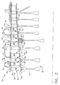
- FIG. 2 is a cross-sectional illustration of a portion of a compressor 30 that may be used with gas turbine engine 10.
- Figure 3 illustrates an exemplary stator vane doublet 80.
- compressor 30 is a high pressure compressor.
- Compressor 30 includes a rotor assembly 32 and a stator assembly 34 that are positioned within a casing 36 that defines a flowpath 38.
- the rotor assembly 32 defines an inner flowpath boundary 40 of the flowpath 38.
- Stator assembly 34 defines an outer flowpath boundary 42 of flowpath 38.
- Compressor 30 includes a plurality of stages with each stage including a row of circumferentially-spaced rotor blades 50 and a row of stator vane assemblies 52.
- rotor blades 50 are coupled to a rotor disk 54. Specifically, each rotor blade 50 extends radially outwardly from rotor disk 54 and includes an airfoil 56 that extends radially from an inner blade platform 58 to a blade tip 60.
- Stator assembly 34 includes a plurality of rows of stator vane assemblies 52 with each row of vane assemblies 52 positioned between adjacent rows of rotor blades 50.
- the compressor stages are configured for cooperating with a motive or working fluid, such as air, such that the motive fluid is compressed in succeeding stages.
- Each row of vane assemblies 52 includes a plurality of circumferentially-spaced stator vanes 66 that each extends radially inward from casing 36 and includes an airfoil 68 that extends from an outer vane platform 70 to a vane tip 72.
- Airfoil 68 includes a leading edge 73 and a trailing edge 74.
- stator vanes 66 have no inner platform.
- Compressor 30 includes one stator vane row per stage, some of which are bleed stages 76.
- vane assembly 52 includes a plurality of circumferentially-spaced stator vane doublets 80.
- stator vane doublet 80 includes a pair of stator vanes 66 joined at abutting edges 82 of their respective outer stator vane platforms 70 to form a vane segment.
- the joined platforms 70 are configured to be received in a vane rail 88 formed in compressor casing 36 as will be described.
- the stator vane doublet 80 includes two airfoils 68 joined together through a brazing process and has a cicrunferential width W.
- stator vanes 66 are joined by a gold-nickel braze material.
- Each stator vane platform 70 includes an inwardly facing surface 84 that defines a portion of outer flowpath boundary 42 in compressor 30.
- stator vane doublet 80 includes a bleed hole 86 formed in the joined vane platforms 70 between airfoils 68. Bleed holes 86 bleed off a portion of the motive fluid for use in cooling one or more stages of HP turbine 18.
- Figure 4 illustrates a cross sectional view of stator vane doublet 80 mounted within casing 36.
- Casing 36 includes casing vane rails 88 that each includes a vane platform engagement surface 90.
- Stator vane platform 70 includes dovetails 92 that are received in casing vane rails 88.
- a vane rail liner 94 is mounted within casing vane rails 88 and stator vane doublets 80 are received within vane rail liner 94.
- Vane rail liner 94 provides a sacrificial wear surface between casing vane rails 88 and stator vane platform dovetails 92.
- stator vane doublet 80 provides a vane segment that has a circumferential width W that is sufficiently large to substantially reduce a range of relative movement between stator vane platforms 70 of stator vanes 66 and casing vane rails 88.
- the reduced allowable movement reduces an amount of wear experienced between casing vane rails 88 and stator vane platforms 70.
- vane rail liner 94 and stator vane doublet 80 cooperate to further reduce the range of relative movement between stator vane doublet 80 and casing vane rail 88. Vibration from the coupled stator vane airfoils 68 partially cancel each other so that with stator vane doublet 80, vibration transmitted to joined platforms 70 is reduced.
- Stator vanes 66 are joined to form vane doublets 80.
- abutting edges 82 of stator vane platforms 70 of stator vanes 66 are first nickel-plated.
- the stator vanes 66 are then mounted in a precision tack welding fixture (not shown) that has a curvature substantially corresponding to a curvature of casing vane rail 88 and tack welded.
- the tack welded stator vanes 66 are then placed in a carbon member (not shown) to hold the desired shape during the braze furnace cycle.
- the tack welded stator vanes 66 are then brazed along outer vane platforms 70 using a gold-nickel braze alloy to form stator vane doublet 80.
- the gold-nickel braze provides ductility and temperature stability in the braze joint necessary for durability of the joint during engine operation. After brazing, the stator vane doublet 80 is re-aged in the carbon member to restore metallurgical properties.
- Assembly of vane doublet 80 into compressor casing 36 is accomplished by mounting a casing vane rail liner 94 on casing vane rail 88 and mounting vane doublet 80 within vane rail liner 94.
- the extended platform length of vane doublet 80 together with casing vane rail liner 88 take up excess clearance in casing vane rail 88 which facilitates reducing a vibration response of vane doublet 80 with respect to individual vanes 66.
- the above described compressor assembly provides a cost effective and reliable means for reducing stator vane platform to casing vane rail wear. More specifically, the compressor assembly employs stator vane doublets at the compressor bleed stages.
- the stator vane doublets provide vane segment that have a circumferential width that is sufficiently large to substantially reduce the amount of allowable movement between stator vane platforms and the casing vane rails. The reduced allowable movement reduces the amount of wear experienced between the casing vane rails and the stator vane platforms.
- a vane rail liner further reduces movement between the stator vane doublet and casing vane rail and provides a sacrificial surface which can be easily replaced. Vibration from the coupled stator vane airfoils also partially cancels each other so that with the stator vane doublet, vibration transmitted to the joined platforms is reduced.
Applications Claiming Priority (1)
| Application Number | Priority Date | Filing Date | Title |
|---|---|---|---|
| US10/982,050 US7278821B1 (en) | 2004-11-04 | 2004-11-04 | Methods and apparatus for assembling gas turbine engines |
Publications (3)
| Publication Number | Publication Date |
|---|---|
| EP1657405A2 true EP1657405A2 (fr) | 2006-05-17 |
| EP1657405A3 EP1657405A3 (fr) | 2010-06-23 |
| EP1657405B1 EP1657405B1 (fr) | 2011-09-21 |
Family
ID=35708495
Family Applications (1)
| Application Number | Title | Priority Date | Filing Date |
|---|---|---|---|
| EP05256666A Expired - Fee Related EP1657405B1 (fr) | 2004-11-04 | 2005-10-27 | Assemblage d'aubes directrices de turbine à gaz |
Country Status (4)
| Country | Link |
|---|---|
| US (1) | US7278821B1 (fr) |
| EP (1) | EP1657405B1 (fr) |
| JP (1) | JP4974101B2 (fr) |
| CN (1) | CN1769648A (fr) |
Cited By (4)
| Publication number | Priority date | Publication date | Assignee | Title |
|---|---|---|---|---|
| FR2938872A1 (fr) * | 2008-11-26 | 2010-05-28 | Snecma | Dispositif anti-usure pour aubes d'un distributeur de turbine d'une turbomachine aeronautique |
| EP2811121A1 (fr) * | 2013-06-03 | 2014-12-10 | Techspace Aero S.A. | Carter composite de compresseur de turbomachine axiale avec bride de fixation métallique |
| EP2890872A4 (fr) * | 2012-08-28 | 2016-07-20 | United Technologies Corp | Ensemble de groupements d'aubes à singlet |
| EP2612998A3 (fr) * | 2012-01-05 | 2017-07-12 | United Technologies Corporation | Garniture de fixation intégrée d'aube de stator et ressort amortisseur |
Families Citing this family (22)
| Publication number | Priority date | Publication date | Assignee | Title |
|---|---|---|---|---|
| US20100303608A1 (en) * | 2006-09-28 | 2010-12-02 | Mitsubishi Heavy Industries, Ltd. | Two-shaft gas turbine |
| US7686576B2 (en) * | 2006-10-24 | 2010-03-30 | General Electric Company | Method and apparatus for assembling gas turbine engines |
| US7806655B2 (en) * | 2007-02-27 | 2010-10-05 | General Electric Company | Method and apparatus for assembling blade shims |
| US7854583B2 (en) * | 2007-08-08 | 2010-12-21 | Genral Electric Company | Stator joining strip and method of linking adjacent stators |
| US20100054929A1 (en) * | 2008-09-04 | 2010-03-04 | General Electric Company | Turbine airfoil clocking |
| US20100166550A1 (en) * | 2008-12-31 | 2010-07-01 | Devangada Siddaraja M | Methods, systems and/or apparatus relating to frequency-tuned turbine blades |
| EP2308628A1 (fr) * | 2009-10-06 | 2011-04-13 | Siemens Aktiengesellschaft | Méthode d'enlévement d'un composant brasé avec chauffage local du lieu de brasage |
| US8920112B2 (en) | 2012-01-05 | 2014-12-30 | United Technologies Corporation | Stator vane spring damper |
| US10309235B2 (en) * | 2012-08-27 | 2019-06-04 | United Technologies Corporation | Shiplap cantilevered stator |
| US9334756B2 (en) | 2012-09-28 | 2016-05-10 | United Technologies Corporation | Liner and method of assembly |
| US9796055B2 (en) * | 2013-02-17 | 2017-10-24 | United Technologies Corporation | Turbine case retention hook with insert |
| US20150362463A1 (en) | 2013-03-01 | 2015-12-17 | Kyocera Corporation | Sensor |
| JP6185783B2 (ja) * | 2013-07-29 | 2017-08-23 | 三菱日立パワーシステムズ株式会社 | 軸流圧縮機、軸流圧縮機を備えたガスタービンおよび軸流圧縮機の改造方法 |
| GB201400756D0 (en) * | 2014-01-16 | 2014-03-05 | Rolls Royce Plc | Blisk |
| US20160333890A1 (en) * | 2014-01-24 | 2016-11-17 | United Technologies Corporation | Gas turbine engine inner case with non-integral vanes |
| US11339673B2 (en) | 2020-01-17 | 2022-05-24 | Raytheon Technologies Corporation | Rotor assembly with internal vanes |
| US11208892B2 (en) | 2020-01-17 | 2021-12-28 | Raytheon Technologies Corporation | Rotor assembly with multiple rotor disks |
| US11434771B2 (en) | 2020-01-17 | 2022-09-06 | Raytheon Technologies Corporation | Rotor blade pair for rotational equipment |
| US11286781B2 (en) | 2020-01-17 | 2022-03-29 | Raytheon Technologies Corporation | Multi-disk bladed rotor assembly for rotational equipment |
| US11371351B2 (en) | 2020-01-17 | 2022-06-28 | Raytheon Technologies Corporation | Multi-disk bladed rotor assembly for rotational equipment |
| US11401814B2 (en) | 2020-01-17 | 2022-08-02 | Raytheon Technologies Corporation | Rotor assembly with internal vanes |
| US11952917B2 (en) * | 2022-08-05 | 2024-04-09 | Rtx Corporation | Vane multiplet with conjoined singlet vanes |
Citations (4)
| Publication number | Priority date | Publication date | Assignee | Title |
|---|---|---|---|---|
| US4155680A (en) * | 1977-02-14 | 1979-05-22 | General Electric Company | Compressor protection means |
| US5846050A (en) * | 1997-07-14 | 1998-12-08 | General Electric Company | Vane sector spring |
| EP1104836A2 (fr) * | 1999-12-03 | 2001-06-06 | General Electric Company | Resort de serrage pour secteurs des aubes de guidage et méthode de fixation |
| US20030057263A1 (en) * | 2000-04-28 | 2003-03-27 | Beedon Kent W. | Method of brazing and article made therefrom |
Family Cites Families (12)
| Publication number | Priority date | Publication date | Assignee | Title |
|---|---|---|---|---|
| US2945290A (en) * | 1957-09-16 | 1960-07-19 | Gen Electric | Stator vane half ring assemblies |
| GB929960A (en) * | 1960-05-09 | 1963-06-26 | Werkspoor Nv | A turbine nozzle-ring assembly with guide blades and method for assembling the same |
| US4270256A (en) * | 1979-06-06 | 1981-06-02 | General Motors Corporation | Manufacture of composite turbine rotors |
| GB2249356B (en) * | 1990-11-01 | 1995-01-18 | Rolls Royce Plc | Shroud liners |
| US5182855A (en) * | 1990-12-13 | 1993-02-02 | General Electric Company | Turbine nozzle manufacturing method |
| US5188507A (en) * | 1991-11-27 | 1993-02-23 | General Electric Company | Low-pressure turbine shroud |
| US5333995A (en) * | 1993-08-09 | 1994-08-02 | General Electric Company | Wear shim for a turbine engine |
| GB9815611D0 (en) * | 1998-07-18 | 1998-09-16 | Rolls Royce Plc | Improvements in or relating to turbine cooling |
| US6290466B1 (en) * | 1999-09-17 | 2001-09-18 | General Electric Company | Composite blade root attachment |
| US6609880B2 (en) | 2001-11-15 | 2003-08-26 | General Electric Company | Methods and apparatus for cooling gas turbine nozzles |
| US6729842B2 (en) | 2002-08-28 | 2004-05-04 | General Electric Company | Methods and apparatus to reduce seal rubbing within gas turbine engines |
| US6808364B2 (en) | 2002-12-17 | 2004-10-26 | General Electric Company | Methods and apparatus for sealing gas turbine engine variable vane assemblies |
-
2004
- 2004-11-04 US US10/982,050 patent/US7278821B1/en active Active
-
2005
- 2005-10-21 JP JP2005306552A patent/JP4974101B2/ja not_active Expired - Fee Related
- 2005-10-27 EP EP05256666A patent/EP1657405B1/fr not_active Expired - Fee Related
- 2005-11-04 CN CNA2005101188038A patent/CN1769648A/zh active Pending
Patent Citations (4)
| Publication number | Priority date | Publication date | Assignee | Title |
|---|---|---|---|---|
| US4155680A (en) * | 1977-02-14 | 1979-05-22 | General Electric Company | Compressor protection means |
| US5846050A (en) * | 1997-07-14 | 1998-12-08 | General Electric Company | Vane sector spring |
| EP1104836A2 (fr) * | 1999-12-03 | 2001-06-06 | General Electric Company | Resort de serrage pour secteurs des aubes de guidage et méthode de fixation |
| US20030057263A1 (en) * | 2000-04-28 | 2003-03-27 | Beedon Kent W. | Method of brazing and article made therefrom |
Cited By (9)
| Publication number | Priority date | Publication date | Assignee | Title |
|---|---|---|---|---|
| FR2938872A1 (fr) * | 2008-11-26 | 2010-05-28 | Snecma | Dispositif anti-usure pour aubes d'un distributeur de turbine d'une turbomachine aeronautique |
| WO2010060938A1 (fr) * | 2008-11-26 | 2010-06-03 | Snecma | Dispositif anti-usure pour aubes d'un distributeur de turbine d'une turbomachine aeronautique |
| CN102227546A (zh) * | 2008-11-26 | 2011-10-26 | 斯奈克玛 | 用于航空涡轮引擎的涡轮分布器的叶片的耐磨装置 |
| US9062553B2 (en) | 2008-11-26 | 2015-06-23 | Snecma | Anti-wear device for the blades of a turbine distributor in an aeronautical turbine engine |
| EP2612998A3 (fr) * | 2012-01-05 | 2017-07-12 | United Technologies Corporation | Garniture de fixation intégrée d'aube de stator et ressort amortisseur |
| EP2890872A4 (fr) * | 2012-08-28 | 2016-07-20 | United Technologies Corp | Ensemble de groupements d'aubes à singlet |
| US9650905B2 (en) | 2012-08-28 | 2017-05-16 | United Technologies Corporation | Singlet vane cluster assembly |
| EP2811121A1 (fr) * | 2013-06-03 | 2014-12-10 | Techspace Aero S.A. | Carter composite de compresseur de turbomachine axiale avec bride de fixation métallique |
| CN104213947A (zh) * | 2013-06-03 | 2014-12-17 | 航空技术空间股份有限公司 | 具有用于轴流式涡轮机压缩机的金属固定凸缘的复合壳体 |
Also Published As
| Publication number | Publication date |
|---|---|
| EP1657405B1 (fr) | 2011-09-21 |
| US7278821B1 (en) | 2007-10-09 |
| JP2006132532A (ja) | 2006-05-25 |
| EP1657405A3 (fr) | 2010-06-23 |
| JP4974101B2 (ja) | 2012-07-11 |
| CN1769648A (zh) | 2006-05-10 |
Similar Documents
| Publication | Publication Date | Title |
|---|---|---|
| EP1657405B1 (fr) | Assemblage d'aubes directrices de turbine à gaz | |
| US7984547B2 (en) | Method for manufacturing and/or repairing components for gas turbines | |
| US8296945B2 (en) | Method for repairing a turbine nozzle segment | |
| AU2007214378B2 (en) | Methods and apparatus for fabricating turbine engines | |
| JP6692609B2 (ja) | タービンバケット組立体及びタービンシステム | |
| US8257028B2 (en) | Turbine nozzle segment | |
| EP1992786A2 (fr) | Plateforme pour aube rotorique et ensemble rotor aubagé associé | |
| US20070163114A1 (en) | Methods for fabricating components | |
| JP2016505103A (ja) | ハイブリッドタービンノズル | |
| EP1686242A2 (fr) | Méthode et appareil pour maintenir le jeu des extrémités des aubes d'un rotor de turbine | |
| US20150345307A1 (en) | Turbine bucket assembly and turbine system | |
| US8177502B2 (en) | Vane with reduced stress | |
| US9694440B2 (en) | Support collar geometry for linear friction welding | |
| US8235652B2 (en) | Turbine nozzle segment | |
| US20150345309A1 (en) | Turbine bucket assembly and turbine system | |
| JP2005201242A (ja) | ガスタービンロータブレードを修理する方法 | |
| EP3225794A1 (fr) | Ensemble de carénage de moteur à turbine | |
| CN112805453A (zh) | 涡轮机叶片末端附件 | |
| EP2189662A2 (fr) | Aube de turbine à contraintes réduites | |
| CN112523820A (zh) | 涡轮发动机组件 | |
| US20100126018A1 (en) | Method of manufacturing a vane with reduced stress | |
| EP2952682A1 (fr) | Aube pour moteur à turbine à gaz avec une plate-forme refroidie | |
| EP3578759B1 (fr) | Profil aérodynamique et procédé associé pour diriger un flux de refroidissement | |
| CN112912595A (zh) | 翼面试样块附接 | |
| US10316673B2 (en) | CMC turbine blade platform damper |
Legal Events
| Date | Code | Title | Description |
|---|---|---|---|
| PUAI | Public reference made under article 153(3) epc to a published international application that has entered the european phase |
Free format text: ORIGINAL CODE: 0009012 |
|
| AK | Designated contracting states |
Kind code of ref document: A2 Designated state(s): AT BE BG CH CY CZ DE DK EE ES FI FR GB GR HU IE IS IT LI LT LU LV MC NL PL PT RO SE SI SK TR |
|
| AX | Request for extension of the european patent |
Extension state: AL BA HR MK YU |
|
| PUAL | Search report despatched |
Free format text: ORIGINAL CODE: 0009013 |
|
| AK | Designated contracting states |
Kind code of ref document: A3 Designated state(s): AT BE BG CH CY CZ DE DK EE ES FI FR GB GR HU IE IS IT LI LT LU LV MC NL PL PT RO SE SI SK TR |
|
| AX | Request for extension of the european patent |
Extension state: AL BA HR MK YU |
|
| 17P | Request for examination filed |
Effective date: 20101223 |
|
| AKX | Designation fees paid |
Designated state(s): DE FR GB |
|
| GRAP | Despatch of communication of intention to grant a patent |
Free format text: ORIGINAL CODE: EPIDOSNIGR1 |
|
| RIC1 | Information provided on ipc code assigned before grant |
Ipc: F02C 3/06 20060101ALI20110228BHEP Ipc: F01D 9/04 20060101AFI20110228BHEP |
|
| RTI1 | Title (correction) |
Free format text: STATOR VANE ASSEMBLY FOR A GAS TURBINE |
|
| GRAS | Grant fee paid |
Free format text: ORIGINAL CODE: EPIDOSNIGR3 |
|
| GRAA | (expected) grant |
Free format text: ORIGINAL CODE: 0009210 |
|
| AK | Designated contracting states |
Kind code of ref document: B1 Designated state(s): DE FR GB |
|
| REG | Reference to a national code |
Ref country code: GB Ref legal event code: FG4D |
|
| REG | Reference to a national code |
Ref country code: DE Ref legal event code: R096 Ref document number: 602005030114 Country of ref document: DE Effective date: 20111124 |
|
| PLBE | No opposition filed within time limit |
Free format text: ORIGINAL CODE: 0009261 |
|
| STAA | Information on the status of an ep patent application or granted ep patent |
Free format text: STATUS: NO OPPOSITION FILED WITHIN TIME LIMIT |
|
| 26N | No opposition filed |
Effective date: 20120622 |
|
| REG | Reference to a national code |
Ref country code: DE Ref legal event code: R097 Ref document number: 602005030114 Country of ref document: DE Effective date: 20120622 |
|
| REG | Reference to a national code |
Ref country code: FR Ref legal event code: PLFP Year of fee payment: 11 |
|
| REG | Reference to a national code |
Ref country code: FR Ref legal event code: PLFP Year of fee payment: 12 |
|
| PGFP | Annual fee paid to national office [announced via postgrant information from national office to epo] |
Ref country code: GB Payment date: 20161027 Year of fee payment: 12 Ref country code: DE Payment date: 20161027 Year of fee payment: 12 Ref country code: FR Payment date: 20161025 Year of fee payment: 12 |
|
| REG | Reference to a national code |
Ref country code: DE Ref legal event code: R119 Ref document number: 602005030114 Country of ref document: DE |
|
| GBPC | Gb: european patent ceased through non-payment of renewal fee |
Effective date: 20171027 |
|
| REG | Reference to a national code |
Ref country code: FR Ref legal event code: ST Effective date: 20180629 |
|
| PG25 | Lapsed in a contracting state [announced via postgrant information from national office to epo] |
Ref country code: DE Free format text: LAPSE BECAUSE OF NON-PAYMENT OF DUE FEES Effective date: 20180501 Ref country code: GB Free format text: LAPSE BECAUSE OF NON-PAYMENT OF DUE FEES Effective date: 20171027 |
|
| PG25 | Lapsed in a contracting state [announced via postgrant information from national office to epo] |
Ref country code: FR Free format text: LAPSE BECAUSE OF NON-PAYMENT OF DUE FEES Effective date: 20171031 |