EP1656879B1 - Balloon controller for endoscopic apparatus - Google Patents
Balloon controller for endoscopic apparatus Download PDFInfo
- Publication number
- EP1656879B1 EP1656879B1 EP05023857.5A EP05023857A EP1656879B1 EP 1656879 B1 EP1656879 B1 EP 1656879B1 EP 05023857 A EP05023857 A EP 05023857A EP 1656879 B1 EP1656879 B1 EP 1656879B1
- Authority
- EP
- European Patent Office
- Prior art keywords
- balloon
- pressure
- sequencer
- air
- switch
- Prior art date
- Legal status (The legal status is an assumption and is not a legal conclusion. Google has not performed a legal analysis and makes no representation as to the accuracy of the status listed.)
- Active
Links
- 238000003780 insertion Methods 0.000 claims description 87
- 230000037431 insertion Effects 0.000 claims description 87
- 239000012530 fluid Substances 0.000 claims description 23
- 238000004891 communication Methods 0.000 claims description 5
- 230000002159 abnormal effect Effects 0.000 description 22
- 238000012545 processing Methods 0.000 description 20
- 210000001035 gastrointestinal tract Anatomy 0.000 description 18
- 230000005856 abnormality Effects 0.000 description 15
- 238000000034 method Methods 0.000 description 14
- 238000010586 diagram Methods 0.000 description 12
- XLYOFNOQVPJJNP-UHFFFAOYSA-N water Substances O XLYOFNOQVPJJNP-UHFFFAOYSA-N 0.000 description 12
- 230000003287 optical effect Effects 0.000 description 9
- 238000005286 illumination Methods 0.000 description 7
- 230000002093 peripheral effect Effects 0.000 description 7
- 238000001514 detection method Methods 0.000 description 6
- 230000007257 malfunction Effects 0.000 description 6
- 210000000813 small intestine Anatomy 0.000 description 6
- 238000010276 construction Methods 0.000 description 4
- 238000005452 bending Methods 0.000 description 3
- 238000002347 injection Methods 0.000 description 3
- 239000007924 injection Substances 0.000 description 3
- 210000002429 large intestine Anatomy 0.000 description 3
- 239000007788 liquid Substances 0.000 description 3
- 230000001681 protective effect Effects 0.000 description 3
- 244000145845 chattering Species 0.000 description 2
- 238000001816 cooling Methods 0.000 description 2
- 239000000314 lubricant Substances 0.000 description 2
- 230000005540 biological transmission Effects 0.000 description 1
- 210000001124 body fluid Anatomy 0.000 description 1
- 239000010839 body fluid Substances 0.000 description 1
- 230000003139 buffering effect Effects 0.000 description 1
- 238000006243 chemical reaction Methods 0.000 description 1
- 230000000994 depressogenic effect Effects 0.000 description 1
- 210000001198 duodenum Anatomy 0.000 description 1
- 230000000694 effects Effects 0.000 description 1
- 239000013013 elastic material Substances 0.000 description 1
- 238000009413 insulation Methods 0.000 description 1
- 230000003902 lesion Effects 0.000 description 1
- 238000005259 measurement Methods 0.000 description 1
- 238000012544 monitoring process Methods 0.000 description 1
- 238000013021 overheating Methods 0.000 description 1
- 230000002572 peristaltic effect Effects 0.000 description 1
- 238000003825 pressing Methods 0.000 description 1
- 238000010926 purge Methods 0.000 description 1
- 238000004804 winding Methods 0.000 description 1
Images


Classifications
-
- A—HUMAN NECESSITIES
- A61—MEDICAL OR VETERINARY SCIENCE; HYGIENE
- A61B—DIAGNOSIS; SURGERY; IDENTIFICATION
- A61B1/00—Instruments for performing medical examinations of the interior of cavities or tubes of the body by visual or photographical inspection, e.g. endoscopes; Illuminating arrangements therefor
- A61B1/005—Flexible endoscopes
- A61B1/01—Guiding arrangements therefore
-
- A—HUMAN NECESSITIES
- A61—MEDICAL OR VETERINARY SCIENCE; HYGIENE
- A61B—DIAGNOSIS; SURGERY; IDENTIFICATION
- A61B1/00—Instruments for performing medical examinations of the interior of cavities or tubes of the body by visual or photographical inspection, e.g. endoscopes; Illuminating arrangements therefor
- A61B1/00002—Operational features of endoscopes
- A61B1/00039—Operational features of endoscopes provided with input arrangements for the user
- A61B1/00042—Operational features of endoscopes provided with input arrangements for the user for mechanical operation
-
- A—HUMAN NECESSITIES
- A61—MEDICAL OR VETERINARY SCIENCE; HYGIENE
- A61B—DIAGNOSIS; SURGERY; IDENTIFICATION
- A61B1/00—Instruments for performing medical examinations of the interior of cavities or tubes of the body by visual or photographical inspection, e.g. endoscopes; Illuminating arrangements therefor
- A61B1/00064—Constructional details of the endoscope body
- A61B1/00071—Insertion part of the endoscope body
- A61B1/0008—Insertion part of the endoscope body characterised by distal tip features
- A61B1/00082—Balloons
-
- A—HUMAN NECESSITIES
- A61—MEDICAL OR VETERINARY SCIENCE; HYGIENE
- A61B—DIAGNOSIS; SURGERY; IDENTIFICATION
- A61B1/00—Instruments for performing medical examinations of the interior of cavities or tubes of the body by visual or photographical inspection, e.g. endoscopes; Illuminating arrangements therefor
- A61B1/00147—Holding or positioning arrangements
- A61B1/00154—Holding or positioning arrangements using guiding arrangements for insertion
-
- A—HUMAN NECESSITIES
- A61—MEDICAL OR VETERINARY SCIENCE; HYGIENE
- A61B—DIAGNOSIS; SURGERY; IDENTIFICATION
- A61B1/00—Instruments for performing medical examinations of the interior of cavities or tubes of the body by visual or photographical inspection, e.g. endoscopes; Illuminating arrangements therefor
- A61B1/12—Instruments for performing medical examinations of the interior of cavities or tubes of the body by visual or photographical inspection, e.g. endoscopes; Illuminating arrangements therefor with cooling or rinsing arrangements
-
- A—HUMAN NECESSITIES
- A61—MEDICAL OR VETERINARY SCIENCE; HYGIENE
- A61B—DIAGNOSIS; SURGERY; IDENTIFICATION
- A61B1/00—Instruments for performing medical examinations of the interior of cavities or tubes of the body by visual or photographical inspection, e.g. endoscopes; Illuminating arrangements therefor
- A61B1/31—Instruments for performing medical examinations of the interior of cavities or tubes of the body by visual or photographical inspection, e.g. endoscopes; Illuminating arrangements therefor for the rectum, e.g. proctoscopes, sigmoidoscopes, colonoscopes
-
- A—HUMAN NECESSITIES
- A61—MEDICAL OR VETERINARY SCIENCE; HYGIENE
- A61B—DIAGNOSIS; SURGERY; IDENTIFICATION
- A61B1/00—Instruments for performing medical examinations of the interior of cavities or tubes of the body by visual or photographical inspection, e.g. endoscopes; Illuminating arrangements therefor
- A61B1/00002—Operational features of endoscopes
- A61B1/00043—Operational features of endoscopes provided with output arrangements
- A61B1/00045—Display arrangement
- A61B1/0005—Display arrangement combining images e.g. side-by-side, superimposed or tiled
Definitions
- the present invention relates to a balloon controller for an endoscopic apparatus according to the preamble of claim 1; and, more particularly, to a balloon controller for controlling a balloon used in an endoscopic apparatus for observing a deep-part digestive tract such as the small intestine or the large intestine.
- an insertion portion of an endoscope When an insertion portion of an endoscope is inserted into a deep-part digestive tract such as the small intestine, a force for insertion cannot be easily transmitted to the foremost end of the insertion portion due to the existence of complicated bends in the intestinal tract and it is difficult to insert the insertion portion to a deep part, if the insertion portion is simply forced into the tract. For example, if an unnecessary bend or warp is caused in the insertion portion, the insertion portion cannot be inserted to a deeper portion of the tract.
- a method has therefore been proposed in which the insertion portion of an endoscope is inserted into a body cavity together with an insertion assist implement which caps the insertion portion, and an unnecessary bend or warp in the insertion portion is prevented by guiding the insertion portion with the insertion assist implement.
- Japanese Patent Application Laid-Open No. 2002-301019 discloses an endoscopic apparatus in which a first balloon is provided on an insertion portion of an endoscope close to the foremost end of the insertion portion and a second balloon is provided on an insertion assist implement (also referred to as an over tube or sliding tube) close to the foremost end of the insertion assist implement.
- the first and second balloons can fix the insertion portion and the insertion assist implement in the intestinal tract such as the small intestine by expanding the first and second balloons.
- This endoscopic apparatus is capable of inserting the insertion portion to a deep portion of an intestinal tract such as the small intestine having complicated bends by alternately inserting the insertion portion and the insertion assist implement while repeating expanding and shrinking the first and second balloons.
- the pressure in each balloon is measured with a pressure sensor and the balloon is expanded according to the measured pressure value. Therefore, the pressure in the expanded balloon can be controlled at a predetermined set pressure to reliably retain an intestinal tract.
- US 2003/083547 A1 discloses a balloon controller in which a valve member as a leakage device is provided in tube parts for communication between the balloons and fluid supply and the drawing device.
- the valve member is embodied as a pressure relief device.
- Such pressure relief device is a valve member which opens under a certain pressure.
- US 4,993,351 A discloses a balloon catheter device having port means for purging air from the catheter.
- US 4,856,510 A discloses a tracheal tube inflator.
- This device includes serially arranged pilot and control balloons. Connected to the pilot balloon is a check valve biased into the closed position.
- the control balloon comprises means for moving the check valve into the opened position.
- an object of the present invention is to provide a balloon controller for an endoscopic apparatus capable of reliably preventing the occurrence of an abnormal pressure in a balloon to improve safety.
- a balloon controller for an endoscope apparatus having the features of claim 1.
- a leakage device is provided in tube paths for communication between the balloons and the fluid supply and drawing device. Therefore the fluid can be leaked by use of the fluid supply and drawing device and other components before an abnormal pressure is reached, thereby preventing generation of an abnormal pressure in each balloon.
- the leakage device in the balloon controller comprises a fixed throttle member. According to that aspect, an improvement in terms of safety can be achieved by allowing leakage of the fluid at all times, and the effect of buffering variation in the pressure in each balloon.
- the leakage device controls the pressure in each balloon by leaking the fluid so that the pressure is 13.5 kPa or less. If the pressure is set in such a range, imposition of strain on a patient can be reliably prevented.
- the leakage device is provided in the tube paths for communication between the pumps and balloons, and the fluid can be leaked before an abnormal pressure is generated due to a malfunction of the pumps for example, thereby preventing generation of the abnormal pressure in the balloons.
- Fig. 1 is a diagram showing a system configuration representing an implementation of an endoscopic apparatus to which a balloon controller in accordance with the present invention is applied.
- the endoscopic apparatus is constituted mainly by an endoscope 10, an insertion assist implement 70 and a balloon controller 100.
- the endoscope 10 has an at-hand operating portion 14 and an insertion portion 12 which is joined to the at-hand operating portion 14, and which is inserted into a body cavity.
- One end of a universal cable 16 is connected to the at-hand operating portion 14, and an LG connector 18 is provided at the other end of the universal cable 16.
- the LG connector 18 is detachably attached to a light source unit 20 to enable transmission of illumination light to an illumination optical system 54 (see Fig. 2 ) described below.
- An electric connector 24 is connected to the LG connector 18 via a cable 22 and is detachably attached to a processor 26.
- an air/water supply button 28 On the at-hand operating portion 14, an air/water supply button 28, an aspiration button 30, a shutter button 32 and a function change button 34 are provided one adjacent to another and a pair of angle knobs 36 are provided.
- a balloon air supply port 38 is formed at a base end of the at-hand operating portion 14 by a tube bent into L shape. A fluid such as air is supplied to or drawn from the balloon air supply port 38 to expand or shrink a first balloon 60 described below.
- the insertion portion 12 includes a soft portion 40, a bending portion 42 and a foremost end portion 44 provided in this order from the at-hand operating portion 14 side.
- the bending portion 42 is remotely operated by rotating the angle knobs 36 on the at-hand operating portion 14 so that the bending portion 42 bends. In this way, the foremost end portion 44 can be directed as desired.
- an observation optical system 52 As shown in Fig. 2 , an observation optical system 52, illumination optical systems 54, an air/water supply nozzle 56 and a forceps opening 58 are provided in a foremost end surface 45 of the foremost end portion 44.
- a charge-coupled device (CCD) (not shown) is provided at the rear of the observation optical system 52, and a signal cable (not shown) is connected to a base plate on which the CCD is supported.
- the signal cable is extended to the electric connector 24 by being passed through the insertion portion 12, the at-hand operating portion 14, the universal cable 16 and other components shown in Fig. 1 to be connected to the processor 26.
- An observed image taken through the observation optical system 52 is imaged on the light receiving surface of the CCD to be converted into an electrical signal. This electrical signal is output to the processor 26 via the signal cable to be converted into a video signal, thus enabling the observed image to be displayed on a monitor 50 connected to the processor 26.
- a light guide (not shown) is provided at the rear of the illumination optical systems 54 shown in Fig. 2 .
- This light guide is passed through the insertion portion 12, the at-hand operating portion 14 and the universal cable 16 shown in Fig. 1 and has its incidence end placed in the LG connector 18.
- the LG connector 18 is connected to a light source unit 20 to enable illumination light emitted from the light source unit 20 to be transmitted to the illumination optical systems 54 through the light guide and radiated forward from the illumination optical systems 54.
- the air/water supply nozzle 56 shown in Fig. 2 communicates with a valve (not shown) operated with the air/water supply button 28 shown in Fig. 1 .
- This valve communicates with an air/water supply connector 48 provided in the LG connector 18.
- An air/water supply device (not shown) is connected to the air/water supply connector 48 to supply air or water. Air or water can be jetted from the air/water supply nozzle 56 toward the observation optical system 52 by operating the air/water supply button 28.
- the forceps opening 58 shown in Fig. 2 communicates with a forceps insertion portion 46 shown in Fig. 1 .
- An implement for a treatment such as forceps can be inserted through the forceps insertion portion 46 and guided to the forceps opening 58 to project from the same.
- the forceps opening 58 also communicates with a valve (not shown) operated with the aspiration button 30. This valve is connected to an aspiration connector 49 in the LG connector 18.
- An aspiration device (not shown) can be connected to the aspiration connector 49 to suck a lesion portion or the like through the forceps opening 58 by operating the valve by use of the aspiration button 30.
- the first balloon 60 made of an elastic material such as rubber is fitted around the outer peripheral surface of the insertion portion 12.
- the first balloon 60 is formed into a generally cylindrical shape constricted at its opposite ends.
- the insertion portion 12 is passed through the first balloon 60 and the first balloon 60 is placed in a desired position on the insertion portion 12.
- fixing rings 62 made of rubber are fitted around opposite end portions of the first balloon 60, as shown in Fig. 2 , thus fixing the first balloon 60 on the insertion portion 12.
- An air hole 64 is formed in the outer peripheral surface of the insertion portion 12 at a position corresponding to the attached position of the first balloon 60.
- the air hole 64 communicates with the balloon air supply port 38 provided in the at-hand operating portion 14 shown in Fig. 1 .
- the balloon air supply port 38 is connected to the balloon controller 100 via a tube 110 described below.
- the first balloon 60 can be expanded or shrunk by the balloon controller 100 supplying or drawing air. When air is supplied to the first balloon 60, the first balloon 60 expands so as to be generally spherical. When air is drawn, the first balloon 60 adheres to the outer surface of the insertion portion 12.
- the insertion assist implement 70 shown in Fig. 1 is formed into a cylindrical shape, has an inside diameter slightly larger than the outside diameter of the insertion portion 12, and has sufficiently high flexibility.
- the insertion assist implement 70 has a hard hold portion 72 at its base end.
- the insertion portion 12 is inserted into the insertion assist implement 70 through the hold portion 72.
- a second balloon 80 is attached to the insertion assist implement 70 in the vicinity of the foremost end of the insertion assist implement 70.
- the second balloon 80 is formed into a generally cylindrical shape constricted at its opposite ends.
- the second balloon 80 is attached to the insertion assist implement 70 passed through the second balloon 80 and is fixed on the insertion assist implement 70 by winding a string (not shown).
- a tube 74 attached to the outer peripheral surface of the insertion assist implement 70 communicates with the second balloon 80.
- a connector 76 is provided on an end portion of the tube 74, and a tube 120 is connected to the connector 76.
- the tube 120 is connected to the balloon controller 100.
- the balloon controller 100 supplies or draws air through the tube 120 to expand or shrink the second balloon 80.
- the second balloon 80 expends so as to be generally spherical.
- the second balloon 80 adheres to the outer peripheral surface of the insertion assist implement 70.
- An injection port 78 is provided at the base end of the insertion assist implement 70.
- the injection port 78 communicates with an opening (not shown) formed in an inner peripheral surface of the insertion assist implement 70.
- a lubricant e.g., water
- the lubricant can reduce friction between the inner peripheral surface of the insertion assist implement 70 and the outer peripheral surface of the insertion portion 12 when the insertion portion 12 is inserted in the insertion assist implement 70 to enable the insertion portion 12 and the insertion assist implement 70 to smoothly move relative to each other.
- the balloon controller 100 supplies a fluid such as air to the first balloon 60 or draws the fluid from the first balloon 60 and also supplies a fluid such as air to the second balloon 80 or draws the fluid from the first balloon 80.
- the balloon controller 100 is constituted mainly by a main unit 102 and a hand switch 104 for remote control.
- a power supply switch SW1, a stop switch SW2, a first pressure indicating portion 106, a second pressure indicating portion 108, a first function stop switch SW3 and a second function stop switch SW4 are provided in a front surface of the main unit 102.
- the first pressure indicating portion 106 and the second pressure indicating portion 108 are panels on which the values of pressures in the first balloon 60 and the second balloon 80 are respectively indicated.
- An error code is displayed on the pressure indicating portion 106 or 108 when an abnormality such as a break in the corresponding balloon occurs.
- the first function stop switch SW3 and the second function stop switch SW4 are switches by which an endoscope control system A and an insertion assist implement control system B described below are respectively turned on or off to function or stop functioning.
- the function stop switch SW3 or SW4 corresponding to the balloon not used is operated to stop functioning.
- the control system A or B stopped from functioning supply or drawing of air is completely stopped and the pressure indicating portion 106 or 108 is also off.
- Both the function stop switches SW3 and SW4 may be turned off to enable initialization or the like. For example, calibration with respect to ambient pressure is performed by turning off both the function stop switches SW3 and SW4 and by pressing all switches SW5 to SW9 in the hand switch 104.
- the tube 110 for supply of air to the first balloon 60 and for drawing of air from the first balloon 60 and the tube 120 for supply of air to the second balloon 80 and for drawing of air from the second balloon 80 are connected.
- the tubes 110 and 120 are connected to the main unit 102 through connection portions including back-flow preventing units 112 and 122 each for preventing a backward flow of a body fluid when the first or second balloon 60 or 80 is broken.
- Each of the back-flow preventing units 112 and 122 is constructed by incorporating a gas/liquid disengagement filter in a case in the form of a hollow disk detachably attached to the main unit 102 to prevent the fluid from flowing into the main unit 102 by the filter.
- the pressure indicating portions 106 and 108, the function stop switches SW3 and SW4 and back-flow preventing units 112 and 122 are disposed in a fixed configuration. That is, the pressure indicating portion 106, the function stop switch SW3 and the back-flow preventing unit 112 for the endoscope 10 are disposed on the right-hand side of the pressure indicating portion 108, the function stop switch SW4 and the back-flow preventing unit 122 for the insertion assist implement 70 respectively.
- the switch SW5 provided in the hand switch 104 is a stop switch similar to the stop switch SW2 on the main unit 102 side.
- the switch SW6 in the hand switch 104 is an on/off switch by which a command to pressurize or depressurize the first balloon 60 is input.
- the switch SW7 in the hand switch 104 is a pause switch for maintaining the pressure in the first balloon 60.
- the switch SW8 in the hand switch 104 is an on/off switch by which a command to pressurize or depressurize the second balloon 80 is input.
- the switch SW9 in the hand switch 104 is a pause switch for maintaining the pressure in the second balloon 80.
- the hand switch 104 is electrically connected to the main unit 102 via a cable 130.
- the hand switch 104 has a display portion (not shown in Fig. 1 ) on which the conditions of supply air to the first and second balloons 60 and 80 or the conditions of exhaust of air from the first and second balloons 60 and 80 are displayed.
- the balloon controller 100 arranged as described above expands each of the balloons 60 and 80 by supplying air to the balloon 60 or 80, and maintains the balloon 60 or 80 in the expanded state by controlling the air pressure in the balloon at a certain value. Also, the balloon controller 100 shrinks the balloons 60 or 80 by drawing air therefrom, and maintains the balloons 60 or 80 in the shrunken state by controlling the air pressure in the balloon at a certain value.
- the balloon controller 100 is connected to a balloon monitor 82 provided specially for monitoring of the balloons 60 and 80.
- the states of expansion/shrinkage of the balloons 60 and 80 are displayed on the balloon monitor 82.
- the values of pressures in the balloons 60 and 80 and the states of expansion/shrinkage of the balloons 60 and 80 may be displayed by being superimposed on an observed image obtained by the endoscope 10.
- the insertion portion 12 is first inserted into an intestinal tract (e.g., a descending part of the duodenum) 90, with the insertion assist implement 70 fitted around the insertion portion 12. At this time, the first and second balloons 60 and 80 are maintained in the shrunken state.
- an intestinal tract e.g., a descending part of the duodenum
- Air is thereafter supplied to the second balloon 80 to expand the second balloon 80 in a state where the foremost end of the insertion assist implement 70 is inserted to a bend in the intestinal tract 90, as shown in Fig. 4B . That is, the switch SW8 in the hand switch 104 is turned on to input a pressurization command, thereby supplying air from the balloon controller 100 to the second balloon 80 via the tube 120 so that second balloon 80 expands until an increased pressure set in advance is applied. The second balloon 80 is thereby caught in the intestinal tract 90 to fix the foremost end of the insertion assist implement 70 in the intestinal tract 90.
- the insertion assist implement 70 is drawn in, as shown in Fig. 4G .
- the intestinal tract 90 contracts and an unnecessary bend or warp in the insertion assist implement 70 is removed.
- Air is thereafter drawn from the first balloon 60 to shrink the first balloon 60, as shown in Fig. 4H . That is, the switch SW6 in the hand switch 104 is turned off to input a depressurization command, thereby drawing air from the first balloon 60 into the balloon controller 100 via the tube 110 so that the first balloon 60 shrinks until a reduced pressure set in advance is reached.
- the amount of insertion of the foremost end 44 of the insertion portion 12 in the intestinal tract 90 is increased as much as possible. That is, an insertion operation such as shown in Fig. 4C is again performed. The foremost end 44 of the insertion portion 12 is thereby inserted to a deeper portion of the intestinal tract 90.
- a fixing operation such as shown in Fig. 4D
- a forcing-in operation such as shown in Fig. 4E
- a catching operation such as shown in Fig. 4F
- a drawing-in operation such as shown in Fig. 4G
- an inserting operation such as shown in Fig. 4H
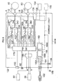
- Fig. 5 is a block diagram showing an example of implementation of the internal construction of the balloon controller 100.
- the main unit 102 of the balloon controller 100 is constituted mainly by a power supply circuit 160, a sequencer 170, the endoscope control system A and the insertion assist implement control system B.
- the power supply circuit 160 converts a commercial power input through a power plug 162 into dc power at a required voltage and supplies the dc power to each section in the main unit 102.
- the power supply circuit 160 is constituted by a fuse 164 and a switching power supply 166.
- the switching power supply 166 includes a power switch 166A, a primary power section 166B and a secondary power section 166C. Reinforced insulation is provided between the primary power section 166B and the secondary power section 166C.
- reference numeral 168 designates a potential equalization terminal
- reference numeral 169 denotes a protective grounding terminal.
- An intermediate circuit indicated by the double-dot-dash line is grounded in a protective grounding manner, and a casing indicated by the solid line is also grounded in a protective grounding manner.
- the sequencer 170 separately controls the endoscope control system A and the insertion assist implement control system B on the basis of various commands from the hand switch 104 and performs control operations to detect a pressure abnormality or the like, sound a buzzer BZ when detecting an abnormality.
- the sequencer 170 is connected to an image processing circuit 180, in which signals representing the values of measurement results obtained by a pressure sensors SA and SB undergo processing for conversion into image signals.
- the processed signals are sent to the balloon monitor 82 and the states of expansion/shrinkage of the balloons 60 and 80 are graphically displayed as images on the balloon monitor 82.
- the image processing circuit 180 is connected to the processor 26.
- an observed image signal obtained by the endoscope 10 is input through an input terminal a
- a superimposition signal is formed such that the states of expansion/shrinkage of the balloons 60 and 80 are superimposed on the observed image.
- the superimposition signal is output from an output terminal b to the processor 26, thereby enabling an image in which the states of the balloons are superimposed on the observed image to be displayed on the monitor 50 shown in Fig. 1 .
- the sequencer 170 is connected to a cooling fan 190 and a foot switch 192.
- the power supply switch SW1 see Fig. 3
- the cooling fan 190 is driven to blow air into the main unit 102 in order to prevent overheating.
- the foot switch 192 has a plurality of pedals, which are depressed by an operator to switch between supply of air and exhaust of air or to stop supply or exhaust of air. The operation of the sequencer 170 will be described below in detail.
- the endoscope control system A is constituted mainly by a pump PA1 for pressurization, a pump PA2 for depressurization, an electromagnetic valve VA1 for turning on/off supply of air from the pump PA1, an electromagnetic valve VA2 for turning on/off drawing of air with the pump PA2, an electromagnetic valve VA3 for switching between pressurization and depressurization, and the pressure sensor SA for detecting the pressure in the tube 110.
- Starting/stopping of the pressurizing pump PA1 and the depressurizing pump PA2 is controlled by the sequencer 170.
- Change of each of the three electromagnetic valves VA1, VA2, and VA3 is controlled by a drive signal from the sequencer 170.
- the pressure sensor SA is capable of detecting an increased pressure P 1 set in advance (e.g., a pressure higher than ambient pressure by 5.6 kPa), an abnormal pressure P 2 higher than the increased pressure P 1 (e.g., a pressure higher than ambient pressure by 8.2 kPa) and a reduced pressure P 3 set in advance (e.g., a pressure lower than ambient pressure by 6.0 kPa).
- the pressure detected by the pressure sensor SA is supplied to the sequencer 170 and indicated on the pressure indicating portion 106.
- a three-way value VA4 is provided between the pressurizing pump PA1 and the electromagnetic valve VA1, and a fixed throttle DA1 is mounted in the three-way value VA4. Part of air supplied from the pressurizing pump PA1 is released from the fixed throttle DA1 to atmospheric air at all times.
- a fixed throttle DA2 is provided between the electromagnetic valve VA3 and the gas/liquid disengagement unit 112. The rate of flow of a fluid in the tube 110 is controlled by the fixed throttle DA2.
- the insertion assist implement control system B has the same construction as that of the endoscope control system A.
- the insertion assist implement control system B is constituted mainly by a pump PB1 for pressurization, a pump PB2 for depressurization, an electromagnetic valve VB1 for turning on/off supply of air from the pump PB1, an electromagnetic valve VB2 for turning on/off drawing of air with the pump PB2, an electromagnetic valve VB3 for switching between pressurization and depressurization, and the pressure sensor SB for detecting the pressure in the tube 120.
- Starting/stopping of the pressurizing pump PB1 and the depressurizing pump PB2 is controlled by the sequencer 170.
- Change of each of the three electromagnetic valves VB1, VB2, and VB3 is controlled by a drive signal from the sequencer 170.
- the pressure sensor SB is capable of detecting the increased pressure P 1 set in advance (e.g., a pressure higher than ambient pressure by 5.6 kPa), the abnormal pressure P 2 higher than the increased pressure P 1 (e.g., a pressure higher than ambient pressure by 8.2 kPa) and the reduced pressure P 3 set in advance (e.g., a pressure lower than ambient pressure by 6.0 kPa).
- the pressure detected by the pressure sensor SB is supplied to the sequencer 170 and indicated on the pressure indicating portion 108.
- a three-way value VB4 is provided between the pressurizing pump PB1 and the electromagnetic valve VB1, and a fixed throttle DB 1 is mounted in the three-way value VB4. Part of air supplied from the pressurizing pump PB1 leaks from the fixed throttle DB 1 at all times.
- a fixed throttle DB2 is provided between the electromagnetic valve VB3 and the gas/liquid disengagement unit 122. The rate of flow of a fluid in the tube 120 is controlled by the fixed throttle DB2.
- sequencer 170 The operation of the sequencer 170 will be described in detail with reference to the flowcharts of Figs. 6 to 9 .
- the way in which endoscope balloon control is performed by the sequencer 170 and the way in which insertion assist implement balloon control is performed by the sequencer 170 are the same. Therefore, the description will be made only of the endoscope balloon control.
- Fig. 6 is a flowchart showing the outline of the operation of the sequencer 170.
- the sequencer 170 first determines whether or not a first balloon 60 depressurization command (i.e. a command input by turning off the switch SW6) has been input from the hand switch 104 (step S10). If the depressurization command has been input, the sequencer 170 executes depressurization processing shown in Fig. 7 .
- a first balloon 60 depressurization command i.e. a command input by turning off the switch SW6
- the sequencer 170 determines whether or not a first balloon 60 pressurization command (i.e. a command input by turning on the switch SW6) has been input from the hand switch 104 and whether or not a pause command to maintain the pressure in the balloon 60 (i.e., a command input by turning on the pause switch SW7) has been input from the hand switch 104 (steps S20 and S30). If the pressurization command has been input, the sequencer 170 executes pressurization processing shown in Fig. 8 . If the pause command has been input, the sequencer 170 executes pause processing shown in Fig. 9 .
- a green light emitting diode (LED) and a white LED are respectively provided in key tops of the switch SW6 and the pause switch SW7. Each of the green LED and the white LED is lighted when the switch is turned on. Also, a green LED and a white LED are respectively provided in the switch SW8 and the pause switch SW9.
- the sequencer 170 first resets time T in a timer for measuring time to 0 (step S102) and thereafter operates the control system A for depressurization (step S104). That is, the sequencer 170 turns off the electromagnetic valves VA1, VA2, and VA3 shown in Fig. 5 , and drives the pump PA2 for depressurization.
- the sequencer 170 determines from the detection signal from the pressure sensor SA whether or not the pressure in the tube 110 has reached the reduced pressure P 3 set in advance (step S106). If the pressure in the tube 110 has reached the reduced pressure P 3 , the sequencer 170 stops the depressurization operation (step S108).
- the depressurization operation is stopped by use of the electromagnetic valve VA2. Since the diameter of the air supply tube provided along the insertion portion 12 of the balloon-type endoscope 10 is sufficiently smaller than the diameter of the tube 110, the pressure in the tube 110 reaches the reduced pressure P 3 before the pressure in the first balloon 60 reaches the reduced pressure P 3 after the start of drawing of air (depressurization). The depressurization operation is thereby stopped. However, if the pressure in the first balloon 60 has not reached the reduced pressure P 3 , the pressure in the tube 110 is again increased to become higher than the reduced pressure P 3 . In this case, the sequencer 170 again starts the depressurization operation by referring to the detection signal from the pressure sensor SA2. Thus, starting the depressurization operation and stopping the depressurization operation are repeated a certain number of times to adjust the pressure in the first balloon 60 to the reduced pressure P 3 .
- step S110 determines whether or not time T after the start of depressurization operation has reached 30 seconds. In the case of repeating the processing through step S 104, S 106, and S110 before time T reaches 30 seconds, the sequencer 170 determines that there is an abnormality (for example, the tube 110 and the balloon air supply port 18 are not connected).
- the sequencer 170 detects an abnormality as described above, it resets time T in the timer to 0, displays an error message and simultaneously sounds the buzzer BZ (steps S112, S113, and S114).
- an error code e.g., "Err7”
- the value of pressure in the first balloon 60 are alternately displayed on the pressure indicating portion 106.
- the sequencer 170 simultaneously lights red LEDs provided in key tops of the stop switch SW2 provided on the main unit 102 and the stop switch SW3 provided in the hand switch 104.
- the sequencer 170 thereafter determines whether the stop switch SW2 or SW5 is pressed (step S116). If the stop switch is pressed, the sequencer 170 stops displaying the error message and sounding the buzzer BZ (steps S 117 and S 118). If neither of the stop switch SW2 nor SW5 is pressed, the sequencer 170 determines whether or not a time period of 20 seconds has lapsed. If a time period of 20 seconds has lapsed, the sequencer 170 automatically stops sounding the buzzer BZ.
- the sequencer 170 first resets time T in the timer to 0 (step S202) and thereafter operates the control system A for pressurization (step S204). That is, the sequencer 170 turns on the electromagnetic valve VA3 and drives the pump PA1 for pressurization.
- the sequencer 170 determines from the detection signal from the pressure sensor SA whether or not the pressure in the tube 110 has reached the increased pressure P 1 set in advance (step S206). If the pressure in the tube 110 has reached the increased pressure P 1 , the sequencer 170 further determines whether or not the pressure in the tube 110 has reached the abnormal pressure P 2 (step S208). If the pressure in the tube 110 has not reached the abnormal pressure P 2 , the sequencer 170 stops the pressurization operation (step S210). The pressurization operation is stopped by use of the electromagnetic valve VA1.
- the pressure in the tube 110 reaches the increased pressure P 1 before the pressure in the first balloon 60 reaches the increased pressure P 1 after the start of supply of air (pressurization).
- the pressurization operation is thereby stopped.
- the pressure in the first balloon 60 has not reached the increased pressure P 1
- the pressure in the tube 110 is again reduced to become lower than the increased pressure P 1 .
- the sequencer 170 again starts the pressurization operation by referring to the detection signal from the pressure sensor SA1.
- starting the pressurization operation and stopping the pressurization operation are repeated a certain number of times to adjust the pressure in the first balloon 60 to the increased pressure P 1 .
- the pressure in the tube 110 may reach the abnormal pressure P 2 .
- the process moves from step S208 to step S212 and the sequencer 170 determines whether or not the abnormal pressure P 2 is maintained for five seconds.
- the sequencer 170 resets time T in the timer to 0, displays an error message and simultaneously sounds the buzzer BZ (steps S214, S215, and S216).
- an error code e.g., "Err4"
- the balloon pressure value are alternately displayed on the pressure indicating portion 106.
- the sequencer 170 thereafter determines whether the stop switch SW2 or SW5 is pressed (step S218). If the stop switch is pressed, the sequencer 170 stops displaying the error message and sounding the buzzer BZ (steps S219 and S220). The sequencer 170 then performs the depressurization operation until the reduction from the abnormal pressure P 2 to the increased pressure P 1 is completed (step S222). The depressurization operation is performed by turning off the electromagnetic valve VA3 for change to the depressurization side. In this case, even if failure to stop the pressurization operation occurs due to a malfunction of the electromagnetic valve VA1 for example, depressurization can be performed by changing the electromagnetic valve VA3.
- the sequencer 170 resets time T in the timer to 0 (step S224) and determines whether or not an operation on any of the other switches SW, e.g., a switch SW6 turning off (depressurization) operation is performed (step S226). If none of the other switches SW is operated during 20 seconds (step S228), the process advances to step S230 and the sequencer 170 performs a depressurization operation for depressurization to the negative pressure P 3 . If the sequencer 170 determines in step S226 that one of the other switches SW has been operated, it performs balloon control on the basis of the command from the switch SW.
- step S232 determines whether or not an operation on any of the other switches SW is performed. If a state in which neither of the stop switch SW2 nor SW5 is pressed and none of the other switches is operated continues for 20 seconds (step S234), the sequencer 170 stops displaying the error message and sounding the buzzer (steps S235 and S236) and performs a depressurization operation for depressurization to the reduced pressure P 3 (step S230).
- step S206 determines whether or not time T from the start of pressurization operation has reached 60 seconds (step S238). In the case of repeating the processing through step S204, S206, and S238 before time T reaches 60 seconds, the sequencer 170 determines that there is an abnormality (for example, the tube 110 and the balloon air supply port 18 are not connected).
- sequencer 170 detects an abnormality as described above, it resets time T in the timer to 0, displays an error message and simultaneously sounds the buzzer BZ (steps S240, and S242). As the error message, an error code (e.g., "Err5") and the value of pressure in the first balloon 60 are alternately displayed on the pressure indicating portion 106.
- an error code e.g., "Err5"
- the value of pressure in the first balloon 60 are alternately displayed on the pressure indicating portion 106.
- the sequencer 170 thereafter determines whether the stop switch SW2 or SW5 is pressed (step S244). If the stop switch is pressed, the sequencer 170 stops displaying the error message and sounding the buzzer BZ (step S246). Subsequently, the sequencer 170 resets time T in the timer to 0 (step S248) and determines whether or not any of the other switches is operated (step S250). If none of the other switches is operated during 20 seconds from stopping the buzzer BZ (step S252), the process advances to step S230 and the sequencer 170 performs a depressurization operation for reduction to the negative pressure P 3 . If the sequencer 170 determines that one of the other switches SW has been operated, it performs balloon control on the basis of the command from the switch SW.
- step S244 determines whether or not a time period of 20 seconds has lapsed time T after starting sounding the buzzer BZ (step S254). If a time period of 20 seconds has lapsed, the sequencer 170 automatically stops displaying the error message and sounding the buzzer BZ (step S256). The process thereafter advances to step S230 and the sequencer 170 performs a depressurization operation for depressurization to the negative pressure P 3 .
- the pressure in the tube 110 reaches the increased pressure P 1 before the pressure in the first balloon 60 reaches the increased pressure P 1 after the start of supply of air (pressurization). Pressurization operation is thereby stopped.
- the pressure in the first balloon 60 is lower than the increased pressure P 1 , air in the tube 110 is supplied to the first balloon 60 via the air supply tube and therefore, the pressure in the tube 110 is again reduced to become lower than the increased pressure P 1 .
- the sequencer 170 again starts pressurization operation by referring to the detection signal from the pressure sensor SA1.
- the pressure in the first balloon 60 can be adjusted to the increased pressure P 1 by repeating starting pressurization operation and stopping pressurization operation a certain number of times as described above. If the first balloon 60 is broken, the pressure in the first balloon 60 cannot be adjusted to the increased pressure P 1 even if starting pressurization operation and stopping pressurization operation are repeated during a long time period.
- the sequencer 170 determines whether a pause command to maintain the pressure in the first balloon 60 has been input (by turning on the pause switch SW7) during a depressurization operation or a pressurization operation (step S302). If the pause command has been input during a depressurization operation, the sequencer 170 changes the electromagnetic valve VA2 to stop the depressurization operation (step S304).
- the sequencer 170 changes the electromagnetic valve VA1 to stop the pressurization operation (step S306).
- This pause function is used, for example, when the double-balloon-type endoscope is inserted while expanding the balloons in the large intestine. That is, in some case of pressurization of the balloons in the large intestine whose lumen is larger in diameter than that of the small intestine, the pressure in each balloon is not increased to the increased pressure P 1 set in advance even if the size of the balloon is not smaller than the size of the lumen. In such a case, the above-described pause function is used to stop the pressurization operation.
- pause switch SW7 If the pause switch SW7 is pressed during a temporary halt of depressurization or pressurization operation, the depressurization or pressurization operation before the temporary halt is resumed. Further, if the pressurization or depressurization switch (endoscope on/off switch SW6) is pressed during a temporary halt of depressurization or pressurization operation, the operation corresponding to the pressed switch is performed with priority.
- the sequencer 170 When an abnormal condition occurs during pressurization processing, the sequencer 170 performs control to detect the occurrence of the abnormal condition through changes in the measured values from the pressure sequencers SA and SB, display an error message on the pressure indicating portions 106 and 108 and sound the buzzer BZ, as described above. Further, at the time of occurrence of an abnormal condition, the sequencer 170 turns off the electromagnetic valves VA1 and VA2 to automatically shut off communication between the pumps PA1 and PB1 and the balloons 60 and 80, or changes the electromagnetic valves VA3 and VB3 to automatically perform switching from supply of air to drawing of air. Therefore, application of an excessively high pressure can be prevented even in a case where an abnormality such as a break in the balloon 60 or 80 occurs during pressurization processing, thus avoiding putting a strain on a patient.
- the abnormality avoidance device described above does not correctly function when one of the pressure sensors SA, SB, the electromagnetic valves VA1, VA3, VB1, and VB3 malfunctions.
- the abnormality avoidance device cannot stop supply of air even at the time of occurrence of an abnormal condition.
- the fixed throttles DA1 and DB1 are respectively provided between the pumps PA1 and PB1 for pressurization and the electromagnetic valves VA1 and VB1 to leak part of air supplied by the pumps PA1 and PB1 at all times.
- the leak increases with the increase in pressure to automatically prevent supply of an excessively large amount of air to the balloon 60 or 80.
- the pressures in the balloons 60 and 80 can be controlled within a safe range (e.g., 13.5 kPa or lower), thus reliably preventing excessively large strain on a patient at the time of occurrence of an abnormal condition.
- the throttles DA1 and DB 1 are provided to allow leakage in this embodiment, pumps of a large specified discharge can be used as the pumps PA1 and PB1. That is, while the pressures in the first and second balloons 60 and 80 must be controlled at an extremely small level of 5.6 kPa, it is not necessary to use a special pump of a small specified discharge. As a result, the cost of the apparatus can be reduced.
- the leakage device in accordance with the present invention is not limited to the fixed throttles DA1 and DB1.
- a simple opening in the tube path may suffice.
- a valve which allows leakage only when the pressure is increased to a predetermined value e.g., 8.2 kPa may alternatively be used.
- the leakage device (fixed throttles DA1 and DB1) is provided at a position between the pump PA1 and the electromagnetic valve VA1 and at a position between the pump PB1 and the electromagnetic valve VB1
- the position of the leakage device is not limited to these.
- the leakage device may be provided between the pump PA2 for depressurization and the electromagnetic valve VA2 and between the pump PB2 for depressurization and the electromagnetic valve VB2 to prevent an excessively large amount of air from being drawn due to an abnormal condition during depressurization processing and reduce strain on a patient.
- the position of the leakage device may be between the electromagnetic valve VA3 and the pressure sensor SA and between the electromagnetic valve VB3 and the pressure sensor SB. In this case, air can be leaked to prevent supply or drawing of an excessively large amount of air at the time of occurrence of an abnormal condition regardless of which processing, depressurization processing or pressurization processing, is being performed, thus reliably reducing strain on a patient.
Landscapes
- Life Sciences & Earth Sciences (AREA)
- Health & Medical Sciences (AREA)
- Surgery (AREA)
- Engineering & Computer Science (AREA)
- Biophysics (AREA)
- Biomedical Technology (AREA)
- Nuclear Medicine, Radiotherapy & Molecular Imaging (AREA)
- Optics & Photonics (AREA)
- Pathology (AREA)
- Radiology & Medical Imaging (AREA)
- Veterinary Medicine (AREA)
- Physics & Mathematics (AREA)
- Heart & Thoracic Surgery (AREA)
- Medical Informatics (AREA)
- Molecular Biology (AREA)
- Animal Behavior & Ethology (AREA)
- General Health & Medical Sciences (AREA)
- Public Health (AREA)
- Mechanical Engineering (AREA)
- Endoscopes (AREA)
Description
- The present invention relates to a balloon controller for an endoscopic apparatus according to the preamble of claim 1; and, more particularly, to a balloon controller for controlling a balloon used in an endoscopic apparatus for observing a deep-part digestive tract such as the small intestine or the large intestine.
- When an insertion portion of an endoscope is inserted into a deep-part digestive tract such as the small intestine, a force for insertion cannot be easily transmitted to the foremost end of the insertion portion due to the existence of complicated bends in the intestinal tract and it is difficult to insert the insertion portion to a deep part, if the insertion portion is simply forced into the tract. For example, if an unnecessary bend or warp is caused in the insertion portion, the insertion portion cannot be inserted to a deeper portion of the tract. A method has therefore been proposed in which the insertion portion of an endoscope is inserted into a body cavity together with an insertion assist implement which caps the insertion portion, and an unnecessary bend or warp in the insertion portion is prevented by guiding the insertion portion with the insertion assist implement.
- Japanese Patent Application Laid-Open No.
2002-301019 - In this balloon-type endoscopic apparatus, the pressure in each balloon is measured with a pressure sensor and the balloon is expanded according to the measured pressure value. Therefore, the pressure in the expanded balloon can be controlled at a predetermined set pressure to reliably retain an intestinal tract.
- In accordance with the preamble of claim 1,
US 2003/083547 A1 discloses a balloon controller in which a valve member as a leakage device is provided in tube parts for communication between the balloons and fluid supply and the drawing device. Specifically, the valve member is embodied as a pressure relief device. Such pressure relief device is a valve member which opens under a certain pressure. -
US 4,993,351 A discloses a balloon catheter device having port means for purging air from the catheter. -
US 4,856,510 A discloses a tracheal tube inflator. This device includes serially arranged pilot and control balloons. Connected to the pilot balloon is a check valve biased into the closed position. The control balloon comprises means for moving the check valve into the opened position. - In the endoscopic apparatus disclosed in Japanese Patent Application Laid-Open No.
2002-301019 - In view of the above-described circumstances, an object of the present invention is to provide a balloon controller for an endoscopic apparatus capable of reliably preventing the occurrence of an abnormal pressure in a balloon to improve safety.
- To achieve the above-described object, according to the present invention, there is provided a balloon controller for an endoscope apparatus having the features of claim 1.
- According to the first aspect of the present invention, a leakage device is provided in tube paths for communication between the balloons and the fluid supply and drawing device. Therefore the fluid can be leaked by use of the fluid supply and drawing device and other components before an abnormal pressure is reached, thereby preventing generation of an abnormal pressure in each balloon.
- According to the present invention, the leakage device in the balloon controller comprises a fixed throttle member. According to that aspect, an improvement in terms of safety can be achieved by allowing leakage of the fluid at all times, and the effect of buffering variation in the pressure in each balloon.
- According to a specific aspect of the present invention, the leakage device controls the pressure in each balloon by leaking the fluid so that the pressure is 13.5 kPa or less. If the pressure is set in such a range, imposition of strain on a patient can be reliably prevented.
- In the balloon controller for an endoscope apparatus in accordance with the present invention, the leakage device is provided in the tube paths for communication between the pumps and balloons, and the fluid can be leaked before an abnormal pressure is generated due to a malfunction of the pumps for example, thereby preventing generation of the abnormal pressure in the balloons.
-
-
Fig. 1 is a diagram showing a system configuration of an endoscope apparatus in accordance with the present invention; -
Fig. 2 is a perspective view of a fore end of an insertion portion of an endoscope; -
Fig. 3 is a front view of a front panel of a balloon controller; -
Fig. 4A is a diagram showing the method of operating the endoscope apparatus in accordance with the present invention; -
Fig. 4B is a diagram showing the method of operating the endoscope apparatus in accordance with the present invention; -
Fig. 4C is a diagram showing the method of operating the endoscope apparatus in accordance with the present invention; -
Fig. 4D is a diagram showing the method of operating the endoscope apparatus in accordance with the present invention; -
Fig. 4E is a diagram showing the method of operating the endoscope apparatus in accordance with the present invention; -
Fig. 4F is a diagram showing the method of operating the endoscope apparatus in accordance with the present invention; -
Fig. 4G is a diagram showing the method of operating the endoscope apparatus in accordance with the present invention; -
Fig. 4H is a diagram showing the method of operating the endoscope apparatus in accordance with the present invention; -
Fig. 5 is a block diagram showing the internal construction of the balloon controller; -
Fig. 6 is a flowchart showing the outline of the operation of a sequencer shown inFig. 5 ; -
Fig. 7 is a flowchart showing the operation with respect to depressurization processing shown inFig. 6 ; -
Fig. 8 is a flowchart showing the operation with respect to pressurization processing shown inFig. 6 ; -
Fig. 9 is a flowchart showing the operation with respect to pause processing shown inFig. 6 ; - A preferred embodiment of a balloon controller for an endoscopic apparatus in accordance with the present invention will be described with reference to the accompanying drawings.
Fig. 1 is a diagram showing a system configuration representing an implementation of an endoscopic apparatus to which a balloon controller in accordance with the present invention is applied. As shown inFig. 1 , the endoscopic apparatus is constituted mainly by anendoscope 10, an insertion assist implement 70 and aballoon controller 100. - As shown in
Fig. 1 , theendoscope 10 has an at-hand operating portion 14 and aninsertion portion 12 which is joined to the at-hand operating portion 14, and which is inserted into a body cavity. One end of auniversal cable 16 is connected to the at-hand operating portion 14, and an LGconnector 18 is provided at the other end of theuniversal cable 16. The LGconnector 18 is detachably attached to alight source unit 20 to enable transmission of illumination light to an illumination optical system 54 (seeFig. 2 ) described below. Anelectric connector 24 is connected to the LGconnector 18 via acable 22 and is detachably attached to aprocessor 26. - On the at-
hand operating portion 14, an air/water supply button 28, anaspiration button 30, ashutter button 32 and afunction change button 34 are provided one adjacent to another and a pair of angle knobs 36 are provided. A balloonair supply port 38 is formed at a base end of the at-hand operating portion 14 by a tube bent into L shape. A fluid such as air is supplied to or drawn from the balloonair supply port 38 to expand or shrink afirst balloon 60 described below. - The
insertion portion 12 includes asoft portion 40, a bendingportion 42 and aforemost end portion 44 provided in this order from the at-hand operating portion 14 side. The bendingportion 42 is remotely operated by rotating the angle knobs 36 on the at-hand operating portion 14 so that the bendingportion 42 bends. In this way, theforemost end portion 44 can be directed as desired. - As shown in
Fig. 2 , an observationoptical system 52, illuminationoptical systems 54, an air/water supply nozzle 56 and aforceps opening 58 are provided in aforemost end surface 45 of theforemost end portion 44. A charge-coupled device (CCD) (not shown) is provided at the rear of the observationoptical system 52, and a signal cable (not shown) is connected to a base plate on which the CCD is supported. The signal cable is extended to theelectric connector 24 by being passed through theinsertion portion 12, the at-hand operating portion 14, theuniversal cable 16 and other components shown inFig. 1 to be connected to theprocessor 26. An observed image taken through the observationoptical system 52 is imaged on the light receiving surface of the CCD to be converted into an electrical signal. This electrical signal is output to theprocessor 26 via the signal cable to be converted into a video signal, thus enabling the observed image to be displayed on amonitor 50 connected to theprocessor 26. - At the rear of the illumination
optical systems 54 shown inFig. 2 , an emergence end of a light guide (not shown) is provided. This light guide is passed through theinsertion portion 12, the at-hand operating portion 14 and theuniversal cable 16 shown inFig. 1 and has its incidence end placed in theLG connector 18. TheLG connector 18 is connected to alight source unit 20 to enable illumination light emitted from thelight source unit 20 to be transmitted to the illuminationoptical systems 54 through the light guide and radiated forward from the illuminationoptical systems 54. - The air/
water supply nozzle 56 shown inFig. 2 communicates with a valve (not shown) operated with the air/water supply button 28 shown inFig. 1 . This valve communicates with an air/water supply connector 48 provided in theLG connector 18. An air/water supply device (not shown) is connected to the air/water supply connector 48 to supply air or water. Air or water can be jetted from the air/water supply nozzle 56 toward the observationoptical system 52 by operating the air/water supply button 28. - The
forceps opening 58 shown inFig. 2 communicates with aforceps insertion portion 46 shown inFig. 1 . An implement for a treatment such as forceps can be inserted through theforceps insertion portion 46 and guided to the forceps opening 58 to project from the same. Theforceps opening 58 also communicates with a valve (not shown) operated with theaspiration button 30. This valve is connected to anaspiration connector 49 in theLG connector 18. An aspiration device (not shown) can be connected to theaspiration connector 49 to suck a lesion portion or the like through the forceps opening 58 by operating the valve by use of theaspiration button 30. - The
first balloon 60 made of an elastic material such as rubber is fitted around the outer peripheral surface of theinsertion portion 12. Thefirst balloon 60 is formed into a generally cylindrical shape constricted at its opposite ends. Theinsertion portion 12 is passed through thefirst balloon 60 and thefirst balloon 60 is placed in a desired position on theinsertion portion 12. Thereafter, fixingrings 62 made of rubber are fitted around opposite end portions of thefirst balloon 60, as shown inFig. 2 , thus fixing thefirst balloon 60 on theinsertion portion 12. - An
air hole 64 is formed in the outer peripheral surface of theinsertion portion 12 at a position corresponding to the attached position of thefirst balloon 60. Theair hole 64 communicates with the balloonair supply port 38 provided in the at-hand operating portion 14 shown inFig. 1 . The balloonair supply port 38 is connected to theballoon controller 100 via atube 110 described below. Thefirst balloon 60 can be expanded or shrunk by theballoon controller 100 supplying or drawing air. When air is supplied to thefirst balloon 60, thefirst balloon 60 expands so as to be generally spherical. When air is drawn, thefirst balloon 60 adheres to the outer surface of theinsertion portion 12. - The insertion assist implement 70 shown in
Fig. 1 is formed into a cylindrical shape, has an inside diameter slightly larger than the outside diameter of theinsertion portion 12, and has sufficiently high flexibility. The insertion assist implement 70 has ahard hold portion 72 at its base end. Theinsertion portion 12 is inserted into the insertion assist implement 70 through thehold portion 72. - A
second balloon 80 is attached to the insertion assist implement 70 in the vicinity of the foremost end of the insertion assist implement 70. Thesecond balloon 80 is formed into a generally cylindrical shape constricted at its opposite ends. Thesecond balloon 80 is attached to the insertion assist implement 70 passed through thesecond balloon 80 and is fixed on the insertion assist implement 70 by winding a string (not shown). Atube 74 attached to the outer peripheral surface of the insertion assist implement 70 communicates with thesecond balloon 80. A connector 76 is provided on an end portion of thetube 74, and atube 120 is connected to the connector 76. Thetube 120 is connected to theballoon controller 100. Theballoon controller 100 supplies or draws air through thetube 120 to expand or shrink thesecond balloon 80. When air is supplied to thesecond balloon 80, thesecond balloon 80 expends so as to be generally spherical. When air is drawn from thesecond balloon 80, thesecond balloon 80 adheres to the outer peripheral surface of the insertion assist implement 70. - An injection port 78 is provided at the base end of the insertion assist implement 70. The injection port 78 communicates with an opening (not shown) formed in an inner peripheral surface of the insertion assist implement 70. A lubricant (e.g., water) can be supplied to the interior of the insertion assist implement 70 by being injected from an injector or the like through the injection port 78. The lubricant can reduce friction between the inner peripheral surface of the insertion assist implement 70 and the outer peripheral surface of the
insertion portion 12 when theinsertion portion 12 is inserted in the insertion assist implement 70 to enable theinsertion portion 12 and the insertion assist implement 70 to smoothly move relative to each other. - The
balloon controller 100 supplies a fluid such as air to thefirst balloon 60 or draws the fluid from thefirst balloon 60 and also supplies a fluid such as air to thesecond balloon 80 or draws the fluid from thefirst balloon 80. Theballoon controller 100 is constituted mainly by amain unit 102 and ahand switch 104 for remote control. - As shown in
Fig. 3 , a power supply switch SW1, a stop switch SW2, a firstpressure indicating portion 106, a secondpressure indicating portion 108, a first function stop switch SW3 and a second function stop switch SW4 are provided in a front surface of themain unit 102. The firstpressure indicating portion 106 and the secondpressure indicating portion 108 are panels on which the values of pressures in thefirst balloon 60 and thesecond balloon 80 are respectively indicated. An error code is displayed on thepressure indicating portion - The first function stop switch SW3 and the second function stop switch SW4 are switches by which an endoscope control system A and an insertion assist implement control system B described below are respectively turned on or off to function or stop functioning. When only one of the
first balloon 60 and thesecond balloon 80 is used, the function stop switch SW3 or SW4 corresponding to the balloon not used is operated to stop functioning. In the control system A or B stopped from functioning, supply or drawing of air is completely stopped and thepressure indicating portion hand switch 104. - In the front surface of the
main unit 102, thetube 110 for supply of air to thefirst balloon 60 and for drawing of air from thefirst balloon 60 and thetube 120 for supply of air to thesecond balloon 80 and for drawing of air from thesecond balloon 80 are connected. Thetubes main unit 102 through connection portions including back-flow preventing units second balloon flow preventing units main unit 102 to prevent the fluid from flowing into themain unit 102 by the filter. - The
pressure indicating portions flow preventing units pressure indicating portion 106, the function stop switch SW3 and the back-flow preventing unit 112 for theendoscope 10 are disposed on the right-hand side of thepressure indicating portion 108, the function stop switch SW4 and the back-flow preventing unit 122 for the insertion assist implement 70 respectively. - The switch SW5 provided in the
hand switch 104 is a stop switch similar to the stop switch SW2 on themain unit 102 side. The switch SW6 in thehand switch 104 is an on/off switch by which a command to pressurize or depressurize thefirst balloon 60 is input. The switch SW7 in thehand switch 104 is a pause switch for maintaining the pressure in thefirst balloon 60. The switch SW8 in thehand switch 104 is an on/off switch by which a command to pressurize or depressurize thesecond balloon 80 is input. The switch SW9 in thehand switch 104 is a pause switch for maintaining the pressure in thesecond balloon 80. Thehand switch 104 is electrically connected to themain unit 102 via acable 130. Thehand switch 104 has a display portion (not shown inFig. 1 ) on which the conditions of supply air to the first andsecond balloons second balloons - The
balloon controller 100 arranged as described above expands each of theballoons balloon balloon balloon controller 100 shrinks theballoons balloons - The
balloon controller 100 is connected to aballoon monitor 82 provided specially for monitoring of theballoons balloons balloon monitor 82. The values of pressures in theballoons balloons endoscope 10. - The method of operating the endoscope apparatus constructed as described above will be described with reference to
Figs. 4A to 4H . - Referring to
Fig. 4A , theinsertion portion 12 is first inserted into an intestinal tract (e.g., a descending part of the duodenum) 90, with the insertion assist implement 70 fitted around theinsertion portion 12. At this time, the first andsecond balloons - Air is thereafter supplied to the
second balloon 80 to expand thesecond balloon 80 in a state where the foremost end of the insertion assist implement 70 is inserted to a bend in theintestinal tract 90, as shown inFig. 4B . That is, the switch SW8 in thehand switch 104 is turned on to input a pressurization command, thereby supplying air from theballoon controller 100 to thesecond balloon 80 via thetube 120 so thatsecond balloon 80 expands until an increased pressure set in advance is applied. Thesecond balloon 80 is thereby caught in theintestinal tract 90 to fix the foremost end of the insertion assist implement 70 in theintestinal tract 90. - Subsequently, only the
insertion portion 12 of theendoscope 10 is inserted to a deeper portion of theintestinal tract 90, as shown inFig. 4C . Air is then supplied to thefirst balloon 60 to expand thefirst balloon 60, as shown inFig. 4D . That is, the switch SW6 in thehand switch 104 is turned on to input a pressurization command, thereby supplying air from theballoon controller 100 to thefirst balloon 60 via thetube 110 so thatfirst balloon 60 expands until an increased pressure set in advance is reached. Thefirst balloon 60 is thereby fixed in theintestinal tract 90. - Subsequently, air is drawn from the
second balloon 80 to shrink thesecond balloon 80. That is, the switch SW8 in thehand switch 104 is turned off to input a depressurization command, thereby drawing air from thesecond balloon 80 into theballoon controller 100 via thetube 120 so that thesecond balloon 80 shrinks until a reduced pressure set in advance is reached. Thereafter, the insertion assist implement 70 is forced in to be inserted along theinsertion portion 12, as shown inFig. 4E . After the foremost end of the insertion assist implement 70 has been brought close to thefirst balloon 60, air is supplied to thesecond balloon 80 to expand thesecond balloon 80, as shown inFig. 4F . That is, the switch SW8 in thehand switch 104 is turned on to expand thesecond balloon 80 until the increased pressure set in advance is reached. Thesecond balloon 80 is thereby fixed in theintestinal tract 90. That is, theintestinal tract 90 is caught by thesecond balloon 80. - Subsequently, the insertion assist implement 70 is drawn in, as shown in
Fig. 4G . As a result, theintestinal tract 90 contracts and an unnecessary bend or warp in the insertion assist implement 70 is removed. Air is thereafter drawn from thefirst balloon 60 to shrink thefirst balloon 60, as shown inFig. 4H . That is, the switch SW6 in thehand switch 104 is turned off to input a depressurization command, thereby drawing air from thefirst balloon 60 into theballoon controller 100 via thetube 110 so that thefirst balloon 60 shrinks until a reduced pressure set in advance is reached. - The amount of insertion of the
foremost end 44 of theinsertion portion 12 in theintestinal tract 90 is increased as much as possible. That is, an insertion operation such as shown inFig. 4C is again performed. Theforemost end 44 of theinsertion portion 12 is thereby inserted to a deeper portion of theintestinal tract 90. To insert theinsertion portion 12 to a further deeper portion, a fixing operation such as shown inFig. 4D , a forcing-in operation such as shown inFig. 4E , a catching operation such as shown inFig. 4F , a drawing-in operation such as shown inFig. 4G and an inserting operation such as shown inFig. 4H are repeatedly performed one after another. In this way, theinsertion portion 12 can be inserted to a further deeper portion of theintestinal tract 90. - The internal construction of the
balloon controller 100 will next be described.Fig. 5 is a block diagram showing an example of implementation of the internal construction of theballoon controller 100. As shown inFig. 5 , themain unit 102 of theballoon controller 100 is constituted mainly by apower supply circuit 160, asequencer 170, the endoscope control system A and the insertion assist implement control system B. - The
power supply circuit 160 converts a commercial power input through apower plug 162 into dc power at a required voltage and supplies the dc power to each section in themain unit 102. Thepower supply circuit 160 is constituted by afuse 164 and a switchingpower supply 166. The switchingpower supply 166 includes apower switch 166A, aprimary power section 166B and asecondary power section 166C. Reinforced insulation is provided between theprimary power section 166B and thesecondary power section 166C. InFig. 5 ,reference numeral 168 designates a potential equalization terminal, andreference numeral 169 denotes a protective grounding terminal. An intermediate circuit indicated by the double-dot-dash line is grounded in a protective grounding manner, and a casing indicated by the solid line is also grounded in a protective grounding manner. - The
sequencer 170 separately controls the endoscope control system A and the insertion assist implement control system B on the basis of various commands from thehand switch 104 and performs control operations to detect a pressure abnormality or the like, sound a buzzer BZ when detecting an abnormality. - The
sequencer 170 is connected to animage processing circuit 180, in which signals representing the values of measurement results obtained by a pressure sensors SA and SB undergo processing for conversion into image signals. The processed signals are sent to theballoon monitor 82 and the states of expansion/shrinkage of theballoons balloon monitor 82. Theimage processing circuit 180 is connected to theprocessor 26. When an observed image signal obtained by theendoscope 10 is input through an input terminal a, a superimposition signal is formed such that the states of expansion/shrinkage of theballoons processor 26, thereby enabling an image in which the states of the balloons are superimposed on the observed image to be displayed on themonitor 50 shown inFig. 1 . - The
sequencer 170 is connected to a coolingfan 190 and afoot switch 192. When the power supply switch SW1 (seeFig. 3 ) is turned on, the coolingfan 190 is driven to blow air into themain unit 102 in order to prevent overheating. Thefoot switch 192 has a plurality of pedals, which are depressed by an operator to switch between supply of air and exhaust of air or to stop supply or exhaust of air. The operation of thesequencer 170 will be described below in detail. - The endoscope control system A is constituted mainly by a pump PA1 for pressurization, a pump PA2 for depressurization, an electromagnetic valve VA1 for turning on/off supply of air from the pump PA1, an electromagnetic valve VA2 for turning on/off drawing of air with the pump PA2, an electromagnetic valve VA3 for switching between pressurization and depressurization, and the pressure sensor SA for detecting the pressure in the
tube 110. Starting/stopping of the pressurizing pump PA1 and the depressurizing pump PA2 is controlled by thesequencer 170. Change of each of the three electromagnetic valves VA1, VA2, and VA3 is controlled by a drive signal from thesequencer 170. - The pressure sensor SA is capable of detecting an increased pressure P1 set in advance (e.g., a pressure higher than ambient pressure by 5.6 kPa), an abnormal pressure P2 higher than the increased pressure P1 (e.g., a pressure higher than ambient pressure by 8.2 kPa) and a reduced pressure P3 set in advance (e.g., a pressure lower than ambient pressure by 6.0 kPa). The pressure detected by the pressure sensor SA is supplied to the
sequencer 170 and indicated on thepressure indicating portion 106. - A three-way value VA4 is provided between the pressurizing pump PA1 and the electromagnetic valve VA1, and a fixed throttle DA1 is mounted in the three-way value VA4. Part of air supplied from the pressurizing pump PA1 is released from the fixed throttle DA1 to atmospheric air at all times.
- A fixed throttle DA2 is provided between the electromagnetic valve VA3 and the gas/
liquid disengagement unit 112. The rate of flow of a fluid in thetube 110 is controlled by the fixed throttle DA2. - The insertion assist implement control system B has the same construction as that of the endoscope control system A. The insertion assist implement control system B is constituted mainly by a pump PB1 for pressurization, a pump PB2 for depressurization, an electromagnetic valve VB1 for turning on/off supply of air from the pump PB1, an electromagnetic valve VB2 for turning on/off drawing of air with the pump PB2, an electromagnetic valve VB3 for switching between pressurization and depressurization, and the pressure sensor SB for detecting the pressure in the
tube 120. Starting/stopping of the pressurizing pump PB1 and the depressurizing pump PB2 is controlled by thesequencer 170. Change of each of the three electromagnetic valves VB1, VB2, and VB3 is controlled by a drive signal from thesequencer 170. - The pressure sensor SB is capable of detecting the increased pressure P1 set in advance (e.g., a pressure higher than ambient pressure by 5.6 kPa), the abnormal pressure P2 higher than the increased pressure P1 (e.g., a pressure higher than ambient pressure by 8.2 kPa) and the reduced pressure P3 set in advance (e.g., a pressure lower than ambient pressure by 6.0 kPa). The pressure detected by the pressure sensor SB is supplied to the
sequencer 170 and indicated on thepressure indicating portion 108. - A three-way value VB4 is provided between the pressurizing pump PB1 and the electromagnetic valve VB1, and a fixed throttle DB 1 is mounted in the three-way value VB4. Part of air supplied from the pressurizing pump PB1 leaks from the fixed throttle DB 1 at all times.
- A fixed throttle DB2 is provided between the electromagnetic valve VB3 and the gas/
liquid disengagement unit 122. The rate of flow of a fluid in thetube 120 is controlled by the fixed throttle DB2. - The operation of the
sequencer 170 will be described in detail with reference to the flowcharts ofFigs. 6 to 9 . The way in which endoscope balloon control is performed by thesequencer 170 and the way in which insertion assist implement balloon control is performed by thesequencer 170 are the same. Therefore, the description will be made only of the endoscope balloon control. -
Fig. 6 is a flowchart showing the outline of the operation of thesequencer 170. In this figure, thesequencer 170 first determines whether or not afirst balloon 60 depressurization command (i.e. a command input by turning off the switch SW6) has been input from the hand switch 104 (step S10). If the depressurization command has been input, thesequencer 170 executes depressurization processing shown inFig. 7 . - Similarly, the
sequencer 170 determines whether or not afirst balloon 60 pressurization command (i.e. a command input by turning on the switch SW6) has been input from thehand switch 104 and whether or not a pause command to maintain the pressure in the balloon 60 (i.e., a command input by turning on the pause switch SW7) has been input from the hand switch 104 (steps S20 and S30). If the pressurization command has been input, thesequencer 170 executes pressurization processing shown inFig. 8 . If the pause command has been input, thesequencer 170 executes pause processing shown inFig. 9 . - A green light emitting diode (LED) and a white LED are respectively provided in key tops of the switch SW6 and the pause switch SW7. Each of the green LED and the white LED is lighted when the switch is turned on. Also, a green LED and a white LED are respectively provided in the switch SW8 and the pause switch SW9.
- Depressurization processing will be described with reference to the flowchart of
Fig. 7 . - The
sequencer 170 first resets time T in a timer for measuring time to 0 (step S102) and thereafter operates the control system A for depressurization (step S104). That is, thesequencer 170 turns off the electromagnetic valves VA1, VA2, and VA3 shown inFig. 5 , and drives the pump PA2 for depressurization. - Subsequently, the
sequencer 170 determines from the detection signal from the pressure sensor SA whether or not the pressure in thetube 110 has reached the reduced pressure P3 set in advance (step S106). If the pressure in thetube 110 has reached the reduced pressure P3, thesequencer 170 stops the depressurization operation (step S108). - The depressurization operation is stopped by use of the electromagnetic valve VA2. Since the diameter of the air supply tube provided along the
insertion portion 12 of the balloon-type endoscope 10 is sufficiently smaller than the diameter of thetube 110, the pressure in thetube 110 reaches the reduced pressure P3 before the pressure in thefirst balloon 60 reaches the reduced pressure P3 after the start of drawing of air (depressurization). The depressurization operation is thereby stopped. However, if the pressure in thefirst balloon 60 has not reached the reduced pressure P3, the pressure in thetube 110 is again increased to become higher than the reduced pressure P3. In this case, thesequencer 170 again starts the depressurization operation by referring to the detection signal from the pressure sensor SA2. Thus, starting the depressurization operation and stopping the depressurization operation are repeated a certain number of times to adjust the pressure in thefirst balloon 60 to the reduced pressure P3. - On the other hand, if the reduced pressure P3 has not been reached, the
sequencer 170 determines whether or not time T after the start of depressurization operation has reached 30 seconds (step S110). In the case of repeating the processing throughstep S 104,S 106, and S110 before time T reaches 30 seconds, thesequencer 170 determines that there is an abnormality (for example, thetube 110 and the balloonair supply port 18 are not connected). - If the
sequencer 170 detects an abnormality as described above, it resets time T in the timer to 0, displays an error message and simultaneously sounds the buzzer BZ (steps S112, S113, and S114). As the error message, an error code (e.g., "Err7") and the value of pressure in thefirst balloon 60 are alternately displayed on thepressure indicating portion 106. Thesequencer 170 simultaneously lights red LEDs provided in key tops of the stop switch SW2 provided on themain unit 102 and the stop switch SW3 provided in thehand switch 104. - The
sequencer 170 thereafter determines whether the stop switch SW2 or SW5 is pressed (step S116). If the stop switch is pressed, thesequencer 170 stops displaying the error message and sounding the buzzer BZ (steps S 117 and S 118). If neither of the stop switch SW2 nor SW5 is pressed, thesequencer 170 determines whether or not a time period of 20 seconds has lapsed. If a time period of 20 seconds has lapsed, thesequencer 170 automatically stops sounding the buzzer BZ. - When the operator of the double-balloon-type endoscope is notified of an abnormality during the above-described depressurization operation by use of the buzzer BZ for example, he or she presses the stop switch SW2 or SW5 and checks, for example, whether or not the
tube 110 is connected. - Pressurization processing will be described with reference to the flowchart of
Fig. 8 . - The
sequencer 170 first resets time T in the timer to 0 (step S202) and thereafter operates the control system A for pressurization (step S204). That is, thesequencer 170 turns on the electromagnetic valve VA3 and drives the pump PA1 for pressurization. - Subsequently, the
sequencer 170 determines from the detection signal from the pressure sensor SA whether or not the pressure in thetube 110 has reached the increased pressure P1 set in advance (step S206). If the pressure in thetube 110 has reached the increased pressure P1, thesequencer 170 further determines whether or not the pressure in thetube 110 has reached the abnormal pressure P2 (step S208). If the pressure in thetube 110 has not reached the abnormal pressure P2, thesequencer 170 stops the pressurization operation (step S210). The pressurization operation is stopped by use of the electromagnetic valve VA1. Since the diameter of the air supply tube provided along theinsertion portion 12 of the balloon-type endoscope 10 is sufficiently smaller than the diameter of thetube 110, the pressure in thetube 110 reaches the increased pressure P1 before the pressure in thefirst balloon 60 reaches the increased pressure P1 after the start of supply of air (pressurization). The pressurization operation is thereby stopped. However, if the pressure in thefirst balloon 60 has not reached the increased pressure P1, the pressure in thetube 110 is again reduced to become lower than the increased pressure P1. In this case, thesequencer 170 again starts the pressurization operation by referring to the detection signal from the pressure sensor SA1. Thus, starting the pressurization operation and stopping the pressurization operation are repeated a certain number of times to adjust the pressure in thefirst balloon 60 to the increased pressure P1. - On the other hand, if the small intestine makes a peristaltic movement, or if an abnormality in the main unit 120 (e.g., an abnormality of the electromagnetic valve VA1) causes failure to stop the pressurization operation, the pressure in the
tube 110 may reach the abnormal pressure P2. In such a case, the process moves from step S208 to step S212 and thesequencer 170 determines whether or not the abnormal pressure P2 is maintained for five seconds. - If the abnormal pressure P2 is maintained for five seconds, the
sequencer 170 resets time T in the timer to 0, displays an error message and simultaneously sounds the buzzer BZ (steps S214, S215, and S216). As the error message, an error code (e.g., "Err4") and the balloon pressure value are alternately displayed on thepressure indicating portion 106. - The
sequencer 170 thereafter determines whether the stop switch SW2 or SW5 is pressed (step S218). If the stop switch is pressed, thesequencer 170 stops displaying the error message and sounding the buzzer BZ (steps S219 and S220). Thesequencer 170 then performs the depressurization operation until the reduction from the abnormal pressure P2 to the increased pressure P1 is completed (step S222). The depressurization operation is performed by turning off the electromagnetic valve VA3 for change to the depressurization side. In this case, even if failure to stop the pressurization operation occurs due to a malfunction of the electromagnetic valve VA1 for example, depressurization can be performed by changing the electromagnetic valve VA3. - Subsequently, the
sequencer 170 resets time T in the timer to 0 (step S224) and determines whether or not an operation on any of the other switches SW, e.g., a switch SW6 turning off (depressurization) operation is performed (step S226). If none of the other switches SW is operated during 20 seconds (step S228), the process advances to step S230 and thesequencer 170 performs a depressurization operation for depressurization to the negative pressure P3. If thesequencer 170 determines in step S226 that one of the other switches SW has been operated, it performs balloon control on the basis of the command from the switch SW. - If the
sequencer 170 determines in step S218 that neither of the stop switch SW2 nor SW5 has been pressed, it then determines whether or not an operation on any of the other switches SW is performed (step S232). If a state in which neither of the stop switch SW2 nor SW5 is pressed and none of the other switches is operated continues for 20 seconds (step S234), thesequencer 170 stops displaying the error message and sounding the buzzer (steps S235 and S236) and performs a depressurization operation for depressurization to the reduced pressure P3 (step S230). - On the other hand, if back in step S206 the pressure in the
tube 110 does not reach the increased pressure P1 during the pressurization operation, thesequencer 170 determines whether or not time T from the start of pressurization operation has reached 60 seconds (step S238). In the case of repeating the processing through step S204, S206, and S238 before time T reaches 60 seconds, thesequencer 170 determines that there is an abnormality (for example, thetube 110 and the balloonair supply port 18 are not connected). - If the
sequencer 170 detects an abnormality as described above, it resets time T in the timer to 0, displays an error message and simultaneously sounds the buzzer BZ (steps S240, and S242). As the error message, an error code (e.g., "Err5") and the value of pressure in thefirst balloon 60 are alternately displayed on thepressure indicating portion 106. - The
sequencer 170 thereafter determines whether the stop switch SW2 or SW5 is pressed (step S244). If the stop switch is pressed, thesequencer 170 stops displaying the error message and sounding the buzzer BZ (step S246). Subsequently, thesequencer 170 resets time T in the timer to 0 (step S248) and determines whether or not any of the other switches is operated (step S250). If none of the other switches is operated during 20 seconds from stopping the buzzer BZ (step S252), the process advances to step S230 and thesequencer 170 performs a depressurization operation for reduction to the negative pressure P3. If thesequencer 170 determines that one of the other switches SW has been operated, it performs balloon control on the basis of the command from the switch SW. - On the other hand, if in step S244 neither of the stop switch SW2 nor SW5 is pressed, the
sequencer 170 determines whether or not a time period of 20 seconds has lapsed time T after starting sounding the buzzer BZ (step S254). If a time period of 20 seconds has lapsed, thesequencer 170 automatically stops displaying the error message and sounding the buzzer BZ (step S256). The process thereafter advances to step S230 and thesequencer 170 performs a depressurization operation for depressurization to the negative pressure P3. - Abnormality detection in a case where the
first balloon 60 is broken will next be described. - Since the diameter of the air supply tube provided along the
insertion portion 12 of the balloon-type endoscope 10 is smaller than the diameter of the tube 110 (the diameter of thetube 110 is about 6 mm and the diameter of the air supply tube is about 0.8 mm), the pressure in thetube 110 reaches the increased pressure P1 before the pressure in thefirst balloon 60 reaches the increased pressure P1 after the start of supply of air (pressurization). Pressurization operation is thereby stopped. However, when the pressure in thefirst balloon 60 is lower than the increased pressure P1, air in thetube 110 is supplied to thefirst balloon 60 via the air supply tube and therefore, the pressure in thetube 110 is again reduced to become lower than the increased pressure P1. In this case, thesequencer 170 again starts pressurization operation by referring to the detection signal from the pressure sensor SA1. - If the
first balloon 60 is not broken, the pressure in thefirst balloon 60 can be adjusted to the increased pressure P1 by repeating starting pressurization operation and stopping pressurization operation a certain number of times as described above. If thefirst balloon 60 is broken, the pressure in thefirst balloon 60 cannot be adjusted to the increased pressure P1 even if starting pressurization operation and stopping pressurization operation are repeated during a long time period. - In this embodiment, in a case where repetition of starting pressurization operation and stopping pressurization operation at a short period (i.e., electromagnetic valve VA1 on-off chattering) is continued for a time period (e.g., 40 seconds) sufficiently longer than a chattering period which occurs during pressurization of the normal
first balloon 60 in the shrunken state, it is determined that thefirst balloon 60 is broken, an error message is displayed and the buzzer is sounded. As the error message, an error code (e.g., "Err5") and the balloon pressure value are alternately displayed on thepressure indicating portion 106. - Pause processing will be described with reference to the flowchart of
Fig. 9 . - The
sequencer 170 determines whether a pause command to maintain the pressure in thefirst balloon 60 has been input (by turning on the pause switch SW7) during a depressurization operation or a pressurization operation (step S302). If the pause command has been input during a depressurization operation, thesequencer 170 changes the electromagnetic valve VA2 to stop the depressurization operation (step S304). - If the pause command has been input during a pressurization operation, the
sequencer 170 changes the electromagnetic valve VA1 to stop the pressurization operation (step S306). - This pause function is used, for example, when the double-balloon-type endoscope is inserted while expanding the balloons in the large intestine. That is, in some case of pressurization of the balloons in the large intestine whose lumen is larger in diameter than that of the small intestine, the pressure in each balloon is not increased to the increased pressure P1 set in advance even if the size of the balloon is not smaller than the size of the lumen. In such a case, the above-described pause function is used to stop the pressurization operation.
- If the pause switch SW7 is pressed during a temporary halt of depressurization or pressurization operation, the depressurization or pressurization operation before the temporary halt is resumed. Further, if the pressurization or depressurization switch (endoscope on/off switch SW6) is pressed during a temporary halt of depressurization or pressurization operation, the operation corresponding to the pressed switch is performed with priority.
- When an abnormal condition occurs during pressurization processing, the
sequencer 170 performs control to detect the occurrence of the abnormal condition through changes in the measured values from the pressure sequencers SA and SB, display an error message on thepressure indicating portions sequencer 170 turns off the electromagnetic valves VA1 and VA2 to automatically shut off communication between the pumps PA1 and PB1 and theballoons balloon - The abnormality avoidance device described above does not correctly function when one of the pressure sensors SA, SB, the electromagnetic valves VA1, VA3, VB1, and VB3 malfunctions. The abnormality avoidance device cannot stop supply of air even at the time of occurrence of an abnormal condition.
- In this embodiment, therefore, the fixed throttles DA1 and DB1 are respectively provided between the pumps PA1 and PB1 for pressurization and the electromagnetic valves VA1 and VB1 to leak part of air supplied by the pumps PA1 and PB1 at all times. In a situation where an abnormality condition occurs while one of the pressure sensors SA and SB and the electromagnetic valves VA1, VA3, VB1 and VB3 is malfunctioning, the leak increases with the increase in pressure to automatically prevent supply of an excessively large amount of air to the
balloon balloons - Also, since the throttles DA1 and DB 1 are provided to allow leakage in this embodiment, pumps of a large specified discharge can be used as the pumps PA1 and PB1. That is, while the pressures in the first and
second balloons - While the fixed throttles DA1 and DB1 are used as a leakage device in the above-described embodiment, the leakage device in accordance with the present invention is not limited to the fixed throttles DA1 and DB1. A simple opening in the tube path may suffice. Also, a valve which allows leakage only when the pressure is increased to a predetermined value (e.g., 8.2 kPa) may alternatively be used.
- While in the above-described embodiment, the leakage device (fixed throttles DA1 and DB1) is provided at a position between the pump PA1 and the electromagnetic valve VA1 and at a position between the pump PB1 and the electromagnetic valve VB1, the position of the leakage device is not limited to these. For example, the leakage device may be provided between the pump PA2 for depressurization and the electromagnetic valve VA2 and between the pump PB2 for depressurization and the electromagnetic valve VB2 to prevent an excessively large amount of air from being drawn due to an abnormal condition during depressurization processing and reduce strain on a patient.
- Also, the position of the leakage device may be between the electromagnetic valve VA3 and the pressure sensor SA and between the electromagnetic valve VB3 and the pressure sensor SB. In this case, air can be leaked to prevent supply or drawing of an excessively large amount of air at the time of occurrence of an abnormal condition regardless of which processing, depressurization processing or pressurization processing, is being performed, thus reliably reducing strain on a patient.
Claims (2)
- A balloon controller (100) for an endoscope apparatus (10) having a fluid supply and drawing device which communicates with at least one of a balloon (60) attached to an insertion portion (12) of an endoscope and a balloon (80) attached to an insertion assist implement (70) for guiding the insertion portion (12) when the insertion portion (12) is inserted, and which supplies a fluid to each balloon or draws the fluid from the balloon, the balloon controller (100) comprising:a leakage device provided in tube paths for communication between the balloons and the fluid supply and drawing device, the leakage device being capable of leaking the fluid, characterized in that the leakage device comprises a fixed throttle member (DA1, DB1), which releases fluid to the atmosphere all the times.
- The balloon controller (100) for an endoscope apparatus (10) according to claim 1, wherein the leakage device controls the pressure in each balloon by leaking the fluid so that the pressure is 13.5 kPa or less.
Applications Claiming Priority (1)
| Application Number | Priority Date | Filing Date | Title |
|---|---|---|---|
| JP2004321218A JP3834820B2 (en) | 2004-11-04 | 2004-11-04 | Balloon control device for endoscope apparatus |
Publications (3)
| Publication Number | Publication Date |
|---|---|
| EP1656879A2 EP1656879A2 (en) | 2006-05-17 |
| EP1656879A3 EP1656879A3 (en) | 2010-11-03 |
| EP1656879B1 true EP1656879B1 (en) | 2015-02-25 |
Family
ID=35717456
Family Applications (1)
| Application Number | Title | Priority Date | Filing Date |
|---|---|---|---|
| EP05023857.5A Active EP1656879B1 (en) | 2004-11-04 | 2005-11-02 | Balloon controller for endoscopic apparatus |
Country Status (3)
| Country | Link |
|---|---|
| US (1) | US8439825B2 (en) |
| EP (1) | EP1656879B1 (en) |
| JP (1) | JP3834820B2 (en) |
Families Citing this family (25)
| Publication number | Priority date | Publication date | Assignee | Title |
|---|---|---|---|---|
| JP5276259B2 (en) * | 2006-06-16 | 2013-08-28 | 富士フイルム株式会社 | Medical equipment |
| JP2008023256A (en) * | 2006-07-25 | 2008-02-07 | Olympus Medical Systems Corp | Endoscope system |
| CN102123652B (en) * | 2009-02-18 | 2013-09-11 | 奥林巴斯医疗株式会社 | Endoscope inserting device |
| US10485401B2 (en) | 2009-12-15 | 2019-11-26 | Lumendi Ltd. | Method and apparatus for manipulating the side wall of a body lumen or body cavity so as to provide increased visualization of the same and/or increased access to the same, and/or for stabilizing instruments relative to the same |
| US11877722B2 (en) | 2009-12-15 | 2024-01-23 | Cornell University | Method and apparatus for manipulating the side wall of a body lumen or body cavity |
| US8979884B2 (en) * | 2009-12-15 | 2015-03-17 | Cornell University | Method and apparatus for stabilizing, straightening, expanding and/or flattening the side wall of a body lumen and/or body cavity so as to provide increased visualization of the same and/or increased access to the same, and/or for stabilizing instruments relative to the same |
| US10149601B2 (en) | 2009-12-15 | 2018-12-11 | Lumendi Ltd. | Method and apparatus for manipulating the side wall of a body lumen or body cavity so as to provide increased visualization of the same and/or increased access to the same, and/or for stabilizing instruments relative to the same |
| US11986150B2 (en) | 2009-12-15 | 2024-05-21 | Lumendi Ltd. | Method and apparatus for manipulating the side wall of a body lumen or body cavity so as to provide increased visualization of the same and/or increased access to the same, and/or for stabilizing instruments relative to the same |
| US9986893B2 (en) | 2009-12-15 | 2018-06-05 | Cornell University | Method and apparatus for manipulating the side wall of a body lumen or body cavity so as to provide increased visualization of the same and/or increased access to the same, and/or for stabilizing instruments relative to the same |
| EP3892183A1 (en) | 2010-03-09 | 2021-10-13 | Smart Medical Systems Ltd | Balloon endoscope and methods of manufacture and use thereof |
| CN112932386A (en) | 2011-03-07 | 2021-06-11 | 智能医疗系统有限公司 | Balloon-equipped endoscope device and method thereof |
| PT2999552T (en) | 2013-05-21 | 2018-12-27 | Smart Medical Systems Ltd | Endoscope reprocessing system and method |
| US10398295B2 (en) | 2014-12-22 | 2019-09-03 | Smart Medical Systems Ltd. | Balloon endoscope reprocessing system and method |
| JP6368256B2 (en) * | 2015-02-05 | 2018-08-01 | 富士フイルム株式会社 | Endoscope system |
| US10835107B2 (en) | 2015-04-03 | 2020-11-17 | Smart Medical Systems Ltd. | Endoscope electro-pneumatic adaptor |
| US11553832B2 (en) * | 2015-06-05 | 2023-01-17 | Fujifilm Corporation | Endoscope system |
| JP7082052B2 (en) | 2015-09-03 | 2022-06-07 | ネプチューン メディカル インク. | A device for advancing the endoscope in the small intestine |
| US10765304B2 (en) * | 2015-09-28 | 2020-09-08 | Bio-Medical Engineering (HK) Limited | Endoscopic systems, devices, and methods for performing in vivo procedures |
| WO2018035452A1 (en) | 2016-08-18 | 2018-02-22 | Neptune Medical | Device and method for enhanced visualization of the small intestine |
| EP3801187B1 (en) | 2018-05-31 | 2024-02-07 | Neptune Medical Inc. | Device for enhanced visualization of the small intestine |
| JP2021531111A (en) | 2018-07-19 | 2021-11-18 | ネプチューン メディカル インク. | Dynamic hardening medical composite structure |
| US11793392B2 (en) | 2019-04-17 | 2023-10-24 | Neptune Medical Inc. | External working channels |
| CN115666676A (en) | 2020-03-30 | 2023-01-31 | 海王星医疗公司 | Laminar wall for rigidifying device |
| EP4243910A1 (en) | 2020-11-16 | 2023-09-20 | Lumendi Ltd. | Methods and apparatus for inverting a hollow sleeve and thereafter reverting an inverted hollow sleeve |
| US11937778B2 (en) | 2022-04-27 | 2024-03-26 | Neptune Medical Inc. | Apparatuses and methods for determining if an endoscope is contaminated |
Family Cites Families (54)
| Publication number | Priority date | Publication date | Assignee | Title |
|---|---|---|---|---|
| US3720199A (en) * | 1971-05-14 | 1973-03-13 | Avco Corp | Safety connector for balloon pump |
| US4040413A (en) * | 1974-07-18 | 1977-08-09 | Fuji Photo Optical Co. Ltd. | Endoscope |
| US4148307A (en) * | 1975-12-26 | 1979-04-10 | Olympus Optical Company Limited | Tubular medical instrument having a flexible sheath driven by a plurality of cuffs |
| GB1549402A (en) * | 1976-09-28 | 1979-08-08 | Pye Ltd | Apparatus for delivering fluids with controlled rate of flow |
| US4116201A (en) * | 1976-12-20 | 1978-09-26 | The Kendall Company | Catheter with inflation control device |
| US4147170A (en) * | 1977-10-28 | 1979-04-03 | The Kendall Company | Catheter with inflation control device |
| US4332254A (en) * | 1980-11-17 | 1982-06-01 | Advanced Catheter Systems, Inc. | System for filling and inflating and deflating a vascular dilating cathether assembly |
| US4439185A (en) * | 1981-10-21 | 1984-03-27 | Advanced Cardiovascular Systems, Inc. | Inflating and deflating device for vascular dilating catheter assembly |
| EP0112148B1 (en) * | 1982-12-13 | 1987-03-11 | Sumitomo Electric Industries Limited | Endoscope |
| US5562614A (en) * | 1993-11-22 | 1996-10-08 | Advanced Cardiovascular Systems, Inc. | Programmable manifold system for automatic fluid delivery |
| US4690131A (en) * | 1985-05-31 | 1987-09-01 | The United States Of America As Represented By The Department Of Health And Human Services | Medical apparatus |
| JPS61288822A (en) * | 1985-06-13 | 1986-12-19 | オリンパス光学工業株式会社 | Endoscope for blood vessel |
| JPS62224361A (en) * | 1986-03-26 | 1987-10-02 | アイシン精機株式会社 | Auxiliary circulation machinery driving apparatus |
| JPS639447A (en) * | 1986-06-28 | 1988-01-16 | アイシン精機株式会社 | Auxiliary recirculation machinery driving apparatus |
| US5024668A (en) * | 1987-01-20 | 1991-06-18 | Rocky Mountain Research, Inc. | Retrograde perfusion system, components and method |
| US4793351A (en) * | 1987-06-15 | 1988-12-27 | Mansfield Scientific, Inc. | Multi-lumen balloon catheter |
| US5090259A (en) * | 1988-01-18 | 1992-02-25 | Olympus Optical Co., Ltd. | Pipe-inspecting apparatus having a self propelled unit |
| US4856510A (en) * | 1988-04-06 | 1989-08-15 | Kowalewski Ryszard J | Tracheal tube inflator |
| JPH01297036A (en) * | 1988-05-26 | 1989-11-30 | Nippon Koden Corp | Catheter type blood vessel endoscope |
| US5021046A (en) * | 1988-08-10 | 1991-06-04 | Utah Medical Products, Inc. | Medical pressure sensing and display system |
| US5087246A (en) * | 1988-12-29 | 1992-02-11 | C. R. Bard, Inc. | Dilation catheter with fluted balloon |
| US5135488A (en) * | 1989-03-17 | 1992-08-04 | Merit Medical Systems, Inc. | System and method for monitoring, displaying and recording balloon catheter inflation data |
| US5449345A (en) * | 1989-03-17 | 1995-09-12 | Merit Medical Systems, Inc. | Detachable and reusable digital control unit for monitoring balloon catheter data in a syringe inflation system |
| US5653240A (en) * | 1989-06-28 | 1997-08-05 | Zimmon; David S. | Method and device for measuring portal blood pressure |
| US4993351A (en) | 1989-09-19 | 1991-02-19 | Aldon Industries, Inc. | Rounded top header extrusion for boat windshields |
| JP2902040B2 (en) * | 1990-03-29 | 1999-06-07 | アイシン精機株式会社 | Drive device of balloon pump with arterial pressure sensor |
| US5327346A (en) * | 1991-08-23 | 1994-07-05 | Harsco Corporation | Automatic control for central tire inflation system |
| US5273537A (en) * | 1992-03-06 | 1993-12-28 | Scimed Life Systems, Inc. | Power-assisted inflation apparatus |
| US5342298A (en) * | 1992-07-31 | 1994-08-30 | Advanced Cardiovascular Systems, Inc. | Automated fluid pressure control system |
| US5415654A (en) * | 1993-10-05 | 1995-05-16 | S.L.T. Japan Co., Ltd. | Laser balloon catheter apparatus |
| US5599301A (en) * | 1993-11-22 | 1997-02-04 | Advanced Cardiovascular Systems, Inc. | Motor control system for an automatic catheter inflation system |
| US5460609A (en) * | 1993-11-22 | 1995-10-24 | Advanced Cardiovascular Systems, Inc. | Electromechanical inflation/deflation system |
| US5562621A (en) * | 1993-11-22 | 1996-10-08 | Advanced Cardiovascular Systems, Inc. | Communication system for linking a medical device with a remote console |
| US5647847A (en) * | 1994-09-16 | 1997-07-15 | Scimed Life Systems, Inc. | Balloon catheter with improved pressure source |
| US6190354B1 (en) * | 1994-09-16 | 2001-02-20 | Scimed Life Systems, Inc. | Balloon catheter with improved pressure source |
| US5695468A (en) * | 1994-09-16 | 1997-12-09 | Scimed Life Systems, Inc. | Balloon catheter with improved pressure source |
| US5545133A (en) * | 1994-09-16 | 1996-08-13 | Scimed Life Systems, Inc. | Balloon catheter with improved pressure source |
| US5759148A (en) * | 1995-10-18 | 1998-06-02 | Sipin; Anatole J. | Controlled pneumatic driving system |
| US6090083A (en) * | 1996-01-31 | 2000-07-18 | Scimed Life Systems, Inc. | Low profile valve and balloon catheter |
| US6458096B1 (en) * | 1996-04-01 | 2002-10-01 | Medtronic, Inc. | Catheter with autoinflating, autoregulating balloon |
| US5993416A (en) * | 1998-01-15 | 1999-11-30 | Medtronic Ave, Inc. | Method and apparatus for regulating the fluid flow rate to and preventing over-pressurization of a balloon catheter |
| US6234996B1 (en) * | 1999-06-23 | 2001-05-22 | Percusurge, Inc. | Integrated inflation/deflation device and method |
| US6241706B1 (en) * | 1999-07-16 | 2001-06-05 | Datascope Investment Corporation | Fast response intra-aortic balloon pump |
| US6315733B1 (en) * | 2000-01-14 | 2001-11-13 | Zimmon Science Corp. | Apparatus and method for continuous measurement of portal blood pressure |
| GB0011052D0 (en) * | 2000-05-09 | 2000-06-28 | Hudson John O | Medical device and use thereof |
| US6793661B2 (en) * | 2000-10-30 | 2004-09-21 | Vision Sciences, Inc. | Endoscopic sheath assemblies having longitudinal expansion inhibiting mechanisms |
| JP2002301019A (en) * | 2001-04-09 | 2002-10-15 | Hironori Yamamoto | Endoscope |
| JP2003010106A (en) * | 2001-07-04 | 2003-01-14 | Olympus Optical Co Ltd | Endoscope |
| US6942678B2 (en) * | 2001-11-06 | 2005-09-13 | Possis Medical, Inc. | Gas inflation/evacuation system and sealing system for guidewire assembly having occlusive device |
| US7250041B2 (en) * | 2003-03-12 | 2007-07-31 | Abbott Cardiovascular Systems Inc. | Retrograde pressure regulated infusion |
| US7112195B2 (en) * | 2003-04-21 | 2006-09-26 | Cynosure, Inc. | Esophageal lesion treatment method |
| JP3864344B2 (en) * | 2003-12-05 | 2006-12-27 | フジノン株式会社 | Endoscope insertion aid |
| DE102004012801B3 (en) * | 2004-03-16 | 2005-06-09 | Wl-Tec Gmbh | Apparatus to control and inflate a balloon catheter, with a piston/cylinder unit in a release mounting at a housing, has a pressure monitor to register the pressure continuously |
| JP4756851B2 (en) * | 2004-03-19 | 2011-08-24 | オリンパス株式会社 | Endoscope balloon control device |
-
2004
- 2004-11-04 JP JP2004321218A patent/JP3834820B2/en active Active
-
2005
- 2005-11-02 EP EP05023857.5A patent/EP1656879B1/en active Active
- 2005-11-03 US US11/265,082 patent/US8439825B2/en active Active
Also Published As
| Publication number | Publication date |
|---|---|
| US20060095063A1 (en) | 2006-05-04 |
| JP3834820B2 (en) | 2006-10-18 |
| US8439825B2 (en) | 2013-05-14 |
| JP2006130013A (en) | 2006-05-25 |
| EP1656879A2 (en) | 2006-05-17 |
| EP1656879A3 (en) | 2010-11-03 |
Similar Documents
| Publication | Publication Date | Title |
|---|---|---|
| EP1656879B1 (en) | Balloon controller for endoscopic apparatus | |
| EP1654975B1 (en) | Balloon controller for endoscope apparatus | |
| EP1654979B1 (en) | Balloon controller for endoscopic apparatus | |
| EP1741381B1 (en) | Balloon control device for endoscopic apparatus | |
| JP3823321B2 (en) | Balloon control device | |
| JP4981344B2 (en) | Endoscope balloon unit | |
| EP1818073B1 (en) | Balloon control apparatus | |
| US8083670B2 (en) | Endoscope with axially displaceable balloon | |
| EP1759627B1 (en) | Hood for endoscope, endoscope and method of fixing balloon for endoscope | |
| US7569027B2 (en) | Apparatus for supplying gas at two different pressures | |
| JP5171076B2 (en) | Endoscope device | |
| JP2011188898A (en) | Overtube with balloon and endoscope system | |
| EP1844700B1 (en) | Endoscope with balloon | |
| JP3922211B2 (en) | Balloon control device for double balloon endoscope | |
| JP3874292B2 (en) | Endoscope device | |
| JP3874299B2 (en) | Balloon control device for endoscope apparatus | |
| JP4487317B2 (en) | Balloon control device for double balloon endoscope | |
| JP5276259B2 (en) | Medical equipment | |
| JP5400841B2 (en) | Endoscope system | |
| JP2007185370A (en) | Balloon controller |
Legal Events
| Date | Code | Title | Description |
|---|---|---|---|
| PUAI | Public reference made under article 153(3) epc to a published international application that has entered the european phase |
Free format text: ORIGINAL CODE: 0009012 |
|
| 17P | Request for examination filed |
Effective date: 20051102 |
|
| AK | Designated contracting states |
Kind code of ref document: A2 Designated state(s): AT BE BG CH CY CZ DE DK EE ES FI FR GB GR HU IE IS IT LI LT LU LV MC NL PL PT RO SE SI SK TR |
|
| AX | Request for extension of the european patent |
Extension state: AL BA HR MK YU |
|
| PUAL | Search report despatched |
Free format text: ORIGINAL CODE: 0009013 |
|
| AK | Designated contracting states |
Kind code of ref document: A3 Designated state(s): AT BE BG CH CY CZ DE DK EE ES FI FR GB GR HU IE IS IT LI LT LU LV MC NL PL PT RO SE SI SK TR |
|
| AX | Request for extension of the european patent |
Extension state: AL BA HR MK YU |
|
| RIC1 | Information provided on ipc code assigned before grant |
Ipc: A61B 1/015 20060101ALI20100929BHEP Ipc: A61M 25/10 20060101AFI20100929BHEP |
|
| 17Q | First examination report despatched |
Effective date: 20110517 |
|
| AKX | Designation fees paid |
Designated state(s): AT BE BG CH CY CZ DE DK EE ES FI FR GB GR HU IE IS IT LI LT LU LV MC NL PL PT RO SE SI SK TR |
|
| RAP1 | Party data changed (applicant data changed or rights of an application transferred) |
Owner name: FUJIFILM CORPORATION |
|
| GRAP | Despatch of communication of intention to grant a patent |
Free format text: ORIGINAL CODE: EPIDOSNIGR1 |
|
| INTG | Intention to grant announced |
Effective date: 20141006 |
|
| GRAS | Grant fee paid |
Free format text: ORIGINAL CODE: EPIDOSNIGR3 |
|
| GRAA | (expected) grant |
Free format text: ORIGINAL CODE: 0009210 |
|
| RIN1 | Information on inventor provided before grant (corrected) |
Inventor name: SEKIGUCHI, TADASHI C/O FUJINON CORPORATION |
|
| AK | Designated contracting states |
Kind code of ref document: B1 Designated state(s): AT BE BG CH CY CZ DE DK EE ES FI FR GB GR HU IE IS IT LI LT LU LV MC NL PL PT RO SE SI SK TR |
|
| REG | Reference to a national code |
Ref country code: GB Ref legal event code: FG4D |
|
| REG | Reference to a national code |
Ref country code: CH Ref legal event code: EP |
|
| REG | Reference to a national code |
Ref country code: IE Ref legal event code: FG4D |
|
| REG | Reference to a national code |
Ref country code: DE Ref legal event code: R096 Ref document number: 602005045874 Country of ref document: DE Effective date: 20150402 |
|
| REG | Reference to a national code |
Ref country code: AT Ref legal event code: REF Ref document number: 711414 Country of ref document: AT Kind code of ref document: T Effective date: 20150415 |
|
| REG | Reference to a national code |
Ref country code: NL Ref legal event code: VDEP Effective date: 20150225 |
|
| REG | Reference to a national code |
Ref country code: AT Ref legal event code: MK05 Ref document number: 711414 Country of ref document: AT Kind code of ref document: T Effective date: 20150225 |
|
| REG | Reference to a national code |
Ref country code: LT Ref legal event code: MG4D |
|
| PG25 | Lapsed in a contracting state [announced via postgrant information from national office to epo] |
Ref country code: ES Free format text: LAPSE BECAUSE OF FAILURE TO SUBMIT A TRANSLATION OF THE DESCRIPTION OR TO PAY THE FEE WITHIN THE PRESCRIBED TIME-LIMIT Effective date: 20150225 Ref country code: FI Free format text: LAPSE BECAUSE OF FAILURE TO SUBMIT A TRANSLATION OF THE DESCRIPTION OR TO PAY THE FEE WITHIN THE PRESCRIBED TIME-LIMIT Effective date: 20150225 Ref country code: LT Free format text: LAPSE BECAUSE OF FAILURE TO SUBMIT A TRANSLATION OF THE DESCRIPTION OR TO PAY THE FEE WITHIN THE PRESCRIBED TIME-LIMIT Effective date: 20150225 Ref country code: SE Free format text: LAPSE BECAUSE OF FAILURE TO SUBMIT A TRANSLATION OF THE DESCRIPTION OR TO PAY THE FEE WITHIN THE PRESCRIBED TIME-LIMIT Effective date: 20150225 |
|
| PG25 | Lapsed in a contracting state [announced via postgrant information from national office to epo] |
Ref country code: IS Free format text: LAPSE BECAUSE OF FAILURE TO SUBMIT A TRANSLATION OF THE DESCRIPTION OR TO PAY THE FEE WITHIN THE PRESCRIBED TIME-LIMIT Effective date: 20150625 Ref country code: AT Free format text: LAPSE BECAUSE OF FAILURE TO SUBMIT A TRANSLATION OF THE DESCRIPTION OR TO PAY THE FEE WITHIN THE PRESCRIBED TIME-LIMIT Effective date: 20150225 Ref country code: GR Free format text: LAPSE BECAUSE OF FAILURE TO SUBMIT A TRANSLATION OF THE DESCRIPTION OR TO PAY THE FEE WITHIN THE PRESCRIBED TIME-LIMIT Effective date: 20150526 Ref country code: LV Free format text: LAPSE BECAUSE OF FAILURE TO SUBMIT A TRANSLATION OF THE DESCRIPTION OR TO PAY THE FEE WITHIN THE PRESCRIBED TIME-LIMIT Effective date: 20150225 |
|
| PG25 | Lapsed in a contracting state [announced via postgrant information from national office to epo] |
Ref country code: NL Free format text: LAPSE BECAUSE OF FAILURE TO SUBMIT A TRANSLATION OF THE DESCRIPTION OR TO PAY THE FEE WITHIN THE PRESCRIBED TIME-LIMIT Effective date: 20150225 |
|
| REG | Reference to a national code |
Ref country code: FR Ref legal event code: PLFP Year of fee payment: 11 |
|
| PG25 | Lapsed in a contracting state [announced via postgrant information from national office to epo] |
Ref country code: CZ Free format text: LAPSE BECAUSE OF FAILURE TO SUBMIT A TRANSLATION OF THE DESCRIPTION OR TO PAY THE FEE WITHIN THE PRESCRIBED TIME-LIMIT Effective date: 20150225 Ref country code: DK Free format text: LAPSE BECAUSE OF FAILURE TO SUBMIT A TRANSLATION OF THE DESCRIPTION OR TO PAY THE FEE WITHIN THE PRESCRIBED TIME-LIMIT Effective date: 20150225 Ref country code: EE Free format text: LAPSE BECAUSE OF FAILURE TO SUBMIT A TRANSLATION OF THE DESCRIPTION OR TO PAY THE FEE WITHIN THE PRESCRIBED TIME-LIMIT Effective date: 20150225 Ref country code: RO Free format text: LAPSE BECAUSE OF FAILURE TO SUBMIT A TRANSLATION OF THE DESCRIPTION OR TO PAY THE FEE WITHIN THE PRESCRIBED TIME-LIMIT Effective date: 20150225 Ref country code: SK Free format text: LAPSE BECAUSE OF FAILURE TO SUBMIT A TRANSLATION OF THE DESCRIPTION OR TO PAY THE FEE WITHIN THE PRESCRIBED TIME-LIMIT Effective date: 20150225 |
|
| REG | Reference to a national code |
Ref country code: DE Ref legal event code: R097 Ref document number: 602005045874 Country of ref document: DE |
|
| PG25 | Lapsed in a contracting state [announced via postgrant information from national office to epo] |
Ref country code: PL Free format text: LAPSE BECAUSE OF FAILURE TO SUBMIT A TRANSLATION OF THE DESCRIPTION OR TO PAY THE FEE WITHIN THE PRESCRIBED TIME-LIMIT Effective date: 20150225 |
|
| PG25 | Lapsed in a contracting state [announced via postgrant information from national office to epo] |
Ref country code: IT Free format text: LAPSE BECAUSE OF FAILURE TO SUBMIT A TRANSLATION OF THE DESCRIPTION OR TO PAY THE FEE WITHIN THE PRESCRIBED TIME-LIMIT Effective date: 20150225 |
|
| PLBE | No opposition filed within time limit |
Free format text: ORIGINAL CODE: 0009261 |
|
| STAA | Information on the status of an ep patent application or granted ep patent |
Free format text: STATUS: NO OPPOSITION FILED WITHIN TIME LIMIT |
|
| 26N | No opposition filed |
Effective date: 20151126 |
|
| PG25 | Lapsed in a contracting state [announced via postgrant information from national office to epo] |
Ref country code: SI Free format text: LAPSE BECAUSE OF FAILURE TO SUBMIT A TRANSLATION OF THE DESCRIPTION OR TO PAY THE FEE WITHIN THE PRESCRIBED TIME-LIMIT Effective date: 20150225 |
|
| PG25 | Lapsed in a contracting state [announced via postgrant information from national office to epo] |
Ref country code: BE Free format text: LAPSE BECAUSE OF FAILURE TO SUBMIT A TRANSLATION OF THE DESCRIPTION OR TO PAY THE FEE WITHIN THE PRESCRIBED TIME-LIMIT Effective date: 20150225 |
|
| PG25 | Lapsed in a contracting state [announced via postgrant information from national office to epo] |
Ref country code: MC Free format text: LAPSE BECAUSE OF FAILURE TO SUBMIT A TRANSLATION OF THE DESCRIPTION OR TO PAY THE FEE WITHIN THE PRESCRIBED TIME-LIMIT Effective date: 20150225 Ref country code: LU Free format text: LAPSE BECAUSE OF FAILURE TO SUBMIT A TRANSLATION OF THE DESCRIPTION OR TO PAY THE FEE WITHIN THE PRESCRIBED TIME-LIMIT Effective date: 20151102 |
|
| REG | Reference to a national code |
Ref country code: CH Ref legal event code: PL |
|
| PG25 | Lapsed in a contracting state [announced via postgrant information from national office to epo] |
Ref country code: LI Free format text: LAPSE BECAUSE OF NON-PAYMENT OF DUE FEES Effective date: 20151130 Ref country code: CH Free format text: LAPSE BECAUSE OF NON-PAYMENT OF DUE FEES Effective date: 20151130 |
|
| REG | Reference to a national code |
Ref country code: IE Ref legal event code: MM4A |
|
| REG | Reference to a national code |
Ref country code: FR Ref legal event code: PLFP Year of fee payment: 12 |
|
| PG25 | Lapsed in a contracting state [announced via postgrant information from national office to epo] |
Ref country code: IE Free format text: LAPSE BECAUSE OF NON-PAYMENT OF DUE FEES Effective date: 20151102 |
|
| PG25 | Lapsed in a contracting state [announced via postgrant information from national office to epo] |
Ref country code: BG Free format text: LAPSE BECAUSE OF FAILURE TO SUBMIT A TRANSLATION OF THE DESCRIPTION OR TO PAY THE FEE WITHIN THE PRESCRIBED TIME-LIMIT Effective date: 20150225 Ref country code: HU Free format text: LAPSE BECAUSE OF FAILURE TO SUBMIT A TRANSLATION OF THE DESCRIPTION OR TO PAY THE FEE WITHIN THE PRESCRIBED TIME-LIMIT; INVALID AB INITIO Effective date: 20051102 |
|
| PG25 | Lapsed in a contracting state [announced via postgrant information from national office to epo] |
Ref country code: CY Free format text: LAPSE BECAUSE OF FAILURE TO SUBMIT A TRANSLATION OF THE DESCRIPTION OR TO PAY THE FEE WITHIN THE PRESCRIBED TIME-LIMIT Effective date: 20150225 |
|
| REG | Reference to a national code |
Ref country code: DE Ref legal event code: R082 Ref document number: 602005045874 Country of ref document: DE Representative=s name: KLUNKER IP PATENTANWAELTE PARTG MBB, DE |
|
| PG25 | Lapsed in a contracting state [announced via postgrant information from national office to epo] |
Ref country code: TR Free format text: LAPSE BECAUSE OF FAILURE TO SUBMIT A TRANSLATION OF THE DESCRIPTION OR TO PAY THE FEE WITHIN THE PRESCRIBED TIME-LIMIT Effective date: 20150225 |
|
| REG | Reference to a national code |
Ref country code: FR Ref legal event code: PLFP Year of fee payment: 13 |
|
| PG25 | Lapsed in a contracting state [announced via postgrant information from national office to epo] |
Ref country code: PT Free format text: LAPSE BECAUSE OF FAILURE TO SUBMIT A TRANSLATION OF THE DESCRIPTION OR TO PAY THE FEE WITHIN THE PRESCRIBED TIME-LIMIT Effective date: 20150225 |
|
| REG | Reference to a national code |
Ref country code: FR Ref legal event code: PLFP Year of fee payment: 14 |
|
| P01 | Opt-out of the competence of the unified patent court (upc) registered |
Effective date: 20230515 |
|
| PGFP | Annual fee paid to national office [announced via postgrant information from national office to epo] |
Ref country code: GB Payment date: 20230928 Year of fee payment: 19 |
|
| PGFP | Annual fee paid to national office [announced via postgrant information from national office to epo] |
Ref country code: FR Payment date: 20230929 Year of fee payment: 19 |
|
| PGFP | Annual fee paid to national office [announced via postgrant information from national office to epo] |
Ref country code: DE Payment date: 20230929 Year of fee payment: 19 |