EP1656521B1 - Luminaire and method - Google Patents
Luminaire and method Download PDFInfo
- Publication number
- EP1656521B1 EP1656521B1 EP04744715A EP04744715A EP1656521B1 EP 1656521 B1 EP1656521 B1 EP 1656521B1 EP 04744715 A EP04744715 A EP 04744715A EP 04744715 A EP04744715 A EP 04744715A EP 1656521 B1 EP1656521 B1 EP 1656521B1
- Authority
- EP
- European Patent Office
- Prior art keywords
- luminaire
- light emission
- emission window
- light
- plane
- Prior art date
- Legal status (The legal status is an assumption and is not a legal conclusion. Google has not performed a legal analysis and makes no representation as to the accuracy of the status listed.)
- Expired - Lifetime
Links
- 238000000034 method Methods 0.000 title claims abstract description 5
- 238000007789 sealing Methods 0.000 claims 1
- 229910052751 metal Inorganic materials 0.000 description 4
- 239000002184 metal Substances 0.000 description 4
- 229910052782 aluminium Inorganic materials 0.000 description 3
- XAGFODPZIPBFFR-UHFFFAOYSA-N aluminium Chemical compound [Al] XAGFODPZIPBFFR-UHFFFAOYSA-N 0.000 description 3
- 238000009826 distribution Methods 0.000 description 3
- 230000002349 favourable effect Effects 0.000 description 3
- 239000011521 glass Substances 0.000 description 3
- 239000000463 material Substances 0.000 description 3
- 239000000919 ceramic Substances 0.000 description 2
- 229910001507 metal halide Inorganic materials 0.000 description 2
- 150000005309 metal halides Chemical class 0.000 description 2
- 229920000515 polycarbonate Polymers 0.000 description 2
- 239000004417 polycarbonate Substances 0.000 description 2
- DGAQECJNVWCQMB-PUAWFVPOSA-M Ilexoside XXIX Chemical compound C[C@@H]1CC[C@@]2(CC[C@@]3(C(=CC[C@H]4[C@]3(CC[C@@H]5[C@@]4(CC[C@@H](C5(C)C)OS(=O)(=O)[O-])C)C)[C@@H]2[C@]1(C)O)C)C(=O)O[C@H]6[C@@H]([C@H]([C@@H]([C@H](O6)CO)O)O)O.[Na+] DGAQECJNVWCQMB-PUAWFVPOSA-M 0.000 description 1
- 240000003380 Passiflora rubra Species 0.000 description 1
- VYPSYNLAJGMNEJ-UHFFFAOYSA-N Silicium dioxide Chemical compound O=[Si]=O VYPSYNLAJGMNEJ-UHFFFAOYSA-N 0.000 description 1
- 210000000007 bat wing Anatomy 0.000 description 1
- 238000004140 cleaning Methods 0.000 description 1
- 230000007423 decrease Effects 0.000 description 1
- 238000010586 diagram Methods 0.000 description 1
- 239000000428 dust Substances 0.000 description 1
- 230000000694 effects Effects 0.000 description 1
- 238000004519 manufacturing process Methods 0.000 description 1
- 230000035515 penetration Effects 0.000 description 1
- 239000003209 petroleum derivative Substances 0.000 description 1
- 229920000642 polymer Polymers 0.000 description 1
- 229920000193 polymethacrylate Polymers 0.000 description 1
- 229910052708 sodium Inorganic materials 0.000 description 1
- 239000011734 sodium Substances 0.000 description 1
- 239000012780 transparent material Substances 0.000 description 1
Images


Classifications
-
- F—MECHANICAL ENGINEERING; LIGHTING; HEATING; WEAPONS; BLASTING
- F21—LIGHTING
- F21V—FUNCTIONAL FEATURES OR DETAILS OF LIGHTING DEVICES OR SYSTEMS THEREOF; STRUCTURAL COMBINATIONS OF LIGHTING DEVICES WITH OTHER ARTICLES, NOT OTHERWISE PROVIDED FOR
- F21V5/00—Refractors for light sources
- F21V5/02—Refractors for light sources of prismatic shape
-
- F—MECHANICAL ENGINEERING; LIGHTING; HEATING; WEAPONS; BLASTING
- F21—LIGHTING
- F21V—FUNCTIONAL FEATURES OR DETAILS OF LIGHTING DEVICES OR SYSTEMS THEREOF; STRUCTURAL COMBINATIONS OF LIGHTING DEVICES WITH OTHER ARTICLES, NOT OTHERWISE PROVIDED FOR
- F21V13/00—Producing particular characteristics or distribution of the light emitted by means of a combination of elements specified in two or more of main groups F21V1/00 - F21V11/00
- F21V13/02—Combinations of only two kinds of elements
- F21V13/04—Combinations of only two kinds of elements the elements being reflectors and refractors
-
- F—MECHANICAL ENGINEERING; LIGHTING; HEATING; WEAPONS; BLASTING
- F21—LIGHTING
- F21W—INDEXING SCHEME ASSOCIATED WITH SUBCLASSES F21K, F21L, F21S and F21V, RELATING TO USES OR APPLICATIONS OF LIGHTING DEVICES OR SYSTEMS
- F21W2131/00—Use or application of lighting devices or systems not provided for in codes F21W2102/00-F21W2121/00
- F21W2131/10—Outdoor lighting
Definitions
- the invention relates to a luminaire suitable for under canopy lighting.
- the invention further relates to a method of lighting an area under a canopy of a petrol station by means of a luminaire.
- a luminaire of this kind is known from US 5,564,820.
- the luminaire has two opposing sets of strips in its light emission window.
- the strips When mounted into the false ceiling of or at the ceiling of the canopy of a petrol station, the strips prevent approaching traffic, which faces the strips, from becoming dazzled by light directly emitted without prior reflection, within small angles of up to about 30° to the ceiling.
- the reflector reflects light in both directions transverse to the direction of the traffic also within said angles for illuminating vertical surfaces of the petrol pumps.
- the reflector may shape a beam ranging from about 20° to 90° to the ceiling, with a maximum at about 55°.
- the light emission window is covered by a flat pane.
- the luminaire shown has a housing and is destined for a single-capped lamp.
- US 6,254,255 B1 discloses a similar luminaire having a specially shaped reflector suitable for petrol station lighting.
- This luminaire has sets of strips in the light emission window, too.
- the difference in intensity of the light beams in the direction of the traffic, continuous line, and transverse thereto, interrupted line, is shown in Fig. 4 thereof.
- the bat wing shaped transverse beam reaches at either side up to smaller angles to the ceiling, line 90° - 90°, than does the beam in the direction of the traffic, which beam has a large cut-off angle.
- a double-capped lamp is shown in the luminaire.
- a flat shield closes the light emission window.
- Still another luminaire is known from US 6,227,684 B1, which has strips in the light emission window and a flat pane, too.
- the luminaire is, however, designed to produce a light beam, which is asymmetrical in one direction. When mounted near the edge of the ceiling of a petrol station, it is achieved that pumps further remote from that edge are illuminated, but that substantially no light is emitted towards the road running along the station.
- the first object is achieved with the luminaire claimed in claim 1.
- the invention will be explained and described with reference to the luminaire in the mounted state, the light emission window being in a horizontal plane and facing downward.
- the strips are necessary for preventing dazzling.
- the strips at the same time preclude the emission of light at a small angle to the horizontal in the known luminaires, which would indicate from a distance that the luminaire is operated.
- the refracting element of the luminaire of the present invention present along a first wall does not receive light directly from the lamp, because it is screened by the adjacent strips, nor does it for the same reason receive reflected light from the reflector.
- the strips are chosen to be light-diffusing, the strips adjacent the other first wall, and particularly the one closest to the plane of symmetry, send diffusely reflected light towards the refracting element. This light is refracted upward. If the strips were chosen to be specularly reflecting, they would generally reflect light into steeper directions, and the reflected light would not or substantially not reach the refracting element.
- the diffuse reflection by the strips is of major importance for the homogeneity of the irradiation of the refracting element and thus for the homogeneity of the light emitted thereby, and for distributing the amount of light so as to prevent dazzling.
- the strips may be of metal, which is e.g. white coated, e.g. lacquered, or matt so as to be light-diffusing.
- the refracting element may be present at the outside of the hood, but it is advantageous if the element is inside the hood. It is then obviated that the element becomes dirty, and the hood may have a smooth outer surface, which facilitates its cleaning.
- the refracting element may be a separate part, but favorably the element is integral with the at least one first wall. This feature saves assembling costs and, more particularly, prevents loss of light which would otherwise occur at the additional boundaries a separate part would bring about.
- the refracting element is composed of a number of refracting sub-elements, each having a base and a top.
- This embodiment has several advantages: it takes less material and is slimmer; the hood is lighter; and it allows for the tops of the sub-elements to be given different angles for adjusting them to their differing positions with respect to the relevant strips.
- the sub-element closest to the light emission window may have a top angle which is e.g. 1° smaller than the neighboring one.
- the luminaire has the feature of claim 5.
- the bases in this event have a minor effect themselves as only little light will reach them.
- the planes in which the bases are situated may intersect the strip in a common line, e.g. at half its height.
- the hood consists of transparent material, for instance of glass or a polymer like polycarbonate or polymethacrylate. More favorably, the luminaire has the feature of claim 6. This feature makes its possible to manufacture the hood in a relatively simple two-part mold, because the mold will release the hood when being opened.
- the luminaire has the feature of claim 8.
- the housing protects the luminaire against damage and against the penetration of dust and/or vapor, e.g. petrol vapor.
- the reflector may be of specularly reflecting, semi-specularly reflecting, or matt material, e.g. metal, for instance aluminum.
- the holding means may be designed to hold and to feed a single-capped lamp, such as a lamp having a screw base or a bayonet base. Alternatively, the holding means may be suited to hold a double-ended capped lamp, e.g. having R7s caps.
- the reflector may be shaped to give a light beam which is symmetrical in said plane of symmetry only or which is also symmetrical in a plane transverse thereto.
- the luminaire is particularly suitable for use near the edge of a canopy, in the latter case the luminaire may be mounted between two rows of petrol pumps.
- a high-pressure discharge lamp is used in the luminaire, e.g. a high-pressure sodium lamp, but particularly a high-pressure metal halide lamp, e.g. a lamp consuming a power of 150 to 250W.
- a high-pressure discharge lamp may have, for example, a ceramic discharge vessel inside a glass, generally a quartz glass outer envelope.
- the second object of the invention is achieved in that the luminaire of the invention containing an electric lamp is operated while mounted to the ceiling of a petrol station, the sets of strips being transverse to a direction of traffic.
- the luminaire has a concave reflector 10 with a plane of symmetry 11, which reflector 10 defines a cavity 12.
- the central plane of the cross-section divides the luminaire into two substantially equal portions.
- the reflector 10 is of semi-high-gloss aluminum, but it may alternatively be of high-gloss metal or of matt metal, or may alternatively be coated.
- a light emission window 15 is tangent to the reflector 10, extends transverse to the plane of symmetry 11, and has first edges 16 along the plane of symmetry 11.
- Holding means 20 are present for accommodating an electric lamp L in the cavity 12 of the reflector 10, with an elongate light source Ls of said lamp L transverse to the plane of symmetry 11.
- a double-ended metal halide lamp L having a ceramic discharge tube is schematically indicated.
- a set of strips 25, in the Figure of white coated aluminum, is mounted adjacent each of the first edges 16.
- the sets 25 extend substantially from the light emission window 15 into the cavity 12, the strips being light-diffusing.
- the strips create a cut-off angle ⁇ within which no light is emitted.
- a light-transmitting hood 30 covers the light emission window 15.
- the hood 30 has first walls 31 which extend away substantially from the first edges 16, outside the cavity 12.
- a light-refracting element 35 is present along at least one of the first walls 31.
- the element 35 has a base 36, see Fig. 2, facing the light emission window 15 and a top 37 remote from the light emission window 15. The element 35 is able to cause light to emanate within an angle of up to 5° to the plane of the light emission window.
- the element 35 is able to do this, although it is completely within the cut-off angle ⁇ : the strip 26 at the other side of the plane of symmetry 11 throws diffusely reflected light onto the refracting element 35 and so does to a lesser extent the other strip, because the other strip is able to contribute by its lower end, only.
- the refracting element 35 is present inside the hood 30. It is integral with the at least one first wall 31.
- the element 35 is composed of a number of refracting sub-elements 38, each having a base 39 facing the light emission window 15 and a top 40 remote from the light emission window 15, cf. also Fig. 2.
- the refracting element 35 has five sub-elements 38.
- the top angle decreases from 15° for the angle of the sub-element 38 remote from the strip 26 to 11° for the angle of the sub-element closest to the strip 26. This is because the remote sub-element 38 has to deflect light over a larger angle than the closest sub-element 38.
- the refracting element 35 is at one side of the plane of symmetry 11 and the bases 39 are situated in planes P intersecting a strip 26 of the set of strips 25 which is closest to the refractive element 35 and which is present at another side of the plane of symmetry 11.
- the at least one first wall 31 encloses, at a surface 32 thereof facing away from the refracting element 35, an angle ⁇ with the light emission window 15 in a range of 66° to 74°. This angle is 70° in the Figure.
- a similar refracting element 35 is present along the other one of the first walls 31.
- the reflector 10 is accommodated in a housing 45.
- the hood 30 seals off the housing 45.
- the hood 30 is of polycarbonate, but may alternatively be of glass, as the refractive indices of these materials are about the same.
- the luminaire is suitable to be used for under canopy lighting of a petrol station.
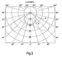
- Fig. 3 the intensity distribution in the plane of symmetry 11 is shown with a dashed line B, the distribution in the plane of drawing of Fig. 1 with a continuous line A. It is apparent, that now a small amount of light is emitted at large angles. I 87 to I 90 is about 15 cd/10001m.
- the beams B are each able to illuminate petrol stations with two rows of pumps and the paving between the rows, the luminaire producing the beams being mounted in or at the ceiling in between the rows.
- the beam A illuminates the paving as far as the beam stays within an angle of about 50° to the vertical, and signals into the distance by means of its small lobes at wider angles that the luminaire is operating and that the station is open.
- Fig. 4 shows a luminaire producing an asymmetric beam.
- the reference numerals correspond to those of Figs. 1 and 2.
- the light beam is directed to the right.
- the luminaire is suitable for illuminating an outermost row of petrol pumps of a series of rows, the left of the luminaire in Fig. 4 facing the public road.
- the plane of drawing in this Fig. coincides with the plane of symmetry 11.
Landscapes
- Engineering & Computer Science (AREA)
- General Engineering & Computer Science (AREA)
- Non-Portable Lighting Devices Or Systems Thereof (AREA)
- Non-Silver Salt Photosensitive Materials And Non-Silver Salt Photography (AREA)
Priority Applications (1)
| Application Number | Priority Date | Filing Date | Title |
|---|---|---|---|
| EP04744715A EP1656521B1 (en) | 2003-08-12 | 2004-08-03 | Luminaire and method |
Applications Claiming Priority (3)
| Application Number | Priority Date | Filing Date | Title |
|---|---|---|---|
| EP03102506 | 2003-08-12 | ||
| PCT/IB2004/051367 WO2005015078A1 (en) | 2003-08-12 | 2004-08-03 | Luminaire and method |
| EP04744715A EP1656521B1 (en) | 2003-08-12 | 2004-08-03 | Luminaire and method |
Publications (2)
| Publication Number | Publication Date |
|---|---|
| EP1656521A1 EP1656521A1 (en) | 2006-05-17 |
| EP1656521B1 true EP1656521B1 (en) | 2007-04-11 |
Family
ID=34130308
Family Applications (1)
| Application Number | Title | Priority Date | Filing Date |
|---|---|---|---|
| EP04744715A Expired - Lifetime EP1656521B1 (en) | 2003-08-12 | 2004-08-03 | Luminaire and method |
Country Status (7)
| Country | Link |
|---|---|
| US (1) | US7252412B2 (enExample) |
| EP (1) | EP1656521B1 (enExample) |
| JP (1) | JP2007502517A (enExample) |
| CN (1) | CN1836131A (enExample) |
| AT (1) | ATE359480T1 (enExample) |
| DE (1) | DE602004005872T2 (enExample) |
| WO (1) | WO2005015078A1 (enExample) |
Families Citing this family (9)
| Publication number | Priority date | Publication date | Assignee | Title |
|---|---|---|---|---|
| GB0606684D0 (en) * | 2006-04-03 | 2006-05-10 | Concord Lighting Ltd Trading A | Semi-Recessed Luminaire |
| EP2020563B1 (de) * | 2007-08-02 | 2015-01-14 | Hartmut S. Engel | Leuchte |
| JP5384615B2 (ja) | 2008-04-03 | 2014-01-08 | コーニンクレッカ フィリップス エヌ ヴェ | 天井又はキャノピの下のスペースを照らすための照明装置、及び斯様なスペースを照明する方法 |
| CN101737706B (zh) * | 2008-11-14 | 2012-02-08 | 雅马哈发动机株式会社 | 速克达型机车之灯罩及灯具结构 |
| US8576406B1 (en) | 2009-02-25 | 2013-11-05 | Physical Optics Corporation | Luminaire illumination system and method |
| MX2011011782A (es) * | 2009-05-05 | 2012-04-02 | Michael Olen Nevins | Accesorio de iluminacion de lampara de induccion. |
| WO2011125009A1 (en) * | 2010-04-09 | 2011-10-13 | Koninklijke Philips Electronics N.V. | Lighting device having a smooth cut-off |
| CN104976557A (zh) * | 2015-07-28 | 2015-10-14 | 江苏达伦电子股份有限公司 | 一种散热净化的led灯具 |
| CN105135293A (zh) * | 2015-07-28 | 2015-12-09 | 江苏达伦电子股份有限公司 | 一种空气净化功能的led灯具 |
Family Cites Families (10)
| Publication number | Priority date | Publication date | Assignee | Title |
|---|---|---|---|---|
| FR505669A (fr) * | 1917-04-19 | 1920-08-04 | Otis Angelo Mygatt | Plaques de verre pour lanterne ou phare d'automobile |
| DE1293701B (de) * | 1965-04-17 | 1969-04-30 | Siemens Ag | Breitstrahlende Strassenleuchte mit einem ovalen Spiegelreflektor |
| US4462068A (en) * | 1982-06-24 | 1984-07-24 | Manville Service Corporation | Luminaire with improved lens structure |
| EP0544651B1 (en) * | 1992-03-16 | 1997-06-18 | Koninklijke Philips Electronics N.V. | Luminaire |
| US5416683A (en) * | 1994-05-25 | 1995-05-16 | Kenall Manufacturing Co. | Drop dish lighting fixture with rectangular beam pattern |
| DE69835565T2 (de) | 1997-04-07 | 2007-08-16 | Koninklijke Philips Electronics N.V. | Leuchte |
| US6254225B1 (en) * | 1997-10-17 | 2001-07-03 | Eastman Kodak Company | Continuous ink jet printer with asymmetric heating drop deflection |
| US6053625A (en) * | 1997-11-14 | 2000-04-25 | Bowker; James W. | Lighting assembly with plurality of trapezoidal reflector faces and triangular lens faces for ceiling mounting in storage areas |
| DE69932591T2 (de) | 1998-09-17 | 2007-08-02 | Koninklijke Philips Electronics N.V. | Leuchte |
| US6250780B1 (en) * | 1999-06-30 | 2001-06-26 | Nsi Enterprises, Inc. | Indoor luminaire assembly |
-
2004
- 2004-08-03 US US10/567,694 patent/US7252412B2/en not_active Expired - Fee Related
- 2004-08-03 WO PCT/IB2004/051367 patent/WO2005015078A1/en not_active Ceased
- 2004-08-03 JP JP2006523090A patent/JP2007502517A/ja active Pending
- 2004-08-03 AT AT04744715T patent/ATE359480T1/de not_active IP Right Cessation
- 2004-08-03 DE DE602004005872T patent/DE602004005872T2/de not_active Expired - Fee Related
- 2004-08-03 CN CNA2004800229335A patent/CN1836131A/zh active Pending
- 2004-08-03 EP EP04744715A patent/EP1656521B1/en not_active Expired - Lifetime
Also Published As
| Publication number | Publication date |
|---|---|
| WO2005015078A1 (en) | 2005-02-17 |
| DE602004005872T2 (de) | 2008-01-17 |
| CN1836131A (zh) | 2006-09-20 |
| JP2007502517A (ja) | 2007-02-08 |
| DE602004005872D1 (de) | 2007-05-24 |
| US7252412B2 (en) | 2007-08-07 |
| US20060239007A1 (en) | 2006-10-26 |
| ATE359480T1 (de) | 2007-05-15 |
| EP1656521A1 (en) | 2006-05-17 |
Similar Documents
| Publication | Publication Date | Title |
|---|---|---|
| US4358816A (en) | Roadway luminaire | |
| CN1105861C (zh) | 照明装置 | |
| US4450509A (en) | Lanterns for area lighting | |
| US6443598B1 (en) | Lighting appliance with glare reducing cross blades | |
| CN100585261C (zh) | 照明装置 | |
| US2436635A (en) | Luminaire | |
| US20070133215A1 (en) | Light Fixture | |
| CN1576685A (zh) | 用于室外面板照明的改进的照明器 | |
| EP0862713B1 (en) | Luminaire | |
| KR20090012149A (ko) | 조명 기구 | |
| US7744253B2 (en) | Built-in light | |
| EP1656521B1 (en) | Luminaire and method | |
| CN1268871C (zh) | 不用薄片的照明设备 | |
| US3978332A (en) | Lighting apparatus with batwing light distribution | |
| US4751626A (en) | Reflector system for a luminaire | |
| US2875323A (en) | Outdoor lighting luminaire | |
| AU2004225784B2 (en) | Light influencing element | |
| CN217875530U (zh) | 一种用于光源倒置灯具的反光杯及光源倒置灯具 | |
| CN115930156A (zh) | 复合反射灯罩及照明灯具 | |
| GB2092734A (en) | Lanterns for Area Lighting | |
| JP2004521464A (ja) | 照明装置 | |
| CN209415237U (zh) | 一种黑板灯 | |
| US4364105A (en) | Stacked fixtures with angularly positioned lamps and downwardly light-directing reflectors | |
| NL2001447C2 (nl) | Straatverlichtingarmatuur en daarvan deel uitmakende reflector. | |
| CA1175401A (en) | Roadway luminaire |
Legal Events
| Date | Code | Title | Description |
|---|---|---|---|
| PUAI | Public reference made under article 153(3) epc to a published international application that has entered the european phase |
Free format text: ORIGINAL CODE: 0009012 |
|
| 17P | Request for examination filed |
Effective date: 20060313 |
|
| AK | Designated contracting states |
Kind code of ref document: A1 Designated state(s): AT BE BG CH CY CZ DE DK EE ES FI FR GB GR HU IE IT LI LU MC NL PL PT RO SE SI SK TR |
|
| GRAP | Despatch of communication of intention to grant a patent |
Free format text: ORIGINAL CODE: EPIDOSNIGR1 |
|
| DAX | Request for extension of the european patent (deleted) | ||
| GRAS | Grant fee paid |
Free format text: ORIGINAL CODE: EPIDOSNIGR3 |
|
| GRAA | (expected) grant |
Free format text: ORIGINAL CODE: 0009210 |
|
| AK | Designated contracting states |
Kind code of ref document: B1 Designated state(s): AT BE BG CH CY CZ DE DK EE ES FI FR GB GR HU IE IT LI LU MC NL PL PT RO SE SI SK TR |
|
| PG25 | Lapsed in a contracting state [announced via postgrant information from national office to epo] |
Ref country code: FI Free format text: LAPSE BECAUSE OF FAILURE TO SUBMIT A TRANSLATION OF THE DESCRIPTION OR TO PAY THE FEE WITHIN THE PRESCRIBED TIME-LIMIT Effective date: 20070411 Ref country code: CH Free format text: LAPSE BECAUSE OF FAILURE TO SUBMIT A TRANSLATION OF THE DESCRIPTION OR TO PAY THE FEE WITHIN THE PRESCRIBED TIME-LIMIT Effective date: 20070411 Ref country code: LI Free format text: LAPSE BECAUSE OF FAILURE TO SUBMIT A TRANSLATION OF THE DESCRIPTION OR TO PAY THE FEE WITHIN THE PRESCRIBED TIME-LIMIT Effective date: 20070411 Ref country code: SI Free format text: LAPSE BECAUSE OF FAILURE TO SUBMIT A TRANSLATION OF THE DESCRIPTION OR TO PAY THE FEE WITHIN THE PRESCRIBED TIME-LIMIT Effective date: 20070411 |
|
| REG | Reference to a national code |
Ref country code: GB Ref legal event code: FG4D |
|
| REG | Reference to a national code |
Ref country code: CH Ref legal event code: EP |
|
| REG | Reference to a national code |
Ref country code: IE Ref legal event code: FG4D |
|
| REF | Corresponds to: |
Ref document number: 602004005872 Country of ref document: DE Date of ref document: 20070524 Kind code of ref document: P |
|
| REG | Reference to a national code |
Ref country code: GB Ref legal event code: 746 Effective date: 20070515 |
|
| PG25 | Lapsed in a contracting state [announced via postgrant information from national office to epo] |
Ref country code: SE Free format text: LAPSE BECAUSE OF FAILURE TO SUBMIT A TRANSLATION OF THE DESCRIPTION OR TO PAY THE FEE WITHIN THE PRESCRIBED TIME-LIMIT Effective date: 20070711 |
|
| PG25 | Lapsed in a contracting state [announced via postgrant information from national office to epo] |
Ref country code: ES Free format text: LAPSE BECAUSE OF FAILURE TO SUBMIT A TRANSLATION OF THE DESCRIPTION OR TO PAY THE FEE WITHIN THE PRESCRIBED TIME-LIMIT Effective date: 20070722 |
|
| PG25 | Lapsed in a contracting state [announced via postgrant information from national office to epo] |
Ref country code: PT Free format text: LAPSE BECAUSE OF FAILURE TO SUBMIT A TRANSLATION OF THE DESCRIPTION OR TO PAY THE FEE WITHIN THE PRESCRIBED TIME-LIMIT Effective date: 20070911 |
|
| ET | Fr: translation filed | ||
| REG | Reference to a national code |
Ref country code: CH Ref legal event code: PL |
|
| PG25 | Lapsed in a contracting state [announced via postgrant information from national office to epo] |
Ref country code: PL Free format text: LAPSE BECAUSE OF FAILURE TO SUBMIT A TRANSLATION OF THE DESCRIPTION OR TO PAY THE FEE WITHIN THE PRESCRIBED TIME-LIMIT Effective date: 20070411 Ref country code: AT Free format text: LAPSE BECAUSE OF FAILURE TO SUBMIT A TRANSLATION OF THE DESCRIPTION OR TO PAY THE FEE WITHIN THE PRESCRIBED TIME-LIMIT Effective date: 20070411 |
|
| PG25 | Lapsed in a contracting state [announced via postgrant information from national office to epo] |
Ref country code: BE Free format text: LAPSE BECAUSE OF FAILURE TO SUBMIT A TRANSLATION OF THE DESCRIPTION OR TO PAY THE FEE WITHIN THE PRESCRIBED TIME-LIMIT Effective date: 20070411 |
|
| PG25 | Lapsed in a contracting state [announced via postgrant information from national office to epo] |
Ref country code: BG Free format text: LAPSE BECAUSE OF FAILURE TO SUBMIT A TRANSLATION OF THE DESCRIPTION OR TO PAY THE FEE WITHIN THE PRESCRIBED TIME-LIMIT Effective date: 20070711 Ref country code: CZ Free format text: LAPSE BECAUSE OF FAILURE TO SUBMIT A TRANSLATION OF THE DESCRIPTION OR TO PAY THE FEE WITHIN THE PRESCRIBED TIME-LIMIT Effective date: 20070411 Ref country code: DK Free format text: LAPSE BECAUSE OF FAILURE TO SUBMIT A TRANSLATION OF THE DESCRIPTION OR TO PAY THE FEE WITHIN THE PRESCRIBED TIME-LIMIT Effective date: 20070411 |
|
| PGFP | Annual fee paid to national office [announced via postgrant information from national office to epo] |
Ref country code: DE Payment date: 20071015 Year of fee payment: 4 |
|
| PLBE | No opposition filed within time limit |
Free format text: ORIGINAL CODE: 0009261 |
|
| STAA | Information on the status of an ep patent application or granted ep patent |
Free format text: STATUS: NO OPPOSITION FILED WITHIN TIME LIMIT |
|
| PG25 | Lapsed in a contracting state [announced via postgrant information from national office to epo] |
Ref country code: SK Free format text: LAPSE BECAUSE OF FAILURE TO SUBMIT A TRANSLATION OF THE DESCRIPTION OR TO PAY THE FEE WITHIN THE PRESCRIBED TIME-LIMIT Effective date: 20070411 |
|
| 26N | No opposition filed |
Effective date: 20080114 |
|
| PG25 | Lapsed in a contracting state [announced via postgrant information from national office to epo] |
Ref country code: GR Free format text: LAPSE BECAUSE OF FAILURE TO SUBMIT A TRANSLATION OF THE DESCRIPTION OR TO PAY THE FEE WITHIN THE PRESCRIBED TIME-LIMIT Effective date: 20070712 Ref country code: MC Free format text: LAPSE BECAUSE OF NON-PAYMENT OF DUE FEES Effective date: 20070831 |
|
| PGFP | Annual fee paid to national office [announced via postgrant information from national office to epo] |
Ref country code: FR Payment date: 20070807 Year of fee payment: 4 |
|
| PG25 | Lapsed in a contracting state [announced via postgrant information from national office to epo] |
Ref country code: RO Free format text: LAPSE BECAUSE OF FAILURE TO SUBMIT A TRANSLATION OF THE DESCRIPTION OR TO PAY THE FEE WITHIN THE PRESCRIBED TIME-LIMIT Effective date: 20070411 |
|
| PG25 | Lapsed in a contracting state [announced via postgrant information from national office to epo] |
Ref country code: IE Free format text: LAPSE BECAUSE OF NON-PAYMENT OF DUE FEES Effective date: 20070803 |
|
| PG25 | Lapsed in a contracting state [announced via postgrant information from national office to epo] |
Ref country code: EE Free format text: LAPSE BECAUSE OF FAILURE TO SUBMIT A TRANSLATION OF THE DESCRIPTION OR TO PAY THE FEE WITHIN THE PRESCRIBED TIME-LIMIT Effective date: 20070411 |
|
| GBPC | Gb: european patent ceased through non-payment of renewal fee |
Effective date: 20080803 |
|
| NLV4 | Nl: lapsed or anulled due to non-payment of the annual fee |
Effective date: 20090301 |
|
| PG25 | Lapsed in a contracting state [announced via postgrant information from national office to epo] |
Ref country code: NL Free format text: LAPSE BECAUSE OF NON-PAYMENT OF DUE FEES Effective date: 20090301 |
|
| REG | Reference to a national code |
Ref country code: FR Ref legal event code: ST Effective date: 20090430 |
|
| PG25 | Lapsed in a contracting state [announced via postgrant information from national office to epo] |
Ref country code: CY Free format text: LAPSE BECAUSE OF FAILURE TO SUBMIT A TRANSLATION OF THE DESCRIPTION OR TO PAY THE FEE WITHIN THE PRESCRIBED TIME-LIMIT Effective date: 20070411 |
|
| PG25 | Lapsed in a contracting state [announced via postgrant information from national office to epo] |
Ref country code: DE Free format text: LAPSE BECAUSE OF NON-PAYMENT OF DUE FEES Effective date: 20090303 Ref country code: FR Free format text: LAPSE BECAUSE OF NON-PAYMENT OF DUE FEES Effective date: 20080901 Ref country code: LU Free format text: LAPSE BECAUSE OF NON-PAYMENT OF DUE FEES Effective date: 20070803 |
|
| PG25 | Lapsed in a contracting state [announced via postgrant information from national office to epo] |
Ref country code: HU Free format text: LAPSE BECAUSE OF FAILURE TO SUBMIT A TRANSLATION OF THE DESCRIPTION OR TO PAY THE FEE WITHIN THE PRESCRIBED TIME-LIMIT Effective date: 20071012 Ref country code: TR Free format text: LAPSE BECAUSE OF FAILURE TO SUBMIT A TRANSLATION OF THE DESCRIPTION OR TO PAY THE FEE WITHIN THE PRESCRIBED TIME-LIMIT Effective date: 20070411 |
|
| PG25 | Lapsed in a contracting state [announced via postgrant information from national office to epo] |
Ref country code: GB Free format text: LAPSE BECAUSE OF NON-PAYMENT OF DUE FEES Effective date: 20080803 |
|
| PGFP | Annual fee paid to national office [announced via postgrant information from national office to epo] |
Ref country code: IT Payment date: 20070831 Year of fee payment: 4 |