EP1656502B1 - Eccentric screw pump equipped with a rotor that is erosion-resistant - Google Patents
Eccentric screw pump equipped with a rotor that is erosion-resistant Download PDFInfo
- Publication number
- EP1656502B1 EP1656502B1 EP04764133A EP04764133A EP1656502B1 EP 1656502 B1 EP1656502 B1 EP 1656502B1 EP 04764133 A EP04764133 A EP 04764133A EP 04764133 A EP04764133 A EP 04764133A EP 1656502 B1 EP1656502 B1 EP 1656502B1
- Authority
- EP
- European Patent Office
- Prior art keywords
- eccentric screw
- motor according
- screw pump
- eccentric
- screw motor
- Prior art date
- Legal status (The legal status is an assumption and is not a legal conclusion. Google has not performed a legal analysis and makes no representation as to the accuracy of the status listed.)
- Not-in-force
Links
- 230000003628 erosive effect Effects 0.000 title description 7
- 239000000463 material Substances 0.000 claims abstract description 16
- 238000005260 corrosion Methods 0.000 claims abstract description 7
- 230000007797 corrosion Effects 0.000 claims abstract description 7
- 238000005299 abrasion Methods 0.000 claims abstract description 6
- 239000002184 metal Substances 0.000 claims description 30
- 238000000034 method Methods 0.000 claims description 22
- 229910000831 Steel Inorganic materials 0.000 claims description 18
- 239000010959 steel Substances 0.000 claims description 18
- 238000004804 winding Methods 0.000 claims description 10
- 230000002093 peripheral effect Effects 0.000 claims description 7
- 238000004519 manufacturing process Methods 0.000 claims description 4
- 230000008878 coupling Effects 0.000 claims description 3
- 238000010168 coupling process Methods 0.000 claims description 3
- 238000005859 coupling reaction Methods 0.000 claims description 3
- 239000007787 solid Substances 0.000 claims description 2
- 150000001875 compounds Chemical class 0.000 claims 3
- 238000003825 pressing Methods 0.000 claims 1
- 210000001503 joint Anatomy 0.000 description 7
- 239000010935 stainless steel Substances 0.000 description 4
- 229910001220 stainless steel Inorganic materials 0.000 description 4
- 238000003466 welding Methods 0.000 description 4
- 238000005096 rolling process Methods 0.000 description 3
- 238000001816 cooling Methods 0.000 description 2
- 238000006073 displacement reaction Methods 0.000 description 2
- 239000013536 elastomeric material Substances 0.000 description 2
- 239000011347 resin Substances 0.000 description 2
- 229920005989 resin Polymers 0.000 description 2
- 229910000851 Alloy steel Inorganic materials 0.000 description 1
- 244000043261 Hevea brasiliensis Species 0.000 description 1
- 230000004323 axial length Effects 0.000 description 1
- 239000011248 coating agent Substances 0.000 description 1
- 238000000576 coating method Methods 0.000 description 1
- 238000010276 construction Methods 0.000 description 1
- 238000011161 development Methods 0.000 description 1
- 230000018109 developmental process Effects 0.000 description 1
- 230000000694 effects Effects 0.000 description 1
- 230000001747 exhibiting effect Effects 0.000 description 1
- 239000000945 filler Substances 0.000 description 1
- 230000005484 gravity Effects 0.000 description 1
- 229910001092 metal group alloy Inorganic materials 0.000 description 1
- 238000012986 modification Methods 0.000 description 1
- 230000004048 modification Effects 0.000 description 1
- 229920003052 natural elastomer Polymers 0.000 description 1
- 229920001194 natural rubber Polymers 0.000 description 1
- 239000002245 particle Substances 0.000 description 1
- 230000035515 penetration Effects 0.000 description 1
- 238000007747 plating Methods 0.000 description 1
- 239000000843 powder Substances 0.000 description 1
- 230000002250 progressing effect Effects 0.000 description 1
- 239000003566 sealing material Substances 0.000 description 1
- 239000011265 semifinished product Substances 0.000 description 1
- 238000005482 strain hardening Methods 0.000 description 1
- 229920002994 synthetic fiber Polymers 0.000 description 1
Images
Classifications
-
- F—MECHANICAL ENGINEERING; LIGHTING; HEATING; WEAPONS; BLASTING
- F04—POSITIVE - DISPLACEMENT MACHINES FOR LIQUIDS; PUMPS FOR LIQUIDS OR ELASTIC FLUIDS
- F04C—ROTARY-PISTON, OR OSCILLATING-PISTON, POSITIVE-DISPLACEMENT MACHINES FOR LIQUIDS; ROTARY-PISTON, OR OSCILLATING-PISTON, POSITIVE-DISPLACEMENT PUMPS
- F04C2/00—Rotary-piston machines or pumps
- F04C2/08—Rotary-piston machines or pumps of intermeshing-engagement type, i.e. with engagement of co-operating members similar to that of toothed gearing
- F04C2/10—Rotary-piston machines or pumps of intermeshing-engagement type, i.e. with engagement of co-operating members similar to that of toothed gearing of internal-axis type with the outer member having more teeth or tooth-equivalents, e.g. rollers, than the inner member
- F04C2/107—Rotary-piston machines or pumps of intermeshing-engagement type, i.e. with engagement of co-operating members similar to that of toothed gearing of internal-axis type with the outer member having more teeth or tooth-equivalents, e.g. rollers, than the inner member with helical teeth
- F04C2/1071—Rotary-piston machines or pumps of intermeshing-engagement type, i.e. with engagement of co-operating members similar to that of toothed gearing of internal-axis type with the outer member having more teeth or tooth-equivalents, e.g. rollers, than the inner member with helical teeth the inner and outer member having a different number of threads and one of the two being made of elastic materials, e.g. Moineau type
-
- F—MECHANICAL ENGINEERING; LIGHTING; HEATING; WEAPONS; BLASTING
- F04—POSITIVE - DISPLACEMENT MACHINES FOR LIQUIDS; PUMPS FOR LIQUIDS OR ELASTIC FLUIDS
- F04C—ROTARY-PISTON, OR OSCILLATING-PISTON, POSITIVE-DISPLACEMENT MACHINES FOR LIQUIDS; ROTARY-PISTON, OR OSCILLATING-PISTON, POSITIVE-DISPLACEMENT PUMPS
- F04C2230/00—Manufacture
- F04C2230/20—Manufacture essentially without removing material
- F04C2230/23—Manufacture essentially without removing material by permanently joining parts together
- F04C2230/231—Manufacture essentially without removing material by permanently joining parts together by welding
-
- F—MECHANICAL ENGINEERING; LIGHTING; HEATING; WEAPONS; BLASTING
- F04—POSITIVE - DISPLACEMENT MACHINES FOR LIQUIDS; PUMPS FOR LIQUIDS OR ELASTIC FLUIDS
- F04C—ROTARY-PISTON, OR OSCILLATING-PISTON, POSITIVE-DISPLACEMENT MACHINES FOR LIQUIDS; ROTARY-PISTON, OR OSCILLATING-PISTON, POSITIVE-DISPLACEMENT PUMPS
- F04C2240/00—Components
- F04C2240/20—Rotors
-
- Y—GENERAL TAGGING OF NEW TECHNOLOGICAL DEVELOPMENTS; GENERAL TAGGING OF CROSS-SECTIONAL TECHNOLOGIES SPANNING OVER SEVERAL SECTIONS OF THE IPC; TECHNICAL SUBJECTS COVERED BY FORMER USPC CROSS-REFERENCE ART COLLECTIONS [XRACs] AND DIGESTS
- Y10—TECHNICAL SUBJECTS COVERED BY FORMER USPC
- Y10T—TECHNICAL SUBJECTS COVERED BY FORMER US CLASSIFICATION
- Y10T29/00—Metal working
- Y10T29/49—Method of mechanical manufacture
- Y10T29/49229—Prime mover or fluid pump making
- Y10T29/49236—Fluid pump or compressor making
- Y10T29/49242—Screw or gear type, e.g., Moineau type
-
- Y—GENERAL TAGGING OF NEW TECHNOLOGICAL DEVELOPMENTS; GENERAL TAGGING OF CROSS-SECTIONAL TECHNOLOGIES SPANNING OVER SEVERAL SECTIONS OF THE IPC; TECHNICAL SUBJECTS COVERED BY FORMER USPC CROSS-REFERENCE ART COLLECTIONS [XRACs] AND DIGESTS
- Y10—TECHNICAL SUBJECTS COVERED BY FORMER USPC
- Y10T—TECHNICAL SUBJECTS COVERED BY FORMER US CLASSIFICATION
- Y10T29/00—Metal working
- Y10T29/49—Method of mechanical manufacture
- Y10T29/49826—Assembling or joining
- Y10T29/49863—Assembling or joining with prestressing of part
- Y10T29/49865—Assembling or joining with prestressing of part by temperature differential [e.g., shrink fit]
Definitions
- the pump or the motor has a stator with a continuous helical opening in which the rotor rolls in the displacement mode.
- the stator forms a cylindrical tube which is provided with an elastomeric lining.
- the elastomeric lining itself constitutes the wall of the through-hole and acts as a seal against the stator.
- the stator is composed of a core element and a shell formed around it.
- the jacket is cold formed starting from a cylindrical tube in the helical shape. This preserves the original cylindrical Tube not only the helical shape as it is required for the rotor, but the tube is thus firmly connected to the core element.
- the thread valleys of the jacket of the stator are firmly and frictionally on the core element.
- the carrier element may still be provided with longitudinal ribs.
- the known rotor is inexpensive to produce in very large quantities. Lengths of up to 6 meters can easily be achieved without the need for a chipping rework of the surface of the stator.
- the surface of the rotor is very smooth and sufficiently dimensionally stable.
- the core element present in the shell prevents the rotor from becoming desorbed when pressurized, which would lead to a pitch error between the stator and rotor and the consequent leakage.
- the steel material hitherto used for the known rotor is not strong enough for a number of applications with regard to the abrasion occurring and, for some applications, also not sufficiently resistant to corrosion.
- the known rotor is not characterized by a sufficient erosion resistance. Erosion should not only be understood to mean the removal by corrosion, but also the removal by vibratory grinding of the material being conveyed on the surface.
- stator with a jacket, which also shows a helical shape similar to a helical shape of the through hole.
- the elastomeric lining which in turn serves as a sealing material, in these cases has virtually a nearly constant wall thickness.
- the method is characterized by the features of claim 23.
- the rotor is sandwiched. It consists of a radially inner layer and a radially outer layer, wherein the radially outer layer is specially adapted to the higher erosion resistance. It may be more resistant to abrasion or corrosion, or both, than the radially inner layer.
- the radially inner layer can be selected primarily from the viewpoint of strength and cost, so that with a very thin radial outer layer the death is found.
- a very homogeneous structure of the rotor can be achieved if the inner tube is a seamless tube. Inhomogeneities, as they would otherwise occur during welding, thereby avoided. Such inhomogeneities could continue as a form error to the outside.
- a wound tube is also possible.
- the tube is preferably laser welded. The helix should run in opposite directions to the helix of the outer layer.
- the inner layer, or the inner tube consists of an easily deformable steel, which is well suited to dissipate the forces occurring and can be cold formed in a useful manner.
- the outer layer may consist of an attached tube.
- such a solution is only suitable for rotors with a short overall length.
- the metal strip is wound on impact in such a way that the individual turns adjoin each other without a gap.
- a particularly good arrangement is achieved if before the cold forming the helical joint, on which the turns abut each other, is welded.
- the welding is done by means of laser.
- Stainless steel V2A, V4A steel or other abrasion-resistant steels may be considered as external material. Since these have a much higher specific gravity than normal steel, the two-layer construction also means a weight saving compared to a rotor made only of stainless steel. This certainly plays a role in rotors with a length of up to 6 meters.
- the strength of the rotor can be improved if it has a core element.
- the rotor may be molded around the core member to provide a good bond with the core member.
- the core element prevents long rotation of the rotor under load.
- additional torque can be introduced over the length of the rotor.
- the substantially Rotationsssymentwitz and not helically deformed core is better suited.
- the core element may itself be tubular or solid.
- the gap between the tube or shell of the rotor and the core element can either be left blank or filled with a mass.
- a cylindrical tube is first provided.
- the tube is covered with a metal layer, so that a double-walled structure is obtained.
- the double-walled structure which is still cylindrical, helically deformed.
- the coating of the cylindrical tube with the outer layer is very simple and can also be done simply because of the simple geometric shape of the tube provided.
- outer layer Since the outer layer must be applied only with a smaller wall thickness, because the stability of the rotor may be generated in the first place of the inner tube, materials can be used for the outer layer, which would no longer be cold to deform at high wall thickness ,
- a seamless tube is used in the method according to the invention.
- the seamless tube has expediently a metallically bright surface, so that the connection of the outer layer with the tube by the cold forming is not hindered by oxydschreibtex.
- the outer metal layer consists in the simplest case of a metal strip which is wound onto the tube.
- the metal strip can be heated immediately before the contact point before being wound up. The subsequent cooling ensures a shrinkage process that holds the metal strip particularly firmly on the surface of the tube.
- the butt joint between adjacent turns is suitably welded to prevent penetration of particles.
- the resulting double-walled structure is cold formed.
- the outer layer joins the inner tube, similar to the case of leafing.
- the connection is therefore particularly durable and will not open even with temperature changes.
- a core element may be inserted before forming the coated tube.
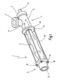
- the eccentric screw pump 1 shows a schematic, perspective illustration of an eccentric screw pump 1 according to the invention.
- the eccentric screw pump 1 includes a pump head 2, a stator 3 in which a rotor 4 illustrated in FIG. 2 rotates, and a connection head 5.
- the pump head 2 has a substantially cylindrical housing 6 which is provided at one end with a cover 7, through which a drive shaft 8 is guided outwardly sealed.
- a connection piece 9 which ends at a mounting flange 11.
- a coupling piece to the drive shaft 8 which is connected to a drive motor, not shown, with the rotor 4 rotatably to couple.
- the front end of the housing 6 remote from the cover 7 is provided with a clamping flange 12 whose diameter is greater than the diameter of the substantially cylindrical housing 6.
- the clamping flange 12 includes a stepped bore 13 which is aligned with the interior of the housing 6. In the stepped bore an unrecognizable investment shoulder is formed, against which the stator 3 is pressed with one end.
- connection head 5 has a cooperating with the clamping flange 12 clamping flange 14, which also includes a stepped bore in which the other end of the stator 3 is inserted. With the stepped bore a wegsumde pipe 15 is aligned.
- the stator 3 is tightened sealed by means of a total of 4 tie rods 16.
- the two clamping flanges 12 and 14 are provided with four mutually aligned holes 17 which lie on a pitch circle, which is larger than the outer diameter of the housing 6 and the tube 15. Through these holes 17 lead rod-shaped tie rod 16 therethrough.
- nuts 18 are screwed onto the tie rods, with the help of the two clamping flanges 12 and 14 are tightened towards each other.
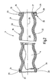
- the stator 3 is, as shown in FIG. 2 shows a tubular jacket 19 with a constant wall thickness, which surrounds an interior space 20.
- the jacket 19 is made of steel, a steel alloy, light metal or a light metal alloy. It is shaped so that its inner wall 21 gets the outer shape of a multi-start screw. Its outer side 22 has a correspondingly similar shape with a diameter corresponding to the wall thickness of the shell 19 is greater than the diameter of the interior of the shell 19th
- the jacket 19 terminates at its ends with end faces 23 and 24 which extend at right angles to its longitudinal axis 25.
- the longitudinal axis 25 is the axis of the interior 20.
- the interior 20 has the shape a double-threaded screw.
- the cross section which is surrounded by the outer surface 22, each seen at right angles to the longitudinal axis 25, the shape of an oval, similar to a racetrack.
- the ends can also be formed into cylindrical tubes.
- the end ring 26 includes a through hole 27, which coincides with the course of the outer surface 22 over the length of the end ring 26.
- the end ring 26 acts in the broadest sense as a nut, which is screwed onto the thread, which is defined by the jacket 19.
- the length of the thread corresponds to the thickness of the end ring 26.
- end ring 26 Radially outwardly, the end ring 26 is bounded by a cylindrical surface 28 which merges in the axial direction into a plane surface 29 facing away from the shell 19.
- the liner 32 is made of an elastically resilient, preferably elastomeric material, such as natural rubber or synthetic material, and has approximately the same wall thickness at each location.
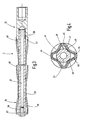
- the rotor 4 is composed of a core element 33, a rotor shell 34 and a coupling head 35.
- the core element 33 is in the illustrated embodiment, a thick-walled steel tube with an at least originally cylindrical outer peripheral surface 36 and a continuous cylindrical interior 37.
- the core element 33 is straight and therefore tubular in shape, because the interior does not provide any appreciable contribution to the strength in question, but only adds weight. But it can also be massive.
- the core member 33 At its right in Fig. 3 end of the core member 33 is provided with a threaded pin 38. At the opposite end, the core member 33 includes a threaded bore 39.
- the jacket 34 of the rotor 4 is also a tube with an inner wall 40 and an outer surface 41.
- the outer surface 41 forms a thread that continues over the entire axial length of the jacket 34. It begins at 42 and ends at 43.
- the number of turns of the thread formed by the outer surface 41 is one less than the number of turns of the through-hole 20 in the stator. 3
- the rotor 4 in the embodiment shown has a four-start thread, i. along the mantle 34 extend helically a total of four strips. Since the passage opening 20 is correspondingly five continuous, forms the five-start thread in the through hole 20 a total of five helically extending strips of elastomeric material.
- the rotor shell 34 has two layers and consists of an inner layer 44 and an outer layer located thereon Layer 45.
- the inner layer 44 consists of an originally cylindrical steel tube with good ductility and a strength suitable for the application.
- the outer layer 45 consists of an erosion-resistant material, that is, a material that is little worn or abraded by the medium to be pumped and / or that is chemically attacked by the medium to be pumped little.
- a suitable material is for example stainless steel such as a V2A or a V4A.
- the wall thickness of the inner layer 44 is between 1 mm and 5 mm, while the wall thickness of the outer layer 45 can be between 1 mm and also 5 mm. The production of this rotor 4 is explained below with reference to FIG 5.
- the shell 34 is, as already mentioned, tubular, which is why the inner surface 40 of the outer surface 41 follows at a constant distance.
- the dimensions of the cylindrical straight tube, from which the jacket 34 is cold worked, are selected such that after the final deformation to the helical shape of the shell 34 with its inner peripheral surface 40 in the region of the thread valleys 47 (relative to the outer contour), the outer peripheral surface 36th of the core element 33 at least touched.
- the semifinished product as mentioned, from which the jacket 34 is made, a cylindrical tube whose diameter is larger than the outer diameter of the core member 33, between the core member 33 and the shell 34 helically extending gaps 49.
- the number of these helical spaces 49 is equal to the number of thread crests 46, which can be seen in the cross section of the rotor 4 in the circumferential direction.
- these spaces 49 can either remain empty or filled with a mass. This mass can e.g. Resin or filled with light metal powder resin.
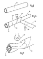
- the production method of the rotor 4 consisting of the layers 44 and 45 is illustrated in a very schematic manner in FIGS. 5 to 7.
- the steel tube 51 is wound on the outside with a metal strip 52, which later forms the outer layer 45.
- the metal band 52 is a band of a corresponding stainless steel or other steel.
- the band 42 is wound on the outside of the steel tube 51 as a catchy screw. In this case, it forms adjacent turns 53, which are separated by a respective helically extending butt joint 54. The winding of the metal strip 52 is done so that the butt joint 54 is closed as possible.
- the butt joint 54 is welded during winding or in a separate step by means of a laser beam 55 and filler material to achieve a smooth, homogeneous cylindrical surface. Other welding methods are also possible. It can be welded through to connect the band 52 in the region of the butt joint 54 with the support tube 51 cohesively.
- the metal strip 52 Immediately before the metal strip 52 impinges on the tube 51, it is heated, for example by means of a gas flame 56 or inductively. This ensures that the metal strip 52 generates a considerable tension in the circumferential direction after winding on the tube 51 and the cooling.
- the core element 33 is inserted according to FIG. Subsequently, the structure by cold deformation, for example, rolls by means of a variety of rollers, of which only one is indicated at 57, brought in the desired helical shape.
- the metal strip 52 connects very intimately with the outer surface of the underlying steel tube 51st
- the metal strip 52 forms, after the step of Figure 6 is completed, on the metal steel tube 51, a second, outer tube which sits firmly and under tension in the circumferential direction frictionally on the outer peripheral surface of the tube 51.
- the two tubes namely the tube formed by winding and the seamless, inner steel tube are so firmly connected to each other after winding that they are no longer separated.
- the subsequent rolling process according to FIG. 7 ensures an even more intimate bond, which at least to a certain extent resembles the plating of a metal layer.
- the outer, made by winding pipe does not separate from the underlying tube 51. Rather, both are formed together in the desired helical shape, at the same time also the intimate connection with the core element 33 is produced.
- metal bands can be wound up as a multi-start screw. Furthermore, the winding process can be repeated to create several layers one above the other.
Abstract
Description
Aus der
Die Pumpe beziehungsweise der Motor weist einen Stator mit einer durchgehenden schraubenförmigen Öffnung auf, in der der Rotor sich beim Verdrängerbetrieb abwälzt. Den Stator bildet ein zylindrisches Rohr, das mit einer elastomeren Auskleidung versehen ist. Die elastomere Auskleidung selbst stellt die Wand der Durchgangsöffnung dar und wirkt als Abdichtung gegenüber dem Stator.The pump or the motor has a stator with a continuous helical opening in which the rotor rolls in the displacement mode. The stator forms a cylindrical tube which is provided with an elastomeric lining. The elastomeric lining itself constitutes the wall of the through-hole and acts as a seal against the stator.
Der Stator setzt sich aus einem Kernelement und einem darum geformten Mantel zusammen. Der Mantel wird ausgehend von einem zylindrischen Rohr in die schraubenförmige Gestalt kalt umgeformt. Dadurch erhält das ursprünglich zylindrische Rohr nicht nur die schraubenförmige Gestalt, wie sie für den Rotor erforderlich ist, sondern das Rohr wird auf diese Weise auch fest mit dem Kernelement verbunden. Im endgültigen Zustand liegen die Gewindetäler des Mantels des Stators fest und reibschlüssig auf dem Kernelement auf. Zur Verbesserung der Mitnahmewirkung zwischen dem Kernelement und dem Mantel des Stators, kann das Trägerelement noch mit Längsrippen versehen sein.The stator is composed of a core element and a shell formed around it. The jacket is cold formed starting from a cylindrical tube in the helical shape. This preserves the original cylindrical Tube not only the helical shape as it is required for the rotor, but the tube is thus firmly connected to the core element. In the final state, the thread valleys of the jacket of the stator are firmly and frictionally on the core element. To improve the entrainment effect between the core element and the jacket of the stator, the carrier element may still be provided with longitudinal ribs.
Der bekannte Rotor ist kostengünstig in sehr großen Mengen herstellbar. Es können ohne weiteres Längen von bis zu 6 Metern erreicht werden, ohne das eine spangebende Nacharbeit der Oberfläche des Stators erforderlich ist. Die Oberfläche des Rotors ist sehr glatt und hinreichend maßhaltig.The known rotor is inexpensive to produce in very large quantities. Lengths of up to 6 meters can easily be achieved without the need for a chipping rework of the surface of the stator. The surface of the rotor is very smooth and sufficiently dimensionally stable.
Das in dem Mantel vorhandene Kernelement verhindert, dass sich der Rotor bei Druckbeaufschlagung entspiralisiert, was zu einem Steigungsfehler zwischen Stator und Rotor und der Folge entsprechender Undichtigkeiten führen würde.The core element present in the shell prevents the rotor from becoming desorbed when pressurized, which would lead to a pitch error between the stator and rotor and the consequent leakage.
Das bislang für den bekannten Rotor verwendete Stahlmaterial ist für eine Reihe von Anwendungen nicht fest genug hinsichtlich des auftretenden Abriebs und für einige Anwendungsfälle auch nicht hinreichend korrosionsfest. Mit anderen Worten, der bekannte Rotor zeichnet sich nicht durch eine ausreichende Erosionsfestigkeit aus. Dabei soll unter Erosion nicht nur der Abtrag durch Korrosion, sondern auch der Abtrag durch Gleitschleifen des geförderten Materials an der Oberfläche verstanden werden.The steel material hitherto used for the known rotor is not strong enough for a number of applications with regard to the abrasion occurring and, for some applications, also not sufficiently resistant to corrosion. In other words, the known rotor is not characterized by a sufficient erosion resistance. Erosion should not only be understood to mean the removal by corrosion, but also the removal by vibratory grinding of the material being conveyed on the surface.
Aus dem Stand der Technik ist es ferner bekannt, den Stator mit einem Mantel zu versehen, der ebenfalls eine schraubenförmige Gestalt ähnlich einer schraubenförmigen Gestalt der Durchgangsöffnung zeigt. Die elastomere Auskleidung, die wiederum als Dichtmaterial dient, weist in diesen Fällen praktisch eine nahezu konstante Wandstärke auf. Mit einem solchen Stator lassen sich größere Drücke erzeugen, beziehungsweise größere Drehmomente im Falle eines Exzenterschneckenmotors.It is also known from the prior art, the To provide stator with a jacket, which also shows a helical shape similar to a helical shape of the through hole. The elastomeric lining, which in turn serves as a sealing material, in these cases has virtually a nearly constant wall thickness. With such a stator, larger pressures can be generated, or larger torques in the case of an eccentric screw motor.
Ausgehend hiervon ist es Aufgabe der Erfindung eine Exzenterschneckenpumpe oder einen Exzenterschneckenmotor zu schaffen, bei denen der Rotor sich durch eine bessere Erosionsfestigkeit auszeichnet.Based on this, it is an object of the invention to provide an eccentric screw pump or an eccentric screw motor, in which the rotor is characterized by a better erosion resistance.
Diese Aufgabe wird erfindungsgemäß mit dem Exzenterschneckenmotor oder der Exzenterschneckenpumpe mit den Merkmalen des Anspruches 1 gelöst.This object is achieved with the eccentric screw motor or the eccentric screw pump with the features of claim 1.
Ferner ist es Aufgabe der Erfindung ein Verfahren zu schaffen, um einen Rotor zu produzieren, der eine größere Erosionsfestigkeit zeigt.It is another object of the invention to provide a method to produce a rotor exhibiting greater erosion resistance.
Das Verfahren ist durch die Merkmale des Anspruchs 23 gekennzeichnet.The method is characterized by the features of
Bei der erfindungsgemäßen Exzenterschneckenpumpe beziehungsweise dem erfindungsgemäßen Exzenterschneckenmotor ist der Rotor sandwichartig aufgebaut. Er besteht aus einer radial inneren Lage und einer radial äußeren Lage, wobei die radial äußere Lage speziell an die höhere Erosionsfestigkeit angepasst ist. Sie kann abriebfester oder korrosionsfester oder beides sein, als die radial innere Lage.In the eccentric screw pump according to the invention or the eccentric screw motor according to the invention, the rotor is sandwiched. It consists of a radially inner layer and a radially outer layer, wherein the radially outer layer is specially adapted to the higher erosion resistance. It may be more resistant to abrasion or corrosion, or both, than the radially inner layer.
Da im Übrigen die korrosionsfestere Materialien sich bei größerer Wandstärke unter Umständen schlechter umformen lassen und/oder sehr viel teurer sind als die radial innere Lage, kann die radial innere Lage primär nach dem Gesichtspunkt der Festigkeit und der Kosten ausgewählt werden, so dass mit einer sehr dünnen radialen äußeren Lage das Auskommen gefunden wird.Incidentally, since the more corrosion-resistant materials can be worse form worse with larger wall thickness and / or are much more expensive than the radially inner layer, the radially inner layer can be selected primarily from the viewpoint of strength and cost, so that with a very thin radial outer layer the livelihood is found.
Eine sehr homogene Struktur des Rotors lässt sich erreichen, wenn das innere Rohr ein nahtloses Rohr ist. Inhomogenitäten, wie sie sonst beim Schweißen auftreten würden, werden dadurch vermieden. Solche Inhomogenitäten könnten sich als Gestaltsfehler nach außen hin fortsetzen. Es ist jedoch auch möglich ein gewickeltes Rohr als inneres Rohr zu verwenden. An der schraubenförmigen Stoßfuge ist das Rohr vorzugsweise Laser geschweißt. Die Wendel sollte gegenläufig zu der Wendel der äußeren Lage laufen.A very homogeneous structure of the rotor can be achieved if the inner tube is a seamless tube. Inhomogeneities, as they would otherwise occur during welding, thereby avoided. Such inhomogeneities could continue as a form error to the outside. However, it is also possible to use a wound tube as the inner tube. At the helical butt joint, the tube is preferably laser welded. The helix should run in opposite directions to the helix of the outer layer.
Die innere Lage, beziehungsweise das innere Rohr, besteht aus einem leicht umformbaren Stahl, der gut geeignet ist, die auftretenden Kräfte abzuleiten und der sich in brauchbarer Weise kalt umformen lässt.The inner layer, or the inner tube, consists of an easily deformable steel, which is well suited to dissipate the forces occurring and can be cold formed in a useful manner.
Die äußere Schicht kann aus einem aufgesteckten Rohr bestehen. Eine solche Lösung eignet sich jedoch nur für Rotoren mit kurzer Baulänge. Bei Rotoren mit großer Baulänge ist es von Vorteil, wenn die äußere Lage von einem aufgewickelten Metallband gebildet wird.The outer layer may consist of an attached tube. However, such a solution is only suitable for rotors with a short overall length. For rotors with a large overall length, it is advantageous if the outer layer is formed by a wound-up metal strip.
Das Metallband wird auf Stoß aufgewickelt derart, dass die einzelnen Windungen ohne Spalt aneinander angrenzen. Eine besonders gute Anordnung wird erreicht, wenn vor dem Kaltumformen die schraubenförmig verlaufende Stoßstelle, an der die Windungen aneinander stoßen, verschweißt wird. Vorzugsweise erfolgt das Verschweißen mit Hilfe von Laser.The metal strip is wound on impact in such a way that the individual turns adjoin each other without a gap. A particularly good arrangement is achieved if before the cold forming the helical joint, on which the turns abut each other, is welded. Preferably, the welding is done by means of laser.
Als äußeres Material kommen unter anderem Edelstähle V2A-, V4A-Stahl oder sonstige abriebfeste Stähle in Frage. Da diese ein sehr viel höheres spezifisches Gewicht als normaler Stahl haben, bedeutet der zweilagige Aufbau auch eine Gewichtsersparnis, verglichen mit einem Rotor nur aus Edelstahl. Dies spielt bei Rotoren mit einer Länge bis zu 6 Metern durchaus eine Rolle.Stainless steel V2A, V4A steel or other abrasion-resistant steels may be considered as external material. Since these have a much higher specific gravity than normal steel, the two-layer construction also means a weight saving compared to a rotor made only of stainless steel. This certainly plays a role in rotors with a length of up to 6 meters.
Die Festigkeit des Rotors kann verbessert werden, wenn er ein Kernelement aufweist. Der Rotor kann um das Kernelement herumgeformt sein, so dass sich eine gute Verbindung mit dem Kernelement ergibt. Das Kernelement verhindert bei großen Längen ein entspiralisieren des Rotors unter Last. Außerdem kann mit Hilfe des Kernelementes zusätzlicher Drehmoment über die Länge des Rotors eingeleitet werden. Hierzu ist der im Wesentlichen rotationssymentrische und nicht schraubenförmig verformte Kern besser geeignet.The strength of the rotor can be improved if it has a core element. The rotor may be molded around the core member to provide a good bond with the core member. The core element prevents long rotation of the rotor under load. In addition, with the help of the core element additional torque can be introduced over the length of the rotor. For this purpose, the substantially Rotationsssymentrische and not helically deformed core is better suited.
Das Kernelement kann selbst rohrförmig sein oder massiv.The core element may itself be tubular or solid.
Außerdem kann der Zwischenraum zwischen dem Rohr oder Mantel des Rotors und dem Kernelement entweder freigelassen werden oder mit einer Masse gefüllt werden.In addition, the gap between the tube or shell of the rotor and the core element can either be left blank or filled with a mass.
Bei dem erfindungsgemäßen Verfahren wird zunächst ein zylindrisches Rohr bereit gestellt. Das Rohr wird mit einer Metallschicht ummantelt, so dass ein doppelwandiges Gebilde erhalten wird. Anschließend wird das doppelwandige Gebilde, das nach wie vor zylindrisch ist, schraubenförmig umgeformt.In the method according to the invention, a cylindrical tube is first provided. The tube is covered with a metal layer, so that a double-walled structure is obtained. Subsequently, the double-walled structure, which is still cylindrical, helically deformed.
Die Beschichtung des zylindrischen Rohres mit der äußeren Schicht ist sehr einfach und lässt sich wegen der einfachen geometrischen Gestalt des bereit gestellten Rohres auch einfach bewerkstelligen.The coating of the cylindrical tube with the outer layer is very simple and can also be done simply because of the simple geometric shape of the tube provided.
Da die äußere Schicht nur mit einer geringeren Wandstärke aufgetragen werden muss, denn die Stabilität des Rotors wird unter Umständen in erster Linie von dem inneren Rohr erzeugt, können für die äußere Lage auch Materialien verwendet werden, die bei großer Wandstärke nicht mehr kalt zu verformen wären.Since the outer layer must be applied only with a smaller wall thickness, because the stability of the rotor may be generated in the first place of the inner tube, materials can be used for the outer layer, which would no longer be cold to deform at high wall thickness ,
Vorteilhafterweise wird bei dem erfindungsgemäßen Verfahren ein nahtloses Rohr verwendet.Advantageously, a seamless tube is used in the method according to the invention.
Das nahtlose Rohr hat zweckmäßigerweise eine metallisch blanke Oberfläche, so dass die Verbindung der äußeren Lage mit dem Rohr durch das Kaltumformen nicht durch oxydrückstände behindert wird.The seamless tube has expediently a metallically bright surface, so that the connection of the outer layer with the tube by the cold forming is not hindered by oxydrückstände.
Die äußere Metallschicht besteht im einfachsten Falle aus einem Metallband, das auf das Rohr aufgewickelt wird. Um die Spannung zu erhöhen, kann das Metallband vor dem Aufwickeln unmittelbar vor der Berührungsstelle erwärmt werden. Das nachfolgende Abkühlen sorgt für einen Schrumpfungsprozess, der das Metallband besonders fest auf der Oberfläche des Rohres hält.The outer metal layer consists in the simplest case of a metal strip which is wound onto the tube. In order to increase the tension, the metal strip can be heated immediately before the contact point before being wound up. The subsequent cooling ensures a shrinkage process that holds the metal strip particularly firmly on the surface of the tube.
Die Stoßfuge zwischen benachbarten Windungen ist zweckmäßigerweise verschweißt, um ein Eindringen von Partikeln zu verhindern.The butt joint between adjacent turns is suitably welded to prevent penetration of particles.
Das erhaltene doppelwandige Gebilde wird kalt umgeformt. Bei dem Umformvorgang verbindet sich, zumindest punktuell, die äußere Schicht mit dem inneren Rohr, ähnlich wie dies beim Blattieren auch der Fall ist. Die Verbindung ist dadurch besonders haltbar und wird sich auch bei Temperaturwechseln nicht öffnen.The resulting double-walled structure is cold formed. In the forming process, at least at certain points, the outer layer joins the inner tube, similar to the case of leafing. The connection is therefore particularly durable and will not open even with temperature changes.
Entsprechend dem erfindungsgemäßen Verfahren, kann vor dem Umformen des beschichteten Rohres ein Kernelement eingefügt sein.According to the method according to the invention, a core element may be inserted before forming the coated tube.
Im Übrigen sind Weiterbildungen der Erfindung Gegenstand von Unteransprüchen. Beim Studium der Ausführungsbeispiele wird auch klar, dass eine Reihe von Abwandlungen möglich sind.Incidentally, developments of the invention are the subject of subclaims. It will also be apparent from the study of the embodiments that a number of modifications are possible.
In der Zeichnung ist ein Ausführungsbeispiel des Gegenstandes der Erfindung dargestellt. Es zeigen:
- Fig. 1
- eine Exzenterschneckenpumpe in einer perspektivischen Darstellung, teilweise geschnitten
- Fig. 2
- einen Längsschnitt durch den Stator der erfindungsgemäßen Exzenterschneckepumpe,
- Fig. 3
- einen Längsschnitt durch den Rotor der erfindungsgemäßen Exzenterschneckepumpe,
- Fig. 4
- einen Querschnitt durch den Rotor nach Fig. 3, und
- Fig. 5
- das erfindungsgemäße Verfahren zum Herstellen des Rotors der Exzenterschneckenpumpe beziehungsweise des Exzenterschneckenmotors nach Figur 1 unter Versinnbildlichung der Verfahrensschritte
- Fig. 1
- an eccentric screw pump in a perspective view, partially cut
- Fig. 2
- a longitudinal section through the stator of the eccentric screw pump according to the invention,
- Fig. 3
- a longitudinal section through the rotor of the eccentric screw pump according to the invention,
- Fig. 4
- a cross section through the rotor of Fig. 3, and
- Fig. 5
- the inventive method for producing the Rotor of the eccentric screw pump or the eccentric screw motor of Figure 1 under symbolization of the method steps
Fig. 1 zeigt in einer schematisierten, perspektivischen Darstellung eine erfindungsgemäße Exzenterschneckenpumpe 1. Zu der Exzenterschneckenpumpe 1 gehören ein Pumpenkopf 2, ein Stator 3, in dem sich ein in Fig. 2 abgebrochen veranschaulichter Rotor 4 dreht, sowie ein Anschlusskopf 5.1 shows a schematic, perspective illustration of an eccentric screw pump 1 according to the invention. The eccentric screw pump 1 includes a
Der Pumpenkopf 2 weist ein im wesentlichen zylindrisches Gehäuse 6 auf, das an einem Stirnende mit einem Abschlussdeckel 7 versehen ist, durch den abgedichtet eine Antriebswelle 8 nach außen geführt ist. In das Gehäuse 6 mündet radial ein Anschlussstutzen 9, der an einem Befestigungsflansch 11 endet. Im Inneren des Gehäuses 6 befindet sich, wie bei wie bei Exzenterschneckenpumpen üblich, ein Kupplungsstück, um die Antriebswelle 8, die an einen nicht dargestellten Antriebsmotor angeschlossen ist, mit dem Rotor 4 drehfest zu kuppeln.The
Das von dem Deckel 7 abliegende Stirnende des Gehäuses 6 ist mit einem Spannflansch 12 versehen, dessen Durchmesser größer ist als der Durchmesser des im wesentlichen zylindrischen Gehäuses 6. Der Spannflansch 12 enthält eine Stufenbohrung 13, die mit dem Innenraum des Gehäuses 6 fluchtet. In der Stufenbohrung ist eine nicht erkennbare Anlageschulter ausgebildet, gegen die der Stator 3 mit einem Ende angepresst wird.The front end of the
Der Anschlusskopf 5 verfügt über einen mit dem Spannflansch 12 zusammenwirkenden Spannflansch 14, der ebenfalls eine Stufenbohrung enthält, in der das andere Ende des Stators 3 eingesetzt ist. Mit der Stufenbohrung fluchtet eine wegführende Rohrleitung 15.The
Zwischen den beiden Spannflanschen 12 und 14 ist mit Hilfe von insgesamt 4 Zugankern 16 der Stator 3 abgedichtet festgespannt. Zur Aufnahme der insgesamt 4 Zuganker 16 sind die beiden Spannflansche 12 und 14 mit jeweils vier miteinander fluchtenden Bohrungen 17 versehen, die auf einem Teilkreis liegen, der größer ist als der Außendurchmesser des Gehäuses 6 bzw. des Rohres 15. Durch diese Bohrungen 17 führen die stangen-förmigen Zuganker 16 hindurch. Auf der von dem gegenüberliegenden Spannflansch 12 bzw. 14 abliegenden Seite sind auf die Zuganker 16 Muttern 18 aufgeschraubt, mit deren Hilfe die beiden Spannflansche 12 und 14 aufeinander zu festgezogen werden.Between the two clamping
Der Stator 3 besteht, wie Fig. 2 zeigt aus einen rohrförmigen Mantel 19 mit konstanter Wandstärke, der einen Innenraum 20 umgibt. Der Mantel 19 besteht aus Stahl, einer Stahllegierung, Leichtmetall oder einer Leichtmetalllegierung. Er ist so geformt, dass seine Innenwand 21 die Außengestalt einer mehrgängigen Schraube bekommt. Seine Außenseite 22 hat eine entsprechend ähnliche Gestalt mit einem Durchmesser, der entsprechend der Wandstärke des Mantels 19 größer ist als der Durchmesser des Innenraums des Mantels 19.The
Der Mantel 19 endet an seinen Stirnenden mit Stirnflächen 23 und 24, die bezüglich seiner Längsachse 25 rechtwinklig verlaufen. Die Längsachse 25 ist die Achse des Innenraums 20.The
Im einfachsten Falle hat der Innenraum 20 die Gestalt einer zweigängigen Schraube. Somit hat auch der Querschnitt, der von der Außenfläche 22 umgeben ist, jeweils rechtwinklig zu der Längsachse 25 gesehen, die Gestalt eines Ovals, ähnlich einer Rennbahn. Um diese jeweilige Geometrie an die Stufenbohrung 13 anzupassen, sitzen auf dem Mantel 19 auf jedem Stirnende ein Abschluss- oder Reduzierring 26. Alternativ können die Enden auch zu zylindrischen Rohren geformt sein. Der Abschlussring 26 enthält eine Durchgangsöffnung 27, die mit dem Verlauf der Außenfläche 22 über die Länge des Abschlussrings 26 übereinstimmt. Mit anderen Worten, der Abschlussring 26 wirkt im weitesten Sinne wie eine Mutter, die auf das Gewinde, das durch den Mantel 19 definiert ist, aufgeschraubt ist. Die Länge des Gewindes entspricht der Dicke des Abschlussrings 26.In the simplest case, the interior 20 has the shape a double-threaded screw. Thus, also the cross section, which is surrounded by the
Radial nach außen wird der Abschlussring 26 von einer Zylinderfläche 28 begrenzt, die in axialer Richtung in eine Planfläche 29 übergeht, die von dem Mantel 19 wegzeigt.Radially outwardly, the
Auf der Innenseite 21 ist der Mantel 19 über seine gesamte Länge mit einer durchgehenden Auskleidung 32 versehen. Die Auskleidung 32 besteht aus einem elastisch nachgiebigen vorzugsweise elastomeren Material, beispielsweise Naturgummi oder synthetischem Material, und weist an jeder Stelle etwa dieselbe Wandstärke auf.On the
Wie Fig. 3 erkennen lässt, setzt sich der Rotor 4 aus einem Kernelement 33, einem Rotormantel 34 und einem Kupplungskopf 35 zusammen.As can be seen in FIG. 3, the
Das Kernelement 33 ist im gezeigten Ausführungsbeispiel ein dickwandiges Stahlrohr mit einer zumindest ursprünglich zylindrischen Außenumfangsfläche 36 und einem durchgehenden zylindrischen Innenraum 37.The
Das Kernelement 33 ist gerade und deswegen rohrförmig gestaltet, weil der Innenraum zu der Festigkeit, um die es hier geht, keinen nennenswerten Beitrag liefert, sondern lediglich das Gewicht erhöht. Es kann jedoch auch massiv sein.The
An seinem in Fig. 3 rechten Ende ist das Kernelement 33 mit einem Gewindezapfen 38 versehen. An dem gegenüberliegenden Ende enthält das Kernelement 33 eine Gewindebohrung 39.At its right in Fig. 3 end of the
Der Mantel 34 des Rotors 4 ist ebenfalls ein Rohr mit einer Innenwand 40 und einer Außenfläche 41. Die Außenfläche 41 bildet ein Gewinde, das sich über die gesamte axiale Länge des Mantels 34 fortsetzt. Es beginnt bei 42 und endet bei 43. Die Gangzahl des von der Außenfläche 41 gebildeten Gewindes ist um eins niedriger als die Gangzahl der-Durchgangsöffnung 20 in dem Stator 3.The
Wie der Querschnitt in Fig. 4 erkennen lässt, weist der Rotor 4 im gezeigten Ausführungsbeispiel ein viergängiges Gewinde auf, d.h. längs dem Mantel 34 verlaufen schraubenförmig insgesamt vier Leisten. Da die Durchgangsöffnung 20 dementsprechend fünfgängig ist, bildet das fünfgängige Gewinde in der Durchgangsöffnung 20 insgesamt fünf schraubenförmig sich erstreckende Leisten aus Elastomermaterial.As the cross section in Fig. 4 reveals, the
In Figur 4 ist der Querschnitt durch den Rotor 4 gezeigt. Der Rotormantel 34 ist zweilagig und besteht aus einer inneren Lage 44 und einer darauf befindlichen äußeren Lage 45. Die innere Lage 44 besteht aus einem ursprünglich zylindrischen Stahlrohr mit guter Verformbarkeit und einer für den Anwendungszweck geeigneten Festigkeit.In Figure 4, the cross section through the
Die äußere Lage 45 hingegen besteht aus einem erosionsfesten Material, das heißt einem Material, dass durch das zu pumpende Medium wenig abgetragen oder abgeschliffen wird und/oder das von dem zu pumpenden Medium chemisch wenig angegriffen wird. Ein geeignetes Material ist beispielsweise Edelstahl wie ein V2A oder ein V4A. Die Wandstärke der inneren Schicht 44 beträgt zwischen 1 mm und 5 mm, während die Wandstärke der äußeren Lage 45 zwischen 1 mm und ebenfalls 5 mm liegen kann. Die Herstellung dieses Rotors 4 ist weiter unten anhand von Figur 5 erläutert.The
Der Mantel 34 ist, wie bereits erwähnt, rohrförmig, weshalb die Innenfläche 40 der Außenfläche 41 im konstanten Abstand folgt.The
Infolge der schraubenartigen Umformung des Mantels 34 bildet dessen Außenfläche 41 in Längsrichtung gesehen abwechselnd Gewindescheitel 46 und Gewindetäler 47. Zufolge der Mehrgängigkeit erscheinen die Gewindetäler 47 und die Gewindescheitel 46 nicht nur in Längsrichtung, sondern, wie der Querschnitt nach Fig. 4 zeigt, auch in jeder Schnittebene in Umfangsrichtung gesehen.As a result of the helical deformation of the
Die Abmessungen des zylindrischen geraden Rohrs, aus dem der Mantel 34 kaltverformt wird, sind so gewählt, dass nach der endgültigen Verformung zu der schraubenartigen Gestalt der Mantel 34 mit seiner Innenumfangsfläche 40 im Bereich der Gewindetäler 47 (bezogen auf die äußere Kontur) die Außenumfangsfläche 36 des Kernelementes 33 zumindest berührt.The dimensions of the cylindrical straight tube, from which the
Bei entsprechend stärkerem Verformen ist es auch möglich, zusätzlich die Außenumfangsfläche 36 des Kernelementes 33 geringfügig mit zu verformen, wodurch die Außenumfangsfläche 36 flache Nuten 48 bekommt, die der Kontur der Gewindetäler 47 folgen. Wenn die Verformung in dieser Weise fortgesetzt wird, entsteht zwischen dem Mantel 34 und dem Kernelement 33 nicht nur eine reibschlüssige, sondern auch eine formschlüssige Verbindung im Bereich der sich zum Inneren des Mantels 34 vorwölbenden Gewindetäler 47 mit dem Kernelement 33. Darüber hinaus kann infolge der Verformung sogar ein Kaltschweißen zwischen dem Mantel 34 und dem Kernelement 33 an den Berührungsstellen erfolgen.With correspondingly greater deformation, it is also possible to additionally slightly deform the outer
Da das Halbzeug, wie erwähnt, aus dem der Mantel 34 hergestellt ist, ein zylindrisches Rohr ist, dessen Durchmesser größer ist als der Außendurchmesser des Kernelementes 33, entstehen zwischen dem Kernelement 33 und dem Mantel 34 schraubenförmig verlaufende Zwischenräume 49. Die Anzahl dieser schraubenförmigen Zwischenräume 49 ist gleich der Anzahl von Gewindescheiteln 46, die im Querschnitt des Rotors 4 in Umfangsrichtung zu erkennen sind. Je nach Anwendungsfall können diese Zwischenräume 49 entweder leer bleiben oder mit einer Masse gefüllt werden. Diese Masse kann z.B. Kunstharz oder mit Leichtmetallpulver gefülltes Kunstharz sein.Since the semifinished product, as mentioned, from which the
Das Herstellungsverfahren des aus den Lagen 44 und 45 bestehenden Rotors 4, ist in den Figuren 5 bis 7 stark schematisiert veranschaulicht.The production method of the
Es wird zunächst ein blank gezogenes, nahtloses Stahlrohr 51 mit einer geeigneten Wandstärke und einer geeigneten Läge von mehreren Metern bereit gestellt. Das Stahlrohr 51 wird auf der Außenseite mit einem Metallband 52 bewickelt, das später die äußere Lage 45 bildet. Das Metallb-Band 52 ist ein Band aus einem entsprechenden Edelstahl oder einem sonstigen Stahl. Das Band 42 wird, wie Figur 6 erkennen lässt, als eingängige Schraube auf die Außenseite des Stahlrohrs 51 aufgewickelt. Dabei bildet es nebeneinander liegende Windungen 53, die durch jeweils eine schraubenförmig verlaufende Stoßfuge 54 voneinander getrennt sind. Das Aufwickeln des Metallbandes 52 geschieht so, dass die Stoßfuge 54 möglichst geschlossen ist.It is first a blank drawn,
Die Stoßfuge 54 wird während des Aufwickelns oder in einem separaten Schritt mit Hilfe eines Laserstrahls 55 und Füllmaterial verschweißt, um eine glatte, homogene zylindrische Oberfläche zu erreichen. Andere Schweißverfahren sind auch möglich. Dabei kann durchgeschweißt werden um das Band 52 im Bereich der Stoßfuge 54 mit dem Trägerrohr 51 stoffschlüssig zu verbinden.The butt joint 54 is welded during winding or in a separate step by means of a
Unmittelbar bevor das Metallband 52 auf das Rohr 51 auftrifft wird es, beispielsweise mittels einer Gasflamme 56 oder induktiv erwärmt. Dadurch wird erreicht, dass das Metallband 52 nach dem Aufwickeln auf das Rohr 51 und dem Erkalten eine erhebliche Spannung in Umfangsrichtung erzeugt.Immediately before the
Nachdem das Band 52 über die gesamte Länge des Rohres 51 aufgewickelt und die Stoßfuge 54 ebenfalls über die gesamte Länge verschweißt ist, wird gemäß Figur 7 das Kernelement 33 eingesteckt. Anschließend wird das Gebilde durch Kaltverformung beispielsweise Walzen mittels einer Vielzahl von Walzen, von denen lediglich eine bei 57 angedeutet ist, in die gewünschte Schraubenform gebracht.After the
Beim Walzen verbindet sich das Metallband 52 sehr innig mit der Außenfläche des darunter befindlichen Stahlrohres 51.During rolling, the
Das Metallband 52 bildet, nachdem der Verfahrensschritt nach Figur 6 abgeschlossen ist, auf dem Metallstahlrohr 51 ein zweites, äußeres Rohr, das fest und unter Spannung in Umfangsrichtung reibschlüssig auf der Außenumfangsfläche des Rohres 51 sitzt. Die beiden Rohre, nämlich das durch Wickeln entstandene Rohr und das nahtlose, innere Stahlrohr sind so fest miteinander bereits nach dem Wickeln verbunden, dass sie nicht mehr voneinander zu trennen sind.The
Der anschließende Walzvorgang gemäß Figur 7, sorgt für eine noch innigere Verbindung, die zumindest bis zu einem gewissen Grad dem Plattieren einer Metallschicht ähnelt.The subsequent rolling process according to FIG. 7 ensures an even more intimate bond, which at least to a certain extent resembles the plating of a metal layer.
Durch das Walzen, das an sich zu einem Strecken eines Metallstücks führt, trennt sich überraschenderweise das äußere, durch Wickeln hergestellte Rohr nicht von dem darunter befindlichen Rohr 51. Vielmehr werden beide gemeinsam in die gewünschte Schraubenform umgeformt, wobei gleichzeitig auch noch die innige Verbindung mit dem Kernelement 33 hergestellt wird.By rolling, which in itself leads to a stretching of a piece of metal, surprisingly, the outer, made by winding pipe does not separate from the
Anstelle von lediglich einem Metallband können auch mehrere Metallbänder als mehrgängige Schraube aufgewickelt werden. Ferner kann der Wickelvorgang wiederholt werden um mehrere Lagen übereinander zu erzeugen.Instead of just one metal band, several metal bands can be wound up as a multi-start screw. Furthermore, the winding process can be repeated to create several layers one above the other.
Die Erfindung wurde anhand einer Exzenterschneckenpumpe erläutert. Für den Fachmann ist jedoch ohne weiteres sofort zu erkennen, dass die Erfindung keineswegs auf Exzenterschneckenpumpen beschränkt ist. Vielmehr können nach dem erfindungsgemäßen Verfahren entsprechend den Figuren 5 bis 7 auch Rotoren für Exzenterschneckenmotoren oder Mudmotoren hergestellt werden. Im Ergebnis wird jeweils eine Verdrängermaschine erhalten, die einen sehr widerstandfähigen Rotor enthält.The invention has been explained with reference to an eccentric screw pump. However, it will be readily apparent to those skilled in the art that the invention is by no means limited to progressing cavity pumps. Rather, according to the inventive method according to the figures 5 to 7 and rotors for eccentric screw motors or Mudmotoren are produced. As a result, in each case a displacement machine is obtained, which contains a very resistant rotor.
Claims (32)
- Eccentric screw pump or eccentric screw motor (1),
with a stator (3), which contains a through stator bore (20) having a screw-shaped structure,
with a screw-shaped rotor (4), which is adapted to the stator bore (20) and has a pipe (34) deformed in a screw shape,
characterised in that the pipe (34) is made up of an inner layer (44) and at least one outer layer (45), which are jointly formed into a screw-shaped structure, wherein the outer layer (45) is made of a material, which differs from the material of the inner layer (44), and
with a coupling head (35), which is connected to the rotor (4) to be fixed against rotation. - Eccentric screw pump or eccentric screw motor according to claim 1, characterised in that the material of the outer layer (45) is more abrasion-resistant and/or more corrosion-resistant than the material of the inner layer (44).
- Eccentric screw pump or eccentric screw motor according to claim 1, characterised in that the inner layer (44) consists of a seamless pipe (51).
- Eccentric screw pump or eccentric screw motor according to claim 1, characterised in that the inner layer (44) is made of a steel.
- Eccentric screw pump or eccentric screw motor according to claim 1, characterised in that the outer layer (45) consists of at least one metal band (52).
- Eccentric screw pump or eccentric screw motor according to claim 5, characterised in that the at least one metal band (52) of the outer layer (45) is wound onto the inner layer (44) in a screw shape.
- Eccentric screw pump or eccentric screw motor according to claim 6, characterised in that the abutting points (54) between adjacent windings (53) of the at least one wound metal band (52) are welded.
- Eccentric screw pump or eccentric screw motor according to claim 7, characterised in that the abutting points (54) are laser welded.
- Eccentric screw pump or eccentric screw motor according to claim 1, characterised in that the material of the outer layer (45) is formed by a corrosion-resistant and/or highly abrasion-resistant steel.
- Eccentric screw pump or eccentric screw motor according to claim 9, characterised in that the steel is selected from the materials V2A, V4A.
- Eccentric screw pump or eccentric screw motor according to claim 1, characterised in that the rotor (4) contains a core element (33), which is connected to the pipe (34) by frictional and/or positive engagement.
- Eccentric screw pump or eccentric screw motor according to claim 11, characterised in that the pipe (34) is positively connected to the core element (33) in the region of the thread grooves (47) by merely pressing in the core element (33) in the region of the thread grooves (47) of the pipe (34) to form at least one shallow groove (48) running in a screw shape.
- Eccentric screw pump or eccentric screw motor according to claim 11, characterised in that at least one interstice (49) running in a screw shape is contained between the core element (33) and the pipe (34).
- Eccentric screw pump or eccentric screw motor according to claim 11, characterised in that the core element (33) is tubular.
- Eccentric screw pump or eccentric screw motor according to claim 11, characterised in that the core element (33) is solid.
- Eccentric screw pump or eccentric screw motor according to claim 13, characterised in that the at least one interstice (49) running in a screw shape is filled with a compound.
- Eccentric screw pump or eccentric screw motor according to claim 13, characterised in that the at least one interstice (49) running in a screw shape is empty.
- Eccentric screw pump or eccentric screw motor according to claim 1, characterised in that the stator (3) has a wall (32), which is formed by an elastomeric compound.
- Eccentric screw pump or eccentric screw motor according to claim 1, characterised in that the stator (3) is formed from a shell (19) with an elastomeric lining (32).
- Eccentric screw pump or eccentric screw motor according to claim 19, characterised in that the elastomeric compound has a substantially constant wall thickness over a large portion of the extent of the stator (3).
- Eccentric screw pump or eccentric screw motor according to claim 1, characterised in that the shell (19) has a screw-shaped structure, which is similar to the stator bore (20).
- Eccentric screw pump or eccentric screw motor according to claim 1, characterised in that the shell (19) has a cylindrical structure and the lining (32) has a cylindrical outer peripheral face.
- Process for the production of a rotor of an eccentric screw pump or an eccentric screw motor with a stator (3) containing a through stator bore (20), which has a screw-shaped structure, wherein the process includes the following steps:a cylindrical pipe (51) is provided,the pipe (51) is encased with a metal layer (52) such that a double-walled structure (51, 52) is formed,the double-walled structure (51, 52) is shaped into the screw-shaped structure of the rotor (4).
- Process according to claim 23, characterised in that the cylindrical pipe (51) is a seamless pipe.
- Process according to claim 24, characterised in that the cylindrical pipe (51) has a metal bright-finished outer peripheral face.
- Process according to claim 23, characterised in that the metal layer is formed from at least one metal band (52).
- Process according to claim 26, characterised in that the metal band (52) is wound onto the inner pipe (51) such that the windings (53) abut against one another substantially without any gap.
- Process according to claim 23, characterised in that the abutting point (54) between adjacent windings (53) is welded.
- Process according to claim 23, characterised in that the metal band (52) is continuously heated before being wound onto the pipe (51).
- Process according to claim 23, characterised in that the double-walled structure (51, 52) is cold-formed.
- Process according to claim 30, characterised in that a core element (33) is inserted into the double-walled structure (51, 52) before the cold-forming.
- Process according to claim 31, characterised in that the core element (33) has longitudinal ribs.
Applications Claiming Priority (2)
| Application Number | Priority Date | Filing Date | Title |
|---|---|---|---|
| DE10338632A DE10338632B4 (en) | 2003-08-22 | 2003-08-22 | Eccentric screw pump with erosion-resistant rotor |
| PCT/EP2004/009141 WO2005021971A1 (en) | 2003-08-22 | 2004-08-14 | Eccentric screw pump equipped with a rotor that is erosion-resistant |
Publications (2)
| Publication Number | Publication Date |
|---|---|
| EP1656502A1 EP1656502A1 (en) | 2006-05-17 |
| EP1656502B1 true EP1656502B1 (en) | 2008-02-06 |
Family
ID=34201855
Family Applications (1)
| Application Number | Title | Priority Date | Filing Date |
|---|---|---|---|
| EP04764133A Not-in-force EP1656502B1 (en) | 2003-08-22 | 2004-08-14 | Eccentric screw pump equipped with a rotor that is erosion-resistant |
Country Status (10)
| Country | Link |
|---|---|
| US (1) | US7909591B2 (en) |
| EP (1) | EP1656502B1 (en) |
| AT (1) | ATE385544T1 (en) |
| BR (1) | BRPI0413690B1 (en) |
| CA (1) | CA2535870C (en) |
| DE (2) | DE10338632B4 (en) |
| ES (1) | ES2300811T3 (en) |
| PT (1) | PT1656502E (en) |
| RU (1) | RU2340793C2 (en) |
| WO (1) | WO2005021971A1 (en) |
Families Citing this family (11)
| Publication number | Priority date | Publication date | Assignee | Title |
|---|---|---|---|---|
| US8182252B2 (en) | 2007-10-30 | 2012-05-22 | Moyno, Inc. | Progressing cavity pump with split stator |
| US8215014B2 (en) * | 2007-10-31 | 2012-07-10 | Moyno, Inc. | Method for making a stator |
| US20110058930A1 (en) * | 2009-09-04 | 2011-03-10 | Robbins & Myers Energy Systems L.P. | Motor/pump with spiral wound stator tube |
| DE102010010269C5 (en) | 2010-03-05 | 2023-11-16 | Mercedes-Benz Group AG | Method for producing a stator support |
| US9441627B2 (en) | 2012-11-01 | 2016-09-13 | National Oilwell Varco, L.P. | Lightweight and flexible rotors for positive displacement devices |
| DE102013102979B4 (en) | 2013-03-22 | 2017-03-30 | Wilhelm Kächele GmbH | Exzenterschneckenmaschine |
| DE202013004219U1 (en) * | 2013-05-06 | 2013-05-17 | SGF SüDDEUTSCHE GELENKSCHEIBENFABRIK GMBH & CO. KG | Stator for a feed pump |
| FR3081519B1 (en) * | 2018-05-23 | 2020-05-29 | Pcm Technologies | STATOR ELEMENT OF A PROGRESSIVE CAVITY PUMP AND PROGRESSIVE CAVITY PUMP |
| CN109405620A (en) * | 2018-11-14 | 2019-03-01 | 浙江中达特钢股份有限公司 | A kind of efficient stainless steel jointless heat exchanger tube |
| US11795946B2 (en) | 2020-03-04 | 2023-10-24 | Schlumberger Technology Corporation | Mud motor rotor with core and shell |
| CN111396311A (en) * | 2020-04-26 | 2020-07-10 | 陕西理工大学 | Hollow screw rotor and processing method thereof |
Family Cites Families (10)
| Publication number | Priority date | Publication date | Assignee | Title |
|---|---|---|---|---|
| US2028407A (en) * | 1932-04-29 | 1936-01-21 | Moineau Rene Joseph Louis | Gear mechanism |
| US2464011A (en) * | 1946-11-29 | 1949-03-08 | Fmc Corp | Helical hollow rotor pump |
| DE1816462A1 (en) * | 1968-12-21 | 1970-07-02 | Netzsch Maschinenfabrik | Rotor for screw type pumps with ceramic - coating or sleeve |
| DE2240423A1 (en) * | 1972-08-17 | 1974-03-07 | Hermetic Pumpen Gmbh | CONVEYOR DEVICE, IN PARTICULAR CONVEYOR PUMP |
| DE2918602A1 (en) * | 1979-05-09 | 1980-11-20 | Josef Ing Grad Zeitvogel | Hollow worm for eccentric worm pump - is formed by winding metal strip on core and continuously welding helical join |
| DE3604680A1 (en) * | 1985-02-26 | 1986-09-18 | Jürgen 5200 Siegburg Beckschulte | Impeller for an eccentric spiral pump |
| DE19852380C2 (en) * | 1998-11-13 | 2001-11-22 | Wilhelm Kaechele Gmbh Elastome | Screw for an eccentric screw pump or an underground drilling motor |
| DE19950257B4 (en) * | 1999-10-18 | 2013-01-17 | Wilhelm Kächele GmbH Elastomertechnik | Eccentric screw pump with fully lined stator |
| JP4627346B2 (en) * | 2000-03-31 | 2011-02-09 | 本田技研工業株式会社 | brake disc |
| US6604922B1 (en) * | 2002-03-14 | 2003-08-12 | Schlumberger Technology Corporation | Optimized fiber reinforced liner material for positive displacement drilling motors |
-
2003
- 2003-08-22 DE DE10338632A patent/DE10338632B4/en not_active Expired - Fee Related
-
2004
- 2004-08-14 CA CA2535870A patent/CA2535870C/en not_active Expired - Fee Related
- 2004-08-14 US US10/569,247 patent/US7909591B2/en not_active Expired - Fee Related
- 2004-08-14 ES ES04764133T patent/ES2300811T3/en active Active
- 2004-08-14 BR BRPI0413690A patent/BRPI0413690B1/en not_active IP Right Cessation
- 2004-08-14 PT PT04764133T patent/PT1656502E/en unknown
- 2004-08-14 DE DE502004006140T patent/DE502004006140D1/en active Active
- 2004-08-14 RU RU2006109022/06A patent/RU2340793C2/en not_active IP Right Cessation
- 2004-08-14 WO PCT/EP2004/009141 patent/WO2005021971A1/en active IP Right Grant
- 2004-08-14 EP EP04764133A patent/EP1656502B1/en not_active Not-in-force
- 2004-08-14 AT AT04764133T patent/ATE385544T1/en active
Also Published As
| Publication number | Publication date |
|---|---|
| RU2006109022A (en) | 2006-07-27 |
| ES2300811T3 (en) | 2008-06-16 |
| PT1656502E (en) | 2008-04-30 |
| ATE385544T1 (en) | 2008-02-15 |
| BRPI0413690B1 (en) | 2016-08-30 |
| DE10338632B4 (en) | 2005-11-03 |
| BRPI0413690A (en) | 2006-10-24 |
| CA2535870A1 (en) | 2005-03-10 |
| DE502004006140D1 (en) | 2008-03-20 |
| US20070140882A1 (en) | 2007-06-21 |
| WO2005021971A1 (en) | 2005-03-10 |
| EP1656502A1 (en) | 2006-05-17 |
| RU2340793C2 (en) | 2008-12-10 |
| CA2535870C (en) | 2012-11-27 |
| US7909591B2 (en) | 2011-03-22 |
| DE10338632A1 (en) | 2005-03-17 |
Similar Documents
| Publication | Publication Date | Title |
|---|---|---|
| DE69936649T2 (en) | INSIDE PROFILED STATOR TUBE | |
| EP0448941B1 (en) | Stator for an eccentric screw pump | |
| EP2483569B1 (en) | Moldable wire thread insert, method for the production thereof, component comprising moldable wire thread insert and a method for the production thereof | |
| EP1656502B1 (en) | Eccentric screw pump equipped with a rotor that is erosion-resistant | |
| DE2303172B2 (en) | Mandrel of a device for the simultaneous production of helical inner and outer corrugations on pipes | |
| EP2256345A2 (en) | Stator for an eccentric screw pump or an eccentric screw motor and method for producing a stator | |
| EP1129292B1 (en) | Worm for an eccentric screw pump or a subsurface drilling motor | |
| EP1738078B1 (en) | Stator for an eccentric screw pump or an eccentric screw motor according to the moineau principle | |
| DE19950257B4 (en) | Eccentric screw pump with fully lined stator | |
| DE102005028818B3 (en) | Stator for an eccentric screw pump comprises axially arranged stator segments connected pressure-tight on their contact points by a tube pulled onto a casing and overlapping the contact points and a radially flattened metal ring | |
| EP2989282B1 (en) | Metal pipe having a connector | |
| EP1222396B1 (en) | Stator with rigid retaining ring | |
| EP0209099B1 (en) | Stator for a helical gear pump | |
| DE2628015A1 (en) | HELICAL MACHINE PART | |
| DE202014103665U1 (en) | Stator of an eccentric screw pump for conveying a flowable conveying mass, in particular a building material mixture such as mortar | |
| EP0474114A2 (en) | Process of fastening a connection fitting at the end of a helically corrugated metal pipe | |
| DE3301137A1 (en) | VOLUMETRIC SCREW AND GEAR MACHINE | |
| DE2517559A1 (en) | SCREW PUMP AND METHOD OF MANUFACTURING THE SAME | |
| DE102013100451B4 (en) | Rotor for worm and / or eccentric worm pumps and worm or eccentric worm pump | |
| DE2540273A1 (en) | Reinforced corrugated tubing - with inner tube spirally wound with tape which is pre-corrugated parallel to tube corrugations | |
| DE19635477B4 (en) | Prestressed tool unit and process for its manufacture | |
| DE3301140A1 (en) | VOLUMETRIC SCREW AND GEAR MACHINE | |
| DE102004019698B4 (en) | Spiral tube element | |
| DE2108083C3 (en) | Process for the production of a rotor for an eccentric screw pump | |
| DE2918602A1 (en) | Hollow worm for eccentric worm pump - is formed by winding metal strip on core and continuously welding helical join |
Legal Events
| Date | Code | Title | Description |
|---|---|---|---|
| PUAI | Public reference made under article 153(3) epc to a published international application that has entered the european phase |
Free format text: ORIGINAL CODE: 0009012 |
|
| 17P | Request for examination filed |
Effective date: 20060131 |
|
| AK | Designated contracting states |
Kind code of ref document: A1 Designated state(s): AT BE BG CH CY CZ DE DK EE ES FI FR GB GR HU IE IT LI LU MC NL PL PT RO SE SI SK TR |
|
| DAX | Request for extension of the european patent (deleted) | ||
| GRAP | Despatch of communication of intention to grant a patent |
Free format text: ORIGINAL CODE: EPIDOSNIGR1 |
|
| GRAS | Grant fee paid |
Free format text: ORIGINAL CODE: EPIDOSNIGR3 |
|
| GRAA | (expected) grant |
Free format text: ORIGINAL CODE: 0009210 |
|
| AK | Designated contracting states |
Kind code of ref document: B1 Designated state(s): AT BE BG CH CY CZ DE DK EE ES FI FR GB GR HU IE IT LI LU MC NL PL PT RO SE SI SK TR |
|
| REG | Reference to a national code |
Ref country code: GB Ref legal event code: FG4D Free format text: NOT ENGLISH |
|
| GBT | Gb: translation of ep patent filed (gb section 77(6)(a)/1977) |
Effective date: 20080206 |
|
| REG | Reference to a national code |
Ref country code: CH Ref legal event code: NV Representative=s name: KIRKER & CIE S.A. Ref country code: CH Ref legal event code: EP |
|
| REG | Reference to a national code |
Ref country code: IE Ref legal event code: FG4D Free format text: LANGUAGE OF EP DOCUMENT: GERMAN |
|
| REF | Corresponds to: |
Ref document number: 502004006140 Country of ref document: DE Date of ref document: 20080320 Kind code of ref document: P |
|
| REG | Reference to a national code |
Ref country code: RO Ref legal event code: EPE |
|
| REG | Reference to a national code |
Ref country code: PT Ref legal event code: SC4A Free format text: AVAILABILITY OF NATIONAL TRANSLATION Effective date: 20080418 |
|
| REG | Reference to a national code |
Ref country code: ES Ref legal event code: FG2A Ref document number: 2300811 Country of ref document: ES Kind code of ref document: T3 |
|
| PG25 | Lapsed in a contracting state [announced via postgrant information from national office to epo] |
Ref country code: FI Free format text: LAPSE BECAUSE OF FAILURE TO SUBMIT A TRANSLATION OF THE DESCRIPTION OR TO PAY THE FEE WITHIN THE PRESCRIBED TIME-LIMIT Effective date: 20080206 |
|
| NLV1 | Nl: lapsed or annulled due to failure to fulfill the requirements of art. 29p and 29m of the patents act | ||
| ET | Fr: translation filed | ||
| PG25 | Lapsed in a contracting state [announced via postgrant information from national office to epo] |
Ref country code: SI Free format text: LAPSE BECAUSE OF FAILURE TO SUBMIT A TRANSLATION OF THE DESCRIPTION OR TO PAY THE FEE WITHIN THE PRESCRIBED TIME-LIMIT Effective date: 20080206 Ref country code: PL Free format text: LAPSE BECAUSE OF FAILURE TO SUBMIT A TRANSLATION OF THE DESCRIPTION OR TO PAY THE FEE WITHIN THE PRESCRIBED TIME-LIMIT Effective date: 20080206 |
|
| REG | Reference to a national code |
Ref country code: IE Ref legal event code: FD4D |
|
| PG25 | Lapsed in a contracting state [announced via postgrant information from national office to epo] |
Ref country code: DK Free format text: LAPSE BECAUSE OF FAILURE TO SUBMIT A TRANSLATION OF THE DESCRIPTION OR TO PAY THE FEE WITHIN THE PRESCRIBED TIME-LIMIT Effective date: 20080206 Ref country code: CZ Free format text: LAPSE BECAUSE OF FAILURE TO SUBMIT A TRANSLATION OF THE DESCRIPTION OR TO PAY THE FEE WITHIN THE PRESCRIBED TIME-LIMIT Effective date: 20080206 Ref country code: SE Free format text: LAPSE BECAUSE OF FAILURE TO SUBMIT A TRANSLATION OF THE DESCRIPTION OR TO PAY THE FEE WITHIN THE PRESCRIBED TIME-LIMIT Effective date: 20080506 Ref country code: SK Free format text: LAPSE BECAUSE OF FAILURE TO SUBMIT A TRANSLATION OF THE DESCRIPTION OR TO PAY THE FEE WITHIN THE PRESCRIBED TIME-LIMIT Effective date: 20080206 Ref country code: IE Free format text: LAPSE BECAUSE OF FAILURE TO SUBMIT A TRANSLATION OF THE DESCRIPTION OR TO PAY THE FEE WITHIN THE PRESCRIBED TIME-LIMIT Effective date: 20080206 Ref country code: NL Free format text: LAPSE BECAUSE OF FAILURE TO SUBMIT A TRANSLATION OF THE DESCRIPTION OR TO PAY THE FEE WITHIN THE PRESCRIBED TIME-LIMIT Effective date: 20080206 |
|
| PLBE | No opposition filed within time limit |
Free format text: ORIGINAL CODE: 0009261 |
|
| STAA | Information on the status of an ep patent application or granted ep patent |
Free format text: STATUS: NO OPPOSITION FILED WITHIN TIME LIMIT |
|
| 26N | No opposition filed |
Effective date: 20081107 |
|
| PG25 | Lapsed in a contracting state [announced via postgrant information from national office to epo] |
Ref country code: MC Free format text: LAPSE BECAUSE OF NON-PAYMENT OF DUE FEES Effective date: 20080831 |
|
| PG25 | Lapsed in a contracting state [announced via postgrant information from national office to epo] |
Ref country code: BG Free format text: LAPSE BECAUSE OF FAILURE TO SUBMIT A TRANSLATION OF THE DESCRIPTION OR TO PAY THE FEE WITHIN THE PRESCRIBED TIME-LIMIT Effective date: 20080506 Ref country code: EE Free format text: LAPSE BECAUSE OF FAILURE TO SUBMIT A TRANSLATION OF THE DESCRIPTION OR TO PAY THE FEE WITHIN THE PRESCRIBED TIME-LIMIT Effective date: 20080206 |
|
| PG25 | Lapsed in a contracting state [announced via postgrant information from national office to epo] |
Ref country code: CY Free format text: LAPSE BECAUSE OF FAILURE TO SUBMIT A TRANSLATION OF THE DESCRIPTION OR TO PAY THE FEE WITHIN THE PRESCRIBED TIME-LIMIT Effective date: 20080206 Ref country code: BE Free format text: LAPSE BECAUSE OF NON-PAYMENT OF DUE FEES Effective date: 20080831 |
|
| PG25 | Lapsed in a contracting state [announced via postgrant information from national office to epo] |
Ref country code: HU Free format text: LAPSE BECAUSE OF FAILURE TO SUBMIT A TRANSLATION OF THE DESCRIPTION OR TO PAY THE FEE WITHIN THE PRESCRIBED TIME-LIMIT Effective date: 20080807 Ref country code: LU Free format text: LAPSE BECAUSE OF NON-PAYMENT OF DUE FEES Effective date: 20080814 |
|
| PG25 | Lapsed in a contracting state [announced via postgrant information from national office to epo] |
Ref country code: TR Free format text: LAPSE BECAUSE OF FAILURE TO SUBMIT A TRANSLATION OF THE DESCRIPTION OR TO PAY THE FEE WITHIN THE PRESCRIBED TIME-LIMIT Effective date: 20080206 |
|
| PG25 | Lapsed in a contracting state [announced via postgrant information from national office to epo] |
Ref country code: GR Free format text: LAPSE BECAUSE OF FAILURE TO SUBMIT A TRANSLATION OF THE DESCRIPTION OR TO PAY THE FEE WITHIN THE PRESCRIBED TIME-LIMIT Effective date: 20080507 |
|
| REG | Reference to a national code |
Ref country code: FR Ref legal event code: PLFP Year of fee payment: 13 |
|
| REG | Reference to a national code |
Ref country code: FR Ref legal event code: PLFP Year of fee payment: 14 |
|
| REG | Reference to a national code |
Ref country code: FR Ref legal event code: PLFP Year of fee payment: 15 |
|
| PGFP | Annual fee paid to national office [announced via postgrant information from national office to epo] |
Ref country code: FR Payment date: 20190830 Year of fee payment: 16 Ref country code: ES Payment date: 20190923 Year of fee payment: 16 Ref country code: PT Payment date: 20190808 Year of fee payment: 16 Ref country code: IT Payment date: 20190830 Year of fee payment: 16 Ref country code: RO Payment date: 20190812 Year of fee payment: 16 Ref country code: DE Payment date: 20190830 Year of fee payment: 16 |
|
| PGFP | Annual fee paid to national office [announced via postgrant information from national office to epo] |
Ref country code: AT Payment date: 20190902 Year of fee payment: 16 Ref country code: GB Payment date: 20190830 Year of fee payment: 16 |
|
| PGFP | Annual fee paid to national office [announced via postgrant information from national office to epo] |
Ref country code: CH Payment date: 20190919 Year of fee payment: 16 |
|
| REG | Reference to a national code |
Ref country code: DE Ref legal event code: R119 Ref document number: 502004006140 Country of ref document: DE |
|
| REG | Reference to a national code |
Ref country code: CH Ref legal event code: PL |
|
| REG | Reference to a national code |
Ref country code: AT Ref legal event code: MM01 Ref document number: 385544 Country of ref document: AT Kind code of ref document: T Effective date: 20200814 |
|
| GBPC | Gb: european patent ceased through non-payment of renewal fee |
Effective date: 20200814 |
|
| PG25 | Lapsed in a contracting state [announced via postgrant information from national office to epo] |
Ref country code: LI Free format text: LAPSE BECAUSE OF NON-PAYMENT OF DUE FEES Effective date: 20200831 Ref country code: CH Free format text: LAPSE BECAUSE OF NON-PAYMENT OF DUE FEES Effective date: 20200831 Ref country code: PT Free format text: LAPSE BECAUSE OF NON-PAYMENT OF DUE FEES Effective date: 20210316 Ref country code: RO Free format text: LAPSE BECAUSE OF NON-PAYMENT OF DUE FEES Effective date: 20200814 |
|
| PG25 | Lapsed in a contracting state [announced via postgrant information from national office to epo] |
Ref country code: AT Free format text: LAPSE BECAUSE OF NON-PAYMENT OF DUE FEES Effective date: 20200814 |
|
| PG25 | Lapsed in a contracting state [announced via postgrant information from national office to epo] |
Ref country code: DE Free format text: LAPSE BECAUSE OF NON-PAYMENT OF DUE FEES Effective date: 20210302 Ref country code: FR Free format text: LAPSE BECAUSE OF NON-PAYMENT OF DUE FEES Effective date: 20200831 |
|
| PG25 | Lapsed in a contracting state [announced via postgrant information from national office to epo] |
Ref country code: GB Free format text: LAPSE BECAUSE OF NON-PAYMENT OF DUE FEES Effective date: 20200814 |
|
| REG | Reference to a national code |
Ref country code: ES Ref legal event code: FD2A Effective date: 20220103 |
|
| PG25 | Lapsed in a contracting state [announced via postgrant information from national office to epo] |
Ref country code: ES Free format text: LAPSE BECAUSE OF NON-PAYMENT OF DUE FEES Effective date: 20200815 |
|
| PG25 | Lapsed in a contracting state [announced via postgrant information from national office to epo] |
Ref country code: IT Free format text: LAPSE BECAUSE OF NON-PAYMENT OF DUE FEES Effective date: 20200814 |