EP1655822A2 - Pulverlackmaterial für Generatortandentwicklungsstabverbindungen und Verfahren zum Pulverbeschichten - Google Patents
Pulverlackmaterial für Generatortandentwicklungsstabverbindungen und Verfahren zum Pulverbeschichten Download PDFInfo
- Publication number
- EP1655822A2 EP1655822A2 EP05256874A EP05256874A EP1655822A2 EP 1655822 A2 EP1655822 A2 EP 1655822A2 EP 05256874 A EP05256874 A EP 05256874A EP 05256874 A EP05256874 A EP 05256874A EP 1655822 A2 EP1655822 A2 EP 1655822A2
- Authority
- EP
- European Patent Office
- Prior art keywords
- stator bar
- fitting
- powder
- clip
- powder coating
- Prior art date
- Legal status (The legal status is an assumption and is not a legal conclusion. Google has not performed a legal analysis and makes no representation as to the accuracy of the status listed.)
- Withdrawn
Links
Images


Classifications
-
- H—ELECTRICITY
- H02—GENERATION; CONVERSION OR DISTRIBUTION OF ELECTRIC POWER
- H02K—DYNAMO-ELECTRIC MACHINES
- H02K3/00—Details of windings
- H02K3/44—Protection against moisture or chemical attack; Windings specially adapted for operation in liquid or gas
-
- H—ELECTRICITY
- H02—GENERATION; CONVERSION OR DISTRIBUTION OF ELECTRIC POWER
- H02K—DYNAMO-ELECTRIC MACHINES
- H02K15/00—Processes or apparatus specially adapted for manufacturing, assembling, maintaining or repairing of dynamo-electric machines
- H02K15/12—Impregnating, moulding insulation, heating or drying of windings, stators, rotors or machines
-
- H—ELECTRICITY
- H02—GENERATION; CONVERSION OR DISTRIBUTION OF ELECTRIC POWER
- H02K—DYNAMO-ELECTRIC MACHINES
- H02K15/00—Processes or apparatus specially adapted for manufacturing, assembling, maintaining or repairing of dynamo-electric machines
- H02K15/30—Manufacture of winding connections
- H02K15/33—Connecting winding sections; Forming leads; Connecting leads to terminals
- H02K15/35—Form-wound windings
- H02K15/38—Manufacturing or repairing cooling fluid boxes, e.g. ensuring both electrical and fluid connection of terminals of fluid cooled windings
-
- Y—GENERAL TAGGING OF NEW TECHNOLOGICAL DEVELOPMENTS; GENERAL TAGGING OF CROSS-SECTIONAL TECHNOLOGIES SPANNING OVER SEVERAL SECTIONS OF THE IPC; TECHNICAL SUBJECTS COVERED BY FORMER USPC CROSS-REFERENCE ART COLLECTIONS [XRACs] AND DIGESTS
- Y10—TECHNICAL SUBJECTS COVERED BY FORMER USPC
- Y10T—TECHNICAL SUBJECTS COVERED BY FORMER US CLASSIFICATION
- Y10T29/00—Metal working
- Y10T29/49—Method of mechanical manufacture
- Y10T29/49002—Electrical device making
- Y10T29/49009—Dynamoelectric machine
Definitions
- the present invention relates to seals between generator stator bars and their end fitting connections, and to a method for sealing a stator bar end fitting to prevent or reduce corrosion due to coolant water flowing through the fitting and the stator bar.
- Water-cooled stator bars for electrical generators are comprised of a plurality of small rectangular solid and hollow copper strands brazed to one another to form a bar.
- the ends of the strands are brazed to an end fitting, typically referred to as stator bar clip.
- the end fitting serves as both an electrical and a cooling flow connection for the stator bar.
- the hollow end fitting typically includes an enclosed chamber for ingress or egress of stator bar cooling liquid, typically deionized water. At one end, the end fitting receives the ends of the strands of the stator bar. The fitting and the peripherally outermost copper strands of the stator bar are brazed to one another. The opposite end of the fitting is connected to a stator cooling conduit.
- stator bar cooling liquid typically deionized water.
- Liquid cooled stator bar clips have gone through design changes over the years. However, all of them contain solid strands brazed to hollow strands. During operation, the hollow strands carry water to cool off the bar. Water can corrode the copper alloy. Also, over time, leaks can develop about the connection between the stator bar ends and the stator bar fitting as well as between adjacent strands. It is believed that the leak mechanism is due to a two-part corrosion process which initiates in the braze alloy at the interior surface of the braze joint. Stagnant water in the chamber of the fitting is in contact with the braze alloy and the copper strands. This coolant contact with the braze joint and copper strands is believed to cause corrosion and consequent leakage.
- a leak site is identified by external visual examination of where the strands enter the end fitting.
- External visual leak detection indirectly identifies the leak site because the visible external leak on the outside of the bar and/or fitting may be a considerable distance away from a point within the fitting where the leak begins. This is particularly true if the leak is occurring between the strands of the stator bar.
- An epoxy barrier coating method has been used as a leak repair and prevention method.
- An example of an epoxy barrier coating method is disclosed in U.S. Patent No. 5,605,590. This epoxy barrier coating has been applied to provide protection against water initiated corrosion mechanisms along the brazed length of the strand package. Epoxy coating is manually injected. The voids and air pockets are possible during injection. Thus, the process is labor intensive and requires 100% inspection. As a result, the process can be labor intensive, takes a long time to complete, and can produce defects.
- stator bar clips There is a need for an improved barrier coating for stator bar clips.
- corrosion protection between the stator bars and their clips.
- the corrosion protection should be robust and be applicable to various stator bar clip designs, including clips for raised hollow strand stator designs.
- Powder coating is proposed in an embodiment of the invention to coat the stator bar clip interior, irrespective of configuration, the braze alloy, and the solid strands without clogging the hollow strands.
- the invention proposes a powder coating method to deposit a thin layer on the interior surface of a liquid-cooled stator bar clip.
- the powder coat layer provides a corrosion resistant barrier coating to prevent water access to corrosion susceptible region(s) such as clip-to-strand braze joints.
- powder coating reduces labor and cycle time for coating a stator bar clip, provides improved coverage without the risk of plugging hollow cooling strands; has improved repeatability and reproducibility independent of a technicians skill level and increases reliability of the stator bar in service.
- the invention may be embodied as a method of sealing the junction of a generator stator bar end and a stator bar end fitting receiving the bar, comprising: attaching the fitting to the end of the stator bar with a braze material; applying a powder coating material at least to the end of the stator bar attached to the fitting, through a chamber in the fitting; and curing the powder coating material to form a barrier coating on the end of the stator bar and the adjoining interior surfaces of the fitting.
- the invention may also be embodied as a method of sealing a stator bar end to a stator bar clip, the clip having a chamber for receiving a liquid through an opening and in communication with hollow strands in said stator bar to enable coolant liquid flow through the hollow strands, said method comprising: brazing the clip to the end of the stator bar; electrostatically charging a powder coating material and spraying said powder coating material into said chamber; and curing the powder coating material to form a barrier over the end of the stator bar in the fitting.
- the invention may also be embodied in an assembly comprising a stator bar end and a fitting receiving the end to define a seal substantially impermeable to liquid, the fitting having a chamber for receiving a liquid through an opening in the fitting and in communication with hollow strands forming at least a portion of said stator bar and for flow of the liquid through the hollow strands, wherein at least a portion of an interior surface of said chamber has a polymer layer powder coated and cured on a surface thereof.
- the invention may also be embodied in a fitting for a stator bar of a generator comprising: a fitting housing having a collar at a first end and a cooling fluid coupling at an opposite end, wherein said collar is configured to be brazed to an end of the stator bar; a chamber extending from the first end to the opposite end of the fitting; and a polymer coating on an end of the stator bar in said chamber and forming a seal between the end and a remaining portion of the chamber.
- the invention may also be embodied as method of coating the interior of a stator bar clip including the steps of electrically grounding the stator bar clip, spraying an electrostatically charged powder into the stator bar clip to form a layer of the powder thereon to a predetermined thickness and curing the powder spray-coated on the stator bar clip to form a substantially continuous corrosion barrier layer on an exposed interior surface thereof.
- Water-cooled stator bars for electrical generators are comprised of a plurality of small rectangular solid and hollow copper strands which are brazed to one another and brazed to an end fitting.
- the end fitting serves as both an electrical and a hydraulic connection for the stator bar.
- the end fitting typically includes an enclosed chamber for ingress or egress of stator bar cooling liquid, typically deionized water.
- stator bar cooling liquid typically deionized water.
- One end of the end fittings, more specifically the stator bar clip receives the ends of the strands of the stator bar, the clip and peripherally outermost copper strands of the stator bar being brazed to one another. Over time, leaks have variously developed about the connection between the stator bar ends and the stator bar clip as well as between adjacent strands.
- FIGURE 1 there is illustrated a liquid-cooled stator winding arrangement used in a typical liquid-cooled generator.
- a stator core having stator core flanges 12 and core ribs 14 is illustrated, with stator bars 16 passing through radially extending slots and terminating at opposite ends in end fittings 18 and 20.
- Inlet tube 22 connects inlet fitting 18 to an inlet coolant header 24 and outlet hose 26 connects the outlet fitting 20 to an outlet coolant header 28.
- Each fitting includes a clip 30 formed of an electrically conductive material, such as copper.
- the clip comprises a body having a rectilinear opening at one end for receiving the stator bar 16.
- Each stator bar includes a plurality of solid and hollow copper strands 32 and 34, respectively, disposed in side-by-side and superposed relation one to the other along the length of the bar. The strands are brazed to one another and the ends of the strands form the end of the stator bar.
- an opening which in use is normally engaged with the copper tube 22 which serves as both an electrical connection and a hydraulic connection for flowing liquid coolant, e.g., deionized water, into (or from) the chamber 36 defined by the stator bar clip 30 and the exposed ends of the solid and hollow copper strands.
- the liquid in the chamber either flows into the clip 30 and through the hollow strands 34 for cooling purposes when the clip comprises an inlet fitting or receives the liquid coolant from the hollow strands 34 for egress when the clip is employed as an outlet fitting.
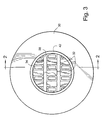
- FIGURE 2 is an end view of a stator bar and one of the stator bar clips 30.
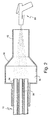
- FIGURE 3 is a cross-sectional side view of the end of the stator bar and its stator bar clip, schematically illustrating the powder coating process.
- strands are brazed to one another, as well as to the inside walls of the stator bar clip as schematically illustrated by braze material 38.
- a conventional high-temperature phosphorous copper braze alloy e.g., BCuP-1 or BCuP-5, may be applied to braze the strands to form the bar and to braze the end of the bar to the clip.
- a BCuP-5 braze alloy has a solidus temperature of 1190° Fahrenheit-F (643°Celcius-C), a liquidus temperature of 1475°F (802°C) and a brazing range of 1300°F to 1500°F (704°C to 816°C).
- a BCuP-1 braze alloy has a solidus temperature of 1310° Fahrenheit-F (710°Celcius-C), a liquidus temperature of 1688°F (920°C) and a brazing range of 1454°F to 1724°F (790°C to 940°C).
- the ends of the solid copper strands 32 are generally flush with a back wall of the expanded sub-chamber.
- the ends of the hollow copper strands 34 may extend about 10 to 500mils beyond the ends of solid strands 32 and into the sub-chamber 36, as in the illustrated embodiment.
- Powders for powder coating may be either thermoplastic powders which will re-melt on heating or thermosetting powders which do not re-melt on reheating. With thermosetting powders, during the curing process, a chemical cross-linking reaction is triggered at the curing temperature and reduces chemical reaction which gives the powder coating many of its desirable properties.
- Ultraviolet-curable powder coatings which are applied in the same manner as conventional powder coatings, offer some advantages including shorter cure time or lower cure temperature or both and are thus considered an appropriate alternative to conventional heat curing powders.
- suitable powder resins include epoxy powder resins, silicone powder, and silicone hybrid resin systems (silicone/epoxies and silicone/acrylics), examples of which are disclosed in U.S. Patent No. 6,778,053.
- the interior of the stator bar clip 30, including the corrosion susceptible braze joint between the clip 30 and the stator bar 16 is powder coated so that a thin barrier layer is deposited on the interior surface.
- the powder coat provides a corrosion resistant barrier to prevent water access to corrosion susceptible region(s) such as the clip-to-strand braze joints.
- the pre-requisite for any good coating is preparation.
- the preparation treatment will differ for various materials.
- the goal of the preparation is for oil, dirt and grease to be removed.
- a grounding strap is also connected to the frame of the machine and to the terminal connections.
- the powder is typically applied with an electrostatic spray gun to a part that is at earth, (or ground) potential.
- a thermoset epoxy powder containing various curing and flow control agents is spray coated onto the interior of the stator bar clip using an electrostatic spray coating system, such as a manual spray gun manufactured by the Nordson Corporation, Westlake, Ohio, under the trade name SureCoat®, which provides electrically charged powder coating material for spraying onto the grounded stator bar clip.
- an electrostatic spray coating system such as a manual spray gun manufactured by the Nordson Corporation, Westlake, Ohio, under the trade name SureCoat®, which provides electrically charged powder coating material for spraying onto the grounded stator bar clip.
- SureCoat® which provides electrically charged powder coating material for spraying onto the grounded stator bar clip.
- Other processes such as electrostatic tunnels may be used and, therefore, the invention is not limited to an electrostatic gun 50 as schematically illustrated.
- powder coating may be facilitated by isolating the target stator bar clip, including the braze joint between it and the stator bar, such as by partial disassembly to provide access to the end 42 of the clip 30 remote from the stator bar 16.
- the powder Before the powder is sent to the gun, it is fluidized to separate the individual grains of powder and so improve the electrostatic charge that can be applied to the powder and so that the powder flows more easily to the gun.
- the particles By grounding the clip and strands and directing the gun to spray the electrostatically charged epoxy particles into the clip, the particles will be attracted and adhere to the clip, strands, and braze joints therebetween. Additionally, the electrostatic charge affords sufficient attraction of the charged epoxy particles to the grounded structure that the powder will be drawn to all sides of the hollow strands and interior surfaces of the clip to provide a uniform film build-up.
- powder coating is not prone to air bubbles and voids that can be caused by human error during epoxy injection process.
- the powder coating is attracted to the copper surface of the bar and clip, with the exposed surface having a greater attraction than a previously coated area, thereby increasing the likelihood of a uniform coat.
- This electrostatic feature of the process enables effective material utilization and consistent finish characteristics. The powder will remain attached to the part as long as some of the electrostatic charge remains on the powder.
- a conventional electrostatic powder spray system has a hi-voltage, low amperage powder unit which supplies an electrode at the front of the gun 50 sufficient voltage to emit a field charge which is imparted to the powder material as it is propelled towards the interior surface of the stator bar clip/stator bar. Once charged, the particles are drawn to and attach themselves to the grounded structure.
- the voltage should be sufficiently high to provide a substantial deposition rate but not too high such that the electrostatic charge on the powder already deposited will tend to repel additional powder.
- the flow rate air pressure should be sufficiently high to afford an adequate deposition rate but not too high as to decrease the amount of electrostatic wrap.
- low atomizing air pressure will afford a better coverage than higher pressures.
- Powder coatings can be applied over a wide range of thicknesses. Typically, 25 micron is considered a minimum for mild interior applications up to 60 micron minimum for exterior applications. Preferably, the powder coating thickness should be from about 0.002 to about 0.050 inches thick, more preferably about 0.018 to about 0.020 inches thick, to provide adequate protection to act as a water barrier but not so thick as to cause cracking nor to clog the hollow strands.
- the powder coat is cured.
- the curing method depends upon the particular powder selected and may be by heating and/or by UV cure, for example. Curing the coating will occur in the field or in the factory. Field cure will be limited to repair and recondition work. Heating the powder coating in the field can be achieved with localized methods such as heat tapes or with local heaters. In the alternative, a UV curing powder coating may be used and UV cured in the field.
- the structure may be heated to a range of about 120° - 210°C over up to about two hours, depending on the composition of the powder coat, whereby the coating will flow and cure to provide a uniform barrier coating over the end of the stator bar, the braze joints and the interior of the clip, thereby to serve as a seal between the liquid coolant and the copper strands and brazing alloy applied to the strands, sealing potential leakage paths within the fitting.
- the structure may be preheated to approximately 100°C such that some melting or flowing of the solid epoxy powder occurs upon initial application of powder.
- a bore scope or other inspection instrument may be inserted into the chamber so that a technician may view the end of the stator bar and the coating material to confirm that the coating material is at the bottom of the sub-chamber and on the stator bar, and that the ends of the hollow strands extend up through the coating. This inspection may be accomplished when the coating material is initially applied to the fitting and/or after the coating material has been cured within the clip.
- a uniform barrier coating of, e.g., cured epoxy is provided, for example, as illustrated at 52 in FIG. 4, on the interior surface of the clip, including on the exposed ends of the strands and the braze material joining the strands to each other and to the clip.
- the powder because of its charge and by grounding the clip/strand, wraps around all surfaces to a substantially uniform thickness, as illustrated, prior to being cured. It will therefore be appreciated that, simply by spraying charged powder, the interior surface is completely and uniformly coated without clogging the hollow strands.
Landscapes
- Engineering & Computer Science (AREA)
- Power Engineering (AREA)
- Manufacturing & Machinery (AREA)
- Manufacture Of Motors, Generators (AREA)
- Insulation, Fastening Of Motor, Generator Windings (AREA)
Applications Claiming Priority (1)
| Application Number | Priority Date | Filing Date | Title |
|---|---|---|---|
| US10/983,673 US7150091B2 (en) | 2004-11-09 | 2004-11-09 | Powder coating for generator stator bar end fitting and method for applying the powder coating |
Publications (2)
| Publication Number | Publication Date |
|---|---|
| EP1655822A2 true EP1655822A2 (de) | 2006-05-10 |
| EP1655822A3 EP1655822A3 (de) | 2010-12-08 |
Family
ID=35478392
Family Applications (1)
| Application Number | Title | Priority Date | Filing Date |
|---|---|---|---|
| EP05256874A Withdrawn EP1655822A3 (de) | 2004-11-09 | 2005-11-07 | Pulverlackmaterial für Generatortandentwicklungsstabverbindungen und Verfahren zum Pulverbeschichten |
Country Status (5)
| Country | Link |
|---|---|
| US (2) | US7150091B2 (de) |
| EP (1) | EP1655822A3 (de) |
| JP (1) | JP2006230183A (de) |
| CN (1) | CN1835342A (de) |
| CA (1) | CA2525351A1 (de) |
Families Citing this family (18)
| Publication number | Priority date | Publication date | Assignee | Title |
|---|---|---|---|---|
| US20050227009A1 (en) * | 2004-04-13 | 2005-10-13 | Yu Wang | Epoxy spray lining for liquid-cooled generator stator bar clips |
| US7276134B2 (en) * | 2004-10-18 | 2007-10-02 | General Electric Company | Methods and systems for sealing liquid cooled stator bar end connections for a generator |
| US7150091B2 (en) * | 2004-11-09 | 2006-12-19 | General Electric Company | Powder coating for generator stator bar end fitting and method for applying the powder coating |
| US7705495B2 (en) * | 2006-11-17 | 2010-04-27 | Gm Global Technology Operations, Inc. | Cooling system for an electric motor |
| KR200445626Y1 (ko) | 2007-07-30 | 2009-08-19 | 두산중공업 주식회사 | 발전기 스테이터바의 에어플로우 검사용 지그 |
| US20090301645A1 (en) * | 2008-06-04 | 2009-12-10 | General Electric Company | System and method of joining components |
| US8268237B2 (en) * | 2009-01-08 | 2012-09-18 | General Electric Company | Method of coating with cryo-milled nano-grained particles |
| US8084902B2 (en) * | 2009-05-06 | 2011-12-27 | Hamilton Sundstrand Corporation | End plates for high speed generator applications |
| US8544769B2 (en) | 2011-07-26 | 2013-10-01 | General Electric Company | Multi-nozzle spray gun |
| US9162245B1 (en) * | 2012-03-29 | 2015-10-20 | BTD Wood Powder Coating, Inc. | Powder coating conveyor support |
| US9543814B2 (en) | 2014-01-07 | 2017-01-10 | Ge Aviation Systems Llc | Method of making a heat transfer element for an electric machine |
| US9509194B2 (en) | 2014-01-07 | 2016-11-29 | Ge Aviation Systems Llc | Generator assembly |
| EP2950424B1 (de) | 2014-05-26 | 2020-11-04 | General Electric Technology GmbH | Kammer für Leiter von elektrischen Maschinen |
| US9847702B2 (en) | 2015-06-08 | 2017-12-19 | General Electric Company | In-situ method for sealing fluid cooled conduits for a generator |
| CN106685121B (zh) * | 2017-01-16 | 2023-12-05 | 浙江博菲电气股份有限公司 | 用于立式水轮发电机定子线棒引线绝缘盒的柔性堵套及其装配方法 |
| JP7114513B2 (ja) * | 2019-03-11 | 2022-08-08 | 株式会社東芝 | 固定子巻線、発電機、および固定子巻線導体の接続方法 |
| DE102019203867A1 (de) * | 2019-03-21 | 2020-09-24 | Siemens Aktiengesellschaft | Maschinenkomponente mit Joch und Leiterwicklung |
| KR20220035592A (ko) * | 2020-09-14 | 2022-03-22 | 현대자동차주식회사 | 고정자 어셈블리의 제조 시스템 및 제조 방법 |
Family Cites Families (40)
| Publication number | Priority date | Publication date | Assignee | Title |
|---|---|---|---|---|
| US2462821A (en) * | 1945-01-22 | 1949-02-22 | Sk Wellman Co | Method of making composite articles |
| US3614493A (en) | 1970-01-29 | 1971-10-19 | Gen Electric | Universal liquid-cooled connection assembly |
| US3978359A (en) | 1974-10-30 | 1976-08-31 | Westinghouse Electric Corporation | Coil end insulation for dynamoelectric machines |
| JPS52110402A (en) | 1976-03-12 | 1977-09-16 | Hitachi Ltd | Liquid cooled winding for electric rotary machine |
| US4122870A (en) | 1976-12-08 | 1978-10-31 | Hines Vernon C | Protective bushing to enclose the end of a conduit liner |
| US4305792A (en) | 1977-12-21 | 1981-12-15 | Bristol Aerojet Limited | Processes for the electrodeposition of composite coatings |
| US4199700A (en) | 1978-07-31 | 1980-04-22 | Westinghouse Electric Corp. | Phase lead for connecting stator coils and parallel phase rings |
| JPS5851755A (ja) * | 1981-09-18 | 1983-03-26 | Mitsubishi Electric Corp | モ−ルド型水中モ−トル |
| JPS61121728A (ja) * | 1984-11-14 | 1986-06-09 | Fanuc Ltd | 液冷モ−タ |
| US4912831A (en) | 1987-01-09 | 1990-04-03 | Westinghouse Electric Corp. | Method for assembling bolted stator coils |
| US4806807A (en) | 1987-01-09 | 1989-02-21 | Westinghouse Electric Corp. | Method and apparatus for bolted series/phase generator connections |
| US4982122A (en) | 1988-05-23 | 1991-01-01 | Westinghouse Electric Corp. | Method and apparatus for insulating liquid-cooled stator coil headers and connectors |
| DK0504994T3 (da) | 1991-03-20 | 1997-07-07 | Gold Star Co | Rotor til en kapslet motor til en kapslet motorpumpe |
| JP2544692B2 (ja) * | 1992-04-21 | 1996-10-16 | ソマール株式会社 | 粉体塗装方法 |
| US5316801A (en) * | 1992-11-25 | 1994-05-31 | General Electric Company | Electrostatic powder coating method for insulating the series loop connections of a dynamoelectric machine |
| US5423473A (en) | 1994-05-09 | 1995-06-13 | Westinghouse Electric Corporation | Device for installing a header cap on a water header of a stator coil |
| DE19502308A1 (de) | 1995-01-26 | 1996-08-01 | Abb Management Ag | Verfahren zum Reparieren einer Anschlußvorrichtung für den Stromanschluß und zur Zuführung bzw. Abführung der Kühlflüssigkeit zu bzw. von den hohlen Teilleitern der Statorwicklungsstäbe elektrischer Maschinen |
| US5659944A (en) | 1995-01-26 | 1997-08-26 | Asea Brown Boveri Ag | Method for repairing a connecting device for the electrical connection and for supplying and carrying away the coolant to and from the hollow conductor elements of the stator winding bars of electrical machines |
| US5605590A (en) * | 1995-05-22 | 1997-02-25 | General Electric Co. | Methods for sealing liquid-cooled stator bar end connections for a generator |
| JP3051973B2 (ja) * | 1995-08-08 | 2000-06-12 | 進 武田 | 小型凹状電気部材用絶縁塗膜の形成方法 |
| US5581869A (en) * | 1995-08-15 | 1996-12-10 | General Electric Co. | Repair method for sealing liquid-cooled stator bar end fittings for a generator |
| US5796189A (en) * | 1996-01-23 | 1998-08-18 | General Electric Co. | Brazing procedure for generator liquid cooled stator bars |
| US5875539A (en) * | 1996-11-14 | 1999-03-02 | Siemens Westinghouse Power Corporation | Water-cooled stator coil end sealing process |
| KR100390890B1 (ko) | 1998-11-14 | 2003-10-08 | 주식회사 하이닉스반도체 | 도전층형성방법 |
| US6124659A (en) | 1999-08-20 | 2000-09-26 | Siemens Westinghouse Power Corporation | Stator wedge having abrasion-resistant edge and methods of forming same |
| JP2001200838A (ja) | 1999-11-09 | 2001-07-27 | Seiko Instruments Inc | 流体動圧軸受、流体動圧軸受装置、流体動圧軸受の製造方法、及び軸受表面加工方法 |
| US6778053B1 (en) * | 2000-04-19 | 2004-08-17 | General Electric Company | Powder coated generator field coils and related method |
| US6491208B2 (en) * | 2000-12-05 | 2002-12-10 | Siemens Westinghouse Power Corporation | Cold spray repair process |
| US7410674B2 (en) * | 2002-09-30 | 2008-08-12 | General Electric Company | Method of servicing an electro-dynamic apparatus |
| US6969932B2 (en) * | 2003-07-18 | 2005-11-29 | General Electric Co. | Application of corrosion protective coating for extending the lifetime of water cooled stator bar clips |
| EP1519389A1 (de) * | 2003-09-18 | 2005-03-30 | Rohm And Haas Company | Elektrisch isolerende Pulverbeschichtungen und Zusammensetzungen und Verfahren zu deren Herstellung |
| US7032808B2 (en) * | 2003-10-06 | 2006-04-25 | Outokumu Oyj | Thermal spray application of brazing material for manufacture of heat transfer devices |
| US6922001B2 (en) * | 2003-12-02 | 2005-07-26 | Visteon Global Technologies, Inc. | Process for assembling an alternator stator with clips that allows radial insertion of square wire with small slot openings |
| US20050227009A1 (en) * | 2004-04-13 | 2005-10-13 | Yu Wang | Epoxy spray lining for liquid-cooled generator stator bar clips |
| US7216796B2 (en) * | 2004-05-10 | 2007-05-15 | General Electric, Company | Crevice corrosion-resistant liquid-cooled armature bar clip-to-strand connection and related method |
| US7334316B2 (en) * | 2004-07-28 | 2008-02-26 | General Electric Company | Method of sealing a generator stator bar and a stator bar end fitting |
| US7276134B2 (en) * | 2004-10-18 | 2007-10-02 | General Electric Company | Methods and systems for sealing liquid cooled stator bar end connections for a generator |
| US20060091742A1 (en) | 2004-11-02 | 2006-05-04 | General Electric Company | Electroless metallic plating method for leak repair and prevention in liquid-cooled generator stator bars |
| US7150091B2 (en) * | 2004-11-09 | 2006-12-19 | General Electric Company | Powder coating for generator stator bar end fitting and method for applying the powder coating |
| US7166941B2 (en) | 2004-11-18 | 2007-01-23 | General Electric Company | Electroplated stator bar end and fitting |
-
2004
- 2004-11-09 US US10/983,673 patent/US7150091B2/en not_active Expired - Fee Related
-
2005
- 2005-11-02 JP JP2005319216A patent/JP2006230183A/ja active Pending
- 2005-11-03 CA CA002525351A patent/CA2525351A1/en not_active Abandoned
- 2005-11-07 EP EP05256874A patent/EP1655822A3/de not_active Withdrawn
- 2005-11-09 CN CN200510119497.XA patent/CN1835342A/zh active Pending
-
2006
- 2006-11-09 US US11/594,872 patent/US7417341B2/en not_active Expired - Fee Related
Also Published As
| Publication number | Publication date |
|---|---|
| US7417341B2 (en) | 2008-08-26 |
| CN1835342A (zh) | 2006-09-20 |
| US20070051779A1 (en) | 2007-03-08 |
| JP2006230183A (ja) | 2006-08-31 |
| US20060102702A1 (en) | 2006-05-18 |
| EP1655822A3 (de) | 2010-12-08 |
| CA2525351A1 (en) | 2006-05-09 |
| US7150091B2 (en) | 2006-12-19 |
Similar Documents
| Publication | Publication Date | Title |
|---|---|---|
| US7150091B2 (en) | Powder coating for generator stator bar end fitting and method for applying the powder coating | |
| US5605590A (en) | Methods for sealing liquid-cooled stator bar end connections for a generator | |
| US20150198389A1 (en) | Dual powder coating for aluminum heat exchangers | |
| US5316801A (en) | Electrostatic powder coating method for insulating the series loop connections of a dynamoelectric machine | |
| CA2454320C (en) | Pipe coating apparatus and method | |
| US7202579B2 (en) | Corrosion protective coating for extending the lifetime of water cooled stator bar clips | |
| EP2036616A1 (de) | Schlauch für eine Farbauftragungsvorrichtung und seine Verwendung | |
| US20080129127A1 (en) | Method of sealing a generator stator bar and a stator bar end fitting | |
| JP6882820B2 (ja) | 発電機用の流体冷却導管をシールするための原位置方法 | |
| US7166941B2 (en) | Electroplated stator bar end and fitting | |
| US20050257848A1 (en) | Plastic lined steel pipe with end corrosive protection core and method for producing same | |
| WO2008045403A2 (en) | Improved protective sleeve for pipe joint infill cladding | |
| US20050227009A1 (en) | Epoxy spray lining for liquid-cooled generator stator bar clips | |
| AU681513B2 (en) | Coating for tube bases and coolant tubes of heat exchangers | |
| CN100545497C (zh) | 管端带防蚀芯的树脂衬里钢管 | |
| JP7421392B2 (ja) | 粉体塗料を用いた塗装方法 | |
| CN209875425U (zh) | 压缩机以及制冷循环装置 | |
| JP2022151807A (ja) | 粉体塗装ノズル | |
| JP2017177458A (ja) | ポリオレフィン被覆鋼管の製造方法 | |
| JPS5836682A (ja) | ライニング施工方法 | |
| JP2001018325A (ja) | 樹脂被覆及びその製造方法、ならびに樹脂被覆の補完方法 | |
| JP3437732B2 (ja) | 水冷式電気機器 | |
| MXPA96000023A (en) | Coating for pipe plates, and cooling pipes in ac exchangers | |
| JPH09189395A (ja) | 埋設管継手部の防食被覆方法 | |
| KR19980059330U (ko) | 절연층이 형성된 후렌지형 볼 밸브 |
Legal Events
| Date | Code | Title | Description |
|---|---|---|---|
| PUAI | Public reference made under article 153(3) epc to a published international application that has entered the european phase |
Free format text: ORIGINAL CODE: 0009012 |
|
| AK | Designated contracting states |
Kind code of ref document: A2 Designated state(s): AT BE BG CH CY CZ DE DK EE ES FI FR GB GR HU IE IS IT LI LT LU LV MC NL PL PT RO SE SI SK TR |
|
| AX | Request for extension of the european patent |
Extension state: AL BA HR MK YU |
|
| PUAL | Search report despatched |
Free format text: ORIGINAL CODE: 0009013 |
|
| AK | Designated contracting states |
Kind code of ref document: A3 Designated state(s): AT BE BG CH CY CZ DE DK EE ES FI FR GB GR HU IE IS IT LI LT LU LV MC NL PL PT RO SE SI SK TR |
|
| AX | Request for extension of the european patent |
Extension state: AL BA HR MK YU |
|
| AKY | No designation fees paid | ||
| REG | Reference to a national code |
Ref country code: DE Ref legal event code: R108 |
|
| REG | Reference to a national code |
Ref country code: DE Ref legal event code: R108 Effective date: 20110822 |
|
| STAA | Information on the status of an ep patent application or granted ep patent |
Free format text: STATUS: THE APPLICATION IS DEEMED TO BE WITHDRAWN |
|
| 18D | Application deemed to be withdrawn |
Effective date: 20110609 |