EP1655470A1 - Dispositif et procédé d'estimation en temps réel de l'angle de début de combustion d'un moteur à combustion interne - Google Patents
Dispositif et procédé d'estimation en temps réel de l'angle de début de combustion d'un moteur à combustion interne Download PDFInfo
- Publication number
- EP1655470A1 EP1655470A1 EP05300848A EP05300848A EP1655470A1 EP 1655470 A1 EP1655470 A1 EP 1655470A1 EP 05300848 A EP05300848 A EP 05300848A EP 05300848 A EP05300848 A EP 05300848A EP 1655470 A1 EP1655470 A1 EP 1655470A1
- Authority
- EP
- European Patent Office
- Prior art keywords
- signal
- combustion
- stage
- derivative
- analog
- Prior art date
- Legal status (The legal status is an assumption and is not a legal conclusion. Google has not performed a legal analysis and makes no representation as to the accuracy of the status listed.)
- Granted
Links
Images



Classifications
-
- F—MECHANICAL ENGINEERING; LIGHTING; HEATING; WEAPONS; BLASTING
- F02—COMBUSTION ENGINES; HOT-GAS OR COMBUSTION-PRODUCT ENGINE PLANTS
- F02D—CONTROLLING COMBUSTION ENGINES
- F02D35/00—Controlling engines, dependent on conditions exterior or interior to engines, not otherwise provided for
- F02D35/02—Controlling engines, dependent on conditions exterior or interior to engines, not otherwise provided for on interior conditions
- F02D35/028—Controlling engines, dependent on conditions exterior or interior to engines, not otherwise provided for on interior conditions by determining the combustion timing or phasing
-
- F—MECHANICAL ENGINEERING; LIGHTING; HEATING; WEAPONS; BLASTING
- F02—COMBUSTION ENGINES; HOT-GAS OR COMBUSTION-PRODUCT ENGINE PLANTS
- F02D—CONTROLLING COMBUSTION ENGINES
- F02D35/00—Controlling engines, dependent on conditions exterior or interior to engines, not otherwise provided for
- F02D35/02—Controlling engines, dependent on conditions exterior or interior to engines, not otherwise provided for on interior conditions
- F02D35/023—Controlling engines, dependent on conditions exterior or interior to engines, not otherwise provided for on interior conditions by determining the cylinder pressure
-
- F—MECHANICAL ENGINEERING; LIGHTING; HEATING; WEAPONS; BLASTING
- F02—COMBUSTION ENGINES; HOT-GAS OR COMBUSTION-PRODUCT ENGINE PLANTS
- F02D—CONTROLLING COMBUSTION ENGINES
- F02D41/00—Electrical control of supply of combustible mixture or its constituents
- F02D41/24—Electrical control of supply of combustible mixture or its constituents characterised by the use of digital means
- F02D41/26—Electrical control of supply of combustible mixture or its constituents characterised by the use of digital means using computer, e.g. microprocessor
- F02D41/266—Electrical control of supply of combustible mixture or its constituents characterised by the use of digital means using computer, e.g. microprocessor the computer being backed-up or assisted by another circuit, e.g. analogue
-
- F—MECHANICAL ENGINEERING; LIGHTING; HEATING; WEAPONS; BLASTING
- F02—COMBUSTION ENGINES; HOT-GAS OR COMBUSTION-PRODUCT ENGINE PLANTS
- F02D—CONTROLLING COMBUSTION ENGINES
- F02D41/00—Electrical control of supply of combustible mixture or its constituents
- F02D41/24—Electrical control of supply of combustible mixture or its constituents characterised by the use of digital means
- F02D41/26—Electrical control of supply of combustible mixture or its constituents characterised by the use of digital means using computer, e.g. microprocessor
- F02D41/28—Interface circuits
-
- G—PHYSICS
- G01—MEASURING; TESTING
- G01M—TESTING STATIC OR DYNAMIC BALANCE OF MACHINES OR STRUCTURES; TESTING OF STRUCTURES OR APPARATUS, NOT OTHERWISE PROVIDED FOR
- G01M15/00—Testing of engines
- G01M15/04—Testing internal-combustion engines
- G01M15/08—Testing internal-combustion engines by monitoring pressure in cylinders
-
- F—MECHANICAL ENGINEERING; LIGHTING; HEATING; WEAPONS; BLASTING
- F02—COMBUSTION ENGINES; HOT-GAS OR COMBUSTION-PRODUCT ENGINE PLANTS
- F02D—CONTROLLING COMBUSTION ENGINES
- F02D41/00—Electrical control of supply of combustible mixture or its constituents
- F02D41/24—Electrical control of supply of combustible mixture or its constituents characterised by the use of digital means
- F02D41/26—Electrical control of supply of combustible mixture or its constituents characterised by the use of digital means using computer, e.g. microprocessor
- F02D41/28—Interface circuits
- F02D2041/281—Interface circuits between sensors and control unit
- F02D2041/285—Interface circuits between sensors and control unit the sensor having a signal processing unit external to the engine control unit
-
- F—MECHANICAL ENGINEERING; LIGHTING; HEATING; WEAPONS; BLASTING
- F02—COMBUSTION ENGINES; HOT-GAS OR COMBUSTION-PRODUCT ENGINE PLANTS
- F02D—CONTROLLING COMBUSTION ENGINES
- F02D2250/00—Engine control related to specific problems or objectives
- F02D2250/12—Timing of calculation, i.e. specific timing aspects when calculation or updating of engine parameter is performed
Definitions
- the invention relates to rotary engines with internal combustion (gasoline or diesel) with direct or indirect fuel injection, and more particularly the estimation of the start of combustion in such an engine.
- U.S. Patent No. 4,567,751 discloses a knock detection device in a diesel engine utilizing a rate of change of the combustion pressure.
- the invention aims to provide a radically different solution to estimate the angle of the start of combustion of a gasoline or diesel engine.
- an analog device for real-time estimation of the combustion start angle of an engine comprising an input for receiving a cylinder pressure signal and a circuit analog estimation device capable of delivering a signal representative of the start times of combustion, from a signal representative of the time derivative of the cylinder pressure signal.
- the signal representative of the instants of start of combustion is advantageously a periodic logic signal of period equal to the thermodynamic cycle.
- the analog estimation circuit comprises a divider stage connected to said input and deriving said derivative signal.
- the circuit also comprises analog processing means capable of detecting the peaks of a high frequency signal derived from the derivative signal.
- the first peak indicates the start time of combustion.
- These analog processing means advantageously comprise a band-pass filtering stage connected to the differentiator stage for delivering said high-frequency signal, an amplifier stage connected to the output of the filtering stage, and a peak detection stage connected to the output of the amplifier stage.
- the analog processing means may advantageously comprise a comparison stage with two thresholds, connected to the output of the peak detector, for outputting the periodic logic signal representative of the start times of combustion.
- a method for real-time estimation of the angle of start of combustion of an engine comprising an elaboration from a signal representative of the time derivative of a cylinder pressure signal, of a signal representative of the combustion instants.
- This development advantageously comprises a detection of the peaks of a high frequency signal derived from the derivative signal.
- said development comprises a band-pass filtering of the derivative signal for delivering said high frequency signal, an amplification of the filtered signal and a detection of the peaks of the amplified signal.
- the signal representative of the combustion start time is a periodic signal of period equal to the thermodynamic cycle; said elaboration advantageously comprises a comparison with two thresholds of the peak signal, so as to deliver said periodic signal.
- FIG. 1 diagrammatically shows in section a motor cylinder equipped with a connecting rod 7, with a piston 6 defining, with the upper part of the cylinder, a combustion chamber 4.
- This combustion chamber communicates with an intake zone 3, an exhaust zone 2.
- an injector or a candle 1 also opens into this combustion chamber.
- a crank angle sensor 9 delivers information to an electronic engine control unit 8.
- a cylinder pressure sensor 5 connected to an analog circuit 10 for estimating the start of combustion angle (SOC).
- This analog estimation circuit 10 has its output connected to the electronic control unit 8.
- the analog circuit 10 comprises an input terminal ES connected to the pressure sensor and intended to receive a voltage representative of the pressure in the combustion chamber of the cylinder.
- the circuit 10 comprises at the head a derivative stage ETD conventionally formed here of an integrator whose gain is regulated by the product RC.
- the output voltage of the stage ETD is proportional (in the ratio of proportionality RC) to the time derivative of the input voltage, that is to say to the time derivative of the cylinder pressure signal.
- the ETD derivative stage is followed in this embodiment by a bandpass filtering stage FLT which performs a filtering of the pressure derivative to extract a high frequency signal, for example at 10 kHz, which appears at the time of transmission. combustion.
- This band-pass filtering stage is advantageously followed by an amplifier stage AMP which amplifies the signal emanating from the filter FLT.
- the gain of this amplifier is given by the ratio - R5 / R4.
- the AMP amplifier step is followed by a DTC comparator whose assembly comprises two parts, namely a first portion forming a peak detector and composed of the diode D1, the capacitor C3 and the resistor R7.
- the second part of the assembly consists of the amplifier Q3 mounted as a follower and which allows an impedance matching making the operation of the peak detector independent of the load generated by the use.
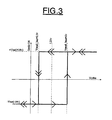
- the last element of the analog circuit 10, in this embodiment, is a two-threshold comparator CMP of non-inverting trigger type whose characteristic is illustrated in FIG.
- the high threshold is chosen equal to 0.5V while the low threshold is chosen equal to 2V.
- the low threshold is substantially equal to 1.25 + Vsat * R8 / R9 while the threshold high is substantially equal to 1.25 - Vsat * R8 / R9.
- the adaptation is used with the transistor Q1 by means of a switching type circuit.
- FIG. 4 summarizes the main steps of an embodiment of the invention, and also summarizes the operation of the embodiment of the device illustrated in FIG. 2.
- step 41 the high frequencies of the derivative signal of pressure. This extraction can be performed for example by the filter stage SLT.
- step 42 the signal from the filter 41 is amplified.
- the next step 43 is the peak detection of the amplified signal. This step makes it possible to transform a high-frequency signal into a frequency-based signal that will make it possible to detect the presence of high frequencies.
- the peak detector aims to memorize the transition from a low voltage to a higher voltage.
- the last step 44 is a comparison of these peaks with respect to two thresholds. Specifically, a 0V-5V pulse signal is generated when the peaks of the 10 kHz portion of the pressure derivative have been detected by peak detection 43.
- the invention estimates in real time the start of combustion in diesel or gasoline engines. It is based on the cylinder pressure derivative signal and the corresponding device is placed between the cylinder pressure sensor and the engine control electronics.
- the device generates from the pressure derivative signal a pulse signal between 0V and 5V of period equal to the thermodynamic cycle.
- the rising edges of this signal correspond to the successive instants of start of combustion.
Landscapes
- Engineering & Computer Science (AREA)
- Chemical & Material Sciences (AREA)
- Combustion & Propulsion (AREA)
- General Engineering & Computer Science (AREA)
- Mechanical Engineering (AREA)
- Computer Hardware Design (AREA)
- Microelectronics & Electronic Packaging (AREA)
- Physics & Mathematics (AREA)
- General Physics & Mathematics (AREA)
- Combined Controls Of Internal Combustion Engines (AREA)
Abstract
Description
- L'invention concerne les moteurs rotatifs à combustion interne (essence ou diesel) à injection directe ou indirecte de carburant, et plus particulièrement l'estimation du début de combustion dans un tel moteur.
- Les normes européennes anti-pollution deviennent de plus en plus sévères sur les moteurs d'automobiles. Il est important pour les constructeurs automobiles de réduire les émissions polluantes de leurs moteurs sans négliger leur consommation en carburant et leur performance. Or, la phase prépondérante du cycle 4 temps sur ces émissions est la phase de combustion. Il est donc important de bien connaître cette phase et ses caractéristiques.
- L'une de ces caractéristiques est l'instant au début de la combustion. Il s'agit d'un paramètre important influant sur le rendement du cycle thermodynamique, et donc sur le couple. Ce paramètre agit aussi sur le rendement de combustion.
- Actuellement, le début de combustion est rarement estimé en ligne sur un moteur implanté dans un véhicule. Lorsque cette détection est effectuée, elle l'est en utilisant des méthodes numériques basées sur des principes thermodynamiques ou de traitement numérique du signal. La demande de brevet américain n°2003/145829 illustre de telles méthodes numériques. Or, ces méthodes, gourmandes en temps de calcul, sont difficilement implantables sur les calculateurs de contrôle moteur actuels.
- Il a également été envisagé de détecter le début de combustion à l'aide d'un accéléromètre, comme décrit par exemple dans la demande de brevet européen n°1 092 968
- Le brevet américain n° 4 567 751 décrit un dispositif de détection de cognement dans un moteur diesel utilisant une vitesse de changement de la pression de combustion.
- L'invention vise à apporter une solution radicalement différente pour estimer l'angle du début de combustion d'un moteur essence ou diesel.
- Ainsi, selon un mode de mise en oeuvre de l'invention, il est proposé d'estimer en temps réel le début de combustion dans les voitures diesel ou essence en se basant sur le signal de dérivé de pression cylindre.
- Selon un mode de réalisation de l'invention, il est proposé un dispositif analogique d'estimation en temps réel de l'angle de début de combustion d'un moteur, ce dispositif comprenant une entrée pour recevoir un signal de pression cylindre et un circuit analogique d'estimation apte à délivrer un signal représentatif des instants de début de combustion, à partir d'un signal représentatif de la dérivée temporelle du signal de pression cylindre.
- Le signal représentatif des instants de début de combustion est avantageusement un signal logique périodique de période égale au cycle thermodynamique.
- Selon un mode de réalisation de l'invention, le circuit analogique d'estimation comporte un étage dérivateur relié à ladite entrée et dérivant ledit signal de dérivée. Le circuit comporte également des moyens analogiques de traitement aptes à détecter les crêtes d'un signal haute fréquence issu du signal de dérivée.
- La première crête indique l'instant de début de combustion.
- Ces moyens analogiques de traitement comportent avantageusement un étage de filtrage passe-bande relié à l'étage dérivateur pour délivrer ledit signal haute fréquence, un étage amplificateur relié à la sortie de l'étage de filtrage, et un étage de détection de crêtes relié à la sortie de l'étage amplificateur.
- Les moyens analogiques de traitement peuvent comporter avantageusement un étage de comparaison à deux seuils, relié à la sortie du détecteur de crêtes, pour délivrer le signal logique périodique représentatif des instants de début de combustion.
- Selon un mode de mise en oeuvre de l'invention, il est également proposé un procédé d'estimation en temps réel de l'angle de début de combustion d'un moteur, comprenant une élaboration à partir d'un signal représentatif de la dérivée temporelle d'un signal de pression cylindre, d'un signal représentatif des instants de combustion.
- Cette élaboration comporte avantageusement une détection des crêtes d'un signal haute fréquence issu du signal de dérivée.
- Selon un mode de mise en oeuvre, ladite élaboration comporte un filtrage passe-bande du signal de dérivée pour délivrer ledit signal haute fréquence, une amplification du signal filtré et une détection des crêtes du signal amplifié.
- Le signal représentatif de l'instant de début de combustion est un signal périodique de période égale au cycle thermodynamique ; ladite élaboration comporte avantageusement une comparaison à deux seuils du signal de crête, de façon à délivrer ledit signal périodique.
- D'autres avantages et caractéristiques de l'invention apparaîtront à l'examen de la description détaillée de mode de mise en oeuvre et de réalisation, nullement limitatifs et des dessins annexés sur lesquels :
- La figure 1 illustre schématiquement une partie d'un moteur à combustion interne équipé d'un dispositif selon un mode de réalisation de l'invention,
- La figure 2 illustre plus en détail un mode de réalisation d'un dispositif selon l'invention,
- La figure 3 illustre un exemple de caractéristique d'un comparateur à deux seuils incorporé dans un dispositif selon un mode de réalisation de l'invention, et,
- La figure 4 illustre schématiquement les principales étapes d'un mode de mise en oeuvre du procédé selon l'invention.
- Sur la figure 1, on a représenté schématiquement en coupe un cylindre moteur équipé d'une bielle 7, d'un piston 6 définissant, avec la partie supérieure du cylindre, une chambre de combustion 4.
- Cette chambre de combustion communique avec une zone d'admission 3, une zone d'échappement 2. Par ailleurs, un injecteur ou une bougie 1 débouche également dans cette chambre de combustion.
- Un capteur d'angle vilebrequin 9 délivre des informations à un boîtier électronique de contrôle moteur 8.
- Par ailleurs, selon un mode de réalisation de l'invention, il est prévu un capteur de pression cylindre 5 relié à un circuit analogique 10 d'estimation de l'angle de début de combustion (SOC). Ce circuit analogique d'estimation 10 a sa sortie reliée au boîtier électronique de contrôle 8.
- Comme illustré sur la figure 2, le circuit analogique 10 comporte une borne d'entrée ES reliée au capteur de pression et destinée à recevoir une tension représentative de la pression dans la chambre de combustion du cylindre.
- Le circuit 10 comporte en tête un étage dérivateur ETD formé ici classiquement d'un intégrateur dont le gain est réglé par le produit RC. La tension de sortie de l'étage ETD est proportionnelle (dans le rapport de proportionnalité RC) à la dérivée temporelle de la tension d'entrée, c'est-à-dire à la dérivée temporelle du signal de pression cylindre.
- L'étage dérivateur ETD est suivi dans ce mode de réalisation, d'un étage de filtrage passe-bande FLT qui effectue un filtrage de la dérivée de pression pour en extraire un signal haute fréquence, par exemple à 10khz, qui apparaît au moment de la combustion. La fonction de transfert de ce filtre passe-bande est par exemple la suivante :

- Cet étage de filtrage passe-bande est suivi avantageusement d'un étage amplificateur AMP qui amplifie le signal émanant du filtre FLT. Le gain de cet amplificateur est donné par le rapport - R5/R4.
- L'étape amplificateur AMP est suivie d'un comparateur DTC dont le montage comporte deux parties, à savoir une première partie formant un détecteur de crêtes et composée de la diode D1, du condensateur C3 et de la résistance R7.
- La deuxième partie du montage est composée de l'amplificateur Q3 monté en suiveur et qui permet de réaliser une adaptation d'impédance rendant le fonctionnement du détecteur de crêtes indépendant de la charge engendrée par l'utilisation.
- En fonctionnement, lorsque la tension Outl à l'entrée du détecteur de crêtes est supérieure à la somme de la tension aux bornes du condensateur C3 et de la tension de seuil de la diode D1, alors la tension aux bornes du condensateur C3 est égale à la différence entre la tension Outl et la tension de seuil de la diode.
- Par contre, lorsque la tension Outl est inférieure à la somme de la tension aux bornes du condensateur C3 et de la tension de seuil de la diode, alors la diode se bloque et le condensateur C3 se décharge à travers la résistance R7 avec une constante de temps égale à C3*R7.
- Le dernier élément du circuit analogique 10, dans ce mode de réalisation, est un comparateur à deux seuils CMP de type déclencheur (trigger) non-inverseur dont la caractéristique est illustrée sur la figure 3.
- Le seuil haut est choisi égal à 0,5V tandis que le seuil bas est choisi égal à 2V.
- Si l'on considère que la résistance R9 est très grande devant la résistance R8 (par exemple R9 = 2 kΩ et R8 = 100 Ω) alors le seuil bas est sensiblement égal à 1,25 + Vsat*R8/R9 tandis que le seuil haut est sensiblement égal à 1,25 - Vsat*R8/R9.
- L'adaptation est utilisée avec le transistor Q1 à l'aide d'un montage de type commutation.
- La figure 4 résume les principales étapes d'un mode de mise en oeuvre de l'invention, et résume également le fonctionnement du mode de réalisation du dispositif illustré sur la figure 2.
- Après une étape 40 de dérivée du signal de pression cylindre, on extrait dans l'étape 41 les hautes fréquences du signal de dérivée de pression. Cette extraction peut être effectuée par exemple par l'étage de filtrage SLT.
- Puis, dans l'étape 42, on amplifie le signal issu du filtrage 41.
- L'étape suivante 43 est la détection des crêtes du signal amplifié. Cette étape permet de transformer un signal haute fréquence en un signal base fréquence qui va permettre de détecter la présence de hautes fréquences.Le détecteur de crêtes a pour but de mémoriser le passage d'une tension faible à une tension plus importante.
- Enfin, la dernière étape 44 est une comparaison de ces crêtes par rapport à deux seuils. Plus précisément, on génère un signal créneau 0V-5V lorsque les crêtes de la partie du signal à 10khz de la dérivée de pression ont été détectées par la détection de crête 43.
- Ainsi, l'invention estime en temps réel le début de combustion dans les moteurs diesel ou essence. Elle est basée sur le signal de dérivée de pression de cylindre et le dispositif correspondant est placé entre le capteur de pression de cylindre et le boîtier électronique de contrôle moteur.
- Le dispositif selon un mode de réalisation de l'invention génère à partir du signal de dérivée de pression un signal créneau entre 0V et 5Vde période égale au cycle thermodynamique. Les fronts montants de ce signal correspondent aux instants successifs de début de combustion.
Claims (10)
- Dispositif analogique d'estimation en temps réel de l'angle de début de combustion d'un moteur, comprenant une entrée pour recevoir un signal de pression cylindre et un circuit analogique d'estimation (10) apte à délivrer un signal représentatif des instants de début de combustion, à partir d'un signal représentatif de la dérivée temporelle du signal de pression cylindre.
- Dispositif selon la revendication 1, caractérisé par le fait que le signal représentatif des instants de début de combustion est un signal logique périodique de période égale au cycle thermodynamique.
- Dispositif selon la revendication 1 ou 2, caractérisé par le fait que le circuit analogique d'estimation comporte un étage dérivateur (ETD) relié à ladite entrée et délivrant ledit signal de dérivée, et des moyens analogiques de traitement aptes à détecter les crêtes d'un signal haute fréquence issu du signal de dérivée.
- Dispositif selon la revendication 3, caractérisé par le fait que les moyens analogiques de traitement comportent un étage de filtrage passe-bande (FLT) relié à l'étage dérivateur pour délivrer ledit signal haute fréquence, un étage amplificateur (AMP) relié à la sortie de l'étage de filtrage, et un étage de détection de crêtes (DTC) relié à la sortie de l'étage amplificateur.
- Dispositif selon les revendications 2 et 4, caractérisé par le fait que les moyens analogiques de traitement comportent un étage de comparaison à deux seuils (CMP) relié à la sortie du détecteur de crêtes, pour délivrer ledit signal logique.
- Procédé d'estimation en temps réel de l'angle de début de combustion d'un moteur, comprenant une élaboration (40-44) à partir d'un signal représentatif de la dérivée temporelle d'un signal de pression cylindre, d'un signal représentatif des instants de début de combustion.
- Procédé selon la revendication 6, caractérisé par le fait que le signal représentatif des instants de début de combustion est un signal logique périodique de période égale au cycle thermodynamique.
- Procédé selon la revendication 6 ou 7, caractérisé par le fait que ladite élaboration comporte une détection des crêtes d'un signal haute fréquence issu du signal de dérivée.
- Procédé selon la revendication 8, caractérisé par le fait que ladite élaboration comporte un filtrage passe-bande (41) du signal de dérivée pour délivrer ledit signal haute fréquence, une amplification du signal filtré (42), et une détection des crêtes (43) du signal amplifié.
- Procédé selon les revendications 7 et 9, caractérisé par le fait que ladite élaboration comporte une comparaison à deux seuils (44) du signal de crêtes, de façon à délivrer ledit signal logique.
Applications Claiming Priority (1)
| Application Number | Priority Date | Filing Date | Title |
|---|---|---|---|
| FR0411936A FR2877696B1 (fr) | 2004-11-09 | 2004-11-09 | Dispositif et procede d'estimation en temps reel de l'angle de debut de combustion d'un moteur a combustion interne |
Publications (2)
| Publication Number | Publication Date |
|---|---|
| EP1655470A1 true EP1655470A1 (fr) | 2006-05-10 |
| EP1655470B1 EP1655470B1 (fr) | 2015-07-01 |
Family
ID=34953090
Family Applications (1)
| Application Number | Title | Priority Date | Filing Date |
|---|---|---|---|
| EP05300848.8A Expired - Lifetime EP1655470B1 (fr) | 2004-11-09 | 2005-10-24 | Dispositif et procédé d'estimation en temps réel de l'angle de début de combustion d'un moteur à combustion interne |
Country Status (2)
| Country | Link |
|---|---|
| EP (1) | EP1655470B1 (fr) |
| FR (1) | FR2877696B1 (fr) |
Citations (6)
| Publication number | Priority date | Publication date | Assignee | Title |
|---|---|---|---|---|
| US4406265A (en) * | 1982-03-26 | 1983-09-27 | General Motors Corporation | Peak combustion pressure controlled spark timing control system with engine speed dependent filter |
| US4567751A (en) * | 1982-10-07 | 1986-02-04 | Nippon Soken, Inc. | Knocking detection device in diesel engine |
| US4928653A (en) * | 1988-04-19 | 1990-05-29 | Mitsubishi Denki Kabushiki Kaisha | Air-fuel ratio control device for an internal combustion engine |
| US4936137A (en) * | 1988-03-08 | 1990-06-26 | Mitsubishi Denki K.K. | Pressure detecting apparatus |
| US5642713A (en) * | 1994-02-01 | 1997-07-01 | Fev Motorentechnik Gmbh & Co. Kommanditgesellschaft | Process for controlling a piston internal combustion engine by maintaining the running limit |
| US20030010101A1 (en) * | 2001-07-11 | 2003-01-16 | Zur Loye Axel O. | Apparatus and methods for determining start of combustion for an internal combustion engine |
Family Cites Families (2)
| Publication number | Priority date | Publication date | Assignee | Title |
|---|---|---|---|---|
| US4432987A (en) | 1982-04-23 | 1984-02-21 | Pfizer Inc. | Crystalline benzenesulfonate salts of sultamicillin |
| US6766497B2 (en) | 2002-01-25 | 2004-07-20 | Hewlett-Packard Development Company, L.P. | Method and system for reproduction in a genetic optimization process |
-
2004
- 2004-11-09 FR FR0411936A patent/FR2877696B1/fr not_active Expired - Fee Related
-
2005
- 2005-10-24 EP EP05300848.8A patent/EP1655470B1/fr not_active Expired - Lifetime
Patent Citations (6)
| Publication number | Priority date | Publication date | Assignee | Title |
|---|---|---|---|---|
| US4406265A (en) * | 1982-03-26 | 1983-09-27 | General Motors Corporation | Peak combustion pressure controlled spark timing control system with engine speed dependent filter |
| US4567751A (en) * | 1982-10-07 | 1986-02-04 | Nippon Soken, Inc. | Knocking detection device in diesel engine |
| US4936137A (en) * | 1988-03-08 | 1990-06-26 | Mitsubishi Denki K.K. | Pressure detecting apparatus |
| US4928653A (en) * | 1988-04-19 | 1990-05-29 | Mitsubishi Denki Kabushiki Kaisha | Air-fuel ratio control device for an internal combustion engine |
| US5642713A (en) * | 1994-02-01 | 1997-07-01 | Fev Motorentechnik Gmbh & Co. Kommanditgesellschaft | Process for controlling a piston internal combustion engine by maintaining the running limit |
| US20030010101A1 (en) * | 2001-07-11 | 2003-01-16 | Zur Loye Axel O. | Apparatus and methods for determining start of combustion for an internal combustion engine |
Also Published As
| Publication number | Publication date |
|---|---|
| FR2877696B1 (fr) | 2009-09-18 |
| FR2877696A1 (fr) | 2006-05-12 |
| EP1655470B1 (fr) | 2015-07-01 |
Similar Documents
| Publication | Publication Date | Title |
|---|---|---|
| JP4409376B2 (ja) | 内燃機関の制御装置 | |
| EP1141537A1 (fr) | Detection de l'encrassement d'un filtre a carburant d'un circuit d'alimentation d'un moteur a combustion interne | |
| EP1242723B1 (fr) | Procede de diagnostic d'un systeme d'echappement de moteur a combustion | |
| FR2903142A1 (fr) | Procede de diagnostic d'un filtre a particules et dispositif pour sa mise en oeuvre | |
| EP1769153B1 (fr) | Systeme de controle du fonctionnement d'un moteur diesel de vehicule automobile associe a un catalyseur d'oxydation | |
| FR2829798A1 (fr) | Procede de gestion du fonctionnement d'un filtre a particules revetu d'une phase catalytique pour moteur a combustion | |
| WO1999006685A1 (fr) | Procede de correction des a-coups de couple d'un moteur a combustion interne | |
| EP2619426B1 (fr) | Procede d'estimation adaptative d'une charge courante en suie d'un filtre a particules | |
| FR2467396A1 (fr) | Detecteur de cliquetis pour un moteur a combustion interne | |
| EP1655470B1 (fr) | Dispositif et procédé d'estimation en temps réel de l'angle de début de combustion d'un moteur à combustion interne | |
| FR3110200A1 (fr) | Dispositif et procédé de détection d'une défaillance d'un moteur à combustion interne pour véhicule automobile | |
| EP1499803A1 (fr) | MOTEUR DIESEL COMPORTANT UN DISPOSITIF DE CONTROLE DU DEBIT D'INJECTION DE CARBURANT | |
| FR2797952A1 (fr) | Dispositif de detection de cognement pour un moteur a combustion interne | |
| EP1759109A1 (fr) | Systeme d'aide a la regeneration de moyens de depollution pour moteur de vehicule automobile | |
| EP1607605B1 (fr) | Système d'estimation de la pression dans le collecteur d'échappement d'un moteur diesel et procédé de calibrage de ce système | |
| EP3482052B1 (fr) | Procede d'adaptation d'une estimation d'une vitesse de combustion des suies d'un filtre a particules de moteur thermique | |
| FR2904660A1 (fr) | Determination d'un debut de combustion dans un moteur a combustion interne | |
| EP1920144A2 (fr) | Dispositif pour la detection en temps reel du commencement de la phase de combustion et procede correspondant | |
| EP2150795B1 (fr) | Procede de calibrage de l'offset d'un signal issu d'un capteur de pression dans une chambre de combustion | |
| FR2880656A1 (fr) | Procede de gestion d'un moteur a combustion interne notamment d'un moteur diesel et installation pour sa mise en oeuvre | |
| FR3073428B1 (fr) | Procede d’adaptation de l’additivation aux emissions pour aide a la regeneration d’un filtre a particules | |
| EP2123889A1 (fr) | Procédé de commande pour moteur à injection et dispositif pour mettre en oeuvre ledit procédé | |
| FR2991002A1 (fr) | Procede et dispositif de commande de la combustion d'un moteur a allumage commande en regime transitoire | |
| EP1963648A1 (fr) | Procede de commande d'un moteur permettant une amelioration d'un diagnostic de combustion du moteur | |
| FR2851654A1 (fr) | Procede de detection de cliquetis |
Legal Events
| Date | Code | Title | Description |
|---|---|---|---|
| PUAI | Public reference made under article 153(3) epc to a published international application that has entered the european phase |
Free format text: ORIGINAL CODE: 0009012 |
|
| AK | Designated contracting states |
Kind code of ref document: A1 Designated state(s): AT BE BG CH CY CZ DE DK EE ES FI FR GB GR HU IE IS IT LI LT LU LV MC NL PL PT RO SE SI SK TR |
|
| AX | Request for extension of the european patent |
Extension state: AL BA HR MK YU |
|
| 17P | Request for examination filed |
Effective date: 20060925 |
|
| 17Q | First examination report despatched |
Effective date: 20061115 |
|
| AKX | Designation fees paid |
Designated state(s): AT BE BG CH CY CZ DE DK EE ES FI FR GB GR HU IE IS IT LI LT LU LV MC NL PL PT RO SE SI SK TR |
|
| GRAP | Despatch of communication of intention to grant a patent |
Free format text: ORIGINAL CODE: EPIDOSNIGR1 |
|
| INTG | Intention to grant announced |
Effective date: 20150108 |
|
| GRAS | Grant fee paid |
Free format text: ORIGINAL CODE: EPIDOSNIGR3 |
|
| GRAA | (expected) grant |
Free format text: ORIGINAL CODE: 0009210 |
|
| RAP1 | Party data changed (applicant data changed or rights of an application transferred) |
Owner name: RENAULT S.A.S. |
|
| AK | Designated contracting states |
Kind code of ref document: B1 Designated state(s): AT BE BG CH CY CZ DE DK EE ES FI FR GB GR HU IE IS IT LI LT LU LV MC NL PL PT RO SE SI SK TR |
|
| REG | Reference to a national code |
Ref country code: GB Ref legal event code: FG4D Free format text: NOT ENGLISH |
|
| REG | Reference to a national code |
Ref country code: AT Ref legal event code: REF Ref document number: 734099 Country of ref document: AT Kind code of ref document: T Effective date: 20150715 Ref country code: CH Ref legal event code: EP |
|
| REG | Reference to a national code |
Ref country code: IE Ref legal event code: FG4D Free format text: LANGUAGE OF EP DOCUMENT: FRENCH |
|
| REG | Reference to a national code |
Ref country code: DE Ref legal event code: R096 Ref document number: 602005046849 Country of ref document: DE |
|
| REG | Reference to a national code |
Ref country code: FR Ref legal event code: PLFP Year of fee payment: 11 |
|
| REG | Reference to a national code |
Ref country code: AT Ref legal event code: MK05 Ref document number: 734099 Country of ref document: AT Kind code of ref document: T Effective date: 20150701 |
|
| REG | Reference to a national code |
Ref country code: NL Ref legal event code: MP Effective date: 20150701 |
|
| REG | Reference to a national code |
Ref country code: LT Ref legal event code: MG4D |
|
| PG25 | Lapsed in a contracting state [announced via postgrant information from national office to epo] |
Ref country code: LV Free format text: LAPSE BECAUSE OF FAILURE TO SUBMIT A TRANSLATION OF THE DESCRIPTION OR TO PAY THE FEE WITHIN THE PRESCRIBED TIME-LIMIT Effective date: 20150701 Ref country code: GR Free format text: LAPSE BECAUSE OF FAILURE TO SUBMIT A TRANSLATION OF THE DESCRIPTION OR TO PAY THE FEE WITHIN THE PRESCRIBED TIME-LIMIT Effective date: 20151002 Ref country code: FI Free format text: LAPSE BECAUSE OF FAILURE TO SUBMIT A TRANSLATION OF THE DESCRIPTION OR TO PAY THE FEE WITHIN THE PRESCRIBED TIME-LIMIT Effective date: 20150701 Ref country code: LT Free format text: LAPSE BECAUSE OF FAILURE TO SUBMIT A TRANSLATION OF THE DESCRIPTION OR TO PAY THE FEE WITHIN THE PRESCRIBED TIME-LIMIT Effective date: 20150701 |
|
| PG25 | Lapsed in a contracting state [announced via postgrant information from national office to epo] |
Ref country code: PL Free format text: LAPSE BECAUSE OF FAILURE TO SUBMIT A TRANSLATION OF THE DESCRIPTION OR TO PAY THE FEE WITHIN THE PRESCRIBED TIME-LIMIT Effective date: 20150701 Ref country code: PT Free format text: LAPSE BECAUSE OF FAILURE TO SUBMIT A TRANSLATION OF THE DESCRIPTION OR TO PAY THE FEE WITHIN THE PRESCRIBED TIME-LIMIT Effective date: 20151102 Ref country code: IS Free format text: LAPSE BECAUSE OF FAILURE TO SUBMIT A TRANSLATION OF THE DESCRIPTION OR TO PAY THE FEE WITHIN THE PRESCRIBED TIME-LIMIT Effective date: 20151101 Ref country code: ES Free format text: LAPSE BECAUSE OF FAILURE TO SUBMIT A TRANSLATION OF THE DESCRIPTION OR TO PAY THE FEE WITHIN THE PRESCRIBED TIME-LIMIT Effective date: 20150701 Ref country code: AT Free format text: LAPSE BECAUSE OF FAILURE TO SUBMIT A TRANSLATION OF THE DESCRIPTION OR TO PAY THE FEE WITHIN THE PRESCRIBED TIME-LIMIT Effective date: 20150701 Ref country code: SE Free format text: LAPSE BECAUSE OF FAILURE TO SUBMIT A TRANSLATION OF THE DESCRIPTION OR TO PAY THE FEE WITHIN THE PRESCRIBED TIME-LIMIT Effective date: 20150701 |
|
| REG | Reference to a national code |
Ref country code: DE Ref legal event code: R097 Ref document number: 602005046849 Country of ref document: DE |
|
| PG25 | Lapsed in a contracting state [announced via postgrant information from national office to epo] |
Ref country code: CZ Free format text: LAPSE BECAUSE OF FAILURE TO SUBMIT A TRANSLATION OF THE DESCRIPTION OR TO PAY THE FEE WITHIN THE PRESCRIBED TIME-LIMIT Effective date: 20150701 Ref country code: DK Free format text: LAPSE BECAUSE OF FAILURE TO SUBMIT A TRANSLATION OF THE DESCRIPTION OR TO PAY THE FEE WITHIN THE PRESCRIBED TIME-LIMIT Effective date: 20150701 Ref country code: SK Free format text: LAPSE BECAUSE OF FAILURE TO SUBMIT A TRANSLATION OF THE DESCRIPTION OR TO PAY THE FEE WITHIN THE PRESCRIBED TIME-LIMIT Effective date: 20150701 Ref country code: EE Free format text: LAPSE BECAUSE OF FAILURE TO SUBMIT A TRANSLATION OF THE DESCRIPTION OR TO PAY THE FEE WITHIN THE PRESCRIBED TIME-LIMIT Effective date: 20150701 Ref country code: IT Free format text: LAPSE BECAUSE OF FAILURE TO SUBMIT A TRANSLATION OF THE DESCRIPTION OR TO PAY THE FEE WITHIN THE PRESCRIBED TIME-LIMIT Effective date: 20150701 |
|
| PLBE | No opposition filed within time limit |
Free format text: ORIGINAL CODE: 0009261 |
|
| STAA | Information on the status of an ep patent application or granted ep patent |
Free format text: STATUS: NO OPPOSITION FILED WITHIN TIME LIMIT |
|
| PG25 | Lapsed in a contracting state [announced via postgrant information from national office to epo] |
Ref country code: LU Free format text: LAPSE BECAUSE OF FAILURE TO SUBMIT A TRANSLATION OF THE DESCRIPTION OR TO PAY THE FEE WITHIN THE PRESCRIBED TIME-LIMIT Effective date: 20151024 Ref country code: RO Free format text: LAPSE BECAUSE OF FAILURE TO SUBMIT A TRANSLATION OF THE DESCRIPTION OR TO PAY THE FEE WITHIN THE PRESCRIBED TIME-LIMIT Effective date: 20150701 |
|
| REG | Reference to a national code |
Ref country code: CH Ref legal event code: PL |
|
| 26N | No opposition filed |
Effective date: 20160404 |
|
| GBPC | Gb: european patent ceased through non-payment of renewal fee |
Effective date: 20151024 |
|
| PG25 | Lapsed in a contracting state [announced via postgrant information from national office to epo] |
Ref country code: MC Free format text: LAPSE BECAUSE OF FAILURE TO SUBMIT A TRANSLATION OF THE DESCRIPTION OR TO PAY THE FEE WITHIN THE PRESCRIBED TIME-LIMIT Effective date: 20150701 |
|
| REG | Reference to a national code |
Ref country code: IE Ref legal event code: MM4A |
|
| PG25 | Lapsed in a contracting state [announced via postgrant information from national office to epo] |
Ref country code: LI Free format text: LAPSE BECAUSE OF NON-PAYMENT OF DUE FEES Effective date: 20151031 Ref country code: CH Free format text: LAPSE BECAUSE OF NON-PAYMENT OF DUE FEES Effective date: 20151031 Ref country code: GB Free format text: LAPSE BECAUSE OF NON-PAYMENT OF DUE FEES Effective date: 20151024 |
|
| PG25 | Lapsed in a contracting state [announced via postgrant information from national office to epo] |
Ref country code: SI Free format text: LAPSE BECAUSE OF FAILURE TO SUBMIT A TRANSLATION OF THE DESCRIPTION OR TO PAY THE FEE WITHIN THE PRESCRIBED TIME-LIMIT Effective date: 20150701 |
|
| REG | Reference to a national code |
Ref country code: FR Ref legal event code: PLFP Year of fee payment: 12 |
|
| PG25 | Lapsed in a contracting state [announced via postgrant information from national office to epo] |
Ref country code: IE Free format text: LAPSE BECAUSE OF NON-PAYMENT OF DUE FEES Effective date: 20151024 |
|
| PG25 | Lapsed in a contracting state [announced via postgrant information from national office to epo] |
Ref country code: HU Free format text: LAPSE BECAUSE OF FAILURE TO SUBMIT A TRANSLATION OF THE DESCRIPTION OR TO PAY THE FEE WITHIN THE PRESCRIBED TIME-LIMIT; INVALID AB INITIO Effective date: 20051024 Ref country code: BG Free format text: LAPSE BECAUSE OF FAILURE TO SUBMIT A TRANSLATION OF THE DESCRIPTION OR TO PAY THE FEE WITHIN THE PRESCRIBED TIME-LIMIT Effective date: 20150701 |
|
| PG25 | Lapsed in a contracting state [announced via postgrant information from national office to epo] |
Ref country code: CY Free format text: LAPSE BECAUSE OF FAILURE TO SUBMIT A TRANSLATION OF THE DESCRIPTION OR TO PAY THE FEE WITHIN THE PRESCRIBED TIME-LIMIT Effective date: 20150701 Ref country code: NL Free format text: LAPSE BECAUSE OF FAILURE TO SUBMIT A TRANSLATION OF THE DESCRIPTION OR TO PAY THE FEE WITHIN THE PRESCRIBED TIME-LIMIT Effective date: 20150701 |
|
| PG25 | Lapsed in a contracting state [announced via postgrant information from national office to epo] |
Ref country code: BE Free format text: LAPSE BECAUSE OF NON-PAYMENT OF DUE FEES Effective date: 20151031 |
|
| PG25 | Lapsed in a contracting state [announced via postgrant information from national office to epo] |
Ref country code: TR Free format text: LAPSE BECAUSE OF FAILURE TO SUBMIT A TRANSLATION OF THE DESCRIPTION OR TO PAY THE FEE WITHIN THE PRESCRIBED TIME-LIMIT Effective date: 20150701 |
|
| REG | Reference to a national code |
Ref country code: FR Ref legal event code: PLFP Year of fee payment: 13 |
|
| REG | Reference to a national code |
Ref country code: FR Ref legal event code: PLFP Year of fee payment: 14 |
|
| PGFP | Annual fee paid to national office [announced via postgrant information from national office to epo] |
Ref country code: DE Payment date: 20211020 Year of fee payment: 17 |
|
| REG | Reference to a national code |
Ref country code: DE Ref legal event code: R119 Ref document number: 602005046849 Country of ref document: DE |
|
| P01 | Opt-out of the competence of the unified patent court (upc) registered |
Effective date: 20230608 |
|
| PG25 | Lapsed in a contracting state [announced via postgrant information from national office to epo] |
Ref country code: DE Free format text: LAPSE BECAUSE OF NON-PAYMENT OF DUE FEES Effective date: 20230503 |
|
| PGFP | Annual fee paid to national office [announced via postgrant information from national office to epo] |
Ref country code: FR Payment date: 20231023 Year of fee payment: 19 |
|
| PG25 | Lapsed in a contracting state [announced via postgrant information from national office to epo] |
Ref country code: FR Free format text: LAPSE BECAUSE OF NON-PAYMENT OF DUE FEES Effective date: 20241031 |