EP1655214A1 - Dispositif antivol a cable pour un cycle et cycle equipé d'un tel dispositif - Google Patents
Dispositif antivol a cable pour un cycle et cycle equipé d'un tel dispositif Download PDFInfo
- Publication number
- EP1655214A1 EP1655214A1 EP20050292237 EP05292237A EP1655214A1 EP 1655214 A1 EP1655214 A1 EP 1655214A1 EP 20050292237 EP20050292237 EP 20050292237 EP 05292237 A EP05292237 A EP 05292237A EP 1655214 A1 EP1655214 A1 EP 1655214A1
- Authority
- EP
- European Patent Office
- Prior art keywords
- frame
- latch
- cycle
- cable
- lock
- Prior art date
- Legal status (The legal status is an assumption and is not a legal conclusion. Google has not performed a legal analysis and makes no representation as to the accuracy of the status listed.)
- Granted
Links
- 239000008188 pellet Substances 0.000 description 3
- 230000000295 complement effect Effects 0.000 description 2
- 239000002184 metal Substances 0.000 description 2
- 229910000831 Steel Inorganic materials 0.000 description 1
- 238000000034 method Methods 0.000 description 1
- 230000000284 resting effect Effects 0.000 description 1
- 238000005096 rolling process Methods 0.000 description 1
- 239000010959 steel Substances 0.000 description 1
Images


Classifications
-
- B—PERFORMING OPERATIONS; TRANSPORTING
- B62—LAND VEHICLES FOR TRAVELLING OTHERWISE THAN ON RAILS
- B62H—CYCLE STANDS; SUPPORTS OR HOLDERS FOR PARKING OR STORING CYCLES; APPLIANCES PREVENTING OR INDICATING UNAUTHORIZED USE OR THEFT OF CYCLES; LOCKS INTEGRAL WITH CYCLES; DEVICES FOR LEARNING TO RIDE CYCLES
- B62H5/00—Appliances preventing or indicating unauthorised use or theft of cycles; Locks integral with cycles
- B62H5/02—Appliances preventing or indicating unauthorised use or theft of cycles; Locks integral with cycles for locking the steering mechanism
- B62H5/06—Appliances preventing or indicating unauthorised use or theft of cycles; Locks integral with cycles for locking the steering mechanism acting on the front wheel fork or steering head tube
-
- B—PERFORMING OPERATIONS; TRANSPORTING
- B62—LAND VEHICLES FOR TRAVELLING OTHERWISE THAN ON RAILS
- B62H—CYCLE STANDS; SUPPORTS OR HOLDERS FOR PARKING OR STORING CYCLES; APPLIANCES PREVENTING OR INDICATING UNAUTHORIZED USE OR THEFT OF CYCLES; LOCKS INTEGRAL WITH CYCLES; DEVICES FOR LEARNING TO RIDE CYCLES
- B62H5/00—Appliances preventing or indicating unauthorised use or theft of cycles; Locks integral with cycles
- B62H5/003—Appliances preventing or indicating unauthorised use or theft of cycles; Locks integral with cycles using chains or cables
-
- B—PERFORMING OPERATIONS; TRANSPORTING
- B62—LAND VEHICLES FOR TRAVELLING OTHERWISE THAN ON RAILS
- B62H—CYCLE STANDS; SUPPORTS OR HOLDERS FOR PARKING OR STORING CYCLES; APPLIANCES PREVENTING OR INDICATING UNAUTHORIZED USE OR THEFT OF CYCLES; LOCKS INTEGRAL WITH CYCLES; DEVICES FOR LEARNING TO RIDE CYCLES
- B62H5/00—Appliances preventing or indicating unauthorised use or theft of cycles; Locks integral with cycles
- B62H5/14—Appliances preventing or indicating unauthorised use or theft of cycles; Locks integral with cycles preventing wheel rotation
-
- Y—GENERAL TAGGING OF NEW TECHNOLOGICAL DEVELOPMENTS; GENERAL TAGGING OF CROSS-SECTIONAL TECHNOLOGIES SPANNING OVER SEVERAL SECTIONS OF THE IPC; TECHNICAL SUBJECTS COVERED BY FORMER USPC CROSS-REFERENCE ART COLLECTIONS [XRACs] AND DIGESTS
- Y10—TECHNICAL SUBJECTS COVERED BY FORMER USPC
- Y10S—TECHNICAL SUBJECTS COVERED BY FORMER USPC CROSS-REFERENCE ART COLLECTIONS [XRACs] AND DIGESTS
- Y10S224/00—Package and article carriers
- Y10S224/935—Carrier for cycle lock
-
- Y—GENERAL TAGGING OF NEW TECHNOLOGICAL DEVELOPMENTS; GENERAL TAGGING OF CROSS-SECTIONAL TECHNOLOGIES SPANNING OVER SEVERAL SECTIONS OF THE IPC; TECHNICAL SUBJECTS COVERED BY FORMER USPC CROSS-REFERENCE ART COLLECTIONS [XRACs] AND DIGESTS
- Y10—TECHNICAL SUBJECTS COVERED BY FORMER USPC
- Y10T—TECHNICAL SUBJECTS COVERED BY FORMER US CLASSIFICATION
- Y10T70/00—Locks
- Y10T70/40—Portable
- Y10T70/413—Padlocks
- Y10T70/437—Key-controlled
- Y10T70/483—Flexible shackle
-
- Y—GENERAL TAGGING OF NEW TECHNOLOGICAL DEVELOPMENTS; GENERAL TAGGING OF CROSS-SECTIONAL TECHNOLOGIES SPANNING OVER SEVERAL SECTIONS OF THE IPC; TECHNICAL SUBJECTS COVERED BY FORMER USPC CROSS-REFERENCE ART COLLECTIONS [XRACs] AND DIGESTS
- Y10—TECHNICAL SUBJECTS COVERED BY FORMER USPC
- Y10T—TECHNICAL SUBJECTS COVERED BY FORMER US CLASSIFICATION
- Y10T70/00—Locks
- Y10T70/50—Special application
- Y10T70/5611—For control and machine elements
- Y10T70/5646—Rotary shaft
- Y10T70/565—Locked stationary
- Y10T70/5655—Housing-carried lock
- Y10T70/5659—Dead bolt
-
- Y—GENERAL TAGGING OF NEW TECHNOLOGICAL DEVELOPMENTS; GENERAL TAGGING OF CROSS-SECTIONAL TECHNOLOGIES SPANNING OVER SEVERAL SECTIONS OF THE IPC; TECHNICAL SUBJECTS COVERED BY FORMER USPC CROSS-REFERENCE ART COLLECTIONS [XRACs] AND DIGESTS
- Y10—TECHNICAL SUBJECTS COVERED BY FORMER USPC
- Y10T—TECHNICAL SUBJECTS COVERED BY FORMER US CLASSIFICATION
- Y10T70/00—Locks
- Y10T70/50—Special application
- Y10T70/5872—For cycles
Definitions
- the invention relates to cycles, and more particularly to antitheft devices for cycles.
- U-shaped latches which comprise a male part in the form of a curved rigid rod which is put on the spokes of one of the wheels of the cycle, and a female part which is snapped onto the end of the male part to prevent its removal from the wheel.
- the invention aims in particular to remedy these drawbacks, by proposing an antitheft device having increased convenience of use.
- the invention proposes an antitheft device for a cycle provided with a frame, this device comprising a cable having a first end fixed to remains on the chassis of the cycle, and a second mobile end, adapted to cooperate with a latch mounted on the frame, the latch being movable between a locking position in which it blocks the second end of the cable relative to the chassis, and a position unlocking in which it releases this second end.
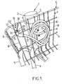
- Figure 1 a bicycle 1 having a frame 2 consisting of a frame 3 made from welded or brazed tubes.
- the chassis 2 comprises in particular a fork 4 rotating a front wheel 5 of the bicycle 1, this fork 4 being pivotally mounted on the frame 3, as shown in all the figures.
- the chassis 2 further comprises a luggage rack 6 fixed permanently on the fork 4.
- This rack is in the form of a basket made of a lattice 7 of vertical steel wires 8 and horizontal 9; it is fixed to the fork 4 by means of a metal insert plate which, overlapping several threads 8, 9 of the mesh 7, is screwed into the fork 4.
- the bicycle 1 is equipped with a built-in antitheft device 11, which comprises a cable 12 having a first end 13 permanently fixed to the frame 2, and a second mobile end 14, shaped as a hook.
- a built-in antitheft device 11 which comprises a cable 12 having a first end 13 permanently fixed to the frame 2, and a second mobile end 14, shaped as a hook.
- the fixed end 13 of the cable 12 is fixed permanently to the luggage rack 6, for example by being welded or screwed to the plate 10 for fixing it to the fork 4, as shown in FIG. 1.
- the movable end 14 of the cable 12 comprises to form a hook a cylindrical shaft 15 extended by a rod 16 of a diameter smaller than the shaft 15, this rod 16 being in turn extended by a pellet 17 of a diameter greater than that of the rod 16.
- the luggage rack 6 is provided with an additional bent wire 18, defining, with one of the vertical wires 8 of the mesh 7, a housing 19 substantially complementary to the hook 14, and into which the latter is inserted when the cable 12 is unused, as shown in Figure 1.
- This housing 19 has an upper portion 20, at which the spacing between the additional wire 18 and the wire 8 of the mesh 7 is sufficient to allow the introduction and removal of the hook 14, and a lower portion 21 to whereof the spacing between the additional wire 18 and the wire 8 of the mesh 7 is smaller than the diameter of the shaft 15 and that of the pellet 17, so that the hook 14, resting on a horizontal wire 9, is held there, except to raise it to place it at the right of the upper part 20, which allows its withdrawal.
- this latch 22 is in the form of a pivoting lever mounted articulated on a support 23 fixed to the frame 3 in the vicinity of the fork 4.
- a plate 24 is mounted on the fork 4, this plate 24 being in the form of a metal plate disposed in the plane of the fork 4, that is to say in a plane containing the axis of the front wheel 5 and the tubes which, forming the fork 4, are arranged on either side of the wheel 5 ( Figure 2).
- the latch 22 In its unlocking position, the latch 22 occupies a high position in which it is pressed against the frame 3, and allows the free rotation of the fork 4 relative thereto.
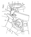
- the plate 24 comprises a groove 26 opening onto an upper edge 27 of the plate 24, this groove 26 being of a width slightly greater than the diameter of the rod 16 of the hook 14, the plate 24 also having a thickness slightly less than the length of this rod 16.
- the latch 22 is lowered to its locking position. In this position, the latch 22 is then adjacent to the groove 26, its leading edge 25 being substantially perpendicular thereto.
- the hook 14 is then locked relative to the plate 24, except to raise the latch 22 in its unlocking position to allow the withdrawal of the hook 14.
- Such an antitheft device 11 is particularly suitable for rental bicycles, their users thinking indeed rarely that to take with them an antitheft device.
- the antitheft device that has just been described can equip any type of cycles, such as motorcycles, scooters, mopeds.
Landscapes
- Engineering & Computer Science (AREA)
- Mechanical Engineering (AREA)
- Lock And Its Accessories (AREA)
- Steering Devices For Bicycles And Motorcycles (AREA)
- Motorcycle And Bicycle Frame (AREA)
- Burglar Alarm Systems (AREA)
Abstract
Description
- L'invention a trait aux cycles, et plus particulièrement aux dispositifs antivol pour cycles.
- On connaît de nombreux dispositifs antivol destinés aux cycles (et notamment aux bicyclettes). A titre d'exemple, citons l'antivol à câble, au moyen duquel on forme une boucle fermée qui attache, soit le cycle dans son ensemble à un élément de mobilier urbain (tel qu'un poteau ou un arbre), soit l'une des roues du cycle à son châssis afin d'en empêcher la libre rotation. Citons également les verrous en U, qui comportent une partie mâle sous la forme d'une tige rigide courbée que l'on enfile sur les rayons de l'une des roues du cycle, et une partie femelle que l'on vient encliqueter à l'extrémité de la partie mâle pour empêcher son retrait de la roue.
- L'efficacité de ces dispositifs antivol n'est pas contestée. Mais ils présentent pour principal inconvénient d'être encombrants et peuvent s'avérer d'un usage fastidieux. En particulier, compte tenu des diverses positions que peut adopter un cycle, et de la configuration du mobilier urbain sur laquelle celui-ci doit être attaché, il est parfois malaisé de raccorder les deux extrémités d'un antivol à câble, ou d'encliqueter la partie femelle d'un verrou en U à la partie mâle.
- L'invention vise notamment à remédier à ces inconvénients, en proposant un dispositif antivol présentant une commodité d'utilisation accrue.
- A cet effet, l'invention propose un dispositif antivol pour un cycle muni d'un châssis, ce dispositif comprenant un câble ayant une première extrémité fixée à demeure sur le châssis du cycle, et une seconde extrémité mobile, apte à coopérer avec un verrou monté sur le châssis, ce verrou étant mobile entre une position de verrouillage dans laquelle il bloque la seconde extrémité du câble par rapport au châssis, et une position de déverrouillage dans laquelle il libère cette seconde extrémité.
- De la sorte, il n'est pas nécessaire pour l'utilisateur de se munir d'un dispositif antivol séparé, celui-ci étant intégré au cycle. Il en résulte une commodité d'utilisation accrue. En particulier, il n'est pas nécessaire de faire coopérer les extrémités du câble, ce qui réduit le temps de mise en place de l'antivol.
- D'autres objets et avantages de l'invention apparaîtront à la lumière de la description faite ci-après en référence aux dessins annexés dans lesquels :
- la figure 1 est une vue en perspective partielle d'une bicyclette équipée d'un dispositif antivol selon l'invention ;
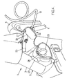
- les figures 2 à 5 sont des vues en perspective partielle montrant la bicyclette de la figure 1, suivant un autre angle de vue, et illustrant le mode opératoire de mise en place de l'antivol.
- Sur la figure 1 est représentée une bicyclette 1 comportant un châssis 2 composé d'un cadre 3 fabriqué à partir de tubes soudés ou brasés. Le châssis 2 comporte en particulier une fourche 4 portant à rotation une roue avant 5 de la bicyclette 1, cette fourche 4 étant montée pivotante sur le cadre 3, comme cela est représenté sur l'ensemble des figures.
- Comme cela est visible sur la figure 1, le châssis 2 comprend en outre un porte-bagages 6 fixé à demeure sur la fourche 4. Ce porte-bagages se présente sous la forme d'un panier fabriqué dans un treillis 7 de fils d'acier verticaux 8 et horizontaux 9 ; il est fixé à la fourche 4 au moyen d'une plaque 10 métallique rapportée qui, chevauchant plusieurs fils 8, 9 du treillis 7, est vissée dans la fourche 4.
- La bicyclette 1 est équipée d'un dispositif antivol 11 intégré, qui comporte un câble 12 ayant une première extrémité 13 fixée à demeure sur le châssis 2, et une seconde extrémité 14 mobile, conformée en crochet.
- Plus précisément, l'extrémité fixe 13 du câble 12 est fixée à demeure au porte-bagages 6, par exemple en étant soudée ou vissée à la plaque 10 de fixation de celui-ci à la fourche 4, comme cela est représenté sur la figure 1.
- Quant à l'extrémité mobile 14 du câble 12, elle comporte pour former crochet un arbre 15 cylindrique prolongé par une tige 16 d'un diamètre inférieur à l'arbre 15, cette tige 16 étant à son tour prolongée par une pastille 17 d'un diamètre supérieur à celui de la tige 16.
- Le porte-bagages 6 est muni d'un fil 18 supplémentaire coudé, définissant, avec l'un des fils verticaux 8 du treillis 7, un logement 19 sensiblement complémentaire du crochet 14, et dans lequel celui-ci est introduit lorsque le câble 12 est inutilisé, comme cela est représenté sur la figure 1.
- Ce logement 19 présente une partie supérieure 20, au niveau de laquelle l'écartement entre le fil supplémentaire 18 et le fil 8 du treillis 7 est suffisant pour permettre l'introduction et le retrait du crochet 14, ainsi qu'une partie inférieure 21 au niveau de laquelle l'écartement entre le fil supplémentaire 18 et le fil 8 du treillis 7 est inférieur au diamètre de l'arbre 15 et à celui de la pastille 17, de sorte que le crochet 14, reposant sur un fil horizontal 9, s'y trouve maintenu, sauf à le soulever pour le placer au droit de la partie supérieure 20, ce qui autorise son retrait.
- Le dispositif antivol 11 comporte en outre un verrou 22, monté sur le châssis 2 et avec lequel l'extrémité mobile 14 du câble 12 est apte à coopérer, ce verrou 22 étant mobile entre :
- une position de verrouillage dans laquelle il bloque la seconde extrémité 14 du câble 12 par rapport au châssis 2, et
- une position de déverrouillage dans laquelle il libère cette seconde extrémité 14 par rapport au châssis 2.
- Plus précisément, ce verrou 22 se présente sous la forme d'un levier pivotant, monté articulé sur un support 23 fixé sur le cadre 3 au voisinage de la fourche 4.
- Une platine 24 est montée sur la fourche 4, cette platine 24 se présentant sous la forme d'une plaque métallique disposée dans le plan de la fourche 4, c'est-à-dire dans un plan contenant l'axe de la roue avant 5 et les tubes qui, formant la fourche 4, sont disposés de part et d'autre de la roue 5 (figure 2).
- Dans sa position de déverrouillage, le verrou 22 occupe une position haute dans laquelle il est plaqué contre le cadre 3, et permet la libre rotation de la fourche 4 par rapport à celui-ci.
- Dans sa position de déverrouillage, il occupe au contraire une position basse dans laquelle l'un de ses bords, dit bord avant 25, se trouve en regard de la platine 24, après que la roue 5 a été tournée par rapport au cadre 3 d'un angle non nul.
- Comme cela est visible sur les figures 2 et 3 notamment, la platine 24 comprend une rainure 26 débouchant sur un bord supérieur 27 de la platine 24, cette rainure 26 étant d'une largeur légèrement supérieure au diamètre de la tige 16 du crochet 14, la platine 24 présentant par ailleurs une épaisseur légèrement inférieure à la longueur de cette tige 16.
- De la sorte, il est possible d'insérer le crochet 14 dans la rainure 26, comme cela est montré sur la figure 3, le crochet 14, maintenu de part et d'autre de la platine 24 par l'arbre 15 d'une part et la pastille 17 d'autre part, ne pouvant être retiré de la rainure 26 que par coulissement le long de la celle-ci.
- En partant d'une configuration dans laquelle le verrou 22 se trouve dans sa position de déverrouillage, et dans laquelle la roue avant 5 est tournée d'un angle non nul par rapport au cadre 3, angle suffisant pour permettre le libre pivotement du verrou 22 sans que celui-ci vienne buter contre la platine 24 (figure 2), la mise en place de l'antivol est réalisée comme suit. Dans cette configuration, le verrou 22 se trouve à distance de la platine 24 (et donc de la rainure).
- Après avoir fait usage du câble 12 de la manière classique (par exemple en entourant un élément de mobilier urbain tel qu'un poteau), on commence par introduire le crochet 14 dans la rainure 26 (figure 3).
- Puis on abaisse le verrou 22 vers sa position de verrouillage. Dans cette position, le verrou 22 est alors adjacent à la rainure 26, son bord avant 25 étant sensiblement perpendiculaire à celle-ci. Le crochet 14 se trouve alors bloqué par rapport à la platine 24, sauf à relever le verrou 22 dans sa position de déverrouillage pour permettre le retrait du crochet 14.
- Comme cela est représenté sur les figures 2 à 5, le support 23 est équipé d'une serrure 28 à clé 29, apte à adopter, par manoeuvre de la clé 29 :
- une position fermée (représentée sur la figure 4) dans laquelle le verrou 22 est maintenu dans sa position de verrouillage, et
- une position ouverte (figure 3) permettant le passage du verrou 22 de sa position de verrouillage à sa position de déverrouillage, et réciproquement.
- Ainsi, le retrait de la clé 29 de la serrure 28 (comme illustré sur la figure 5) bloque le verrou 22 dans sa position de verrouillage, et assure ainsi le maintien du crochet 14 sur la platine 24. La bicyclette 1 se trouve ainsi accrochée au mobilier urbain choisi par l'utilisateur, seul autorisé à l'en décrocher par manoeuvre de la clé 29 dans la serrure 28.
- Il est ainsi possible d'assurer la mise en place de l'antivol par simple manoeuvre de l'extrémité libre 14 du câble 12. Celui-ci étant fixé, par son extrémité opposée 13, au châssis 2 (en l'occurrence au porte-bagages 6), il n'est pas nécessaire de se munir d'un dispositif antivol séparé.
- Un tel dispositif antivol 11 est particulièrement adapté aux bicyclettes de location, leurs utilisateurs ne pensant en effet que rarement à emporter avec eux un dispositif antivol.
- Les dispositions qui assurent d'une part le verrouillage du câble 12 et d'autre part le blocage de la roue avant 5 dans une position tournée par rapport au cadre 3 sont complémentaires : l'éventuelle section du câble 12 au moyen d'un objet tranchant ne libère pas totalement la bicyclette 1, sa roue avant 5 se trouvant dans une position empêchant le roulage en ligne droite.
- Il va de soi que, bien que particulièrement adapté aux bicyclettes, le dispositif antivol qui vient d'être décrit peut équiper tout type de cycles, tels que motos, scooters, mobylettes.
Claims (7)
- Dispositif antivol (11) pour un cycle (1) muni d'un châssis (2), caractérisé en ce qu'il comprend un câble (12) ayant une première extrémité (13) fixée à demeure sur le châssis (2), et une seconde extrémité (14) mobile, apte à coopérer avec un verrou (22) monté sur le châssis (2), ce verrou (22) étant mobile entre une position de verrouillage dans laquelle il bloque la seconde extrémité (14) du câble (12) par rapport au châssis (2), et une position de déverrouillage dans laquelle il libère cette seconde extrémité (14) par rapport au châssis (2).
- Dispositif antivol (11) selon la revendication 1, dans lequel la seconde extrémité (14) du câble (12) est conformée en crochet, et dans lequel le dispositif antivol (11) comprend une platine (24) montée sur le châssis (22), cette platine (24) comprenant une rainure (26) dans laquelle le crochet (14) est apte à être inséré.
- Dispositif antivol (11) selon la revendication 2, dans lequel, dans sa position de déverrouillage le verrou (22) se trouve à distance de la rainure (26), tandis que, dans sa position de verrouillage, il est adjacent à celle-ci.
- Dispositif antivol (11) selon la revendication 2 ou 3, dans lequel, le châssis (2) du cycle (1) comportant un cadre (3) sur lequel est montée pivotante une fourche (4) portant une roue avant (5), la platine (24) est montée sur cette fourche (4).
- Dispositif antivol (11) selon la revendication 4, dans lequel le verrou (22) ne peut occuper sa position de déverrouillage que lorsque la roue avant (5) forme avec le cadre (3) un angle non nul.
- Dispositif antivol (11) selon l'une des revendications 1 à 5, qui comporte une serrure (28) à clé (29) montée sur le châssis (2) du cycle (1), cette serrure (28) étant apte à adopter par manoeuvre de la clé (29) une position fermée dans laquelle le verrou (22) est maintenu dans sa position de verrouillage, et une position ouverte permettant le passage du verrou (22) de sa position de verrouillage à sa position de déverrouillage, et réciproquement.
- Cycle (1) équipé d'un dispositif antivol (11) selon l'une des revendications 1 à 6.
Applications Claiming Priority (1)
| Application Number | Priority Date | Filing Date | Title |
|---|---|---|---|
| FR0411927A FR2877634B1 (fr) | 2004-11-09 | 2004-11-09 | Dispositif antivol a cable pour un cycle et cycle equipe d'un tel dispositif |
Publications (2)
| Publication Number | Publication Date |
|---|---|
| EP1655214A1 true EP1655214A1 (fr) | 2006-05-10 |
| EP1655214B1 EP1655214B1 (fr) | 2009-04-15 |
Family
ID=34951489
Family Applications (1)
| Application Number | Title | Priority Date | Filing Date |
|---|---|---|---|
| EP20050292237 Revoked EP1655214B1 (fr) | 2004-11-09 | 2005-10-24 | Dispositif antivol à câble pour un cycle et cycle equipé d'un tel dispositif |
Country Status (9)
| Country | Link |
|---|---|
| US (1) | US7281399B2 (fr) |
| EP (1) | EP1655214B1 (fr) |
| AT (1) | ATE428623T1 (fr) |
| AU (1) | AU2005232268B2 (fr) |
| CA (1) | CA2524872A1 (fr) |
| DE (1) | DE602005013885D1 (fr) |
| ES (1) | ES2325815T3 (fr) |
| FR (1) | FR2877634B1 (fr) |
| PT (1) | PT1655214E (fr) |
Families Citing this family (11)
| Publication number | Priority date | Publication date | Assignee | Title |
|---|---|---|---|---|
| FR2897589B1 (fr) * | 2006-02-21 | 2008-05-16 | J C Decaux Sa | Systeme automatique de stockage de cycles |
| US8132437B1 (en) * | 2011-01-20 | 2012-03-13 | Sinox Lock (Kushan) Co. Ltd. | Bicycle lock |
| USD730779S1 (en) | 2014-08-15 | 2015-06-02 | Technologies Bewegen Inc. | Electric bicycle |
| USD730780S1 (en) | 2014-08-15 | 2015-06-02 | Technologies Bewegen Inc. | Bicycle |
| USD746760S1 (en) | 2014-08-15 | 2016-01-05 | Technologies Bewegen Inc. | Bicycle basket |
| USD766138S1 (en) | 2014-08-15 | 2016-09-13 | Technologies Bewegen Inc. | Base station for a bicycle sharing system |
| USD730781S1 (en) | 2014-08-18 | 2015-06-02 | Technologies Bewegen Inc. | Electric bicycle |
| USD738276S1 (en) | 2014-08-18 | 2015-09-08 | Technologies Bewegen Inc. | Bicycle handlebar |
| USD776576S1 (en) | 2014-08-18 | 2017-01-17 | Technologies Bewegen Inc. | Electric bicycle |
| USD894050S1 (en) * | 2019-02-10 | 2020-08-25 | Lyft, Inc. | Fender with integrated lock |
| DE112020004930A5 (de) * | 2019-10-13 | 2022-06-23 | WATERMAN Charging System GmbH | Verbindungsvorrichtung zum Verbinden eines Kleinfahrzeugs mit einer Basisstation |
Citations (6)
| Publication number | Priority date | Publication date | Assignee | Title |
|---|---|---|---|---|
| US3950972A (en) * | 1975-05-05 | 1976-04-20 | Bik-Lok, Inc. | Bicycle lock |
| US4028916A (en) * | 1976-04-13 | 1977-06-14 | Pender David R | Lock for bicycles and the like |
| US4086795A (en) * | 1976-02-26 | 1978-05-02 | The Firestone Tire & Rubber Company | Cable lock storage structure |
| US4776188A (en) * | 1986-12-23 | 1988-10-11 | O. Gene Dalaba | Locking and alarm combination security device |
| DE29624281U1 (de) * | 1995-09-01 | 2001-08-30 | Trelock GmbH, 48301 Nottuln | Mitführbefestigung eine Zubehörteils an einem mobilen Objekt |
| FR2837781A1 (fr) * | 2002-03-29 | 2003-10-03 | Ard | Appareil pour la location ou le stationnement securise d'articles par exemple des cycles |
Family Cites Families (12)
| Publication number | Priority date | Publication date | Assignee | Title |
|---|---|---|---|---|
| US583893A (en) * | 1897-06-08 | davidson | ||
| US2140489A (en) * | 1936-10-29 | 1938-12-13 | Wise Solomon | Lock device |
| US2180117A (en) * | 1937-09-30 | 1939-11-14 | Sears Roebuck & Co | Locking device |
| US4055060A (en) * | 1973-07-09 | 1977-10-25 | Jim Bellino | Bicycle lock |
| US4012930A (en) * | 1975-10-24 | 1977-03-22 | Benson Everett H | Locks |
| US4033160A (en) * | 1976-03-08 | 1977-07-05 | Mima James J | Bicycle lock |
| US4099394A (en) * | 1977-05-31 | 1978-07-11 | Laszlo Joo | Bicycle cable locking device |
| US4404822A (en) * | 1981-05-18 | 1983-09-20 | Green Leonard O | Pre-coiled cable-lock device |
| US4490997A (en) * | 1983-04-25 | 1985-01-01 | Hughes Leland G | Bicycle locking device |
| US4811577A (en) * | 1986-07-02 | 1989-03-14 | Webster Noel E | Portable locking device |
| US4945739A (en) * | 1989-06-01 | 1990-08-07 | Prindle Carl E | Bicycle lock |
| GB9311099D0 (en) * | 1993-05-28 | 1993-07-14 | White Peter A | Improvements in locks for bicycles and the like |
-
2004
- 2004-11-09 FR FR0411927A patent/FR2877634B1/fr not_active Expired - Fee Related
-
2005
- 2005-10-24 EP EP20050292237 patent/EP1655214B1/fr not_active Revoked
- 2005-10-24 ES ES05292237T patent/ES2325815T3/es not_active Expired - Lifetime
- 2005-10-24 PT PT05292237T patent/PT1655214E/pt unknown
- 2005-10-24 AT AT05292237T patent/ATE428623T1/de not_active IP Right Cessation
- 2005-10-24 DE DE200560013885 patent/DE602005013885D1/de not_active Expired - Lifetime
- 2005-11-01 CA CA 2524872 patent/CA2524872A1/fr not_active Abandoned
- 2005-11-04 US US11/267,438 patent/US7281399B2/en not_active Expired - Fee Related
- 2005-11-09 AU AU2005232268A patent/AU2005232268B2/en not_active Ceased
Patent Citations (6)
| Publication number | Priority date | Publication date | Assignee | Title |
|---|---|---|---|---|
| US3950972A (en) * | 1975-05-05 | 1976-04-20 | Bik-Lok, Inc. | Bicycle lock |
| US4086795A (en) * | 1976-02-26 | 1978-05-02 | The Firestone Tire & Rubber Company | Cable lock storage structure |
| US4028916A (en) * | 1976-04-13 | 1977-06-14 | Pender David R | Lock for bicycles and the like |
| US4776188A (en) * | 1986-12-23 | 1988-10-11 | O. Gene Dalaba | Locking and alarm combination security device |
| DE29624281U1 (de) * | 1995-09-01 | 2001-08-30 | Trelock GmbH, 48301 Nottuln | Mitführbefestigung eine Zubehörteils an einem mobilen Objekt |
| FR2837781A1 (fr) * | 2002-03-29 | 2003-10-03 | Ard | Appareil pour la location ou le stationnement securise d'articles par exemple des cycles |
Also Published As
| Publication number | Publication date |
|---|---|
| FR2877634B1 (fr) | 2008-08-08 |
| FR2877634A1 (fr) | 2006-05-12 |
| AU2005232268B2 (en) | 2011-03-10 |
| ATE428623T1 (de) | 2009-05-15 |
| PT1655214E (pt) | 2009-07-16 |
| ES2325815T3 (es) | 2009-09-18 |
| EP1655214B1 (fr) | 2009-04-15 |
| US20060096341A1 (en) | 2006-05-11 |
| US7281399B2 (en) | 2007-10-16 |
| DE602005013885D1 (de) | 2009-05-28 |
| AU2005232268A1 (en) | 2006-05-25 |
| CA2524872A1 (fr) | 2006-05-09 |
Similar Documents
| Publication | Publication Date | Title |
|---|---|---|
| EP1655214B1 (fr) | Dispositif antivol à câble pour un cycle et cycle equipé d'un tel dispositif | |
| EP0669225B1 (fr) | Porte-cycle et son dispositif de fixation d'un cycle | |
| EP2003268B1 (fr) | Attache de support et de fixation d'une structure sur une paroi, structure associée, et ensemble de structure correspondant | |
| FR2791384A1 (fr) | Ferrure de commande pour un ouvrant coulissant | |
| EP1126108B1 (fr) | Organe de rétention pour serrure de véhicule automobile, son procédé de fabrication, et serrure comportant un tel organe de rétention | |
| EP1655213A2 (fr) | Dispositif antivol de maintien en stationnement d'un véhicule à deux roues | |
| EP1835078B1 (fr) | Equipement de voirie | |
| EP0880449A1 (fr) | Dispositif de maintien d'une bicyclette en stationnement comportant un anti-vol | |
| FR2978417A1 (fr) | Vehicule repliable, par exemple du type trottinette | |
| EP1723005B1 (fr) | Porte-charge destine a equiper l arriere d un vehicule automobile | |
| FR2960847A1 (fr) | Dispositif antivol de cycles | |
| EP0854802A1 (fr) | Antivol bloque-pedales de frein et d'embrayage voitures | |
| EP1093430B1 (fr) | Dispositif d'immobilisation d'un vehicule notamment a deux roues | |
| EP1409333A1 (fr) | Dispositif de stationnement d'un cycle | |
| FR2928617A1 (fr) | Bequille telescopique pour le stationnement de vehicule a deux roues. | |
| FR2598669A1 (fr) | Dispositif antivol pour un engin a deux roues | |
| FR2723716A1 (fr) | Dispositif de maintien et d'assujettissement contre le vol, en particulier pour deux-roues | |
| FR2672632A1 (fr) | Dispositif antivol de semi-remorque. | |
| FR2924401A1 (fr) | Dispositif antivol pour tout vehicule dont la transmission est assuree par chaine ou courroie, particulierement adapte aux velos et motos | |
| WO1987001669A1 (fr) | Dispositif anti-vol pour vehicules a deux-roues | |
| FR3058980A1 (fr) | Support antivol pour cycles | |
| BE516904A (fr) | ||
| FR2763554A1 (fr) | Dispositif antivol de stationnement pour cycles ou cyclomoteurs | |
| FR3146052A1 (fr) | Dispositif de sécurité pour broche de présentoir de magasin | |
| FR3136739A1 (fr) | Dispositif d’attache pour vehicule |
Legal Events
| Date | Code | Title | Description |
|---|---|---|---|
| PUAI | Public reference made under article 153(3) epc to a published international application that has entered the european phase |
Free format text: ORIGINAL CODE: 0009012 |
|
| AK | Designated contracting states |
Kind code of ref document: A1 Designated state(s): AT BE BG CH CY CZ DE DK EE ES FI FR GB GR HU IE IS IT LI LT LU LV MC NL PL PT RO SE SI SK TR |
|
| AX | Request for extension of the european patent |
Extension state: AL BA HR MK YU |
|
| 17P | Request for examination filed |
Effective date: 20060518 |
|
| AKX | Designation fees paid |
Designated state(s): AT BE BG CH CY CZ DE DK EE ES FI FR GB GR HU IE IS IT LI LT LU LV MC NL PL PT RO SE SI SK TR |
|
| 17Q | First examination report despatched |
Effective date: 20080710 |
|
| GRAP | Despatch of communication of intention to grant a patent |
Free format text: ORIGINAL CODE: EPIDOSNIGR1 |
|
| GRAS | Grant fee paid |
Free format text: ORIGINAL CODE: EPIDOSNIGR3 |
|
| GRAA | (expected) grant |
Free format text: ORIGINAL CODE: 0009210 |
|
| AK | Designated contracting states |
Kind code of ref document: B1 Designated state(s): AT BE BG CH CY CZ DE DK EE ES FI FR GB GR HU IE IS IT LI LT LU LV MC NL PL PT RO SE SI SK TR |
|
| REG | Reference to a national code |
Ref country code: CH Ref legal event code: EP Ref country code: GB Ref legal event code: FG4D Free format text: NOT ENGLISH |
|
| REG | Reference to a national code |
Ref country code: IE Ref legal event code: FG4D |
|
| REF | Corresponds to: |
Ref document number: 602005013885 Country of ref document: DE Date of ref document: 20090528 Kind code of ref document: P |
|
| REG | Reference to a national code |
Ref country code: CH Ref legal event code: NV Representative=s name: KELLER & PARTNER PATENTANWAELTE AG |
|
| REG | Reference to a national code |
Ref country code: PT Ref legal event code: SC4A Free format text: AVAILABILITY OF NATIONAL TRANSLATION Effective date: 20090710 |
|
| REG | Reference to a national code |
Ref country code: ES Ref legal event code: FG2A Ref document number: 2325815 Country of ref document: ES Kind code of ref document: T3 |
|
| NLV1 | Nl: lapsed or annulled due to failure to fulfill the requirements of art. 29p and 29m of the patents act | ||
| PG25 | Lapsed in a contracting state [announced via postgrant information from national office to epo] |
Ref country code: AT Free format text: LAPSE BECAUSE OF FAILURE TO SUBMIT A TRANSLATION OF THE DESCRIPTION OR TO PAY THE FEE WITHIN THE PRESCRIBED TIME-LIMIT Effective date: 20090415 Ref country code: FI Free format text: LAPSE BECAUSE OF FAILURE TO SUBMIT A TRANSLATION OF THE DESCRIPTION OR TO PAY THE FEE WITHIN THE PRESCRIBED TIME-LIMIT Effective date: 20090415 Ref country code: LT Free format text: LAPSE BECAUSE OF FAILURE TO SUBMIT A TRANSLATION OF THE DESCRIPTION OR TO PAY THE FEE WITHIN THE PRESCRIBED TIME-LIMIT Effective date: 20090415 |
|
| PG25 | Lapsed in a contracting state [announced via postgrant information from national office to epo] |
Ref country code: NL Free format text: LAPSE BECAUSE OF FAILURE TO SUBMIT A TRANSLATION OF THE DESCRIPTION OR TO PAY THE FEE WITHIN THE PRESCRIBED TIME-LIMIT Effective date: 20090415 Ref country code: PL Free format text: LAPSE BECAUSE OF FAILURE TO SUBMIT A TRANSLATION OF THE DESCRIPTION OR TO PAY THE FEE WITHIN THE PRESCRIBED TIME-LIMIT Effective date: 20090415 Ref country code: SI Free format text: LAPSE BECAUSE OF FAILURE TO SUBMIT A TRANSLATION OF THE DESCRIPTION OR TO PAY THE FEE WITHIN THE PRESCRIBED TIME-LIMIT Effective date: 20090415 Ref country code: SE Free format text: LAPSE BECAUSE OF FAILURE TO SUBMIT A TRANSLATION OF THE DESCRIPTION OR TO PAY THE FEE WITHIN THE PRESCRIBED TIME-LIMIT Effective date: 20090715 Ref country code: LV Free format text: LAPSE BECAUSE OF FAILURE TO SUBMIT A TRANSLATION OF THE DESCRIPTION OR TO PAY THE FEE WITHIN THE PRESCRIBED TIME-LIMIT Effective date: 20090415 Ref country code: IS Free format text: LAPSE BECAUSE OF FAILURE TO SUBMIT A TRANSLATION OF THE DESCRIPTION OR TO PAY THE FEE WITHIN THE PRESCRIBED TIME-LIMIT Effective date: 20090815 |
|
| REG | Reference to a national code |
Ref country code: IE Ref legal event code: FD4D |
|
| PLBI | Opposition filed |
Free format text: ORIGINAL CODE: 0009260 |
|
| PG25 | Lapsed in a contracting state [announced via postgrant information from national office to epo] |
Ref country code: RO Free format text: LAPSE BECAUSE OF FAILURE TO SUBMIT A TRANSLATION OF THE DESCRIPTION OR TO PAY THE FEE WITHIN THE PRESCRIBED TIME-LIMIT Effective date: 20090415 Ref country code: CZ Free format text: LAPSE BECAUSE OF FAILURE TO SUBMIT A TRANSLATION OF THE DESCRIPTION OR TO PAY THE FEE WITHIN THE PRESCRIBED TIME-LIMIT Effective date: 20090415 Ref country code: IE Free format text: LAPSE BECAUSE OF FAILURE TO SUBMIT A TRANSLATION OF THE DESCRIPTION OR TO PAY THE FEE WITHIN THE PRESCRIBED TIME-LIMIT Effective date: 20090415 Ref country code: EE Free format text: LAPSE BECAUSE OF FAILURE TO SUBMIT A TRANSLATION OF THE DESCRIPTION OR TO PAY THE FEE WITHIN THE PRESCRIBED TIME-LIMIT Effective date: 20090415 Ref country code: DK Free format text: LAPSE BECAUSE OF FAILURE TO SUBMIT A TRANSLATION OF THE DESCRIPTION OR TO PAY THE FEE WITHIN THE PRESCRIBED TIME-LIMIT Effective date: 20090415 |
|
| PLAX | Notice of opposition and request to file observation + time limit sent |
Free format text: ORIGINAL CODE: EPIDOSNOBS2 |
|
| 26 | Opposition filed |
Opponent name: CLEAR CHANNEL FRANCE Effective date: 20100114 |
|
| PG25 | Lapsed in a contracting state [announced via postgrant information from national office to epo] |
Ref country code: SK Free format text: LAPSE BECAUSE OF FAILURE TO SUBMIT A TRANSLATION OF THE DESCRIPTION OR TO PAY THE FEE WITHIN THE PRESCRIBED TIME-LIMIT Effective date: 20090415 |
|
| PG25 | Lapsed in a contracting state [announced via postgrant information from national office to epo] |
Ref country code: BG Free format text: LAPSE BECAUSE OF FAILURE TO SUBMIT A TRANSLATION OF THE DESCRIPTION OR TO PAY THE FEE WITHIN THE PRESCRIBED TIME-LIMIT Effective date: 20090715 |
|
| PG25 | Lapsed in a contracting state [announced via postgrant information from national office to epo] |
Ref country code: MC Free format text: LAPSE BECAUSE OF NON-PAYMENT OF DUE FEES Effective date: 20091031 |
|
| PLBB | Reply of patent proprietor to notice(s) of opposition received |
Free format text: ORIGINAL CODE: EPIDOSNOBS3 |
|
| PG25 | Lapsed in a contracting state [announced via postgrant information from national office to epo] |
Ref country code: GR Free format text: LAPSE BECAUSE OF FAILURE TO SUBMIT A TRANSLATION OF THE DESCRIPTION OR TO PAY THE FEE WITHIN THE PRESCRIBED TIME-LIMIT Effective date: 20090716 |
|
| PG25 | Lapsed in a contracting state [announced via postgrant information from national office to epo] |
Ref country code: LU Free format text: LAPSE BECAUSE OF NON-PAYMENT OF DUE FEES Effective date: 20091024 |
|
| PG25 | Lapsed in a contracting state [announced via postgrant information from national office to epo] |
Ref country code: HU Free format text: LAPSE BECAUSE OF FAILURE TO SUBMIT A TRANSLATION OF THE DESCRIPTION OR TO PAY THE FEE WITHIN THE PRESCRIBED TIME-LIMIT Effective date: 20091016 |
|
| PG25 | Lapsed in a contracting state [announced via postgrant information from national office to epo] |
Ref country code: TR Free format text: LAPSE BECAUSE OF FAILURE TO SUBMIT A TRANSLATION OF THE DESCRIPTION OR TO PAY THE FEE WITHIN THE PRESCRIBED TIME-LIMIT Effective date: 20090415 |
|
| PG25 | Lapsed in a contracting state [announced via postgrant information from national office to epo] |
Ref country code: CY Free format text: LAPSE BECAUSE OF FAILURE TO SUBMIT A TRANSLATION OF THE DESCRIPTION OR TO PAY THE FEE WITHIN THE PRESCRIBED TIME-LIMIT Effective date: 20090415 |
|
| PLAB | Opposition data, opponent's data or that of the opponent's representative modified |
Free format text: ORIGINAL CODE: 0009299OPPO |
|
| REG | Reference to a national code |
Ref country code: DE Ref legal event code: R103 Ref document number: 602005013885 Country of ref document: DE Ref country code: DE Ref legal event code: R064 Ref document number: 602005013885 Country of ref document: DE |
|
| PLAB | Opposition data, opponent's data or that of the opponent's representative modified |
Free format text: ORIGINAL CODE: 0009299OPPO |
|
| PLAO | Information deleted related to despatch of communication that opposition is rejected |
Free format text: ORIGINAL CODE: EPIDOSDREJ1 |
|
| PLCK | Communication despatched that opposition was rejected |
Free format text: ORIGINAL CODE: EPIDOSNREJ1 |
|
| RDAF | Communication despatched that patent is revoked |
Free format text: ORIGINAL CODE: EPIDOSNREV1 |
|
| R26 | Opposition filed (corrected) |
Opponent name: CLEAR CHANNEL FRANCE Effective date: 20100114 |
|
| R26 | Opposition filed (corrected) |
Opponent name: CLEAR CHANNEL FRANCE Effective date: 20100114 |
|
| PGFP | Annual fee paid to national office [announced via postgrant information from national office to epo] |
Ref country code: BE Payment date: 20121025 Year of fee payment: 8 Ref country code: PT Payment date: 20120424 Year of fee payment: 8 Ref country code: FR Payment date: 20121128 Year of fee payment: 8 Ref country code: CH Payment date: 20121019 Year of fee payment: 8 Ref country code: DE Payment date: 20121011 Year of fee payment: 8 |
|
| PGFP | Annual fee paid to national office [announced via postgrant information from national office to epo] |
Ref country code: GB Payment date: 20121023 Year of fee payment: 8 Ref country code: IT Payment date: 20121022 Year of fee payment: 8 Ref country code: ES Payment date: 20121022 Year of fee payment: 8 |
|
| PLAB | Opposition data, opponent's data or that of the opponent's representative modified |
Free format text: ORIGINAL CODE: 0009299OPPO |
|
| RDAG | Patent revoked |
Free format text: ORIGINAL CODE: 0009271 |
|
| STAA | Information on the status of an ep patent application or granted ep patent |
Free format text: STATUS: PATENT REVOKED |
|
| REG | Reference to a national code |
Ref country code: CH Ref legal event code: PL |
|
| R26 | Opposition filed (corrected) |
Opponent name: CLEAR CHANNEL FRANCE Effective date: 20100114 |
|
| REG | Reference to a national code |
Ref country code: PT Ref legal event code: MP4A Effective date: 20130424 |
|
| 27W | Patent revoked |
Effective date: 20121121 |
|
| GBPR | Gb: patent revoked under art. 102 of the ep convention designating the uk as contracting state |
Effective date: 20121121 |
|
| PG25 | Lapsed in a contracting state [announced via postgrant information from national office to epo] |
Ref country code: CH Free format text: LAPSE BECAUSE OF THE APPLICANT RENOUNCES Effective date: 20090415 Ref country code: LI Free format text: LAPSE BECAUSE OF THE APPLICANT RENOUNCES Effective date: 20090415 |
|
| REG | Reference to a national code |
Ref country code: DE Ref legal event code: R107 Ref document number: 602005013885 Country of ref document: DE Effective date: 20130926 |