EP1654952B1 - Umbrella opening and closing device - Google Patents
Umbrella opening and closing device Download PDFInfo
- Publication number
- EP1654952B1 EP1654952B1 EP05255342.7A EP05255342A EP1654952B1 EP 1654952 B1 EP1654952 B1 EP 1654952B1 EP 05255342 A EP05255342 A EP 05255342A EP 1654952 B1 EP1654952 B1 EP 1654952B1
- Authority
- EP
- European Patent Office
- Prior art keywords
- umbrella
- assembly
- actuating handle
- support pole
- hub
- Prior art date
- Legal status (The legal status is an assumption and is not a legal conclusion. Google has not performed a legal analysis and makes no representation as to the accuracy of the status listed.)
- Active
Links
- 230000007935 neutral effect Effects 0.000 claims description 3
- 230000007246 mechanism Effects 0.000 description 23
- 239000000463 material Substances 0.000 description 11
- 238000010276 construction Methods 0.000 description 7
- 238000005260 corrosion Methods 0.000 description 4
- 230000007797 corrosion Effects 0.000 description 4
- 230000005484 gravity Effects 0.000 description 4
- 238000004519 manufacturing process Methods 0.000 description 4
- 230000003466 anti-cipated effect Effects 0.000 description 3
- 238000011109 contamination Methods 0.000 description 3
- 239000004744 fabric Substances 0.000 description 3
- 230000000712 assembly Effects 0.000 description 2
- 238000000429 assembly Methods 0.000 description 2
- 230000002146 bilateral effect Effects 0.000 description 2
- 230000006835 compression Effects 0.000 description 2
- 238000007906 compression Methods 0.000 description 2
- 238000005297 material degradation process Methods 0.000 description 2
- 238000003860 storage Methods 0.000 description 2
- 230000000007 visual effect Effects 0.000 description 2
- 239000002023 wood Substances 0.000 description 2
- 229910000838 Al alloy Inorganic materials 0.000 description 1
- 229920000049 Carbon (fiber) Polymers 0.000 description 1
- 229910000831 Steel Inorganic materials 0.000 description 1
- 229910001069 Ti alloy Inorganic materials 0.000 description 1
- 238000005452 bending Methods 0.000 description 1
- 230000037396 body weight Effects 0.000 description 1
- 239000004917 carbon fiber Substances 0.000 description 1
- 239000011248 coating agent Substances 0.000 description 1
- 238000000576 coating method Methods 0.000 description 1
- 238000004040 coloring Methods 0.000 description 1
- 230000008878 coupling Effects 0.000 description 1
- 238000010168 coupling process Methods 0.000 description 1
- 238000005859 coupling reaction Methods 0.000 description 1
- 230000001419 dependent effect Effects 0.000 description 1
- 230000007613 environmental effect Effects 0.000 description 1
- 210000003608 fece Anatomy 0.000 description 1
- 239000012467 final product Substances 0.000 description 1
- 230000001771 impaired effect Effects 0.000 description 1
- 230000001939 inductive effect Effects 0.000 description 1
- 239000003562 lightweight material Substances 0.000 description 1
- VNWKTOKETHGBQD-UHFFFAOYSA-N methane Chemical compound C VNWKTOKETHGBQD-UHFFFAOYSA-N 0.000 description 1
- 238000000034 method Methods 0.000 description 1
- 230000003387 muscular Effects 0.000 description 1
- NJPPVKZQTLUDBO-UHFFFAOYSA-N novaluron Chemical compound C1=C(Cl)C(OC(F)(F)C(OC(F)(F)F)F)=CC=C1NC(=O)NC(=O)C1=C(F)C=CC=C1F NJPPVKZQTLUDBO-UHFFFAOYSA-N 0.000 description 1
- 238000004806 packaging method and process Methods 0.000 description 1
- 230000002093 peripheral effect Effects 0.000 description 1
- 239000004033 plastic Substances 0.000 description 1
- 229920003023 plastic Polymers 0.000 description 1
- 239000002985 plastic film Substances 0.000 description 1
- 229920006255 plastic film Polymers 0.000 description 1
- 230000036316 preload Effects 0.000 description 1
- 230000000452 restraining effect Effects 0.000 description 1
- 230000000717 retained effect Effects 0.000 description 1
- 238000005096 rolling process Methods 0.000 description 1
- 239000010959 steel Substances 0.000 description 1
- 238000006467 substitution reaction Methods 0.000 description 1
Images


Classifications
-
- A—HUMAN NECESSITIES
- A45—HAND OR TRAVELLING ARTICLES
- A45B—WALKING STICKS; UMBRELLAS; LADIES' OR LIKE FANS
- A45B25/00—Details of umbrellas
- A45B25/14—Devices for opening and for closing umbrellas
-
- A—HUMAN NECESSITIES
- A45—HAND OR TRAVELLING ARTICLES
- A45B—WALKING STICKS; UMBRELLAS; LADIES' OR LIKE FANS
- A45B19/00—Special folding or telescoping of umbrellas
- A45B19/04—Special folding or telescoping of umbrellas with telescopic sticks
-
- A—HUMAN NECESSITIES
- A45—HAND OR TRAVELLING ARTICLES
- A45B—WALKING STICKS; UMBRELLAS; LADIES' OR LIKE FANS
- A45B23/00—Other umbrellas
Landscapes
- Walking Sticks, Umbrellas, And Fans (AREA)
Description
- The invention relates to the feld of umbrellas and to an opening/closing mechanism for umbrellas that offers simplified opening/closing operation and securing of the umbrella, in a set opening position as well as improved aesthetics.
- Umbrellas are popular devices which can be utilized outdoors to provide shade from the sun and shelter from the elements. Umbrellas typically include the capability to be placed in an open or erect configuration to provide the shelter and shade function, as well as to be closed or collapsed to facilitate movement and storage of the umbrellas. Many umbrellas are relatively large having canopy diameters on the order of several meters when opened to provide the desired shade and shelter. Accordingly, some type of opening mechanism is frequently provided to facilitate opening and closing of the umbrella.
- A variety of opening/closing mechanisms are known for umbrellas which may include crank and pulley arrangements, levers, and/or rack and pinion arrangements. Such mechanisms tend to be relatively complex, which increases the manufacturing costs for the umbrellas and the corresponding sale or purchase price to the end user. In addition, the relatively complex mechanisms present numerous potential failure modes, as well as increased susceptibility to contamination and jamming by foreign debris material and corrosion and material degradation from environmental factors.
- Dutch Patent Publication No.
NL9500219 - A further drawback to known umbrella opening/closing mechanisms is that the relatively complex mechanisms tend to result in operational structures, which are not particularly aesthetically pleasing to observers. For example, crank mechanisms and lever-operated mechanisms generally include a user actuation member or crank which extends or is extendable outward to allow a user to manipulate the mechanism. However, such cranks or levers tend to be quite mechanical and utilitarian in appearance which can detract from a desirable aesthetic appearance of the overall umbrella. As umbrellas are frequently employed both for their aesthetic appearance, as well as for the utility of shade and shelter, it will be understood that a pleasing aesthetical appearance is a highly desirable feature in an umbrella.
- Known from the prior art are
NL9500219 US5329953 but in spite of the disclosure of these documents there remains a need for an umbrella that addresses the requirements of consumers and which at least provides a useful alternative to prior umbrellas. - From the foregoing, it will be appreciated that there is a desire for an umbrella opening/closing mechanism which is of simplified constriction to both reduce the construction/manufacturing costs of the umbrella, as well as to reduce susceptibility to material contamination and material degradation and corrosion. It is also desirable that an umbrella opening/closing mechanism facilitate opening and closing of a relatively large umbrella without excessive applied user force, for example, by incorporating mechanical advantage. There is also a desire for an umbrella having opening and closing mechanism which presents a pleasing symmetrical and mechanically uncluttered aesthetic appearance.
- According to the present invention there is provided an umbrella, comprising: a support pole assembly comprising: a lower pole having a lower end and an upper end; an upper pole vertically translatable relative to the lower pole; a canopy support frame comprising: an upper hub coupled with the upper pole and with a plurality of ribs; and an actuating handle coupled with the upper pole and translatable relative to the lower pole so that, when the actuating handle is raised, the upper pole and the upper hub are raised causing the canopy support frame to close; distal ends of first erection members pivotably connected along intermediate points to the ribs, proximal ends of the first erection members pivotably connected in a third, lower hub; distal ends of second erection members pivotably connected to intermediate points of the first erection members with proximal ends of the second erection members pivotably connected with a second, intermediate hub.
- Preferably the relative lengths of the ribs and first and second erection members, as well as a location of corresponding intermediate points of the ribs and first erection members to which the first erection members and second erection members are respectively interconnected are selected to provide mechanical advantage to reduce a force required to be applied to the actuating handle to raise or lower the umbrella. It is particularly preferred that the selection of lengths and location produce a weight neutral configuration of the umbrella, such that weight loads of the umbrella are substantially balanced such that, absent an opening or closing applied force, the umbrella is balanced and not induced to either close or open.
- Preferably in use the upper and third hubs are moved relative to the intermediate hub to close or open the umbrella.
- Preferably the actuating handle is coupled with the support pole assembly for translation along an axis parallel to a longitudinal axis of the support pole assembly.
- Preferably the actuating handle has a first position relative to the support pole assembly in which the actuating handle is spaced from a side surface of the support pole assembly to permit vertical movement of the actuating handle, said vertical movement raising or lowering at least one of the hubs, and a second position relative to the support pole assembly in which the actuating handle frictionally engages a side surface of the support pole assembly to inhibit vertical movement of the actuating handle. The actuating handle preferably comprises a hand-gripping portion and a frictional surface moveable into engagement with the side surface of the support pole assembly. Preferably the actuating handle is configured such that rotation of the hand-gripping portion causes the frictional surface to move transversely to the support pole assembly into engagement with the support pole assembly and out of engagement with the support pole assembly. Preferably the hand-gripping portion is symmetrical about an axis extending transverse to the support pole. Preferably the hand-gripping portion can be moved independently of the frictional surface. Preferably the hand-gripping portion can be manipulated to couple or decouple movement of the hand-gripping portion and the frictional surface.
- Preferably the second hub maintains a constant elevation as the upper hub is raised.
- Preferably the umbrella further comprises an elongate member having a lower end coupled with the actuating handle and an upper end coupled with the upper hub such that vertical movement of the actuating handle is transferred through the elongate member to the upper hub causing vertical movement of the upper hub. Preferably the support pole assembly comprises an elongate channel in which the elongate member moves as the actuating handle moves. Preferably at least one roller is positioned between the elongate member and the elongate channel.
-
-
Figure 1 is a perspective view of one embodiment of an umbrella having an opening/closing device with the umbrella in an erect, expanded, or open configuration; -
Figure 2 is a perspective view of one embodiment of an actuation assembly for an umbrella opening/closing device; -
Figure 3 is a cross-sectional view of one embodiment of a frame assembly for an umbrella taken through a longitudinal central portion of the frame assembly, the frame assembly and umbrella being shown in an open or erect configuration; -
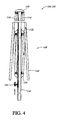
Figure 4 is a cross-sectional view of the embodimentFigure 3 , the frame assembly and umbrella being shown in a closed or collapsed configuration; -
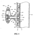
Figure 5 is a vertical cross-sectional view of another embodiment of an actuating and securing mechanism for an umbrella; -
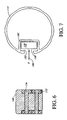
Figure 6 is a cross-sectional view taken atsection plane 6--6 inFigure 5 of a sliding member with rollers, the sliding member located in a receiving area of a support pole illustrated schematically inFigure 7 ; -
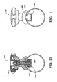
Figure 8 is a side view of one embodiment of the actuating and securing mechanism ofFigure 5 ; -
Figure 9 is a vertical cross-section view of the actuation assembly ofFigure 2 ; -
Figure 10 is a cross-sectional view ofFigure 9 taken atsection plane 10--10; -
Figure 11 is a cross-sectional view ofFigure 9 taken atsection plane 11--11; -
Figure 12 is a vertical cross-section similar toFigure 9 showing another configuration of the actuating and securing mechanism; -
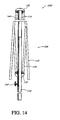
Figure 13 is a vertical cross-sectional view of another embodiment of a frame assembly for an umbrella in an open or erect configuration; and -
Figure 14 is a vertical cross-sectional view of the embodiment illustrated byFigure 13 in a closed or collapsed configuration. -
Figure 1 illustrates in perspective view one embodiment of an umbrella orumbrella assembly 100. Theumbrella assembly 100 is illustrated inFigures 1 and3 in an open orerect configuration 106 that provides shade and shelter from the elements to users of theumbrella assembly 100. Theumbrella assembly 100 can also be positioned in a closed or collapsedconfiguration 108 as illustrated in partial section view inFigure 4 . - In this embodiment, the
umbrella assembly 100 comprises aframe assembly 102 and acanopy 104 which is attached to and supported by theframe assembly 102. Thecanopy 104 can comprise an at least partially flexible material, such as fabric and/or a plastic film. Thecanopy 104 offers shade protection from incident sunlight, as well as at least partial shelter from the elements, e.g., rain, bird droppings, tree sap, etc. Thecanopy 104 also can comprise materials having weather and sun resistant characteristics to provide extended durability and usage in outdoor settings. Thecanopy 104 also can be provided in an attractive color scheme or pattern and/or with a logo or other design to the user's taste. - The
frame assembly 102 is in this embodiment designed and constructed to raise or open thecanopy 104, as illustrated inFigures 1 and3 , as well as to lower or close the canopy as illustrated inFigure 4 . This aspect provides the advantage that the physical envelope encompassed by theumbrella assembly 100 in theclosed configuration 108 is reduced to thereby facilitate storage, movement and/or packaging for shipment of theumbrella assembly 100. Theframe assembly 102 also provides the ability to conveniently open theumbrella assembly 100 with attachedcanopy 104 when theumbrella assembly 100 is to be used. Several embodiments of theframe assembly 102 will be described with operating characteristics and advantages thereof discussed in greater detail below. - In one embodiment, the
frame assembly 102 of theumbrella assembly 100 comprises a support pole ormember 110. Thesupport pole 110 is configured to support and elevate or extend theumbrella assembly 100 such that theextended canopy 104 can provide a sheltered and shaded region underneath. As discussed further below, thesupport pole 110 can be an assembly of a plurality of components. In some arrangements, thesupport pole 110 is a lower pole of a support pole assembly. In one embodiment, thesupport pole 110 is provided with a mountingend 112 which is adapted for attachment or mounting in place for use of theumbrella assembly 100. The mountingend 112 is a lower end of thesupport pole 110.Figure 1 illustrates that one embodiment of the mountingend 112 is configured for attachment to a pedestal or base 113 which would typically be placed on and rest on the ground, a patio deck, a lawn, or the like. It will be understood that this is simply an illustration of one embodiment of the mountingend 112. In other embodiments, the mountingend 112 is configured for direct attachment or mounting in a patio, to a bracket on a vertically or horizontally extending building surface, or the like. The attachment of the mountingend 112 is in certain embodiments of a permanent or semi-permanent nature and in other embodiments comprises a releasable attachment. The attachment of the mountingend 112 in certain embodiments restrains both translation and rotation of thesupport pole 110. In other embodiments, the mountingend 112 is configured to allow limited rotational movement, e.g., a swiveling type movement. In yet other embodiments, the mountingend 112 is configured to accommodate rotation about multiple axes, e.g., in a pivoting type movement. In yet other embodiments, the attachment of the mounting end can be configured for translational movement, e.g., along a track or rail mount. Thus, it will be understood that the mountingend 112 is provided in certain embodiments to enable theumbrella assembly 100 to be conveniently mounted in place for use of theassembly 100. - The
support pole 110 comprises a generally elongate rigid member which enables theframe assembly 102 to maintain thecanopy 104 in an open or expanded configuration in a position distal from the mountingend 112 where theumbrella assembly 100 can be mounted in place.Figure 1 illustrates one embodiment in which the support pole ormember 110 is substantially straight or linear along the extent of thesupport pole 110. In other embodiments, the support pole ormember 110 comprises both straight or linear portions, as well as curved portions. In yet other embodiments, the support pole ormember 110 is curved substantially along an entire extent of the support pole or member.Figure 1 also illustrates that one embodiment of the support pole ormember 110 can be arranged in a substantially vertical orientation. However, in other embodiments, the support pole ormember 110 can be arranged in an angled or diagonal orientation depending on the requirements of particular applications. - The
frame assembly 102, including the component parts thereof, for example, including the support pole ormember 110, preferably comprise relatively strong lightweight materials having suitable durability and weather resistant properties for the particular application of theumbrella assembly 100. Suitable materials for theframe assembly 102 can include but are not limited to light gauge corrosion resistant steels, aluminum alloys, titanium alloys, wood, plastics, carbon fiber materials, and/or other relatively high strength weather resistant materials as are well known. Appropriate selection of materials for construction of theframe assembly 102 can be at least partially dictated in particular applications by the desired aesthetic properties of theumbrella assembly 100, including theframe assembly 102. For example, in certain applications, desirable aesthetic qualities of theumbrella assembly 100 may indicate the use of finished or unfinished wood as components of theframe assembly 102, although other components may offer certain advantages in strength, weight, cost, or other characteristics. Thus, it will be appreciated that the materials selected for construction of theumbrella assembly 100 can vary in different applications and the selection of an appropriate material will be readily apparent to one of ordinary skill considering the disclosure and illustration of the subject application and the requirements of a particular application. - As illustrated in
Figure 1 , theframe assembly 102 also comprises acanopy support structure 120. In some embodiments as discussed below, thecanopy support structure 120 is a canopy support frame. Thecanopy support structure 120 extends generally radially outward from a central axis of theumbrella assembly 100. In one implementation, the central axis is defined by a major or longitudinal axis of the support pole ormember 110. Thecanopy support structure 120 is articulated such that thecanopy support structure 120 can extend into an open or expandedconfiguration 106 as illustrated inFigure 1 and can further be collapsed or closed to aconfiguration 108, for example, as illustrated inFigure 4 . -
Figures 1 and8-12 illustrate that theumbrella assembly 100 includes an actuating or expansion assembly or handle 140'. A user can open and close theumbrella assembly 100 and thecanopy support structure 120 in this embodiment by actuating the actuating assembly 140'. The actuating handle 140' enables a user to apply force by hand to release theframe assembly 102 from a secured or stowed configuration. When theframe assembly 102 is released, theumbrella assembly 100 can be opened or closed. - The actuating assembly 140' is of a simple mechanical structure, yet is able to open and close the
umbrella assembly 100 with a relatively low force. This is a significant advantage for smaller and weaker users. The actuating assembly 140' avoids complex mechanisms and thus reduces susceptibility to foreign material contamination and corrosion. Theactuating assembly 140 also offers aesthetic advantages which will be described in greater detail along with the operational advantages of the actuating assembly 140' following a more detailed description of the component structure of the assembly 140'. -
Figures 2-7 illustrate anactuating assembly 140 that is one variation of the actuating assembly 140'. Theactuating assembly 140 enables repositioning of a hand-gripping portion thereof without disengaging africtional engagement 180, as discussed below. -
Figure 2 illustrates in side section view one embodiment of aframe assembly 102 in greater detail. As previously noted, in one embodiment, theframe assembly 102 includes a support pole ormember 110 configured to support and extend thecanopy 104 of theumbrella assembly 100. Theframe assembly 120 can be raised or lowered via hand manipulation of theactuating assembly 140. In this embodiment, anupper pole 114 is provided that is vertically translatable relative to thesupport pole 110. In one embodiment, theupper pole 114 fits with thesupport pole 110 in a male-female arrangement which inhibits transverse translation of theupper pole 114 relative to thesupport pole 110 while permitting longitudinal or sliding movement, e.g., along a major or longitudinal axis thereof. In one embodiment, the support pole ormember 110, together with theupper pole 114 define anengagement region 118 within which the twopoles Figures 1 and3 , theengagement region 118 is substantially straight or linear. In other embodiments, thesupport pole 110 andupper pole 114 can have a cooperating curvature such that acurved engagement region 118 still permits longitudinal sliding between the twopoles - The
frame assembly 102 further comprises a first hub orjunction 130, a second hub orjunction 132, and a third hub orjunction 124. The first hub orjunction 130 is attached to theupper pole 114 in one embodiment, e.g., adjacent an upper end thereof. In one embodiment, thefirst hub 130 is mounted to theupper pole 114 such that both translation and rotation of thefirst hub 130 are restrained relative to theupper pole 114. In another embodiment, at least one of rotation and translation of thefirst hub 130 relative to theupper pole 114 is restrained. In another embodiment, one of rotation and translation of thefirst hub 130 relative to theupper pole 114 is restrained. In some arrangements, thefirst hub 130 is an upper hub that is coupled with a plurality of ribs in one embodiment. - The second hub or
junction 132 is coupled with, e.g., mounted to, an upper end of thesupport pole 110. The upper end of thesupport pole 110 is an end opposite of the mountingend 112. In this embodiment, thesecond hub 132 also is attached to restrain at least one of, e.g., both of, translation and rotation of thesecond hub 132 relative to thesupport pole 110. In one embodiment, thesecond hub 132 is a middle hub that is coupled with a lower pole, which can be thesupport pole 110. - As discussed further below, the third hub or
junction 134 is coupled with one or more ribs of thecanopy support structure 120. Thethird hub 134 also can be coupled with thesupport pole 110. As discussed further below, thethird hub 134 can be arranged to slide along a portion of thesupport pole 110 in one embodiment. Thethird hub 134 can also be located at a position intermediate thesecond hub 132 and the mountingend 112 of thesupport pole 110. Thus, in one embodiment, thefirst hub 130 is arranged at one end of theumbrella assembly 100 opposite from the mountingend 112. Thesecond hub 132 andthird hub 134 are positioned intermediate thefirst hub 130 and the mountingend 112, with thesecond hub 132 being further interposed between thefirst hub 130 and thethird hub 134. - The
third hub 134 can be coupled with thesupport pole 110 such that rotation of thethird hub 134 relative to thesupport pole 110 is restrained. Preferably, the coupling of thethird hub 134 with thesupport pole 110 permits vertical movement, e.g., along the longitudinal axis of thesupport pole 110. This arrangement restrains horizontal or transverse translation of thethird hub 134 relative to thesupport pole 110. Thethird hub 134 is attached to thesupport pole 110 in a manner which allows controlled translation of thethird hub 134 longitudinally or along a major axis of thesupport pole 110. - As previously mentioned, in one embodiment, the
umbrella assembly 100 can be opened and/or closed via manipulation of theactuating assembly 140. In one embodiment, theactuating assembly 140 is configured to be slidably interconnected with the support pole ormember 110. Theactuating assembly 140 is further interconnected with thefirst hub 130 via anactuating member 144. In one arrangement, the actuatingmember 144 comprises an upper pole of a support pole assembly. In this embodiment, longitudinal force or force applied along the major axis of thesupport pole 110 to theactuating assembly 140 is communicated via the actuatingmember 144 to thefirst hub 130. A longitudinal force applied to theactuating assembly 140 in a direction away from thefirst hub 130 along thesupport pole 110 or generally in a direction towards the mountingend 112, as indicated by the downwardly pointing arrow inFigure 3 , applies a tension force to thefirst hub 130 inducing thefirst hub 130 to follow the motion of theactuating assembly 140. An opposite force applied to theactuating assembly 140 applies a compressive force to the actuatingmember 144, which transfers the force to thefirst hub 130 to induce theframe assembly 102 to collapse or close as illustrated inFigure 4 . - In one embodiment, the actuating
member 144 comprises a generally elongate rigid or semi-rigid member interconnecting theactuating assembly 140 and thefirst hub 130. However, in other embodiments the actuatingmember 144 acts in tension and a cable is used to interconnect theactuating assembly 140 and thefirst hub 130. As in certain embodiments, theactuating assembly 140 and actuatingmember 144 connected to thefirst hub 130 operate in tension. These embodiments avoid the bending and binding of rigid or semi-rigid members of structures in which an elongate member is subjected to compression forces. Such mechanisms employing compressive forces also typically preclude the utilization of cables, ropes, and chains as these are typically not capable of effectively transferring a compression force. - A further advantage of certain embodiments of the
umbrella assembly 100 andframe assembly 102 thereof are that gravity and the weight of theumbrella assembly 100 can assist in at least one of the opening and closing theumbrella assembly 100. More particularly, when embodiments of theumbrella assembly 100 are arranged in a generally vertical orientation, e.g., when thesupport pole 110 is arranged generally vertically, gravitational forces act upon the mass of the components of theumbrella assembly 100, urging these components downward. For example, as illustrated inFigure 4 , a limited restraining force can be applied along the longitudinal extent of thesupport pole 110 to control the closing of theumbrella assembly 100 with gravity assisting the collapse of theframe assembly 102. In use, a force less than the weight of the user may be applied to theactuating assembly 140 in a generally downward direction to induce the opening or erection of theumbrella assembly 100. Preferably, raising or opening of theumbrella assembly 100 requires relatively little muscular exertion as the user can simply use a portion of their body weight to apply a generally downward force to theactuating assembly 140, e.g., by leaning on the actuator assembly. This facilitates use of a relativelylarge umbrella assembly 100 by those of relatively small stature and/or limited strength or by the physically impaired. - Further advantages to the opening and closing of the
umbrella assembly 100 are provided by the arrangement of thecanopy support structure 120. More particularly, in one embodiment, thecanopy support structure 120 comprises a plurality of mounting ribs or staves 122 which are interconnected with a corresponding plurality offirst erection members 124 andsecond erection members 126. Each of the mounting ribs or staves 122 and the first andsecond erection members umbrella assembly 100, e.g., of theframe assembly 102. The mounting ribs or staves 122 are positioned generally at an upper extent of thecanopy support structure 130 to support attachment points for thecanopy 104. The mounting ribs or staves 122 extend substantially the radial extent or to the peripheral edge of thecanopy 104 in one embodiment. Proximal ends of the mountingribs 122 can be pivotably connected or nested in thefirst hub 130. Distal ends of thefirst erection members 124 can be pivotably connected along intermediate points to the mountingribs 122. Proximal ends of thefirst erection members 124 can be pivotably connected or nested in the third hub orjunctions 134. Distal ends of thesecond erection members 126 can be pivotably connected to intermediate points of thefirst erection members 124 with proximal ends of thesecond erection members 126 being pivotably connected or nested with thesecond hub 132 in some embodiments. - Thus, the
first hub 130 can be controllably moved longitudinally relative to thesecond hub 132 via manipulation of theactuating assembly 140 and the actuatingmember 144. Thethird hub 134 is free to slide longitudinally relative to thesecond hub 132, e.g., along thesupport pole 110, in one embodiment. The mountingribs 122 and the first andsecond erection members third hubs third hubs second hub 132 will close or collapse, or open or raise respectively thecanopy support structure 120 and the attachedcanopy 104. - Appropriate selection of the relative lengths of the mounting
ribs 122 and first andsecond erection members ribs 122 andfirst erection members 124 to which thefirst erection members 124 andsecond erection members 126 are respectively interconnected, provide mechanical advantage. Providing mechanical advantage can further reduce the force required to be applied to theactuating assembly 140 to raise or lower theumbrella assembly 100. As previously noted, in some embodiments, gravity can assist in at least one of opening and closing of an umbrella, e.g., theumbrella assembly 100. In other embodiments, theumbrella assembly 100 defines a substantially balanced or weight neutral configuration. For example, the relative weight, placement, and mechanical leverage ratios of the components of theumbrella assembly 100 can be arranged such that gravity induces theassembly 100 to open or to close. Theumbrella assembly 100 can also be constructed such that weight loads are substantially balanced such that, absent an opening or closing applied force, theumbrella assembly 100 is balanced and not induced to either close or open. - In one embodiment, an
umbrella assembly 100 of an approximate open height of one hundred and fifteen inches (approximately 292 centimeters) and having a canopy diameter of approximately thirteen feet (approximately 396 centimeters) can be readily opened or closed by an ordinary user (e.g., one of average strength). In one embodiment, theumbrella assembly 100 can have approximate closed height of one hundred and forty inches (approximately 356 centimeters). This is achieved in part by providing mountingribs 122,first erection members 124, andsecond erection members 126 of a suitable configuration. For example, the length of theribs 122 is about eighty inches (about 203 centimeters) in one embodiment. The length of thefirst erection members 124 is about thirty-seven inches (about 94 centimeters) in one embodiment. The length of thesecond erection members 126 is sixteen inches (about 41 centimeters) in one embodiment. Each of thefirst erection members 124 is attached to acorresponding rib 122 at about forty-four inches (about 112 centimeters) from the proximal end of therib 122. Each of thesecond erection members 126 is attached to a correspondingfirst erection member 124 at about twenty-one inches (about 53 centimeters) from the proximal end of thefirst erection member 124. - Other size umbrellas can be constructed that can be easily opened by an ordinary user. For example, in one embodiment the
ribs 122 are constructed with a length that is about equal to two times the length of theerection members 124. In another embodiment, theribs 122 are constructed with a length that is more than two times the length of theerection members 124. In another embodiment, theerection members 124 are constructed with a length that is about equal to two times the length of the erection members 128. In one embodiment, theerection members 124 are constructed with a length that is more than two times the length of theerection members 126. In another embodiment, theribs 122 are constructed with a length that is about equal to four times the length of theerection members 126. In another embodiment, theribs 122 are constructed with a length that is more than four times the length of theerection members 124. - Other arrangements also facilitate umbrella operation by an ordinary user. For example, in one embodiment the
ribs 122 are connected to theerection members 124 by a pivoting joint that is located a distance more than half the length of theribs 122 from the proximal end of theribs 122. In another embodiment, theerection members 124 are connected to theerection members 126 by a pivoting joint that is located a distance more than half the length of theerection member 124 from the proximal end of theerection member 124. In another embodiment, theribs 122 are connected to theerection members 124 by a pivoting joint that is located closer to the distal ends of theribs 122 than to the proximal ends thereof and theerection members 124 are connected to theerection members 126 by a pivoting joint that also is located closer to the distal ends of theerection member 124 that to the proximal ends thereof. -
Figure 4 shows additional components and details of one embodiment of theactuating assembly 140. In one embodiment, theactuating handle 142 is comprised of anactuating handle cover 150 and anactuating handle base 152 which are connected via one ormore fasteners 154. Anelongate shaft 156 passes through theactuating handle base 152 and engages with theactuating assembly base 146, discussed below. Anouter gear 160 is engaged with theactuating handle 142 and aninner gear 162 is engaged with theshaft 156. Aresilient member 164, which in one embodiment is configured as a coil spring, applies preload force that acts on at least one of the outer andinner gears outer gear 160 and theshaft 156 with theinner gear 162 is such that axial movement of the actuating handle 142 relative to theshaft 156 induces the outer andinner gears inner gears actuating handle 142 is communicated to corresponding rotation of theshaft 156. When the outer andinner gears shaft 156. - The end of the
shaft 156 opposite theactuating handle 142 engages with a securingpiece 170 in a spiral thread or cam manner such that rotation of theshaft 156. For example rotation of theactuating handle 142 induces the securing piece to translate radially inward or outward from a surface of thesupport pole 110. The securingpiece 170 fits with radial clearance within areceiver region 148, discussed below, and within arecess 176 of thebase 146. Appropriate rotation of theshaft 156 thus induces the securing piece to translate radially so as to contact the receiver region orcontour 148 of thesupport pole 110 at either an inner or outer location or with clearance in an intermediate position. - When the securing
piece 170 is engaged with thesupport pole 110, africtional engagement 180 is formed between the securingpiece 170 and thepole 110. Thefrictional engagement 180 is arranged generally inwardly with respect to a centerline (e.g., a central or longitudinal axis) of thesupport pole 110. In another embodiment, a frictional engagement could be located outwardly from the centerline of thesupport pole 110. When theshaft 156 is rotated to urge the securingpiece 170 into africtional engagement 180, the securing piece and theshaft 156, actuatinghandle 142, andbase 146 are frictionally engaged with thesupport pole 110 to inhibit sliding or translational movement relative to the pole. - As discussed above, the
actuating assembly 140 is connected with the actuatingmember 144 and with thefirst hub 130. When theactuating assembly 140 is engaged to form thefrictional engagement 180, the configuration of the umbrella assembly 100 (e.g., the degree of opening) is fixed. To release thefrictional engagement 180, theactuating handle 142 is turned to turn theshaft 156 whereby a threaded or cam engagement with the securingpiece 170 laterally translates the securing piece to release thefrictional engagement 180. - One advantage of certain embodiments of the
actuating assembly 140 is that theactuating handle 142 can be moved independently of theshaft 156. More particularly, as previously noted, theactuating handle 142 can be translated laterally or axially along theshaft 156 to engage or disengage the outer andinner gears actuating handle 142 is manipulated to engage thegears shaft 156 can be manipulated to engage or release thefrictional engagement 180. Upon achieving the desired engagement or release of the frictional engagement, theactuating handle 142 can be further manipulated to disengage thegears frictional engagement 180. One example of an aesthetically pleasing symmetric orientation is shown inFigure 8 . This re-arranging of theactuating handle 142 can be achieved without affecting a secured or released configuration of theactuating assembly 140. This provides the advantage that asymmetric or variable mechanical appearances can be eliminated or minimized for various configurations of theumbrella assembly 100. - It will be appreciated that the arrangement of the
actuating handle 142 andshaft 156 with the associated gears 160 and 162 can be adapted to the requirements of particular applications, including whether a pull or push force, e.g., movement away from or towards thesupport pole 110, is required to engage or disengage thegears shaft 156 with the tighteningpiece 170 may be adapted to require relatively small movements or relatively large movements based again on the anticipated application of theumbrella assembly 100 and the capabilities of anticipated users thereof. - In one embodiment, the receiver region or
contour 148 defines an undercutregion 182. The undercutregion 182 provides the advantage of further maintaining the securingpiece 170 andbase 146 within thereceiver region 148. The undercutregion 182 also facilitates arranging frictional engagement at either the inner or outer regions of thereceiver region 148. In one embodiment, the undercutregion 182 describes a generally "H" or "I" shaped contour. In this embodiment, a tension force applied by theshaft 156 as engaged with the securingpiece 170, indicated F156 inFigure 7 is directed substantially perpendicular to thefrictional engagement 180. In other embodiments, the undercutregion 182 of thereceiver region 148 can describe a dovetail, semi-cylindrical, or other undercut contour with corresponding contouring of the engaging surfaces of the securingpiece 170. - Longitudinal or sliding movement of the
base 146 of theactuating assembly 140 is further facilitated by a plurality of rollers orwheels 172. The rollers orwheels 172 are attached via correspondingaxles 174 to the base 145 such that the rollers orwheels 172 are free to rotate to provide a rolling or wheeled contact between the base 146 of theactuating assembly 140 and thereceiver region 148 of thesupport pole 110. Reduced friction in theactuating assembly 140 is also facilitated via placement of abushing 166 between theshaft 166 and theactuating handle 142. - The mechanical advantage provided by the
umbrella support assembly 120 also reduces the throw or distance which theactuating assembly 140 needs to move to raise or lower the umbrella. -
Figure 7 shows additional details of one configuration of theactuating handle 142 and asupport pole 110. Thesupport pole 110 comprises a plurality of longitudinally extending ribs or flutes 188. The dimensions and contours of the ribs orflutes 184 are comparable to the dimensions of thereceiver region 148 and the actuatingmember 144 positioned therein. Thus, in this embodiment, thesupport pole 110 presents a more uniform consistent appearance about a circumference thereof which reduces the visual impact of the mechanical component of the actuatingmember 144. The actuating handle 142 in this embodiment is configured as a generally smoothly curved oblong or oval shape which can be arranged in a generally vertical orientation so as to present bilateral symmetry about a vertical axis to present an aesthetically balanced view to a user of theumbrella assembly 100. However, theactuating handle 142 also exhibits asymmetry about a horizontal or transverse axis (in the position illustrated) to present a visual indication of the orientation of theactuating handle 142, as well as to provide an enhanced grasping surface to facilitate hand manipulation of theactuating assembly 140. -
Figures 8-12 illustrate further details of the actuating assembly 140' suitable for use with theumbrella assembly 100. The embodiment of actuating assembly 140' is similar in certain aspects with the previously described embodiments ofassembly 140. Similar component parts and operational characteristics will not be repeated in detail for brevity and ease of understanding. In this embodiment, the actuating handle 142' differs by being continuously engaged with a shaft 156'. In this embodiment, the actuating assembly 140' comprises an actuating handle 142' configured for hand manipulation by a user. The actuating handle 142' can be an actuating handle. The external surface of the actuating handle 142' is preferably configured in an ergonomic manner to facilitate comfortable grasping by a user and in certain embodiments has bilateral symmetry to facilitate usage by either a right handed or left handed user. In certain embodiments, the actuating handle 142' also exhibits an asymmetric contour or characteristic to indicate the orientation of the actuating handle 142'. This provides functional and aesthetic advantages to theumbrella assembly 100 which will be described in greater detail below following a more detailed description of the component parts and operating of the actuating assembly 140' with the actuating handle 142'. - In this embodiment, the actuating assembly 140' also comprises a base 146'. The base 146' is configured to engage with the
support pole 110 along a receiver region orcontour 148 thereof (seeFigures 7 and9 ). The receiver region orcontour 148 defines an elongate channel extending longitudinally or along a major axis of thesupport pole 110. The base 146' engages cooperatively with the receiver region orcontour 148 of thesupport pole 110 to be retained therein in a manner allowing controlled longitudinal or sliding movement along thesupport pole 110. As previously noted, the actuatingmember 144 is between, and is connected in one embodiment to, the actuating assembly 140' and thefirst hub 130. Thus, user force applied to the actuating handle 142' induces the base 146' as well as the actuatingmember 144 to slide or longitudinally translate along the receiver region orcontour 148 of thesupport pole 110. In this embodiment, the actuating member 144' also extends within thereceiver region 148. - The actuating assembly 140' does not need to be selectively coupled or decoupled from the actuating handle 142' with the shaft 156'. The embodiment of actuating assembly 140' offers even greater simplicity in construction and manufacture as well as simplified use.
- In a similar manner to that previously described for the
assembly 140, in this embodiment, rotation of the actuating handle 142' induces the shaft 156' to corresponding rotation. The shaft 156' is threaded together with or engaged in a cam type arrangement with a securingstructure 170. Rotation of the actuating handle 142' induces the shaft 156' to turn to thereby induce the securingstructure 170 to translate laterally inward or outward within thereceiver region 148. This engages or disengages a frictional engagement 180' (seeFigures 10 and12 ) depending on the direction of movement of the actuating handle 142' and the particular configuration of the actuating assembly 140'. The actuating assembly 140' can thus secure theumbrella assembly 100 in place or be utilized to achieve a desired opening/closing configuration as previously described. - The actuating assembly 140' also differs in having an alternative configuration of engagement between the actuating handle base 152' and the
receiver region 148 of thesupport member 110. In one embodiment, the actuating handle base 152' comprises a low-friction coating orlayer 188 arranged on outer surfaces of the actuating handle base 152' and more particularly to region of engagement between the actuating handle base 152' and thereceiver region 148. The actuating handle base 152' can have, but does not require, rollers or axles. The actuating assembly 140' of this embodiment thus offers further additional simplification in structure and manufacture as compared to theassembly 140. Appropriate selection of an embodiment of anactuating assembly 140, 140' can be readily made by one of ordinary skill based in part on the intended application of theumbrella assembly 100 and the desired price point of the final product. - The actuating assembly 140' further differs in having a different configuration of the actuating handle 142'. In this embodiment, the actuating handle 142' describes generally a radially symmetrical structure. In one embodiment, the actuating handle 142' is generally configured as an equilateral triangle with rounded or flattened vertices. The actuating handle 142' can thus exhibit symmetry about a vertical or a horizontal axis independent of the particular orientation of the actuating handle 142'. In yet other embodiments, the actuating handle 142' is generally circular in contour and can include flutes or knurling as additional ergonomic and/or aesthetic enhancements. The actuating handle 142' can also be provided with distinctive lettering, coloring, or other designations to indicate the orientation of the actuating handle 142' to facilitate user actuation of the actuating handle 142' to a desired position. Thus, in these embodiments, the actuating handle 142' exhibits generally radial symmetry such that no usual operational orientation of the actuating handle 142' presents a distinctive unpleasing asymmetry.
-
Figures 13 and14 illustrate in side section view another embodiment of anumbrella assembly 200 shown in anopen configuration 106 inFigure 13 and in aclosed configuration 108 inFigure 14 . The embodiment illustrated inFigures 13 and14 shares many similarities in operation and component parts with the previously described embodiments of theumbrella assembly 100. Similar operational characteristics and components will not be described in detail for brevity and ease of understanding. - The embodiment of an
umbrella assembly 200 illustrated inFigures 13 and14 differs in the construction of a canopy support structure 120' that need not include three hubs. For example, in one embodiment, the canopy support structure 120' can be constructed with thethird hub 134 and associatedsecond erection members 126. Thus, in this embodiment, afirst hub 130 is pivotably engaged with a plurality of mounting ribs or staves 122 configured for attachment to and support of anumbrella canopy 104. In this embodiment, thesecond hub 132 is similarly pivotably connected with a corresponding plurality offirst erection members 124 which are pivotably connected at an opposite end to corresponding mountingribs 122. Anupper pole 114 is similarly coupled with thesupport pole 110 along anengagement region 118 whereby slideable or longitudinal movement between theupper pole 114 and thesupport pole 110 is accommodated. In a similar manner to theumbrella assembly 100 embodiments previously described, an actuating assembly (e.g., theactuating assembly 140 or the actuating assembly 140') engages with an actuatingmember 114 to couple with thefirst hub 130. Appropriate force applied longitudinally along thesupport pole 110 can draw thefirst hub 130 into adjacency with thesecond hub 132, which is fixed in elevation, so as to erect theumbrella assembly 200. An opposing force can be applied to the actuating assembly (e.g., to theactuating assembly 140 or the actuating assembly 140') to allow thefirst hub 130 to be separated from thesecond hub 132 to achieve theclosed configuration 108, for example, as illustrated inFigure 14 . - The embodiments of
umbrella assembly 200 offer the advantage of reduced parts count and even simpler mechanical construction than the previously described embodiments of theumbrella assembly 100. The mechanical advantage provided by theumbrella assembly 200, for example, in opening and closing operations of theassembly 200 is lower than in the previously described embodiments of theumbrella assembly 100. Thus, theumbrella assembly 200 is more suitable where the weight loading of theumbrella 200 is lower or in applications wherein the anticipated physical capabilities of users are sufficient for easy operation of theumbrella assembly 200 with the lower mechanical advantage of this mechanism. - Thus, the various embodiments previously described of
umbrella assemblies umbrellas assemblies - Although the above disclosed embodiments of the present teachings have shown, described and pointed out the fundamental novel features of the invention as applied to the above-disclosed embodiments, it should be understood that various omissions, substitutions, and changes in the form of the detail of the devices, systems and/or methods illustrated may be made by those skilled in the art without departing from the scope of the present teachings. Consequently, the scope of the invention should not be limited to the foregoing description but should be defined by the appended claims.
- This disclosure includes all permutations of the independent claims with their dependent claims.
Claims (15)
- An umbrella (100), comprising: a support pole assembly comprising: a lower pole (110) having a lower end and an upper end; an upper pole (114) vertically translatable relative to the lower pole (110); a canopy support frame (120) comprising: an upper hub (130) coupled with the upper pole (114) and with a plurality of ribs (122); and an actuating handle (142) coupled with the upper pole (114) and translatable relative to the lower pole (110) so that, when the actuating handle (142) is raised, the upper pole (114) and the upper hub (130) are raised causing the canopy support frame (120) to close; distal ends of first erection members (124) pivotably connected along intermediate points to the ribs (122), proximal ends of the first erection members (124) pivotably connected in a third, lower hub (134); the umbrella being characterised in that it further comprises distal ends of second erection members (126) pivotably connected to intermediate points of the first erection members (124) with proximal ends of the second erection members (126) pivotably connected with a second, intermediate hub (132).
- The umbrella (100) of Claim 1, further comprising a selection of relative lengths of the ribs (122) and first (124) and second (126) erection members, as well as a location of corresponding intermediate points of the ribs (122) and first erection members (124) to which the first erection members (124) and second erection members (126) are respectively interconnected to provide mechanical advantage to reduce a force required to be applied to the actuating handle (142) to raise or lower the umbrella (100).
- The umbrella (100) of Claim 2, wherein said selection of lengths and location produce a weight neutral configuration of the umbrella, such that weight loads of the umbrella (100) are substantially balanced such that, absent an opening or closing applied force, the umbrella (100) is balanced and not induced to either close or open.
- The umbrella (100) of Claim I or Claim 2, wherein in use the upper (130) and third (134) hubs are moved relative to the intermediate hub (132) to close or open the umbrella (100).
- The umbrella (100) of any of the preceding claims, wherein the actuating handle (142) is coupled with the support pole assembly for translation along an axis parallel to a longitudinal axis of the support pole assembly.
- The umbrella (100) of any of the preceding claims, wherein the actuating handle (142) has a first position relative to the support pole assembly in which the actuating handle (142) is spaced from a side surface of the support pole assembly to permit vertical movement of the actuating handle (142), said vertical movement raising or lowering at least one of the hubs (130,132,134), and a second position relative to the support pole assembly in which the actuating handle (142) frictionally engages a side surface of the support pole assembly to inhibit vertical movement of the actuating handle (142).
- The umbrella (100) of Claim 6, wherein the actuating handle (142) comprises a hand-gripping portion (142) and a frictional surface (180) moveable into engagement with the side surface of the support pole assembly.
- The umbrella (100) of Claim 7, wherein the actuating handle (142) is configured such that rotation of the hand-gripping portion (142) causes the frictional surface (180) to move transversely to the support pole assembly into engagement with the support pole assembly and out of engagement with the support pole assembly.
- The umbrella (100) of Claims 7 or 8, wherein the hand-gripping portion (142) is symmetrical about an axis extending transverse to the support pole.
- The umbrella (100) of any of Claims 7 to 9, wherein the hand-gripping portion (142) can be moved independently of the frictional surface (180).
- The umbrella (100) of any of Claims 7 to 10, wherein the hand-gripping portion (142) can be manipulated to couple or decouple movement of the hand-gripping portion (142) and the frictional surface (180).
- The umbrella (100) of Claim 1, wherein the second hub (132) maintains a constant elevation as the upper hub (130) is raised.
- The umbrella (100) of any of Claims 1 to 12, further comprising an elongate member (144) having a lower end coupled with the actuating handle (142) and an upper end coupled with the upper hub (130) such that vertical movement of the actuating handle (142) is transferred through the elongate member (144) to the upper hub (130) causing vertical movement of the upper hub (130).
- The umbrella (100) of Claim 13, wherein the support pole assembly comprises an elongate channel (148) in which the elongate member (144) moves as the actuating handle (142) moves.
- The umbrella (100) of Claim 14, further comprising at least one roller (172) positioned between the elongate member (144) and the elongate channel (148).
Applications Claiming Priority (2)
| Application Number | Priority Date | Filing Date | Title |
|---|---|---|---|
| CNU2004201079760U CN2737198Y (en) | 2004-11-04 | 2004-11-04 | Device for opening and closing umbrella |
| US11/216,535 US7963293B2 (en) | 2004-11-04 | 2005-08-31 | Umbrella opening and closing device |
Publications (2)
| Publication Number | Publication Date |
|---|---|
| EP1654952A1 EP1654952A1 (en) | 2006-05-10 |
| EP1654952B1 true EP1654952B1 (en) | 2014-10-22 |
Family
ID=35874585
Family Applications (1)
| Application Number | Title | Priority Date | Filing Date |
|---|---|---|---|
| EP05255342.7A Active EP1654952B1 (en) | 2004-11-04 | 2005-09-01 | Umbrella opening and closing device |
Country Status (3)
| Country | Link |
|---|---|
| US (1) | US7963293B2 (en) |
| EP (1) | EP1654952B1 (en) |
| CN (1) | CN2737198Y (en) |
Families Citing this family (33)
| Publication number | Priority date | Publication date | Assignee | Title |
|---|---|---|---|---|
| CN2737198Y (en) | 2004-11-04 | 2005-11-02 | 马准安 | Device for opening and closing umbrella |
| WO2008030895A1 (en) | 2006-09-05 | 2008-03-13 | Oliver Joen-An Ma | Shade structures such as umbrellas |
| CA2681195C (en) * | 2007-06-04 | 2014-10-14 | Glatz Ag | Free-arm canopy |
| US7438077B1 (en) * | 2007-08-10 | 2008-10-21 | Wilson Robert J | Sleeve-actuated umbrella |
| EP2203684B1 (en) * | 2007-08-24 | 2020-08-05 | Fis Design, LLC | Heater |
| US8251078B2 (en) * | 2009-04-28 | 2012-08-28 | Oliver Joen-An Ma | Umbrella handle |
| CN101874671B (en) * | 2009-04-28 | 2011-12-28 | 马准胜 | Double-lower nest automatic umbrella |
| DE202010003954U1 (en) * | 2010-03-19 | 2011-08-01 | Günter Kaltenbach | Shade and roof |
| CN101779853B (en) * | 2010-03-19 | 2012-05-23 | 翟毅 | Ultraviolet ray and infrared ray preventing biconvex umbrella |
| US8127780B2 (en) * | 2010-05-17 | 2012-03-06 | Benson Tung | Telescopic sunshade |
| US8499775B1 (en) * | 2012-02-10 | 2013-08-06 | Joen-Shen Ma | Leverage-based large-sized umbrella |
| US20130291910A1 (en) * | 2012-05-07 | 2013-11-07 | Doyle Group Co. Ltd. | Gear-Type Umbrella Runner |
| USD813524S1 (en) * | 2013-11-20 | 2018-03-27 | Active Leisure Inc. | Cantilever umbrella stand |
| US10078856B2 (en) | 2016-05-09 | 2018-09-18 | Shadecraft, Inc. | Mobile computing device control of shading object, intelligent umbrella and intelligent shading charging system |
| US9655416B1 (en) | 2014-05-13 | 2017-05-23 | Dougan H. Clarke | Crank handle positioning assembly for an umbrella |
| US10327521B2 (en) | 2015-05-22 | 2019-06-25 | Armen Sevada Gharabegian | Intelligent shading objects |
| US10159316B2 (en) | 2016-05-09 | 2018-12-25 | Shadecraft, Inc. | Intelligent shading charging systems |
| US10250817B2 (en) | 2016-05-09 | 2019-04-02 | Armen Sevada Gharabegian | Shading object, intelligent umbrella and intelligent shading charging system integrated camera and method of operation |
| US10455395B2 (en) | 2016-05-09 | 2019-10-22 | Armen Sevada Gharabegian | Shading object, intelligent umbrella and intelligent shading charging security system and method of operation |
| US10912357B2 (en) | 2016-05-09 | 2021-02-09 | Shadecraft, LLC | Remote control of shading object and/or intelligent umbrella |
| US10813422B2 (en) | 2016-05-09 | 2020-10-27 | Shadecraft, Inc. | Intelligent shading objects with integrated computing device |
| US10016033B2 (en) | 2016-05-31 | 2018-07-10 | Dee Volin | Adjustable canopy umbrella with auditory pin locking and centering system |
| US10368617B2 (en) | 2016-10-25 | 2019-08-06 | ZHUN-AN Ma | Umbrella assembly set up devices |
| US10349493B2 (en) | 2017-07-07 | 2019-07-09 | Shadecraft, Inc. | Artificial intelligence (AI) computing device with one or more lighting elements |
| CN210299842U (en) * | 2019-04-26 | 2020-04-14 | 浙江永强集团股份有限公司 | Sliding assembly of umbrella |
| CN110250683A (en) * | 2019-06-10 | 2019-09-20 | 江苏腾魄休闲用品有限公司 | A kind of hand push parasols |
| US10959500B1 (en) | 2020-02-25 | 2021-03-30 | Richard Holbrook | Umbrella |
| US10881176B1 (en) | 2020-02-25 | 2021-01-05 | Richard Holbrook | Umbrella |
| USD899070S1 (en) | 2020-02-25 | 2020-10-20 | Richard Holbrook | Umbrella |
| USD899069S1 (en) | 2020-02-25 | 2020-10-20 | Richard Holbrook | Umbrella |
| USD899762S1 (en) | 2020-02-25 | 2020-10-27 | Richard Holbrook | Umbrella |
| USD899761S1 (en) | 2020-02-25 | 2020-10-27 | Richard Holbrook | Umbrella |
| USD909042S1 (en) | 2020-06-19 | 2021-02-02 | Richard Holbrook | Umbrella hub system |
Family Cites Families (67)
| Publication number | Priority date | Publication date | Assignee | Title |
|---|---|---|---|---|
| US620815A (en) * | 1899-03-07 | Umbrella | ||
| US521222A (en) * | 1894-06-12 | Self-opening umbrella | ||
| US229685A (en) * | 1880-07-06 | Umbrella | ||
| US776352A (en) | 1904-06-09 | 1904-11-29 | Christopher Godlieb Rogers | Umbrella. |
| US928169A (en) * | 1909-02-09 | 1909-07-13 | William B Morrell | Umbrella. |
| US1001076A (en) * | 1910-10-20 | 1911-08-22 | John Charles Redford | Umbrella. |
| US1207649A (en) * | 1916-04-03 | 1916-12-05 | Richard Martin South | Umbrella. |
| US1712430A (en) * | 1927-09-12 | 1929-05-07 | Giszczynski Stanley | Umbrella runner |
| DE580503C (en) | 1931-10-20 | 1933-07-12 | Bremshey & Co | Large umbrella |
| US1908453A (en) * | 1932-01-14 | 1933-05-09 | Frank Maier | Umbrella |
| US2168188A (en) * | 1935-11-23 | 1939-08-01 | Bernhard Hans | Collapsible umbrella |
| US2185466A (en) * | 1939-06-05 | 1940-01-02 | Bernard J Jostes | Umbrella |
| US2474516A (en) * | 1945-02-26 | 1949-06-28 | Troy Sunshade Company | Tractor umbrella |
| US2507919A (en) * | 1948-03-25 | 1950-05-16 | Frank J Mazzeo | Umbrella |
| US2705967A (en) * | 1952-01-08 | 1955-04-12 | Rosenkaimer Gmbh | Self opening umbrella |
| US2661752A (en) * | 1952-10-15 | 1953-12-08 | Internat Umbrella Supply Co In | Garden umbrella |
| US2860647A (en) * | 1956-09-10 | 1958-11-18 | Negri Adolph | Umbrella and a replaceable rib therefor |
| US3016910A (en) * | 1957-08-01 | 1962-01-16 | Rosenkaimer Gmbh | Self-opening umbrella |
| US2906277A (en) * | 1957-12-26 | 1959-09-29 | Finkel Umbrella Frame Company | Self-opening umbrellas |
| US3672381A (en) * | 1969-08-19 | 1972-06-27 | Nobutoshi Kida | Collapsible umbrella capable of automatic opening |
| DE2226754A1 (en) * | 1972-06-02 | 1973-12-20 | Bremshey Ag | SELF-CLOSING UMBRELLA |
| DE2535634C2 (en) * | 1975-08-09 | 1984-07-05 | Kortenbach & Rauh Kg, 5650 Solingen | Umbrella with roof poles that can be shortened at least twice |
| US4144900A (en) * | 1976-08-20 | 1979-03-20 | Ernst Kinski | Umbrella |
| JPS5347950U (en) * | 1976-09-20 | 1978-04-22 | ||
| JPS58163306A (en) * | 1982-03-19 | 1983-09-28 | 木田 信敏 | Umbrella equipped with oval canopy part |
| JPS58163304A (en) * | 1982-03-19 | 1983-09-28 | 木田 信敏 | Umbrella equipped with oval canopy part |
| FR2554490B3 (en) | 1983-11-03 | 1986-01-24 | Bottier Yves | PROTECTION AGAINST WEATHER OR SUN |
| US4697606A (en) * | 1985-11-01 | 1987-10-06 | Ma Mark J S | Cranked patio umbrella featuring cranked tilt |
| US4763679A (en) * | 1987-07-08 | 1988-08-16 | The Quaker Oats Company | Toy umbrella |
| IT1232369B (en) | 1989-04-10 | 1992-01-28 | Settembrini Edoardo Presicce L | UMBRELLA OPENING AND CLOSING DEVICE |
| US5036872A (en) * | 1990-01-03 | 1991-08-06 | Yueh Huang | Self-opening and self-closing umbrella |
| DE9113211U1 (en) * | 1991-02-27 | 1992-04-02 | Becher Textil & Stahlbau Gmbh | |
| US5564453A (en) * | 1992-10-19 | 1996-10-15 | Steiner; Walter | Apparatus for stationary screening |
| RO115686B1 (en) | 1994-11-09 | 2000-05-30 | Becher Textil & Stahlbau Gmbh | Shade, especially stand-up shade |
| US5483985A (en) * | 1994-11-15 | 1996-01-16 | Yu; Shu-Chun | Fully automatic and simplified control structure |
| NL9500219A (en) | 1995-02-06 | 1996-09-02 | Hendrikus Gerardus Coenen | Parasol (sun shade, umbrella) |
| CN1148950A (en) * | 1995-04-25 | 1997-05-07 | 迈阿密金属产品股份有限公司 | Umbrella frame |
| US5640984A (en) * | 1995-09-12 | 1997-06-24 | Dubunsky; Emanuel | Special fold-up umbrella having rib and frame design for easier opening and closing of umbrella, and two canopies designed to stabilize the ribs and vent the air |
| US5617888A (en) * | 1996-06-20 | 1997-04-08 | Wu; Nick | Garden umbrella with specially drilled pulley cord guide and retainer means in wood pole for maintaining pulley cord |
| GB2319958A (en) * | 1996-12-03 | 1998-06-10 | Yoan Tang | Umbrella selectively foldable to collect rainwater |
| US5842493A (en) * | 1997-06-13 | 1998-12-01 | Yakubisin; Michael J. | Windproof umbrella having an improved rib linkage system |
| US6095169A (en) * | 1997-12-31 | 2000-08-01 | Fu Tai Umbrella Works, Ltd. | Automatic umbrella having rib assembly formed with light grooved rib reinforced resilient rib |
| US5884645A (en) * | 1998-03-03 | 1999-03-23 | Chen; Wu-Hsiung | Collapsible sunshade |
| TW391201U (en) * | 1998-04-24 | 2000-05-21 | You Ching Chiuan | Improved umbrella rib |
| US6082383A (en) * | 1998-07-28 | 2000-07-04 | Wilson; Robert Joe | Umbrella with actuator sleeve for manual and automatic operation |
| US6039063A (en) * | 1998-11-20 | 2000-03-21 | Fu Tai Umbrella Works, Ltd. | Multiple-fold windproof umbrella for preventing sagging of umbrella cloth |
| US6196244B1 (en) * | 1999-01-19 | 2001-03-06 | Joseph R. Haddad | Configurable umbrella |
| TW405351U (en) * | 1999-10-08 | 2000-09-11 | Jang Jen Man | Improvement of single stem umbrella extending structure |
| US6374840B1 (en) * | 2000-06-02 | 2002-04-23 | Treasure Garden, Inc. | Cordless patio umbrella |
| US6390107B1 (en) * | 2000-12-04 | 2002-05-21 | Fu Tai Umbrella Works Ltd. | Double-story umbrella |
| US20030005952A1 (en) * | 2001-07-09 | 2003-01-09 | Shih-Chau Chen | Five-piece umbrella cover |
| US20030098050A1 (en) * | 2001-11-28 | 2003-05-29 | Youth Lee | Umbrella structure |
| US6626199B2 (en) * | 2001-12-05 | 2003-09-30 | Fu Tai Umbrella Works, Ltd. | Flattened and shortened umbrella |
| USD475524S1 (en) * | 2002-01-11 | 2003-06-10 | Tucci Engineering & Design, Inc. | Umbrella canopy |
| US20050028853A1 (en) * | 2002-08-11 | 2005-02-10 | Mina Houtan | Multipurpose air ventilating umbrella |
| US20040035452A1 (en) * | 2002-08-22 | 2004-02-26 | Joen-Shen Ma | Umbrella having worm-gear based driving system |
| CN2576065Y (en) * | 2002-09-19 | 2003-10-01 | 谢建勇 | Telescopic device of sun-shading hanging umbrella |
| CN1219477C (en) * | 2003-03-21 | 2005-09-21 | 陈逢春 | Portable large umbrella |
| DE20306406U1 (en) | 2003-04-24 | 2003-07-17 | Lo Albert Chong Jen | Umbrella sun awning has central lift tube raising lower edge of folded umbrella |
| ATE508656T1 (en) * | 2003-08-29 | 2011-05-15 | Dougan Clarke | HEIGHT-ADJUSTABLE SCREEN UNIT |
| CN2737198Y (en) | 2004-11-04 | 2005-11-02 | 马准安 | Device for opening and closing umbrella |
| US20060151018A1 (en) * | 2005-01-07 | 2006-07-13 | Wilson Robert J | Umbrella system |
| US20080163910A1 (en) | 2005-01-10 | 2008-07-10 | Hollinger Steven J | Umbrella |
| DE202005011579U1 (en) | 2005-06-08 | 2006-07-20 | Kaltenbach, Günter | Shade with tensioning frame attached to a standpipe for a covering |
| WO2007018492A1 (en) | 2005-07-22 | 2007-02-15 | Lenahan David G | Mechanism for opening and closing a canopy |
| US7401618B2 (en) * | 2006-08-21 | 2008-07-22 | Caldwell John W | Umbrella with a vented canopy deployable and retractible to a dihedral shape with a positively moved canopy and vent cover |
| WO2008030895A1 (en) * | 2006-09-05 | 2008-03-13 | Oliver Joen-An Ma | Shade structures such as umbrellas |
-
2004
- 2004-11-04 CN CNU2004201079760U patent/CN2737198Y/en not_active Expired - Lifetime
-
2005
- 2005-08-31 US US11/216,535 patent/US7963293B2/en active Active
- 2005-09-01 EP EP05255342.7A patent/EP1654952B1/en active Active
Also Published As
| Publication number | Publication date |
|---|---|
| US20060090784A1 (en) | 2006-05-04 |
| CN2737198Y (en) | 2005-11-02 |
| EP1654952A1 (en) | 2006-05-10 |
| US7963293B2 (en) | 2011-06-21 |
Similar Documents
| Publication | Publication Date | Title |
|---|---|---|
| EP1654952B1 (en) | Umbrella opening and closing device | |
| US7533680B2 (en) | Umbrella assembly with tilt adjustment | |
| US5020557A (en) | Rotating canopy umbrella | |
| EP1637052B1 (en) | Umbrella | |
| US7708022B2 (en) | Umbrella assembly with tilt adjustment | |
| NL2012167C2 (en) | SUN SCREEN WITH LEFT AND RIGHT ADJUSTABLE SUN PROTECTION CORNER. | |
| AU779526B2 (en) | Free-arm shade | |
| US5845665A (en) | Demountable structure | |
| US8402981B2 (en) | Protective element | |
| US20060219279A1 (en) | Umbrella with offset handle | |
| US11096458B1 (en) | Multi-use umbrella with water filtration and sail functions | |
| US11013303B2 (en) | Umbrella assembly set up devices | |
| CN202286685U (en) | Sunshade skeleton | |
| US20130019912A1 (en) | Umbrella for Providing Shade | |
| CN210299844U (en) | Sun umbrella | |
| WO2007018492A1 (en) | Mechanism for opening and closing a canopy | |
| US20060070644A1 (en) | Side supported umbrella | |
| CN212545971U (en) | Sunshade umbrella with left-right angle adjusted by handle operation | |
| AU2007203256B2 (en) | Improvements in large umbrellas | |
| CA2594054A1 (en) | Improvements in large umbrellas | |
| US10813423B2 (en) | Non-view obstructing umbrella | |
| CN211632046U (en) | Roman umbrella | |
| EP3351129A1 (en) | Connecting structure for a parasol, parasol frame and parasol | |
| GB2525477A (en) | Umbrella-like device using flexible ribs | |
| CN2232673Y (en) | Multipurpose umbrella |
Legal Events
| Date | Code | Title | Description |
|---|---|---|---|
| PUAI | Public reference made under article 153(3) epc to a published international application that has entered the european phase |
Free format text: ORIGINAL CODE: 0009012 |
|
| AK | Designated contracting states |
Kind code of ref document: A1 Designated state(s): AT BE BG CH CY CZ DE DK EE ES FI FR GB GR HU IE IS IT LI LT LU LV MC NL PL PT RO SE SI SK TR |
|
| AX | Request for extension of the european patent |
Extension state: AL BA HR MK YU |
|
| 17P | Request for examination filed |
Effective date: 20061109 |
|
| REG | Reference to a national code |
Ref country code: HK Ref legal event code: DE Ref document number: 1090520 Country of ref document: HK |
|
| 17Q | First examination report despatched |
Effective date: 20061207 |
|
| AKX | Designation fees paid |
Designated state(s): AT BE BG CH CY CZ DE DK EE ES FI FR GB GR HU IE IS IT LI LT LU LV MC NL PL PT RO SE SI SK TR |
|
| GRAP | Despatch of communication of intention to grant a patent |
Free format text: ORIGINAL CODE: EPIDOSNIGR1 |
|
| INTG | Intention to grant announced |
Effective date: 20140410 |
|
| GRAS | Grant fee paid |
Free format text: ORIGINAL CODE: EPIDOSNIGR3 |
|
| GRAA | (expected) grant |
Free format text: ORIGINAL CODE: 0009210 |
|
| AK | Designated contracting states |
Kind code of ref document: B1 Designated state(s): AT BE BG CH CY CZ DE DK EE ES FI FR GB GR HU IE IS IT LI LT LU LV MC NL PL PT RO SE SI SK TR |
|
| REG | Reference to a national code |
Ref country code: GB Ref legal event code: FG4D |
|
| REG | Reference to a national code |
Ref country code: CH Ref legal event code: EP |
|
| REG | Reference to a national code |
Ref country code: AT Ref legal event code: REF Ref document number: 692189 Country of ref document: AT Kind code of ref document: T Effective date: 20141115 |
|
| REG | Reference to a national code |
Ref country code: IE Ref legal event code: FG4D |
|
| REG | Reference to a national code |
Ref country code: DE Ref legal event code: R096 Ref document number: 602005044980 Country of ref document: DE Effective date: 20141204 |
|
| REG | Reference to a national code |
Ref country code: CH Ref legal event code: NV Representative=s name: MARKS AND CLERK (LUXEMBOURG) LLP, CH |
|
| REG | Reference to a national code |
Ref country code: NL Ref legal event code: T3 |
|
| REG | Reference to a national code |
Ref country code: LT Ref legal event code: MG4D |
|
| PG25 | Lapsed in a contracting state [announced via postgrant information from national office to epo] |
Ref country code: FI Free format text: LAPSE BECAUSE OF FAILURE TO SUBMIT A TRANSLATION OF THE DESCRIPTION OR TO PAY THE FEE WITHIN THE PRESCRIBED TIME-LIMIT Effective date: 20141022 Ref country code: PT Free format text: LAPSE BECAUSE OF FAILURE TO SUBMIT A TRANSLATION OF THE DESCRIPTION OR TO PAY THE FEE WITHIN THE PRESCRIBED TIME-LIMIT Effective date: 20150223 Ref country code: ES Free format text: LAPSE BECAUSE OF FAILURE TO SUBMIT A TRANSLATION OF THE DESCRIPTION OR TO PAY THE FEE WITHIN THE PRESCRIBED TIME-LIMIT Effective date: 20141022 Ref country code: IS Free format text: LAPSE BECAUSE OF FAILURE TO SUBMIT A TRANSLATION OF THE DESCRIPTION OR TO PAY THE FEE WITHIN THE PRESCRIBED TIME-LIMIT Effective date: 20150222 Ref country code: LT Free format text: LAPSE BECAUSE OF FAILURE TO SUBMIT A TRANSLATION OF THE DESCRIPTION OR TO PAY THE FEE WITHIN THE PRESCRIBED TIME-LIMIT Effective date: 20141022 |
|
| PG25 | Lapsed in a contracting state [announced via postgrant information from national office to epo] |
Ref country code: GR Free format text: LAPSE BECAUSE OF FAILURE TO SUBMIT A TRANSLATION OF THE DESCRIPTION OR TO PAY THE FEE WITHIN THE PRESCRIBED TIME-LIMIT Effective date: 20150123 Ref country code: SE Free format text: LAPSE BECAUSE OF FAILURE TO SUBMIT A TRANSLATION OF THE DESCRIPTION OR TO PAY THE FEE WITHIN THE PRESCRIBED TIME-LIMIT Effective date: 20141022 Ref country code: PL Free format text: LAPSE BECAUSE OF FAILURE TO SUBMIT A TRANSLATION OF THE DESCRIPTION OR TO PAY THE FEE WITHIN THE PRESCRIBED TIME-LIMIT Effective date: 20141022 Ref country code: LV Free format text: LAPSE BECAUSE OF FAILURE TO SUBMIT A TRANSLATION OF THE DESCRIPTION OR TO PAY THE FEE WITHIN THE PRESCRIBED TIME-LIMIT Effective date: 20141022 Ref country code: CY Free format text: LAPSE BECAUSE OF FAILURE TO SUBMIT A TRANSLATION OF THE DESCRIPTION OR TO PAY THE FEE WITHIN THE PRESCRIBED TIME-LIMIT Effective date: 20141022 |
|
| REG | Reference to a national code |
Ref country code: DE Ref legal event code: R097 Ref document number: 602005044980 Country of ref document: DE |
|
| PG25 | Lapsed in a contracting state [announced via postgrant information from national office to epo] |
Ref country code: CZ Free format text: LAPSE BECAUSE OF FAILURE TO SUBMIT A TRANSLATION OF THE DESCRIPTION OR TO PAY THE FEE WITHIN THE PRESCRIBED TIME-LIMIT Effective date: 20141022 Ref country code: EE Free format text: LAPSE BECAUSE OF FAILURE TO SUBMIT A TRANSLATION OF THE DESCRIPTION OR TO PAY THE FEE WITHIN THE PRESCRIBED TIME-LIMIT Effective date: 20141022 Ref country code: DK Free format text: LAPSE BECAUSE OF FAILURE TO SUBMIT A TRANSLATION OF THE DESCRIPTION OR TO PAY THE FEE WITHIN THE PRESCRIBED TIME-LIMIT Effective date: 20141022 Ref country code: RO Free format text: LAPSE BECAUSE OF FAILURE TO SUBMIT A TRANSLATION OF THE DESCRIPTION OR TO PAY THE FEE WITHIN THE PRESCRIBED TIME-LIMIT Effective date: 20141022 Ref country code: SK Free format text: LAPSE BECAUSE OF FAILURE TO SUBMIT A TRANSLATION OF THE DESCRIPTION OR TO PAY THE FEE WITHIN THE PRESCRIBED TIME-LIMIT Effective date: 20141022 |
|
| PLBE | No opposition filed within time limit |
Free format text: ORIGINAL CODE: 0009261 |
|
| STAA | Information on the status of an ep patent application or granted ep patent |
Free format text: STATUS: NO OPPOSITION FILED WITHIN TIME LIMIT |
|
| 26N | No opposition filed |
Effective date: 20150723 |
|
| PG25 | Lapsed in a contracting state [announced via postgrant information from national office to epo] |
Ref country code: SI Free format text: LAPSE BECAUSE OF FAILURE TO SUBMIT A TRANSLATION OF THE DESCRIPTION OR TO PAY THE FEE WITHIN THE PRESCRIBED TIME-LIMIT Effective date: 20141022 |
|
| PG25 | Lapsed in a contracting state [announced via postgrant information from national office to epo] |
Ref country code: MC Free format text: LAPSE BECAUSE OF FAILURE TO SUBMIT A TRANSLATION OF THE DESCRIPTION OR TO PAY THE FEE WITHIN THE PRESCRIBED TIME-LIMIT Effective date: 20141022 Ref country code: LU Free format text: LAPSE BECAUSE OF FAILURE TO SUBMIT A TRANSLATION OF THE DESCRIPTION OR TO PAY THE FEE WITHIN THE PRESCRIBED TIME-LIMIT Effective date: 20150901 |
|
| REG | Reference to a national code |
Ref country code: AT Ref legal event code: UEP Ref document number: 692189 Country of ref document: AT Kind code of ref document: T Effective date: 20141022 |
|
| REG | Reference to a national code |
Ref country code: IE Ref legal event code: MM4A |
|
| PG25 | Lapsed in a contracting state [announced via postgrant information from national office to epo] |
Ref country code: IE Free format text: LAPSE BECAUSE OF NON-PAYMENT OF DUE FEES Effective date: 20150901 |
|
| REG | Reference to a national code |
Ref country code: FR Ref legal event code: PLFP Year of fee payment: 12 |
|
| PG25 | Lapsed in a contracting state [announced via postgrant information from national office to epo] |
Ref country code: BG Free format text: LAPSE BECAUSE OF FAILURE TO SUBMIT A TRANSLATION OF THE DESCRIPTION OR TO PAY THE FEE WITHIN THE PRESCRIBED TIME-LIMIT Effective date: 20141022 Ref country code: HU Free format text: LAPSE BECAUSE OF FAILURE TO SUBMIT A TRANSLATION OF THE DESCRIPTION OR TO PAY THE FEE WITHIN THE PRESCRIBED TIME-LIMIT; INVALID AB INITIO Effective date: 20050901 |
|
| REG | Reference to a national code |
Ref country code: FR Ref legal event code: PLFP Year of fee payment: 13 |
|
| PG25 | Lapsed in a contracting state [announced via postgrant information from national office to epo] |
Ref country code: TR Free format text: LAPSE BECAUSE OF FAILURE TO SUBMIT A TRANSLATION OF THE DESCRIPTION OR TO PAY THE FEE WITHIN THE PRESCRIBED TIME-LIMIT Effective date: 20141022 |
|
| REG | Reference to a national code |
Ref country code: FR Ref legal event code: PLFP Year of fee payment: 14 |
|
| PGFP | Annual fee paid to national office [announced via postgrant information from national office to epo] |
Ref country code: NL Payment date: 20230719 Year of fee payment: 19 |
|
| PGFP | Annual fee paid to national office [announced via postgrant information from national office to epo] |
Ref country code: IT Payment date: 20230810 Year of fee payment: 19 Ref country code: GB Payment date: 20230713 Year of fee payment: 19 Ref country code: AT Payment date: 20230825 Year of fee payment: 19 |
|
| PGFP | Annual fee paid to national office [announced via postgrant information from national office to epo] |
Ref country code: FR Payment date: 20230703 Year of fee payment: 19 Ref country code: DE Payment date: 20230705 Year of fee payment: 19 Ref country code: BE Payment date: 20230818 Year of fee payment: 19 |
|
| PGFP | Annual fee paid to national office [announced via postgrant information from national office to epo] |
Ref country code: CH Payment date: 20231001 Year of fee payment: 19 |