EP1653167B1 - Schwingrohrkältemaschine mit einem inneren mikroelektromechanischen Volumenstromregler - Google Patents
Schwingrohrkältemaschine mit einem inneren mikroelektromechanischen Volumenstromregler Download PDFInfo
- Publication number
- EP1653167B1 EP1653167B1 EP05255570A EP05255570A EP1653167B1 EP 1653167 B1 EP1653167 B1 EP 1653167B1 EP 05255570 A EP05255570 A EP 05255570A EP 05255570 A EP05255570 A EP 05255570A EP 1653167 B1 EP1653167 B1 EP 1653167B1
- Authority
- EP
- European Patent Office
- Prior art keywords
- pulse tube
- flow
- mems
- refrigerator
- flow controller
- Prior art date
- Legal status (The legal status is an assumption and is not a legal conclusion. Google has not performed a legal analysis and makes no representation as to the accuracy of the status listed.)
- Ceased
Links
- 230000001172 regenerating effect Effects 0.000 claims description 14
- 238000000034 method Methods 0.000 claims description 10
- 238000011144 upstream manufacturing Methods 0.000 claims description 10
- 230000006870 function Effects 0.000 claims description 9
- 230000004044 response Effects 0.000 claims description 9
- 125000004122 cyclic group Chemical group 0.000 claims 3
- 230000008878 coupling Effects 0.000 claims 1
- 238000010168 coupling process Methods 0.000 claims 1
- 238000005859 coupling reaction Methods 0.000 claims 1
- 238000005057 refrigeration Methods 0.000 description 18
- 238000001816 cooling Methods 0.000 description 12
- 239000000463 material Substances 0.000 description 10
- 239000007789 gas Substances 0.000 description 8
- 239000011800 void material Substances 0.000 description 8
- 238000005516 engineering process Methods 0.000 description 4
- 238000013459 approach Methods 0.000 description 3
- 230000008901 benefit Effects 0.000 description 3
- 230000008859 change Effects 0.000 description 3
- 238000010586 diagram Methods 0.000 description 3
- 238000001465 metallisation Methods 0.000 description 3
- 238000005457 optimization Methods 0.000 description 3
- 230000001360 synchronised effect Effects 0.000 description 3
- 238000012360 testing method Methods 0.000 description 3
- XUIMIQQOPSSXEZ-UHFFFAOYSA-N Silicon Chemical compound [Si] XUIMIQQOPSSXEZ-UHFFFAOYSA-N 0.000 description 2
- 238000012512 characterization method Methods 0.000 description 2
- 230000007423 decrease Effects 0.000 description 2
- 238000004519 manufacturing process Methods 0.000 description 2
- 238000012545 processing Methods 0.000 description 2
- 229910052710 silicon Inorganic materials 0.000 description 2
- 239000010703 silicon Substances 0.000 description 2
- 238000012546 transfer Methods 0.000 description 2
- 230000009471 action Effects 0.000 description 1
- 230000002411 adverse Effects 0.000 description 1
- 230000004075 alteration Effects 0.000 description 1
- 230000003466 anti-cipated effect Effects 0.000 description 1
- 238000004891 communication Methods 0.000 description 1
- 230000006835 compression Effects 0.000 description 1
- 238000007906 compression Methods 0.000 description 1
- 230000001351 cycling effect Effects 0.000 description 1
- 230000002939 deleterious effect Effects 0.000 description 1
- 238000011156 evaluation Methods 0.000 description 1
- 239000001307 helium Substances 0.000 description 1
- 229910052734 helium Inorganic materials 0.000 description 1
- SWQJXJOGLNCZEY-UHFFFAOYSA-N helium atom Chemical compound [He] SWQJXJOGLNCZEY-UHFFFAOYSA-N 0.000 description 1
- 230000006872 improvement Effects 0.000 description 1
- 238000009413 insulation Methods 0.000 description 1
- 238000012986 modification Methods 0.000 description 1
- 230000004048 modification Effects 0.000 description 1
- 230000003071 parasitic effect Effects 0.000 description 1
- 230000009467 reduction Effects 0.000 description 1
- 238000004544 sputter deposition Methods 0.000 description 1
- 239000000758 substrate Substances 0.000 description 1
- 230000007704 transition Effects 0.000 description 1
- 238000007740 vapor deposition Methods 0.000 description 1
Images

Classifications
-
- F—MECHANICAL ENGINEERING; LIGHTING; HEATING; WEAPONS; BLASTING
- F25—REFRIGERATION OR COOLING; COMBINED HEATING AND REFRIGERATION SYSTEMS; HEAT PUMP SYSTEMS; MANUFACTURE OR STORAGE OF ICE; LIQUEFACTION SOLIDIFICATION OF GASES
- F25B—REFRIGERATION MACHINES, PLANTS OR SYSTEMS; COMBINED HEATING AND REFRIGERATION SYSTEMS; HEAT PUMP SYSTEMS
- F25B9/00—Compression machines, plants or systems, in which the refrigerant is air or other gas of low boiling point
- F25B9/14—Compression machines, plants or systems, in which the refrigerant is air or other gas of low boiling point characterised by the cycle used, e.g. Stirling cycle
- F25B9/145—Compression machines, plants or systems, in which the refrigerant is air or other gas of low boiling point characterised by the cycle used, e.g. Stirling cycle pulse-tube cycle
-
- F—MECHANICAL ENGINEERING; LIGHTING; HEATING; WEAPONS; BLASTING
- F25—REFRIGERATION OR COOLING; COMBINED HEATING AND REFRIGERATION SYSTEMS; HEAT PUMP SYSTEMS; MANUFACTURE OR STORAGE OF ICE; LIQUEFACTION SOLIDIFICATION OF GASES
- F25B—REFRIGERATION MACHINES, PLANTS OR SYSTEMS; COMBINED HEATING AND REFRIGERATION SYSTEMS; HEAT PUMP SYSTEMS
- F25B2309/00—Gas cycle refrigeration machines
- F25B2309/14—Compression machines, plants or systems characterised by the cycle used
- F25B2309/1408—Pulse-tube cycles with pulse tube having U-turn or L-turn type geometrical arrangements
-
- F—MECHANICAL ENGINEERING; LIGHTING; HEATING; WEAPONS; BLASTING
- F25—REFRIGERATION OR COOLING; COMBINED HEATING AND REFRIGERATION SYSTEMS; HEAT PUMP SYSTEMS; MANUFACTURE OR STORAGE OF ICE; LIQUEFACTION SOLIDIFICATION OF GASES
- F25B—REFRIGERATION MACHINES, PLANTS OR SYSTEMS; COMBINED HEATING AND REFRIGERATION SYSTEMS; HEAT PUMP SYSTEMS
- F25B2309/00—Gas cycle refrigeration machines
- F25B2309/14—Compression machines, plants or systems characterised by the cycle used
- F25B2309/1411—Pulse-tube cycles characterised by control details, e.g. tuning, phase shifting or general control
-
- F—MECHANICAL ENGINEERING; LIGHTING; HEATING; WEAPONS; BLASTING
- F25—REFRIGERATION OR COOLING; COMBINED HEATING AND REFRIGERATION SYSTEMS; HEAT PUMP SYSTEMS; MANUFACTURE OR STORAGE OF ICE; LIQUEFACTION SOLIDIFICATION OF GASES
- F25B—REFRIGERATION MACHINES, PLANTS OR SYSTEMS; COMBINED HEATING AND REFRIGERATION SYSTEMS; HEAT PUMP SYSTEMS
- F25B2309/00—Gas cycle refrigeration machines
- F25B2309/14—Compression machines, plants or systems characterised by the cycle used
- F25B2309/1424—Pulse tubes with basic schematic including an orifice and a reservoir
- F25B2309/14241—Pulse tubes with basic schematic including an orifice reservoir multiple inlet pulse tube
-
- F—MECHANICAL ENGINEERING; LIGHTING; HEATING; WEAPONS; BLASTING
- F25—REFRIGERATION OR COOLING; COMBINED HEATING AND REFRIGERATION SYSTEMS; HEAT PUMP SYSTEMS; MANUFACTURE OR STORAGE OF ICE; LIQUEFACTION SOLIDIFICATION OF GASES
- F25B—REFRIGERATION MACHINES, PLANTS OR SYSTEMS; COMBINED HEATING AND REFRIGERATION SYSTEMS; HEAT PUMP SYSTEMS
- F25B2400/00—General features or devices for refrigeration machines, plants or systems, combined heating and refrigeration systems or heat-pump systems, i.e. not limited to a particular subgroup of F25B
- F25B2400/15—Microelectro-mechanical devices
-
- F—MECHANICAL ENGINEERING; LIGHTING; HEATING; WEAPONS; BLASTING
- F25—REFRIGERATION OR COOLING; COMBINED HEATING AND REFRIGERATION SYSTEMS; HEAT PUMP SYSTEMS; MANUFACTURE OR STORAGE OF ICE; LIQUEFACTION SOLIDIFICATION OF GASES
- F25B—REFRIGERATION MACHINES, PLANTS OR SYSTEMS; COMBINED HEATING AND REFRIGERATION SYSTEMS; HEAT PUMP SYSTEMS
- F25B9/00—Compression machines, plants or systems, in which the refrigerant is air or other gas of low boiling point
- F25B9/10—Compression machines, plants or systems, in which the refrigerant is air or other gas of low boiling point with several cooling stages
-
- F—MECHANICAL ENGINEERING; LIGHTING; HEATING; WEAPONS; BLASTING
- F25—REFRIGERATION OR COOLING; COMBINED HEATING AND REFRIGERATION SYSTEMS; HEAT PUMP SYSTEMS; MANUFACTURE OR STORAGE OF ICE; LIQUEFACTION SOLIDIFICATION OF GASES
- F25D—REFRIGERATORS; COLD ROOMS; ICE-BOXES; COOLING OR FREEZING APPARATUS NOT OTHERWISE PROVIDED FOR
- F25D19/00—Arrangement or mounting of refrigeration units with respect to devices or objects to be refrigerated, e.g. infrared detectors
- F25D19/006—Thermal coupling structure or interface
Definitions
- This invention is in the field of cryocoolers, and more particularly in the field of pulse tube coolers.
- US 5,335,505 discloses a regenerative refrigerator according to the preamble of claim 1.
- the present invention provides a regenerative refrigerator and a method of operating the regenerative refrigerator as recited in the claims.
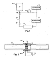
- Fig. 1 is a schematic view of a generalized cooler or refrigeration system, with MEMS flow controllers, in accordance with the present invention
- Fig. 2 is a schematic diagram of a MEMS flow controller for use with the cooler of Fig. 1 ;
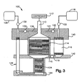
- Fig. 3 is a schematic diagram of a two-stage pulse tube cooler, with MEMS flow controllers, in accordance with the present invention.
- Fig. 4 is a schematic diagram of a multi-stage Stirling/pulse tube hybrid cooler, with a MEMS flow controller, in accordance with the present invention.
- a regenerative refrigeration system includes one or more control devices that utilize micro electro mechanical systems (MEMS) technology.
- MEMS devices may be small in size, on a scale such that it can be introduced into a refrigeration system, such as a cryocooler, without appreciably affecting the size or mass of the refrigeration system.
- a refrigeration system such as a cryocooler
- Suitable regenerative refrigeration systems for use with the MEMS devices include pulse tube coolers, Stirling coolers, and Gifford-McMahon coolers.
- Fig. 1 illustrates a generalized regenerative refrigerator or cooler system 10.
- the cooling system 10 includes a compressor 12, a regenerator 14, a pulse tube 16, and a surge volume 18.
- the compressor 12 is referred to herein as at the upstream end of the system, and the surge volume 18 is referred to as at the downstream end of the system 10.
- the downstream end of the compressor 12 is connected to the upstream end of the regenerator 14, the downstream end of the regenerator is connected to the upstream end of the pulse tube 16, and so forth.
- the system 10 includes a pair of MEMS flow controllers or devices 20 and 22, for controlling flow within the system 10.
- One of the MEMS devices 20 is between the pulse tube 16 and the surge volume 18.
- the other MEMS flow controller 22 is in a bypass line 26 that allows flow from the outlet (downstream end) of the compressor 12 to bypass the regenerator 14 and the pulse tube 16.
- the cooler 10 may have additional components such as an inertance tube 27 or an orifice 28 coupled to the pulse tube 16.
- the inertance tube 27 or the orifice 28 may aid in providing proper phase in the pulse tube 16.
- MEMS device and “MEMS flow controller,” as used herein, refer to micro-miniature flow controllers that are fabricated using micro electro mechanical systems (MEMS) technology.
- MEMS technology is a term used to describe manufacturing processes employed to produce devices with characteristic dimensions of nominally 1 to 10 microns.
- the most common MEMS fabrication technique is to utilize deep reactive ion etch (DRIE) processing to produce the desired structure in or from a silicon substrate.
- DRIE deep reactive ion etch
- Metal deposition techniques sputtering or vapor deposition
- Such metallization may be required, for instance, to carry current or serve as electrodes, or act as intermediate layers to improve the adhesion of subsequent layers.
- MEMS devices may be limited to those that can be applied at the micron scale.
- Typical actuation techniques include electrostatic, piezoelectric, electromagnetic, and thermal. Any suitable actuation technique may be utilized which is able to provide suitable flow rate, dynamic response, power efficiency, and/or other operating characteristics for MEMS devices or flow controllers.
- the requirements for such MEMS devices may vary widely depending on their location and use, so it is anticipated that different requirements will be met with different actuation techniques, as well as with different physical designs.
- MEMS devices may be configured to operate within small periods of time, such that their dynamic response is much faster than the operating speed of the cooling system.
- MEMS devices acting as the primary phase shifter 20 may have a response rate an order of magnitude faster than the frequency of the compressor 12, which may be a typical operating frequency such as 30 Hz or 60 Hz.
- the MEMS devices utilized herein may be considered as orifice or valve systems. Each such system contains one or more flow passages with active control. Active control may enable adjustment from closed to fully open, or over some smaller range. Each flow passage of a MEMS flow controller may have a characteristic dimension on the order of 1 mm. This invention improves in a number of aspects upon previous attempts to achieve active control (using macro systems): 1) overall size of the controller is not adversely impacted by introducing MEMS flow controllers; 2) MEMS flow controllers have minimal void volume; and 3) the small physical structures of MEMS flow controllers enable rapid dynamic response.
- the MEMS devices disclosed herein allow active flow control of flow within the pulse tube 16.
- the active control allows remote adjustments to be made in the operation of the system 10. For example, changes in operation may be made by sending communication signals over long distances (without direct physical contact with the system 10), for example to an orbiting spacecraft, to change the amount of current or otherwise actuate changes in a MEMS controller.
- the cooling/refrigeration system 10 shown in Fig. 1 is intended to be representative of a wide variety of regenerative refrigeration systems for which MEMS flow controllers or devices may be utilized.
- the regenerative refrigeration system 10 may be a system that operates on a modified Stirling thermodynamic cycle (a Stirling pulse tube).
- the regenerative refrigeration system may be a system that operates on a modified Ericson thermodynamic cycle, what is often referred to as a Gifford-McMahon pulse tube system. It will be appreciated that some such systems may not utilize all of the components shown in the example system of Fig. 1 .
- some systems may omit the surge volume 18, and/or may not utilize the bypass line 26.
- the cooling system 10 may have multiple bypass lines between various locations of the regenerator 14 and respective locations of the pulse tube 16.
- the locations of the MEMS flow controllers 20 and 22 in the system 10 are merely examples of possible locations of MEMS flow controllers.
- the system 10 may alternatively utilize only a single flow controller, such as the MEMS flow controller 20 between the pulse tube 16 and the surge volume 18.
- the system 10 may employ additional MEMS flow controllers, at different locations.
- Fig. 2 illustrates an example of details of the MEMS flow controller 20, which may be representative of a typical MEMS flow controller.
- the MEMS flow controller 20 is located in a flow passage 30 and controls flow within the flow passage 30.
- the MEMS device 20 has a plurality of flow passages 32 within a piezoelectric material 34.
- the piezoelectric material may be a suitable material with an asymmetric crystalline structure. Deformation of the piezoelectric material may be controlled by applying current from an AC current source 36.
- the current source 36 is coupled to the piezoelectric material through a hermetic electrical feedthrough 40.
- the piezoelectric material 34 may be deformed, changing the size and/or the shape of the flow passages 32.
- the flow passages 32 may be controlled as a group or individually, depending upon how the drive circuit is configured.
- the current source 36 may be one of multiple such current sources, for example, controlling deformation of different parts of the piezoelectric material 34. Thus a wide range of control of flow through the MEMS flow controller 20 may be rapidly accomplished, simply by controlling the input current.
- a MEMS device or flow controller such as the MEMS device 20 within the regenerative refrigeration system 10 allows many advantages in controlling operation of the cooler refrigeration system 10. Since only electrical signals may be needed as an input to reconfigure the MEMS device 20, remote control of the device may be possible. Remote control is defined herein as control that does not involve physical contact with the system 10 (such as through knobs, levers, wires, switches, etc.) to change operation of the system 10. Remote control of the flow characteristics of a flow restrictor, such as the MEMS device 20, results in more flexibility in achieving characteristics of the MEMS flow controller, and in more efficient evaluation of flow restrictor designs.
- MEMS flow controller 20 is electronically actuated, changes to flow characteristics can be accomplished without need for mechanical disassembly/re-assembly of the system 10.
- Engineering characterization testing that would typically require one or two days for each operational data point may be accomplished within one or two hours, through use of the MEMS flow controller 20.
- Full characterization testing that might require weeks or months of test time in prior systems may be accomplished within days in a refrigeration system utilizing MEMS flow controllers.
- MEMS flow controllers utilize minimal parasitic void volume. Excess void volume decreases system efficiency by forcing pressure cycling of additional volume that does not contribute to creating refrigeration.
- Flow characteristics of the MEMS flow controller 20/22 may be controllable during an individual cycle of the system, which is typically run at 30-60 Hz.
- the configuration of the one or more MEMS devices 20 and 22 may be tailored for optimum performance, and matched to operating conditions throughout each individual cycle.
- the flow characteristics may be optimized as a function of operating temperature (ambient to cryogenic during the cool-down transition) or applied heat lift (variable thermal loading at steady-state cryogenic temperature). Dynamic response of the MEMS flow controllers 20 and 22 allows the flexibility of real time tailoring of flow into and out of the pulse tube 16.
- the result may be a control of pressure wave forms and phase relationships that impact overall effectiveness of the pulse tube 16.
- reduction may be achieved in undesirable imbalance forces associated with pressure fluctuations.
- This enhanced controllability of the pulse tube 16 within the refrigeration system 10 offers a dimension of pulse tube cryocooler control that is not available in prior systems.
- Fig. 3 illustrates a two-stage pulse tube cooler 100 that utilizes MEMS devices.
- the cooling system 100 includes a compressor 112 that is coupled via a transfer line 113 to a first stage regenerator 114.
- a first stage flow shunt 115 couples outflow from the first stage regenerator 114 to the inlet of a first stage pulse tube 116.
- the first stage pulse tube 116 is coupled at its downstream end to a first surge volume 118.
- a shunt MEMS device 119 may be located in the first stage flow shunt 115 at an upstream end of the first stage regenerator 114.
- Another possibility is a MEMS device 120 located in a bypass line 121 at a downstream end of the fist stage regenerator 114.
- a first stage MEMS device 122 may be located between the first stage pulse tube 116 and the surge volume 118.
- the outlet (downstream end) of the first stage regenerator 114 is coupled to a second stage regenerator 124, which is in turn coupled to a second stage pulse tube 126.
- the second stage pulse tube 126 is coupled to a second surge volume 128.
- a second stage MEMS flow controller 130 may be located in the line between the second stage pulse tube 126 and the surge volume 128.
- a bypass MEMS flow controller 132 may be located in a bypass line 136 between the transfer 113 and the surge volume 128.
- the cooling system 100 provides two stages of cooling.
- An ambient temperature region 140 is upstream of the first stage regenerator 114, and downstream of the pulse tubes 116 and 126.
- a first cold stage 142 is located downstream of the first stage regenerator 114, and at the upstream side of the first stage pulse tube 116.
- a second cold stage 144 is located at the downstream end of the second stage regenerator 124, and the upstream end of the second stage pulse tube 126.
- the MEMS flow controllers 120, 122, 130 and/or 132 may be used to dynamically control operation of the cooling system 100. It will be appreciated that not all of the MEMS flow controllers shown in Fig. 3 need be used in the system. In fact, it is possible that a system may utilize only a single MEMS flow controller. In addition, it will be appreciated that different of the flow controllers 120, 122, 130, and 132, may have different functions. The flow controllers 122 and 130 may be utilized as the primary way of shifting phase within the respective pulse tubes 116 and 126.
- the flow controllers 122 and 130 allow control of the motion of the gas in the pulse tubes 116 and 126, which controls the phase angle between movement of the gas or the mass flow rate, and the expansion that occurs in both the first and second stages (at the locations 142 and 144), to create refrigeration.
- the shunt MEMS flow controller 120 may be used to bias the flow one way or another, either to the first stage pulse tube 116 or to the second stage pulse tube 126, for instance, to meet different operating points or even to meet duty cycle loads.
- the MEMS flow controller 120 may be used to control the relative cooling at the first stage portion 142 and the second stage portion 144.
- the bypass MEMS flow controller 132 controls movement of gas through the bypass line 136.
- Such bypass lines have been shown to improve performance of the second stage by controlling motion of the gas column without forcing all the gas to go all the way through the regenerators 114 and 124. Losses generated by passing the gas through the regenerators 114 and 124 may thus be reduced.
- Previous attempts using traditional, fixed bypass geometries have been shown to give rise to a net mass flow rate across the bypass when one considers the integrated, cyclical mass flow rate. This usually manifests as a flow from the compressor end to the surge volume in a single-stage pulse tube refrigerator, but such a "DC flow" in either direction is deleterious to performance.
- bypass MEMS flow controller 132 By controlling flow through the bypass line 136, through action of the bypass MEMS flow controller 132, undesired movement of gas from the bypass tube 136 to the downstream end of the second stage pulse tube 126, may be avoided. Such backflows from the bypass tube 136 to the second stage pulse tube 126 (and back through the regenerators 114 and 124 as well) involve losses due to the movement of hot gasses to the cold stages 142 and 144. These losses may be reduced or avoided by suitably setting the bypass MEMS flow controller 132.
- Fig. 4 shows a Stirling / pulse tube hybrid cooler 100', with MEMS flow controllers.
- the hybrid cooler 100' includes a compressor 112, and a Stirling expander 150 between the first stage regenerator 114 and the second stage regenerator 124.
- the second stage regenerator 124 is coupled to the second stage pulse tube 126.
- a second stage MEMS controller 130 Between the second stage pulse tube 126 and the surge volume 128 is a second stage MEMS controller 130, which may be configured to set (shift) the phase within the second stage pulse tube 126.
- the cooler 100' may have bypass lines 160 and 162 linking the surge volume 128 to the upstream ends of the regenerators 114 and 124, respectively.
- cryocoolers show in the Figures and discussed above are but a few examples of possible ways of employing MEMS devices or flow controllers within regenerative refrigeration systems.
- various functions may be had for the various MEMS flow controllers described herein, including set point control (controlling the set point of the system), and dynamic flow control.
- the MEMS flow controller operates as an ambient temperature, adjustable set point flow controller.
- One side of the MEMS flow controller/valve will be connected to a large pressure ballast (surge volume), making that side essentially isobaric. The other side will see an oscillating pressure wave.
- the use of the MEMS flow device in this example is as a primary phase shifter, or as a secondary "trim" phase shifter, for a pulse tube with a warm end ambient temperature.
- Basic requirements of the system are a warm end operating temperature of 250K to 320K; a pressure wave amplitude of 1.2 to 1.5 (P max /P min ); a nominal flow conductance of 0.01 to 0.05 (g/s)/atm; an adjustability of greater than ⁇ 25% of selected nominal flow conductance set point; a minimal void volume introduced on the side of the MEMS flow controller that sees the oscillating pressure wave ( ⁇ 0.2 cc, as an approximate); and a power of less than about 1 watt to set and maintain set point.
- the MEMS flow control device is an ambient temperature, adjustable set point flow controller, with controllable bias.
- One side of the MEMS flow controller will be connected to a large pressure ballast (surge volume), making it essentially isobaric. The other side will see an oscillating pressure wave.
- the bias of the MEMS flow controller (i.e., its flow in opposite directions) is also remotely controllable.
- the MEMS flow controller functions as a primary phase shifter or as a secondary "trim" phase shifter for a pressure tube with a warm end ambient temperature.
- the controllable bias provides an additional degree of control over the configuration in Example 1.
- the basic requirements for the system are a warm end operating temperature of 250K to 320K; a pressure wave amplitude of 1.2 to 1.5 (P max /P min ); a nominal flow conductance of 0.01 to 0.05 (g/s)/atm; an adjustability of greater than ⁇ 25% of selected nominal flow conductance set point; a bias of greater than ⁇ 10%; a minimal void volume introduced on the side of the MEMS flow controller that sees the oscillating pressure wave ( ⁇ 0.2 cc, as an approximate); and a power of less than about 1 watt to set and maintain set point and bias.
- the MEMS flow controller functions as an ambient temperature, dynamic flow controller, with adjustment to allow it to be synchronized with the operating frequency of the cooling system. As in Examples 1 and 2, one side of the flow controller will be essentially isobaric while the other will see an operating pressure wave.
- the MEMS device may be either a single device, or a simple combination of various valves/devices.
- the dynamic flow control provides an additional degree of control over that achieved in Examples 1 and 2.
- the basic requirements of the system are a warm end operating temperature of 250K to 320K; a pressure wave amplitude of 1.2 to 1.5 (P max /P min ); a nominal flow conductance of 0.01 to 0.05 (g/s)/atm; an adjustability of greater than ⁇ 25% of selected nominal flow conductance set point, with an adjustability of 100% desirable (this type of adjustability automatically provides bias capability); a minimal void volume introduced on the side of the MEMS flow controller that sees the oscillating pressure wave ( ⁇ 0.2 cc, as an approximate); a power of less than about 1 watt to set and maintain set point; and operating frequency >1kHz (0.999 dynamic response in 0.001 seconds).
- the MEMS flow device is used as a cryogenic temperature, adjustable set point flow controller, allowing remote adjustment. As with the examples above, one side of the flow controller is essentially isobaric and the other side sees an oscillating pressure wave. There may be a requirement for the device to be compact, because it is located in a cryogenic region.
- the use of the MEMS flow device may be as a primary phase shifter or secondary "trim” phase shifter for a pulse tube with its "warm end" at cryogenic temperature, as might be found in the colder stage or stages of a multistage pulse tube or hybrid Stirling/pulse tube cooler.
- the basic requirements of the system are an operating temperature of 20K to 150K; a pressure wave amplitude of 1.2 to 1.5 (P max /P min ); a nominal flow conductance of 0.01 to 0.05 (g/s)/atm; an adjustability of greater than ⁇ 25% of selected nominal flow conductance set point; a minimal void volume introduced on the side of the MEMS flow controller that sees the oscillating pressure wave ( ⁇ 0.2 cc, as an approximate); and a power of less than about 0.3 watt to set and maintain set point.
- the MEMS flow device is used as a cryogenic temperature, adjustable set point flow controller with controllable bias, allowing for remote adjustment.
- the conditions for this example are the same as for Example 2, with the exceptions that the operating temperature is 20K to 150K, and the power is less than about 0.3 watts to set and maintain set point and bias.
- the MEMS flow device is a cryogenic temperature, dynamic flow controller that allows remote adjustment, and is synchronized with the operating frequency of the system.
- the conditions for this example are the same as for Example 3 (described above), with the exception that the operating temperature is 20K to 150K, and the power is less than about 0.3W to set and maintain the set point.
- the MEMS flow device is used as ambient bypass flow controller, to allow direct porting of working gas from one portion of the cooler to another, such as is required for the "double-inlet" pulse tube configuration.
- both sides of the MEMS flow controller see an oscillating pressure wave, albeit of different amplitude and phase.
- the functionality of the MEMS flow device may be achieved by either a single flow controller, or by a simple combination of flow controllers. Controllability of the flow bias may be important for this application.
- the use of the MEMS flow device is to allow flow bypass from an expander inlet to a pulse tube warm end, to decrease regenerator loss, and in doing so to increase refrigeration capacity.
- Basic requirements of the system are a warm end operating temperature of 250K to 320K; a pressure wave amplitude of 1.2 to 1.5 (P max /P min ); a nominal flow conductance of 0.005 to 0.01 (g/s)/atm; an adjustability of greater than ⁇ 25% of selected nominal flow conductance set point, with an adjustability of 100% desirable (this type of adjustability automatically provides bias capability); a bias of greater than ⁇ 10%; minimal void volume on both sides of the valve; and a power of less than about 1 watt to set and maintain set point and bias.
- the MEMS flow device is used as a cryogenic bypass flow controller.
- the basic requirements of the system are the same as in Example 7, with the exceptions that the warm end operating temperature is 20K to 150K, and the power is less than about 0.3 watts to set and maintain set point and bias.
- the MEMS flow controller is used as a dynamic bypass flow controller.
- the basic system requirements are the same as in Example 7, with the additional requirement that the dynamic response be greater than about 1 kHz.
- the MEMS flow controller is used as a dynamic, cryogenic bypass flow controller.
- the basic requirements are the same as in Example 7, with the warm end operating temperature being 20K to 150K, the power is less than about 0.3 watts to set and maintain set point and bias, and with the additional requirement that the dynamic response is greater than about 1 kHz.
- MEMS flow controllers to control flow inside a pulse tube refrigerator.
- Such MEMS devices may function as a reconfigurable orifice, with the amount of flow restriction being controlled by an input signal.
- Such a device may be set remotely, where physical contact with refrigerator is impractical of impossible.
- MEMS flow controllers may function within the refrigerator in any of the following ways: as a primary phase shifter; as a secondary phase shifter (for example, in addition to an orifice, an inertance tube, etc.); to control flow in a bypass line (for instance, in a "double-inlet” pulse tube); or as a flow splitter to regular flow allocation between stages in a multi-stage cooler or refrigerator.
Landscapes
- Engineering & Computer Science (AREA)
- Physics & Mathematics (AREA)
- Mechanical Engineering (AREA)
- Thermal Sciences (AREA)
- General Engineering & Computer Science (AREA)
- Flow Control (AREA)
- Details Of Measuring And Other Instruments (AREA)
Claims (8)
- Regeneratives Kühlgerät (10, 100, 100'), das umfasst:einen Kompressor (12, 112);einen Regenerator (14, 114), der mit einem Auslassende des Kompressors gekoppelt ist;ein Impulsrohr (16, 116), das mit einem Auslassende des Regenerators gekoppelt ist;ein Ausgleichsvolumen (18, 118), das mit einem Auslassende des Impulsrohrs gekoppelt ist; undeine Durchflusssteuereinheit (20, 22, 120, 122, 130, 132), um den Durchfluss in dem Kühlgerät zu steuern, dadurch gekennzeichnet, dass:die Durchflusssteuereinheit eine Durchflusssteuereinheit für mikro-elektromechanische Systeme (MEMS-Durchflusssteuereinheit) ist; wobeidie MEMS-Durchflusssteuereinheit eine einstellbare Durchflussdrossel ist, die konfiguriert ist, um den Durchfluss dynamisch mit einer Rate einzustellen, die wenigstens so schnell ist wie eine Zyklusrate des Kompressors; unddie Durchflussdrossel eine vorbelastete Durchflussdrossel ist, die vorbelastet ist und eine größere Durchflussbeschränkung in einer Richtung als ein einer entgegengesetzten Richtung besitzt.
- Kühlgerät nach Anspruch 1,
wobei die MEMS-Durchflusssteuereinheit als ein Phasenschieber arbeitet, um die Phase in dem Impulsrohr zu steuern; und
wobei die MEMS-Durchflusssteuereinheit zwischen dem Impulsrohr und dem Ausgleichsvolumen vorgesehen ist. - Kühlgerät nach Anspruch 1, das ferner umfasst:ein Ausgleichsvolumen (18, 118), das mit einem Auslassende des Impulsrohrs gekoppelt ist; undeine Nebenleitung (26, 121), die das Einlassende des Regenerators mit dem Auslassende des Impulsrohrs koppelt;wobei die MEMS-Durchflusssteuereinheit in der Nebenleitung vorhanden ist.
- Kühlgerät nach Anspruch 1,
wobei das Kühlgerät ein mehrstufiges Kühlgerät ist, wobei der Regenerator ein Regenerator (114) erster Stufe ist und das Impulsrohr ein Impulsrohr (116) erster Stufe ist; und ferner mit:einem ersten Ausgleichsvolumen (118), das mit einer Auslassseite des Impulsrohrs erster Stufe gekoppelt ist;einem Regenerator (124) zweiter Stufe, der mit dem Auslassende des Regenerators erster Stufe gekoppelt ist;einem Impulsrohr (126) zweiter Stufe, das mit einem Auslassende des Regenerators zweiter Stufe gekoppelt ist; undeinem zweiten Ausgleichsvolumen (128), das mit einem Auslassende des Impulsrohrs zweiter Stufe gekoppelt ist. - Kühlgerät nach Anspruch 4, wobei die MEMS-Durchflusssteuereinheit zwischen einem der Impulsrohre und dem mit diesem Impulsrohr gekoppelten Ausgleichsvolumen vorhanden ist.
- Kühlgerät nach Anspruch 4, wobei die MEMS-Durchflusssteuereinheit zwischen dem Auslassende des Regenerators erster Stufe und einem Einlassende des Impulsrohrs erster Stufe vorhanden ist, um dadurch die Zuweisung zwischen Stufen des Regenerators zu steuern.
- Kühlgerät nach einem der Ansprüche 1 bis 6,
wobei die MEMS-Durchflusssteuereinheit eine dynamische Durchflusssteuerung für das Kühlgerät schafft und den Durchfluss in einem einzigen Zyklus des Kompressors einstellt; und
wobei die MEMS-Durchflusssteuereinheit eine Ansprechzeit von weniger als etwa 1/60 einer Sekunde hat. - Verfahren zum Betreiben des regenerativen Kühlschranks nach einem der Ansprüche 1 bis 7, wobei das Verfahren umfasst:zyklisches Betreiben des Kompressors des Kühlgeräts, um einen zyklischen Durchfluss durch den Regenerator und das Impulsrohr zu veranlassen; undEinstellen der MEMS-Durchflusssteuereinheit des Kühlgeräts, um den Massendurchfluss an wenigstens einer Stelle in dem Kühlgerät einzustellen,wobei das Einstellen das dynamische Einstellen der wenigstens eine MEMS-Durchflusssteuereinheit mit einer Rate, die wenigstens so schnell ist wie eine Zyklusrate des Kompressors, umfasst.
Applications Claiming Priority (1)
| Application Number | Priority Date | Filing Date | Title |
|---|---|---|---|
| US10/974,154 US7263838B2 (en) | 2004-10-27 | 2004-10-27 | Pulse tube cooler with internal MEMS flow controller |
Publications (3)
| Publication Number | Publication Date |
|---|---|
| EP1653167A2 EP1653167A2 (de) | 2006-05-03 |
| EP1653167A3 EP1653167A3 (de) | 2007-12-19 |
| EP1653167B1 true EP1653167B1 (de) | 2011-11-09 |
Family
ID=35787958
Family Applications (1)
| Application Number | Title | Priority Date | Filing Date |
|---|---|---|---|
| EP05255570A Ceased EP1653167B1 (de) | 2004-10-27 | 2005-09-12 | Schwingrohrkältemaschine mit einem inneren mikroelektromechanischen Volumenstromregler |
Country Status (2)
| Country | Link |
|---|---|
| US (1) | US7263838B2 (de) |
| EP (1) | EP1653167B1 (de) |
Families Citing this family (9)
| Publication number | Priority date | Publication date | Assignee | Title |
|---|---|---|---|---|
| US20070261416A1 (en) * | 2006-05-11 | 2007-11-15 | Raytheon Company | Hybrid cryocooler with multiple passive stages |
| US7614240B2 (en) * | 2006-09-22 | 2009-11-10 | Praxair Technology, Inc. | Control method for pulse tube cryocooler |
| WO2008125139A1 (en) * | 2007-04-17 | 2008-10-23 | Cern-European Organisation For Nuclear Research | Pulse tube cryocooler with compact size and decreased dead volume |
| US20090084114A1 (en) * | 2007-09-28 | 2009-04-02 | Yuan Sidney W K | Gas phase shifting inertance gap pulse tube cryocooler |
| US20090084116A1 (en) * | 2007-09-28 | 2009-04-02 | Yuan Sidney W K | Gas phase shifting multistage displacer cryocooler |
| US20090084115A1 (en) * | 2007-09-28 | 2009-04-02 | Yuan Sidney W K | Controlled and variable gas phase shifting cryocooler |
| JP5606748B2 (ja) * | 2010-02-03 | 2014-10-15 | 住友重機械工業株式会社 | パルスチューブ冷凍機 |
| US9570220B2 (en) * | 2012-10-08 | 2017-02-14 | General Electric Company | Remote actuated cryocooler for superconducting generator and method of assembling the same |
| WO2023211563A1 (en) * | 2022-04-25 | 2023-11-02 | The Regents Of The University Of Colorado, A Body Corporate | Dynamic acoustic impedance matching for cryocoolers |
Family Cites Families (17)
| Publication number | Priority date | Publication date | Assignee | Title |
|---|---|---|---|---|
| US4538642A (en) * | 1984-04-20 | 1985-09-03 | Eaton Corporation | Fast acting valve |
| DE3917423C1 (de) * | 1989-05-29 | 1990-05-31 | Buerkert Gmbh & Co Werk Ingelfingen, 7118 Ingelfingen, De | |
| US5335505A (en) * | 1992-05-25 | 1994-08-09 | Kabushiki Kaisha Toshiba | Pulse tube refrigerator |
| JP3625511B2 (ja) * | 1995-02-23 | 2005-03-02 | 株式会社鈴木商館 | ガスサイクル冷凍機 |
| JP3624542B2 (ja) * | 1996-04-30 | 2005-03-02 | アイシン精機株式会社 | パルス管冷凍機 |
| US6167707B1 (en) | 1999-04-16 | 2001-01-02 | Raytheon Company | Single-fluid stirling/pulse tube hybrid expander |
| US6330800B1 (en) | 1999-04-16 | 2001-12-18 | Raytheon Company | Apparatus and method for achieving temperature stability in a two-stage cryocooler |
| US7106493B2 (en) * | 1999-07-27 | 2006-09-12 | Sanford James E | MEMS-based valve device |
| US6385972B1 (en) * | 1999-08-30 | 2002-05-14 | Oscar Lee Fellows | Thermoacoustic resonator |
| US6256998B1 (en) * | 2000-04-24 | 2001-07-10 | Igcapd Cryogenics, Inc. | Hybrid-two-stage pulse tube refrigerator |
| US6378312B1 (en) * | 2000-05-25 | 2002-04-30 | Cryomech Inc. | Pulse-tube cryorefrigeration apparatus using an integrated buffer volume |
| WO2002033268A2 (en) * | 2000-10-18 | 2002-04-25 | Research Foundation Of State University Of New York | Microvalve |
| US6595006B2 (en) * | 2001-02-13 | 2003-07-22 | Technology Applications, Inc. | Miniature reciprocating heat pumps and engines |
| US6754510B2 (en) * | 2001-12-13 | 2004-06-22 | Superconductor Technologies, Inc. | MEMS-based bypass system for use with a HTS RF receiver |
| US6629418B1 (en) * | 2002-01-08 | 2003-10-07 | Shi-Apd Cryogenics, Inc. | Two-stage inter-phasing pulse tube refrigerators with and without shared buffer volumes |
| US6910332B2 (en) * | 2002-10-15 | 2005-06-28 | Oscar Lee Fellows | Thermoacoustic engine-generator |
| US7017351B2 (en) * | 2002-11-21 | 2006-03-28 | Mems Optical, Inc. | Miniature thermoacoustic cooler |
-
2004
- 2004-10-27 US US10/974,154 patent/US7263838B2/en not_active Expired - Lifetime
-
2005
- 2005-09-12 EP EP05255570A patent/EP1653167B1/de not_active Ceased
Also Published As
| Publication number | Publication date |
|---|---|
| US7263838B2 (en) | 2007-09-04 |
| US20060086098A1 (en) | 2006-04-27 |
| EP1653167A2 (de) | 2006-05-03 |
| EP1653167A3 (de) | 2007-12-19 |
Similar Documents
| Publication | Publication Date | Title |
|---|---|---|
| US6256998B1 (en) | Hybrid-two-stage pulse tube refrigerator | |
| EP1653167B1 (de) | Schwingrohrkältemaschine mit einem inneren mikroelektromechanischen Volumenstromregler | |
| US20030101732A9 (en) | Miniature reciprocating heat pumps and engines | |
| EP3642542B1 (de) | Mems-kryokühlersysteme und -verfahren | |
| US20110000228A1 (en) | Hybrid cryocooler with multiple passive stages | |
| US5642623A (en) | Gas cycle refrigerator | |
| US5345769A (en) | Cryogenic refrigeration apparatus | |
| US20090084116A1 (en) | Gas phase shifting multistage displacer cryocooler | |
| US20090084115A1 (en) | Controlled and variable gas phase shifting cryocooler | |
| US5867991A (en) | Ferroelectric Stirling-cycle refrigerator | |
| US20090084114A1 (en) | Gas phase shifting inertance gap pulse tube cryocooler | |
| CN113074470B (zh) | 一种具有低温腔结构的脉管制冷机 | |
| Burger et al. | 165 K microcooler operating with a sorption compressor and a micromachined cold stage | |
| US7093449B2 (en) | Stirling/pulse tube hybrid cryocooler with gas flow shunt | |
| Burger | Cryogenic Microcooling, A micromachined cold stage operating with a sorption compressor in a vapor compression cycle | |
| Cai et al. | Experimental analysis of the multi-bypass principle in pulse tube refrigerators | |
| JP2004301445A (ja) | パルス管冷凍機 | |
| WO2006078437A1 (en) | Multi-stage cryocooler with concentric second stage | |
| Burger et al. | High pressure check valve for application in a miniature cryogenic sorption cooler | |
| Hannon et al. | Development of a Medium-Scale Collins-Type 10 K Cryocooler | |
| Radebaugh et al. | Proposed rapid cooldown technique for pulse tube cryocoolers | |
| Hannon et al. | Development of a Small-Scale Collins Type Cryogenic Refrigerator | |
| Wang et al. | High efficiency, single-stage GM cryorefrigerators optimized for 20 to 40K | |
| Nieczkoski et al. | Development of a Novel Brayton‐Cycle Cryocooler and Key Component Technologies | |
| Hannon et al. | Development of a Small-Scale Collins Type Cryocooler for Space and Terrestrial Applications |
Legal Events
| Date | Code | Title | Description |
|---|---|---|---|
| PUAI | Public reference made under article 153(3) epc to a published international application that has entered the european phase |
Free format text: ORIGINAL CODE: 0009012 |
|
| AK | Designated contracting states |
Kind code of ref document: A2 Designated state(s): AT BE BG CH CY CZ DE DK EE ES FI FR GB GR HU IE IS IT LI LT LU LV MC NL PL PT RO SE SI SK TR |
|
| AX | Request for extension of the european patent |
Extension state: AL BA HR MK YU |
|
| PUAL | Search report despatched |
Free format text: ORIGINAL CODE: 0009013 |
|
| AK | Designated contracting states |
Kind code of ref document: A3 Designated state(s): AT BE BG CH CY CZ DE DK EE ES FI FR GB GR HU IE IS IT LI LT LU LV MC NL PL PT RO SE SI SK TR |
|
| AX | Request for extension of the european patent |
Extension state: AL BA HR MK YU |
|
| 17P | Request for examination filed |
Effective date: 20080618 |
|
| AKX | Designation fees paid |
Designated state(s): DE FR GB |
|
| 17Q | First examination report despatched |
Effective date: 20081208 |
|
| GRAP | Despatch of communication of intention to grant a patent |
Free format text: ORIGINAL CODE: EPIDOSNIGR1 |
|
| GRAS | Grant fee paid |
Free format text: ORIGINAL CODE: EPIDOSNIGR3 |
|
| GRAA | (expected) grant |
Free format text: ORIGINAL CODE: 0009210 |
|
| AK | Designated contracting states |
Kind code of ref document: B1 Designated state(s): DE FR GB |
|
| REG | Reference to a national code |
Ref country code: GB Ref legal event code: FG4D |
|
| REG | Reference to a national code |
Ref country code: DE Ref legal event code: R096 Ref document number: 602005031082 Country of ref document: DE Effective date: 20120119 |
|
| PLBE | No opposition filed within time limit |
Free format text: ORIGINAL CODE: 0009261 |
|
| STAA | Information on the status of an ep patent application or granted ep patent |
Free format text: STATUS: NO OPPOSITION FILED WITHIN TIME LIMIT |
|
| 26N | No opposition filed |
Effective date: 20120810 |
|
| REG | Reference to a national code |
Ref country code: DE Ref legal event code: R097 Ref document number: 602005031082 Country of ref document: DE Effective date: 20120810 |
|
| REG | Reference to a national code |
Ref country code: FR Ref legal event code: PLFP Year of fee payment: 12 |
|
| REG | Reference to a national code |
Ref country code: FR Ref legal event code: PLFP Year of fee payment: 13 |
|
| REG | Reference to a national code |
Ref country code: FR Ref legal event code: PLFP Year of fee payment: 14 |
|
| PGFP | Annual fee paid to national office [announced via postgrant information from national office to epo] |
Ref country code: GB Payment date: 20200902 Year of fee payment: 16 Ref country code: FR Payment date: 20200812 Year of fee payment: 16 Ref country code: DE Payment date: 20200901 Year of fee payment: 16 |
|
| REG | Reference to a national code |
Ref country code: DE Ref legal event code: R119 Ref document number: 602005031082 Country of ref document: DE |
|
| GBPC | Gb: european patent ceased through non-payment of renewal fee |
Effective date: 20210912 |
|
| PG25 | Lapsed in a contracting state [announced via postgrant information from national office to epo] |
Ref country code: GB Free format text: LAPSE BECAUSE OF NON-PAYMENT OF DUE FEES Effective date: 20210912 Ref country code: FR Free format text: LAPSE BECAUSE OF NON-PAYMENT OF DUE FEES Effective date: 20210930 Ref country code: DE Free format text: LAPSE BECAUSE OF NON-PAYMENT OF DUE FEES Effective date: 20220401 |