EP1653060A1 - Spritzdüse zur Kühlung eines Kolbens einer Brennkraftmaschine - Google Patents
Spritzdüse zur Kühlung eines Kolbens einer Brennkraftmaschine Download PDFInfo
- Publication number
- EP1653060A1 EP1653060A1 EP05021250A EP05021250A EP1653060A1 EP 1653060 A1 EP1653060 A1 EP 1653060A1 EP 05021250 A EP05021250 A EP 05021250A EP 05021250 A EP05021250 A EP 05021250A EP 1653060 A1 EP1653060 A1 EP 1653060A1
- Authority
- EP
- European Patent Office
- Prior art keywords
- bore
- spray nozzle
- sleeve body
- crankcase
- nozzle
- Prior art date
- Legal status (The legal status is an assumption and is not a legal conclusion. Google has not performed a legal analysis and makes no representation as to the accuracy of the status listed.)
- Granted
Links
Images
Classifications
-
- F—MECHANICAL ENGINEERING; LIGHTING; HEATING; WEAPONS; BLASTING
- F01—MACHINES OR ENGINES IN GENERAL; ENGINE PLANTS IN GENERAL; STEAM ENGINES
- F01P—COOLING OF MACHINES OR ENGINES IN GENERAL; COOLING OF INTERNAL-COMBUSTION ENGINES
- F01P3/00—Liquid cooling
- F01P3/06—Arrangements for cooling pistons
- F01P3/08—Cooling of piston exterior only, e.g. by jets
-
- F—MECHANICAL ENGINEERING; LIGHTING; HEATING; WEAPONS; BLASTING
- F02—COMBUSTION ENGINES; HOT-GAS OR COMBUSTION-PRODUCT ENGINE PLANTS
- F02F—CYLINDERS, PISTONS OR CASINGS, FOR COMBUSTION ENGINES; ARRANGEMENTS OF SEALINGS IN COMBUSTION ENGINES
- F02F3/00—Pistons
- F02F3/16—Pistons having cooling means
- F02F3/20—Pistons having cooling means the means being a fluid flowing through or along piston
- F02F3/22—Pistons having cooling means the means being a fluid flowing through or along piston the fluid being liquid
Definitions
- the invention relates to a spray nozzle for cooling a piston of an internal combustion engine according to the features of the preamble of patent claim 1.
- So-called piston spray nozzles for cooling the high-temperature-loaded pistons are in particular used in high-performance engines.
- the inclusion or attachment of these spray nozzles in the engine or crankcase of the engine takes place in various ways.
- the spray nozzle is screwed into the crankcase;
- the spray nozzle on a fastening tab which is fixed with a screw on the crankcase. Since the spray nozzle are mounted in the region of the bearing blocks of the crankcase, such attachment leads to an unwanted weakening of the bearing block.
- the object of the invention is to attach the spray nozzle to the crankcase so that a simple installation and tension-free recording of the spray nozzle in the bore is possible, and a weakening of the crankcase in the bearing block area is prevented.
- the fuse element provided on the spray nozzle which engages with a section in a bore provided in the crankcase, ensures in a simple manner that the spray nozzle can no longer rotate after being received in the bore provided in the crankcase.
- An interference fit between the sleeve of the spray nozzle and the bore is thus no longer necessary; a transition fit is sufficient to seal the sleeve of the spray nozzle relative to the bore wall.
- a disk or oval sheet formed securing element is disposed between the sleeve body and the actual nozzle and thus serves at the same time as an axial stop surface for the inserted into the bore sleeve body of the spray nozzle.
- annular groove is provided at the end of the sleeve body received in the bore, in which a spring ring is received for locking the sleeve body in the bore;
- the bore In the area of the spring ring, the bore has a step, so that the shoulder that forms thereby acts as a stop for the spring ring.
- the supply of spray oil takes place in an advantageous manner via the oil supply groove provided for the main bearings of the crankshaft.
- the sleeve body receiving bore communicates with the main bearing ⁇ lumpssnut.
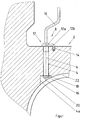
- the single FIGURE shows a nozzle attached to the crankcase of an internal combustion engine for cooling a piston.
- crankcase 2 of an internal combustion engine is partially shown in the bearing block area of the crankshaft.
- a sleeve body 6 of a spray nozzle 8 is received for cooling a piston of an internal combustion engine.
- the spray nozzle 8 has a hook-shaped nozzle line 10, via the free end of which the piston head is acted upon by spray oil for cooling.
- a securing element 12 is provided, whose base body 12a is disc-shaped or oval-shaped and has an extension 12b, which engages in a provided in the crankcase 2 blind hole 14.
- the extension 12b is, for example, as angled locking nose, locking pin, security pin o.ä. educated.
- a design is also conceivable in which the securing part engaging in the bore 14 is punched out of the locking plate itself as a securing section. This ensures that the spray nozzle can no longer rotate after its installation.
- the recorded in the bore 4 end of the sleeve body 6 has an annular groove 16 in which a spring ring 18 is receiving.
- the spring ring 18 is used for axial securing of the spray nozzle 8 in the crankcase 2.
- the step 20 serves as a stop surface for the spring ring 18 and thus ensures that the spray nozzle 8 is locked captive in the bore 4.
- the outer diameter of the sleeve body 6 and the diameter of the bore 4 are formed, for example, as a transition fit, so that a sufficient seal is ensured. Additionally or alternatively to the transition fit, it is also conceivable that a sealing of the sleeve body 6 in the bore 4 by a 0-ring, which is selectively inserted either in the bore 4 or in an annular groove in the sleeve body 6. The position of this 0-ring would be at the beginning of the bore 4, directly in the area under the fuse element 12, provide.
Landscapes
- Engineering & Computer Science (AREA)
- Chemical & Material Sciences (AREA)
- Combustion & Propulsion (AREA)
- Mechanical Engineering (AREA)
- General Engineering & Computer Science (AREA)
- Physics & Mathematics (AREA)
- Fluid Mechanics (AREA)
- Pistons, Piston Rings, And Cylinders (AREA)
- Lubrication Of Internal Combustion Engines (AREA)
Abstract
Description
- Die Erfindung betrifft eine Spritzdüse zur Kühlung eines Kolbens einer Brennkraftmaschine gemäß den Merkmalen des Oberbegriffs des Patentanspruchs 1.
- So genannte Kolbenspritzdüsen zur Kühlung der hochtemperaturbelasteten Kolben sind insbesondere bei leistungsstarken Motoren im Einsatz. Die Aufnahme bzw. Befestigung dieser Spritzdüsen im Motor- bzw. Kurbelgehäuse der Brennkraftmaschine erfolgt auf verschiedene Art und Weise. Es gibt Ausführungen, bei denen die Spritzdüse im Kurbelgehäuse verschraubt ist; dazu weist die Spritzdüse eine Befestigungslasche auf, die mit einer Schraube am Kurbelgehäuse fixiert ist. Da die Spritzdüse im Bereich der Lagerstühle des Kurbelgehäuses angebracht sind, führt eine derartige Befestigung zu einer ungewünschten Schwächung des Lagerstuhls.
- Aus der EP 0 785 344 B1 ist eine Kolbenspritzdüse sowie deren Befestigung im Motorgehäuse dargestellt und beschrieben, wobei eine Muffe bzw. der zylindrische Grundkörper der Kolbenspritzdüse in einer im Motorgehäuse vorgesehenen Bohrung als Presspassung aufgenommen ist. Zur lagerichtigen Positionierung besitzt die Düse zwei gegenüberliegende Referenzseitenflächen, die zum Biegen und zur Positionierung der Düse im Motor vorgesehen sind. Nachteilig bei dieser Ausführung ist es, dass durch die vorgesehene Presspassung unerwünschte Spannungen aufgebaut werden; darüber hinaus muss die Spritzdüse im eingebauten Zustand noch einjustiert werden.
- Aufgabe der Erfindung ist es, die Spritzdüse so am Kurbelgehäuse zu befestigen, dass eine einfache Montage und spannungsfreie Aufnahme der Spritzdüse in der Bohrung möglich ist, sowie eine Schwächung des Kurbelgehäuses im Lagerstuhlbereich verhindert wird.
- Die Aufgabe wird durch die im Anspruch 1 angegebenen Merkmale gelöst.
- Das an der Spritzdüse vorgesehene Sicherungselement, das mit einem Abschnitt in eine im Kurbelgehäuse vorgesehene Bohrung eingreift, stellt auf einfache Art und Weise sicher, dass sich die Spritzdüse nach der Aufnahme in der im Kurbelgehäuse vorgesehenen Bohrung nicht mehr verdrehen kann. Eine Presspassung zwischen der Hülse der Spritzdüse und der Bohrung ist damit nicht mehr erforderlich; eine Übergangspassung genügt, um die Hülse der Spritzdüse gegenüber der Bohrungswandung abzudichten.
- Weitere vorteilhafte Ausgestaltungen und Weiterbildungen der Spritzdüse sind in den Unteransprüchen angegeben.
- Das bspw. als Scheibe oder ovales Blech ausgebildete Sicherungselement ist zwischen Hülsenkörper und der eigentlichen Düse angeordnet und dient damit gleichzeitig als axiale Anschlagfläche für den in die Bohrung eingesteckten Hülsenkörper der Spritzdüse.
- Zur weiteren axialen Arretierung der Spritzdüse ist an dem in der Bohrung aufgenommenen Ende des Hülsenkörpers eine Ringnut vorgesehen, in der zur Arretierung des Hülsenkörpers in der Bohrung ein Federring Aufnahme findet; im Bereich des Federringes weist die Bohrung eine Stufe auf, so dass der sich dabei ausbildende Absatz als Anschlag für den Federring wirkt. Damit ist der Hülsenkörper der Spritzdüse verliersicher in der Bohrung gehalten.
- Die Versorgung mit Spritzöl erfolgt auf vorteilhafte Art und Weise über die für die Hauptlager der Kurbelwelle vorgesehene Ölversorgungsnut. Dazu steht die den Hülsenkörper aufnehmende Bohrung mit der Hauptlager-Ölversorgungsnut in Verbindung.
- Die Erfindung wird nachfolgend anhand der Beschreibung und der Zeichnung näher erläutert.
- Die einzige Figur zeigt eine im Kurbelgehäuse einer Brennkraftmaschine befestigte Spritzdüse zur Kühlung eines Kolbens.
- In der Figur ist teilweise das Kurbelgehäuse 2 einer Brennkraftmaschine im Lagerstuhlbereich der Kurbelwelle dargestellt. In einer zum Hauptlager der Kurbelwelle führenden Bohrung 4 ist ein Hülsenkörper 6 einer Spritzdüse 8 zur Kühlung eines Kolbens einer Brennkraftmaschine aufgenommen. Zur Beaufschlagung des Kolbenbodens des sich in einem nicht dargestellten Zylinder auf und ab bewegenden Kolbens weist die Spritzdüse 8 eine hakenförmig ausgebildete Düsenleitung 10 auf, über deren freies Ende der Kolbenboden zur Kühlung mit Spritzöl beaufschlagt wird.
- Zur Lagepositionierung der Spritzdüse 8 bzw. als Verdrehsicherung ist zwischen Hülsenkörper 6 und Düsenleitung 10 ein Sicherungselement 12 vorgesehen, dessen Grundkörper 12a scheiben- bzw. ovalförmig ausgebildet ist und einen Fortsatz 12b aufweist, der in eine im Kurbelgehäuse 2 vorgesehene Sacklochbohrung 14 eingreift. Der Fortsatz 12b ist bspw. als abgewinkelte Sicherungsnase, Sicherungsstift, Sicherungspin o.ä. ausgebildet. Alternativ zum Fortsatz 12b ist auch eine Ausführung denkbar, bei der das in die Bohrung 14 eingreifende Sicherungsteil als Sicherungsabschnitt aus dem Sicherungsblech selbst herausgestanzt ist. Damit ist sichergestellt, dass sich die Spritzdüse nach ihrer Montage nicht mehr verdrehen kann.
- Das in der Bohrung 4 aufgenommene Ende des Hülsenkörpers 6 weist eine Ringnut 16 auf, in der ein Federring 18 Aufnahme findet. Der Federring 18 dient zur axialen Sicherung der Spritzdüse 8 im Kurbelgehäuse 2. Dazu weist die Bohrung 4 im Bereich des Federrings 18 eine Stufe bzw. Absatz 20 auf, die in einen Bohrungsabschnitt 4a mit einem größeren Bohrungsdurchmesser übergeht. Die Stufe 20 dient dabei als Anschlagfläche für den Federring 18 und stellt damit sicher, dass die Spritzdüse 8 in der Bohrung 4 verliersicher arretiert ist. Bei der Montage der Spritzdüse 8 wird der Hülsenkörper 6 in die Bohrung 4 eingeführt, wobei der Federring 18 beim Erreichen des Bohrungsabschnittes 4a sich aufweitet und somit die Spritzdüse 8 axial fixiert. Über die in der Figur nur teilweise dargestellte Ölversorgungsnut 22 für die Hauptlager der Kurbelwelle wird das zur Kühlung dienende Schmieröl über die im Hülsenkörper 6 und in der Düsenleitung 10 ausgebildeten Kanäle dem Kolben zugeführt.
- Der Außendurchmesser des Hülsenkörpers 6 und der Durchmesser der Bohrung 4 sind beispielsweise als Übergangspassung ausgebildet, so dass eine ausreichende Abdichtung sichergestellt ist. Zusätzlich oder alternativ zur Übergangspassung ist es auch denkbar, dass eine Abdichtung des Hülsenkörpers 6 in der Bohrung 4 durch einen 0-Ring erfolgt, der wahlweise entweder in der Bohrung 4 oder in einer Ringnut im Hülsenkörper 6 eingelegt ist. Die Lage dieses 0-Ringes wäre dabei am Anfang der Bohrung 4, unmittelbar im Bereich unter dem Sicherungselement 12, vorzusehen.
Claims (4)
- Spritzdüse zur Kühlung eines Kolbens einer Brennkraftmaschine, mit einem Hülsenkörper (6) der in einer Bohrung (4) im Kurbelgehäuse (2) der Brennkraftmaschine Aufnahme findet und in dem ein Ölzufuhrkanal ausgebildet ist, einer mit dem Hülsenkörper (6) verbundenen Düsenleitung (10), dessen freies Ende auf den Kolben ausgerichtet ist, sowie mit einer Verdrehsicherung (12) für die lagerichtige Fixierung der Spritzdüse (8), dadurch gekennzeichnet, dass an der Spritzdüse (8) ein Sicherungselement (12) vorgesehen ist, das mit einem Abschnitt (12b) in eine im Kurbelgehäuse (2) vorgesehene Bohrung (14) eingreift.
- Spritzdüse nach Anspruch 1, dadurch gekennzeichnet, dass das Sicherungselement (12) zwischen Hülsenkörper (6) und Düsenleitung (10) angeordnet ist.
- Spritzdüse nach Anspruch 1 oder 2, dadurch gekennzeichnet, dass an dem in der Bohrung (4) aufgenommenen Ende des Hülsenkörpers (6) eine Ringnut (16) vorgesehen ist, in der zur Arretierung des Hülsenkörpers (6) in der Bohrung (4) ein Federring (18) Aufnahme findet, wobei die Bohrung (4) im Bereich des Federrings (18) einen Abschnitt (4a) mit einem größeren Bohrungsdurchmesser aufweist, so dass der Absatz (20) der Stufenbohrung (4a) als Anschlag für den Federring (18) wirkt.
- Spritzdüse nach einem der vorhergehenden Ansprüche, dadurch gekennzeichnet, dass die Bohrung (4) im Kurbelgehäuse (2) mit einer Ölversorgungsnut (22) für die Hauptlager der Kurbelwelle in Verbindung steht.
Applications Claiming Priority (1)
| Application Number | Priority Date | Filing Date | Title |
|---|---|---|---|
| DE200410049174 DE102004049174B4 (de) | 2004-10-08 | 2004-10-08 | Spritzdüse zur Kühlung eines Kolbens einer Brennkraftmaschine |
Publications (2)
| Publication Number | Publication Date |
|---|---|
| EP1653060A1 true EP1653060A1 (de) | 2006-05-03 |
| EP1653060B1 EP1653060B1 (de) | 2014-12-17 |
Family
ID=35453343
Family Applications (1)
| Application Number | Title | Priority Date | Filing Date |
|---|---|---|---|
| EP20050021250 Expired - Lifetime EP1653060B1 (de) | 2004-10-08 | 2005-09-29 | Spritzdüse zur Kühlung eines Kolbens einer Brennkraftmaschine |
Country Status (2)
| Country | Link |
|---|---|
| EP (1) | EP1653060B1 (de) |
| DE (1) | DE102004049174B4 (de) |
Cited By (2)
| Publication number | Priority date | Publication date | Assignee | Title |
|---|---|---|---|---|
| US9976513B2 (en) | 2015-03-16 | 2018-05-22 | Ford Global Technologies, Llc | Piston with enhanced cooling and engine assembly employing the same |
| CN109404520A (zh) * | 2018-11-16 | 2019-03-01 | 杭州联德精密机械股份有限公司 | 一种确定喷油管的喷油角度的工装和一种把喷油管和齿轮箱的箱体侧壁焊接在一起的工艺 |
Families Citing this family (3)
| Publication number | Priority date | Publication date | Assignee | Title |
|---|---|---|---|---|
| DE102005006439B4 (de) * | 2005-02-12 | 2014-06-18 | Dr. Ing. H.C. F. Porsche Aktiengesellschaft | Spritzdüse zur Kühlung eines Kolbens einer Brennkraftmaschine |
| USD928201S1 (en) * | 2019-08-02 | 2021-08-17 | Transportation Ip Holdings, Llc | Piston cooling apparatus |
| USD921044S1 (en) * | 2019-08-02 | 2021-06-01 | Transportation Ip Holdings, Llc | Piston cooling apparatus |
Citations (5)
| Publication number | Priority date | Publication date | Assignee | Title |
|---|---|---|---|---|
| US4508065A (en) * | 1983-03-21 | 1985-04-02 | General Motors Corporation | Piston cooling oil delivery tube assembly |
| US4995346A (en) * | 1989-06-28 | 1991-02-26 | Sharon Manufacturing Company | Oil jet piston cooler |
| EP0979931A1 (de) * | 1998-08-13 | 2000-02-16 | Cummins Engine Company, Ltd. | Montage einer Kühlungsöldüse auf einem Motorblock |
| EP0785344B1 (de) | 1996-01-18 | 2002-09-04 | Bontaz Centre | Aufsteckbare Kühlungsöldüse |
| US20020139322A1 (en) * | 2001-03-29 | 2002-10-03 | Murglin Joseph P. | Piston pin bushing cooler |
-
2004
- 2004-10-08 DE DE200410049174 patent/DE102004049174B4/de not_active Expired - Fee Related
-
2005
- 2005-09-29 EP EP20050021250 patent/EP1653060B1/de not_active Expired - Lifetime
Patent Citations (6)
| Publication number | Priority date | Publication date | Assignee | Title |
|---|---|---|---|---|
| US4508065A (en) * | 1983-03-21 | 1985-04-02 | General Motors Corporation | Piston cooling oil delivery tube assembly |
| US4995346A (en) * | 1989-06-28 | 1991-02-26 | Sharon Manufacturing Company | Oil jet piston cooler |
| EP0785344B1 (de) | 1996-01-18 | 2002-09-04 | Bontaz Centre | Aufsteckbare Kühlungsöldüse |
| EP0979931A1 (de) * | 1998-08-13 | 2000-02-16 | Cummins Engine Company, Ltd. | Montage einer Kühlungsöldüse auf einem Motorblock |
| EP0979931B1 (de) | 1998-08-13 | 2004-05-12 | Cummins Engine Company, Ltd. | Montage einer Kühlungsöldüse auf einem Motorblock |
| US20020139322A1 (en) * | 2001-03-29 | 2002-10-03 | Murglin Joseph P. | Piston pin bushing cooler |
Cited By (3)
| Publication number | Priority date | Publication date | Assignee | Title |
|---|---|---|---|---|
| US9976513B2 (en) | 2015-03-16 | 2018-05-22 | Ford Global Technologies, Llc | Piston with enhanced cooling and engine assembly employing the same |
| CN109404520A (zh) * | 2018-11-16 | 2019-03-01 | 杭州联德精密机械股份有限公司 | 一种确定喷油管的喷油角度的工装和一种把喷油管和齿轮箱的箱体侧壁焊接在一起的工艺 |
| CN109404520B (zh) * | 2018-11-16 | 2023-12-05 | 杭州联德精密机械股份有限公司 | 一种确定喷油管的喷油角度的装置及其喷油管的焊接方法 |
Also Published As
| Publication number | Publication date |
|---|---|
| DE102004049174B4 (de) | 2014-11-13 |
| EP1653060B1 (de) | 2014-12-17 |
| DE102004049174A1 (de) | 2006-04-13 |
Similar Documents
| Publication | Publication Date | Title |
|---|---|---|
| EP1797349B1 (de) | Hydraulischer spanner | |
| EP1439285B1 (de) | Elektromagnetisches proportionalventil mit Bypass einer Nockenwellenverstelleinrichtung einer Brennkraftmaschine | |
| DE102011002761B4 (de) | Zugmittelspannvorrichtung mit Sicherungselement sowie Verbrennungskraftmaschine mit einer solchen Zugmittelspannvorrichtung | |
| DE102007041949B3 (de) | Befestiger | |
| DE102011003556B4 (de) | Vorrichtung zur Veränderung der relativen Winkellage einer Nockenwelle gegenüber einer Kurbelwelle einer Brennkraftmaschine | |
| WO2002021005A1 (de) | Umlenkrolle für einen zugmitteltrieb | |
| EP1472438A1 (de) | Schaltelement für einen ventiltrieb einer brennkraftmaschine | |
| EP0784149A1 (de) | Direkteinspritzende Brennkraftmaschine | |
| WO2009083287A1 (de) | Zylinderkopfhaube | |
| DE102009051310A1 (de) | Befestigungsanordnung eines Nockenwellenverstellers | |
| EP2470757A1 (de) | Steuerventil | |
| EP1205658B1 (de) | Zylinderblock für eine Verbrennungskraftmaschine | |
| DE10362023A1 (de) | Vorrichtung zur hydraulischen Drehwinkelverstellung einer Nockenwelle gegenüber einer Kurbelwelle einer Brennkraftmaschine | |
| EP2636911A1 (de) | Befestigungsanordnung | |
| DE69703585T2 (de) | Vorrichtung zur winkelverstellung einer welle bezüglich eines zahnradgetriebes | |
| DE102004049174B4 (de) | Spritzdüse zur Kühlung eines Kolbens einer Brennkraftmaschine | |
| DE10139622B4 (de) | Einspritzventil | |
| DE3201011C2 (de) | ||
| DE102014201910A1 (de) | Aktuator für einen elektrohydraulischen Gaswechselventiltrieb einer Brennkraftmaschine | |
| EP1043496B1 (de) | Einspritzventil zur Kraftstoffeinspritzung in einer Verbrennungskraftmaschine | |
| DE102005006439B4 (de) | Spritzdüse zur Kühlung eines Kolbens einer Brennkraftmaschine | |
| WO1996036794A1 (de) | Abstützelement für einen schlepphebel eines ventiltriebs einer brennkraftmaschine | |
| DE19942983B4 (de) | Hydraulisches Spielausgleichselement | |
| DE102012109202B4 (de) | Ventiltrieb einer Brennkraftmaschine | |
| DE10013877A1 (de) | Vorrichtung zum Verändern der Steuerzeiten von Gaswechselventilen einer Brennkraftmaschine |
Legal Events
| Date | Code | Title | Description |
|---|---|---|---|
| PUAI | Public reference made under article 153(3) epc to a published international application that has entered the european phase |
Free format text: ORIGINAL CODE: 0009012 |
|
| AK | Designated contracting states |
Kind code of ref document: A1 Designated state(s): AT BE BG CH CY CZ DE DK EE ES FI FR GB GR HU IE IS IT LI LT LU LV MC NL PL PT RO SE SI SK TR |
|
| AX | Request for extension of the european patent |
Extension state: AL BA HR MK YU |
|
| 17P | Request for examination filed |
Effective date: 20061103 |
|
| 17Q | First examination report despatched |
Effective date: 20061207 |
|
| AKX | Designation fees paid |
Designated state(s): DE FR GB IT |
|
| RAP1 | Party data changed (applicant data changed or rights of an application transferred) |
Owner name: DR. ING. H.C. F. PORSCHE AKTIENGESELLSCHAFT |
|
| RAP1 | Party data changed (applicant data changed or rights of an application transferred) |
Owner name: DR. ING. H.C. F. PORSCHE AKTIENGESELLSCHAFT |
|
| RAP1 | Party data changed (applicant data changed or rights of an application transferred) |
Owner name: DR. ING. H.C. F. PORSCHE AG |
|
| GRAP | Despatch of communication of intention to grant a patent |
Free format text: ORIGINAL CODE: EPIDOSNIGR1 |
|
| INTG | Intention to grant announced |
Effective date: 20140801 |
|
| GRAS | Grant fee paid |
Free format text: ORIGINAL CODE: EPIDOSNIGR3 |
|
| GRAA | (expected) grant |
Free format text: ORIGINAL CODE: 0009210 |
|
| AK | Designated contracting states |
Kind code of ref document: B1 Designated state(s): DE FR GB IT |
|
| REG | Reference to a national code |
Ref country code: GB Ref legal event code: FG4D Free format text: NOT ENGLISH |
|
| REG | Reference to a national code |
Ref country code: DE Ref legal event code: R096 Ref document number: 502005014621 Country of ref document: DE Effective date: 20150129 |
|
| REG | Reference to a national code |
Ref country code: DE Ref legal event code: R097 Ref document number: 502005014621 Country of ref document: DE |
|
| PLBE | No opposition filed within time limit |
Free format text: ORIGINAL CODE: 0009261 |
|
| STAA | Information on the status of an ep patent application or granted ep patent |
Free format text: STATUS: NO OPPOSITION FILED WITHIN TIME LIMIT |
|
| 26N | No opposition filed |
Effective date: 20150918 |
|
| GBPC | Gb: european patent ceased through non-payment of renewal fee |
Effective date: 20150929 |
|
| PG25 | Lapsed in a contracting state [announced via postgrant information from national office to epo] |
Ref country code: GB Free format text: LAPSE BECAUSE OF NON-PAYMENT OF DUE FEES Effective date: 20150929 |
|
| REG | Reference to a national code |
Ref country code: FR Ref legal event code: PLFP Year of fee payment: 12 |
|
| REG | Reference to a national code |
Ref country code: FR Ref legal event code: PLFP Year of fee payment: 13 |
|
| REG | Reference to a national code |
Ref country code: FR Ref legal event code: PLFP Year of fee payment: 14 |
|
| PGFP | Annual fee paid to national office [announced via postgrant information from national office to epo] |
Ref country code: IT Payment date: 20180925 Year of fee payment: 14 Ref country code: FR Payment date: 20180924 Year of fee payment: 14 |
|
| PG25 | Lapsed in a contracting state [announced via postgrant information from national office to epo] |
Ref country code: IT Free format text: LAPSE BECAUSE OF NON-PAYMENT OF DUE FEES Effective date: 20190929 |
|
| PG25 | Lapsed in a contracting state [announced via postgrant information from national office to epo] |
Ref country code: FR Free format text: LAPSE BECAUSE OF NON-PAYMENT OF DUE FEES Effective date: 20190930 |
|
| P01 | Opt-out of the competence of the unified patent court (upc) registered |
Effective date: 20230526 |
|
| PGFP | Annual fee paid to national office [announced via postgrant information from national office to epo] |
Ref country code: DE Payment date: 20230728 Year of fee payment: 19 |
|
| REG | Reference to a national code |
Ref country code: DE Ref legal event code: R119 Ref document number: 502005014621 Country of ref document: DE |
|
| PG25 | Lapsed in a contracting state [announced via postgrant information from national office to epo] |
Ref country code: DE Free format text: LAPSE BECAUSE OF NON-PAYMENT OF DUE FEES Effective date: 20250401 |