EP1653047A2 - Gas turbine rotor blade - Google Patents
Gas turbine rotor blade Download PDFInfo
- Publication number
- EP1653047A2 EP1653047A2 EP20050292209 EP05292209A EP1653047A2 EP 1653047 A2 EP1653047 A2 EP 1653047A2 EP 20050292209 EP20050292209 EP 20050292209 EP 05292209 A EP05292209 A EP 05292209A EP 1653047 A2 EP1653047 A2 EP 1653047A2
- Authority
- EP
- European Patent Office
- Prior art keywords
- blade
- platform
- cavity
- stiffener
- trailing edge
- Prior art date
- Legal status (The legal status is an assumption and is not a legal conclusion. Google has not performed a legal analysis and makes no representation as to the accuracy of the status listed.)
- Granted
Links
- 239000003351 stiffener Substances 0.000 claims abstract description 29
- 238000001816 cooling Methods 0.000 claims abstract description 17
- 239000012809 cooling fluid Substances 0.000 claims abstract description 7
- 238000005553 drilling Methods 0.000 claims description 4
- 238000005266 casting Methods 0.000 claims description 3
- 239000002826 coolant Substances 0.000 claims description 2
- 229910001018 Cast iron Inorganic materials 0.000 claims 1
- 230000003014 reinforcing effect Effects 0.000 abstract description 3
- 239000007789 gas Substances 0.000 description 13
- 230000015572 biosynthetic process Effects 0.000 description 5
- 238000011144 upstream manufacturing Methods 0.000 description 5
- 239000000463 material Substances 0.000 description 3
- 238000007789 sealing Methods 0.000 description 2
- 230000008646 thermal stress Effects 0.000 description 2
- 238000005452 bending Methods 0.000 description 1
- 239000012530 fluid Substances 0.000 description 1
- 238000004519 manufacturing process Methods 0.000 description 1
- 238000000034 method Methods 0.000 description 1
- 230000000717 retained effect Effects 0.000 description 1
Images

Classifications
-
- F—MECHANICAL ENGINEERING; LIGHTING; HEATING; WEAPONS; BLASTING
- F01—MACHINES OR ENGINES IN GENERAL; ENGINE PLANTS IN GENERAL; STEAM ENGINES
- F01D—NON-POSITIVE DISPLACEMENT MACHINES OR ENGINES, e.g. STEAM TURBINES
- F01D5/00—Blades; Blade-carrying members; Heating, heat-insulating, cooling or antivibration means on the blades or the members
- F01D5/12—Blades
- F01D5/14—Form or construction
- F01D5/18—Hollow blades, i.e. blades with cooling or heating channels or cavities; Heating, heat-insulating or cooling means on blades
- F01D5/187—Convection cooling
-
- F—MECHANICAL ENGINEERING; LIGHTING; HEATING; WEAPONS; BLASTING
- F01—MACHINES OR ENGINES IN GENERAL; ENGINE PLANTS IN GENERAL; STEAM ENGINES
- F01D—NON-POSITIVE DISPLACEMENT MACHINES OR ENGINES, e.g. STEAM TURBINES
- F01D5/00—Blades; Blade-carrying members; Heating, heat-insulating, cooling or antivibration means on the blades or the members
- F01D5/02—Blade-carrying members, e.g. rotors
- F01D5/08—Heating, heat-insulating or cooling means
- F01D5/081—Cooling fluid being directed on the side of the rotor disc or at the roots of the blades
-
- F—MECHANICAL ENGINEERING; LIGHTING; HEATING; WEAPONS; BLASTING
- F05—INDEXING SCHEMES RELATING TO ENGINES OR PUMPS IN VARIOUS SUBCLASSES OF CLASSES F01-F04
- F05D—INDEXING SCHEME FOR ASPECTS RELATING TO NON-POSITIVE-DISPLACEMENT MACHINES OR ENGINES, GAS-TURBINES OR JET-PROPULSION PLANTS
- F05D2240/00—Components
- F05D2240/80—Platforms for stationary or moving blades
- F05D2240/81—Cooled platforms
Definitions
- the present invention relates to a rotor blade of a gas turbine, in particular a high-pressure turbojet turbine.
- a rotor blade of a gas turbine comprises a blade formed with an extrados or convex outer surface and with a concave inner surface or inner surface, connected at their upstream ends by a leading edge and at their downstream ends. by a trailing edge of the gases.
- the blade is connected by a platform to a blade root dovetail, fir or the like, intended to be inserted into a corresponding cavity of a rotor disc of the gas turbine.
- At least one reinforcing web called “stiffener" is formed at the downstream end of the platform on the side opposite to the blade and extends transversely while being connected to the blade root.
- the blade also comprises cooling means by circulating a fluid such as air in ducts formed of foundry inside the blade and the blade root.
- the cooling air exits in particular through discharge slots which open downstream along the trailing edge and which are oriented substantially perpendicular to the longitudinal axis of the blade and parallel to the platform.
- connection area of the trailing edge to the platform is between a cooling air discharge slot and the stiffener, the radially inner portion is cooled by contact with the cooling air.
- This connection zone in contact with the hot gases passing through the turbine, is subjected to intense thermal stresses which cause the formation of cracks likely to destroy the blade and also the turbine.
- the invention aims in particular to provide a simple, economical and effective solution to this problem.
- connection zone between the trailing edge and the platform is cooled by limiting the thermal gradient between this connection zone and the stiffener.
- a rotor blade of a gas turbine in particular a turbojet, comprising a blade, a platform connecting the blade to a blade root and at least one stiffener formed by a planar web extending from the platform on the side opposite the blade and passing under a trailing edge of the blade, and cooling fluid circulation ducts formed in the blade and in the blade root, characterized in that it also comprises cooling means formed in a portion of the stiffener adjacent the platform and located substantially in alignment with the trailing edge of the blade.
- these cooling means comprise a cavity formed in the stiffener and connected to a supply duct passing through the blade root and at least one cooling fluid outlet opening opening downstream under the platform.
- the cooling cavity formed in the stiffener substantially to the right of the trailing edge to cool the material between the cavity and the connection of the trailing edge to the platform. This results in a significant reduction in the thermal gradient between this connection and the stiffener and in a concomitant reduction in the risk of formation of cracks at the connection of the trailing edge to the platform.
- the outlet or openings of the cavity are advantageously substantially parallel to the trailing edge. They allow an output of the cooling fluid circulating in the stiffener cavity without disturbing the flow of gases leaving the blade.
- the stiffener cavity is realizable from foundry with ducts coolant circulation and the cavity outlet ports are also obtained by casting when they have a diameter greater than or equal to about 0.6 millimeters, or are made by laser drilling or by electro-erosion when they have a smaller diameter .
- the stiffener can be given a thickness slightly greater than that normally expected, the increase in mass due to this increase in thickness being compensated for by the formation of the cavity.
- the invention also proposes a turbojet turbine, characterized in that it comprises a plurality of blades of the above-mentioned type, the stiffeners of which are formed with cooling cavities substantially in line with the trailing edges of the vanes.
- the invention also relates to a turbojet, characterized in that it comprises a turbine as described above.
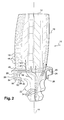
- FIG. 1 and 2 is shown a blade 10 of a high-pressure stage of a gas turbine, in particular a turbojet engine.
- This blade 10 comprises a blade formed with an extrados 12 or convex outer surface and with a lower surface 14 or concave inner surface which are connected at their upstream ends by a leading edge 16 and at their downstream ends by a trailing edge 18 of the gas flowing into the turbine.
- the blade is connected by a substantially rectangular transverse platform 20 to a blade root 22 by means of which the blade 10 is mounted on a disc (not shown) of the rotor of the gas turbine, by fitting of this foot 22 into a correspondingly shaped cavity of the periphery of the rotor disc.
- this male / female fitting which is fir type in the example shown, the blade 10 is retained radially on the rotor disc.
- Other means are provided for axially locking the root 22 of the blade 10 in the cavity of the disc.
- Each rotor disk comprises a plurality of vanes 10 regularly distributed on its outer periphery.
- the platform 20 is also connected to the blade root 22 by reinforcing webs called stiffeners 24, 26 which extend on the opposite side to the blade at the upstream and downstream ends of the platform 20, respectively, substantially perpendicular to the platform 20 and transversely or circumferentially with respect to the axis of rotation when the blade 10 is mounted on a rotor disc.
- the downstream stiffener 26 extends under the junction between the trailing edge 18 and the platform 20 and is connected to the blade root 22. Its lateral edge 28 substantially perpendicular to the platform 10 connects its radially inner edge 30 to a lateral edge platform 20 at the junction between the trailing edge 18 and the platform 20.
- the upstream and downstream stiffeners 24, 26 stiffen the platform 20 and prevent it from bending outwards about an axis parallel to the axis of rotation, and delimit between them a housing of a sealing jacket (not shown) which is arranged under the platform 20 and which extends between this blade 10 and an adjacent blade of the rotor disc.
- sealing sleeves prevent the passage of gas or air from the inner part of the turbine radially outwards between the platforms 20 of the adjacent blades, and conversely prevent the passage of gas or air from the outside towards the inner part of the turbine between the platforms 20 of the adjacent blades.
- the air of the inner part engages in orifices 32 of the end face of the blade root 22 and circulates in supply ducts 34 formed in the blade root 22 and extending into the airfoil. dawn 10, as indicated by dashed lines in Figure 2, these ducts being substantially parallel to the longitudinal axis 44 of the blade 10 and for cooling thereof.
- the circulation of air in the supply ducts is schematically represented by dashed arrows.
- the channel 34 located near the trailing edge 18 of the blade 10 feeds air discharge slots 46, shown in FIG. 1 and delimited in FIG. 2 by dashed lines formed on a portion of the underside. 14 near the trailing edge 18 and oriented substantially perpendicular to the longitudinal axis 44 of the blade 10 and parallel to the platform 20.
- the cooling air exiting through the slots 46 of the trailing edge 18 can not cool the connection 48 between the trailing edge 18 and the platform 20, which is in contact with the hot gases and is subjected to thermal stresses important.
- the invention provides for reducing these constraints by reducing the vertical thermal gradient between the downstream stiffener 26 and the connection 48 of the trailing edge 18 to the platform 20.
- a cavity 50 is formed in the stiffener 26, substantially in line with the trailing edge 18, and communicates with a duct 34 for supplying cooling air and with means for outputting the cooling air.
- the cavity 50 has a substantially parallelepiped shape with an inner edge 52 near the inner edge 30 of the stiffener 26 and substantially parallel thereto, a side edge 54 near the edge lateral 28 of the stiffener 26 and substantially parallel thereto, and an outer edge 56 substantially adjacent to the platform 20.
- the cavity 50 is directly connected to the conduit 34 for supplying the exhaust slots 46 with cooling air.
- the cavity 50 is connected to the outside by one or more orifices 58 opening downstream under the platform, which make it possible to ensure a continuous flow of air inside the cavity 50 and to cool the material located between this cavity 50 and the connection 48 of the trailing edge 18 to the platform 20.
- the circulation of the air in the cavity 50 and its outlet through the orifices 58 carries out a transfer and a heat discharge from the material between the cavity 50 and the connection 48 of the trailing edge 18, and cools this connection 48 by conduction.
- These orifices 58 may be of any shape and size. They can be formed on the downstream face of the stiffener 26.
- the cavity 50 has a length of about 5 to 6 millimeters in transverse or circumferential dimension, a height of about 3 millimeters along the axis 44 of dawn, and a thickness of 1 millimeter or less, for example about 0.8 millimeters, along the axis of rotation.
- This cavity 50 is advantageously made of foundry. In order not to weaken the downstream stiffener 26 of the blade 10, the thickness thereof can be increased, the increase in mass due to this increase in thickness being compensated for by the formation of the cavity 50.
- the orifices 58 are made of foundry, by laser drilling or electroerosion, the laser drilling techniques and EDM being substituted for the foundry for the production of orifices with a diameter less than about 0.6 millimeter.
Abstract
Description
La présente invention concerne une aube de rotor d'une turbine à gaz, en particulier d'une turbine haute-pression de turboréacteur.The present invention relates to a rotor blade of a gas turbine, in particular a high-pressure turbojet turbine.
De façon connue, une aube de rotor d'une turbine à gaz comprend une pale formée avec un extrados ou surface extérieure convexe et avec un intrados ou surface intérieure concave, reliés à leurs extrémités amont par un bord d'attaque et à leurs extrémités aval par un bord de fuite des gaz. La pale est raccordée par une plateforme à un pied d'aube du type en queue d'aronde, en sapin ou analogue, destiné à être inséré dans une cavité correspondante d'un disque de rotor de la turbine à gaz. Au moins un voile de renfort appelé « raidisseur » est formé à l'extrémité aval de la plateforme du côté opposé à la pale et s'étend transversalement en étant raccordé au pied d'aube.In known manner, a rotor blade of a gas turbine comprises a blade formed with an extrados or convex outer surface and with a concave inner surface or inner surface, connected at their upstream ends by a leading edge and at their downstream ends. by a trailing edge of the gases. The blade is connected by a platform to a blade root dovetail, fir or the like, intended to be inserted into a corresponding cavity of a rotor disc of the gas turbine. At least one reinforcing web called "stiffener" is formed at the downstream end of the platform on the side opposite to the blade and extends transversely while being connected to the blade root.
L'aube comprend également des moyens de refroidissement par circulation d'un fluide tel que l'air dans des conduits formés de fonderie à l'intérieur de la pale et du pied d'aube. L'air de refroidissement sort notamment par des fentes d'évacuation qui débouchent vers l'aval le long du bord de fuite et qui sont orientées de façon sensiblement perpendiculaire à l'axe longitudinal de l'aube et parallèle à la plateforme.The blade also comprises cooling means by circulating a fluid such as air in ducts formed of foundry inside the blade and the blade root. The cooling air exits in particular through discharge slots which open downstream along the trailing edge and which are oriented substantially perpendicular to the longitudinal axis of the blade and parallel to the platform.
La zone de raccordement du bord de fuite à la plateforme se trouve entre une fente d'évacuation d'air de refroidissement et le raidisseur, dont la partie radialement interne est refroidie par contact avec l'air de refroidissement. Cette zone de raccordement, en contact avec les gaz chauds passant dans la turbine, est soumise à des contraintes thermiques intenses qui provoquent la formation de criques susceptibles de détruire l'aube et aussi la turbine.The connection area of the trailing edge to the platform is between a cooling air discharge slot and the stiffener, the radially inner portion is cooled by contact with the cooling air. This connection zone, in contact with the hot gases passing through the turbine, is subjected to intense thermal stresses which cause the formation of cracks likely to destroy the blade and also the turbine.
On a déjà proposé de refroidir cette zone de raccordement par un écoulement d'air sortant par des orifices formés dans la plateforme et débouchant sur l'extrados mais cette solution n'est pas mécaniquement satisfaisante.It has already been proposed to cool this connection area by an outgoing air flow through orifices formed in the platform and opening on the extrados but this solution is not mechanically satisfactory.
L'invention a notamment pour but d'apporter une solution simple, économique et efficace à ce problème.The invention aims in particular to provide a simple, economical and effective solution to this problem.
Elle a pour objet une aube du type précité dans laquelle on refroidit la zone de raccordement entre le bord de fuite et la plateforme par limitation du gradient thermique entre cette zone de raccordement et le raidisseur.It relates to a blade of the aforementioned type in which the connection zone between the trailing edge and the platform is cooled by limiting the thermal gradient between this connection zone and the stiffener.
Elle propose à cet effet une aube de rotor d'une turbine à gaz, en particulier de turboréacteur, comprenant une pale, une plateforme raccordant la pale à un pied d'aube et au moins un raidisseur formé par un voile plan s'étendant depuis la plateforme du côté opposé à la pale et passant sous un bord de fuite de la pale, et des conduits de circulation d'un fluide de refroidissement formés dans la pale et dans le pied d'aube, caractérisée en ce qu'elle comprend également des moyens de refroidissement formés dans une partie du raidisseur adjacente à la plateforme et située sensiblement dans l'alignement du bord de fuite de la pale.To this end, it proposes a rotor blade of a gas turbine, in particular a turbojet, comprising a blade, a platform connecting the blade to a blade root and at least one stiffener formed by a planar web extending from the platform on the side opposite the blade and passing under a trailing edge of the blade, and cooling fluid circulation ducts formed in the blade and in the blade root, characterized in that it also comprises cooling means formed in a portion of the stiffener adjacent the platform and located substantially in alignment with the trailing edge of the blade.
Avantageusement, ces moyens de refroidissement comprennent une cavité formée dans le raidisseur et raccordée à un conduit d'alimentation passant dans le pied d'aube et à au moins un orifice de sortie de fluide de refroidissement débouchant vers l'aval sous la plateforme.Advantageously, these cooling means comprise a cavity formed in the stiffener and connected to a supply duct passing through the blade root and at least one cooling fluid outlet opening opening downstream under the platform.
La cavité de refroidissement formée dans le raidisseur sensiblement au droit du bord de fuite permet de refroidir la matière située entre cette cavité et le raccordement du bord de fuite à la plateforme. Cela se traduit par une réduction sensible du gradient thermique entre ce raccordement et le raidisseur et par une réduction concomitante des risques de formation de criques au raccordement du bord de fuite à la plateforme.The cooling cavity formed in the stiffener substantially to the right of the trailing edge to cool the material between the cavity and the connection of the trailing edge to the platform. This results in a significant reduction in the thermal gradient between this connection and the stiffener and in a concomitant reduction in the risk of formation of cracks at the connection of the trailing edge to the platform.
Le ou les orifices de sortie de la cavité sont avantageusement sensiblement parallèles au bord de fuite. Ils permettent une sortie du fluide de refroidissement circulant dans la cavité du raidisseur sans perturber l'écoulement des gaz quittant l'aube.The outlet or openings of the cavity are advantageously substantially parallel to the trailing edge. They allow an output of the cooling fluid circulating in the stiffener cavity without disturbing the flow of gases leaving the blade.
La cavité du raidisseur est réalisable de fonderie avec les conduits de circulation du fluide de refroidissement et les orifices de sortie de la cavité sont également obtenus de fonderie quand ils ont un diamètre supérieur ou égal à environ 0,6 millimètre, ou sont réalisés par perçage laser ou par électroérosion quand ils ont un diamètre plus faible.The stiffener cavity is realizable from foundry with ducts coolant circulation and the cavity outlet ports are also obtained by casting when they have a diameter greater than or equal to about 0.6 millimeters, or are made by laser drilling or by electro-erosion when they have a smaller diameter .
Pour faciliter la formation de cette cavité par fonderie, on peut donner au raidisseur une épaisseur légèrement supérieure à celle normalement prévue, l'augmentation de masse due à cette augmentation d'épaisseur étant compensée par la formation de la cavité.To facilitate the formation of this cavity by casting, the stiffener can be given a thickness slightly greater than that normally expected, the increase in mass due to this increase in thickness being compensated for by the formation of the cavity.
L'invention propose également une turbine de turboréacteur, caractérisée en ce qu'elle comprend une pluralité d'aubes du type précité dont les raidisseurs sont formés avec des cavités de refroidissement sensiblement au droit des bords de fuite des aubes.The invention also proposes a turbojet turbine, characterized in that it comprises a plurality of blades of the above-mentioned type, the stiffeners of which are formed with cooling cavities substantially in line with the trailing edges of the vanes.
L'invention concerne encore un turboréacteur, caractérisé en ce qu'il comprend une turbine telle que décrite ci-dessus.The invention also relates to a turbojet, characterized in that it comprises a turbine as described above.
D'autres avantages et caractéristiques de l'invention apparaîtront à la lecture de la description suivante faite à titre d'exemple non limitatif et en référence aux dessins annexés dans lesquels :
- la figure 1 est une vue schématique en perspective d'une aube de turbine selon l'invention, vue du côté amont ;
- la figure 2 est une vue schématique en perspective de l'aube de turbine de la figure 1, vue du côté aval.
- Figure 1 is a schematic perspective view of a turbine blade according to the invention, seen from the upstream side;
- Figure 2 is a schematic perspective view of the turbine blade of Figure 1, seen from the downstream side.
En figures 1 et 2 est représentée une aube 10 d'un étage haute-pression d'une turbine à gaz, en particulier d'un turboréacteur. Cette aube 10 comprend une pale formée avec un extrados 12 ou surface extérieure convexe et avec un intrados 14 ou surface intérieure concave qui sont reliés à leurs extrémités amont par un bord d'attaque 16 et à leurs extrémités aval par un bord 18 de fuite des gaz qui s'écoulent dans la turbine.In Figures 1 and 2 is shown a
La pale est reliée par une plateforme transversale 20 sensiblement rectangulaire à un pied d'aube 22 au moyen duquel l'aube 10 est montée sur un disque (non représenté) du rotor de la turbine à gaz, par emmanchement de ce pied 22 dans une cavité de forme correspondante de la périphérie du disque de rotor. Grâce à cet emmanchement mâle / femelle, qui est du type en sapin dans l'exemple représenté, l'aube 10 est retenue radialement sur le disque de rotor. D'autres moyens sont prévus pour bloquer axialement le pied 22 de l'aube 10 dans la cavité du disque. Chaque disque de rotor comprend une pluralité d'aubes 10 réparties régulièrement sur sa périphérie externe.The blade is connected by a substantially rectangular
La plateforme 20 est également reliée au pied d'aube 22 par des voiles de renfort appelés raidisseurs 24, 26 qui s'étendent du côté opposé à la pale aux extrémités amont et aval de la plateforme 20, respectivement, de façon sensiblement perpendiculaire à la plateforme 20 et transversalement ou en direction circonférentielle par rapport à l'axe de rotation lorsque l'aube 10 est montée sur un disque de rotor.The
Le raidisseur aval 26 s'étend sous la jonction entre le bord de fuite 18 et la plateforme 20 et est relié au pied d'aube 22. Son bord latéral 28 sensiblement perpendiculaire à la plateforme 10 relie son bord radialement interne 30 à un bord latéral de la plateforme 20 au niveau de la jonction entre le bord de fuite 18 et la plateforme 20.The
Les raidisseurs amont et aval 24, 26 rigidifient la plateforme 20 et l'empêchent de fléchir vers l'extérieur autour d'un axe parallèle à l'axe de rotation, et délimitent entre eux un logement d'une chemise d'étanchéité (non représentée) qui est agencée sous la plateforme 20 et qui s'étend entre cette aube 10 et une aube adjacente du disque de rotor.The upstream and
Ces chemises d'étanchéité empêchent le passage de gaz ou d'air depuis la partie interne de la turbine radialement vers l'extérieur entre les plates-formes 20 des aubes adjacentes, et inversement empêchent le passage de gaz ou d'air depuis l'extérieur vers la partie interne de la turbine entre les plates-formes 20 des aubes adjacentes.These sealing sleeves prevent the passage of gas or air from the inner part of the turbine radially outwards between the
L'air de la partie interne s'engage dans des orifices 32 de la face d'extrémité du pied d'aube 22 et circule dans des conduits d'alimentation 34 formés dans le pied d'aube 22 et se prolongeant dans la pale de l'aube 10, comme indiqué par des lignes en pointillés en figure 2, ces conduits étant sensiblement parallèles à l'axe longitudinal 44 de l'aube 10 et servant au refroidissement de celle-ci. La circulation de l'air dans les conduits d'alimentation est schématiquement représentée par des flèches en pointillés.The air of the inner part engages in
Le canal 34 situé à proximité du bord de fuite 18 de l'aube 10 alimente des fentes 46 d'évacuation d'air, représentées en figure 1 et délimitées en figure 2 par des lignes en pointillés, formées sur une partie de l'intrados 14 proche du bord de fuite 18 et orientées de façon sensiblement perpendiculaire à l'axe longitudinal 44 de l'aube 10 et parallèle à la plateforme 20.The
En fonctionnement, l'air de refroidissement sortant par les fentes 46 du bord de fuite 18 ne peut refroidir le raccordement 48 entre le bord de fuite 18 et la plateforme 20, qui est en contact avec les gaz chauds et est soumis à des contraintes thermiques importantes. L'invention prévoit de réduire ces contraintes par réduction du gradient thermique vertical entre le raidisseur aval 26 et le raccordement 48 du bord de fuite 18 à la plateforme 20. Pour cela, une cavité 50 est formée dans le raidisseur 26, sensiblement au droit du bord de fuite 18, et communique avec un conduit 34 d'alimentation en air de refroidissement et avec des moyens de sortie de l'air de refroidissement.In operation, the cooling air exiting through the
Dans l'exemple de réalisation des figures 1 et 2, la cavité 50 a une forme sensiblement parallélépipédique avec un bord interne 52 à proximité du bord interne 30 du raidisseur 26 et sensiblement parallèle à celui-ci, un bord latéral 54 à proximité du bord latéral 28 du raidisseur 26 et sensiblement parallèle à celui-ci, et un bord externe 56 sensiblement adjacent à la plateforme 20. La cavité 50 est reliée directement au conduit 34 d'alimentation des fentes d'évacuation 46 en air de refroidissement.In the embodiment of Figures 1 and 2, the
La cavité 50 est reliée à l'extérieur par un ou plusieurs orifices 58 débouchant vers l'aval sous la plateforme, qui permettent d'assurer une circulation continue d'air à l'intérieur de la cavité 50 et de refroidir la matière située entre cette cavité 50 et le raccordement 48 du bord de fuite 18 à la plateforme 20. La circulation de l'air dans la cavité 50 et sa sortie par les orifices 58 réalise un transfert et une évacuation de chaleur à partir de la matière entre la cavité 50 et le raccordement 48 du bord de fuite 18, et refroidit ce raccordement 48 par conduction.The
Ces orifices 58 peuvent être de formes et de dimensions quelconques. Ils peuvent être formés sur la face aval du raidisseur 26.These
Typiquement, pour une aube de turbine haute-pression d'environ 50 millimètres de hauteur, la cavité 50 a une longueur de 5 à 6 millimètres environ en dimension transversale ou circonférentielle, une hauteur de 3 millimètres environ le long de l'axe 44 de l'aube, et une épaisseur de 1 millimètre ou moins, par exemple de 0,8 millimètre environ, le long de l'axe de rotation.Typically, for a high pressure turbine blade of about 50 millimeters in height, the
Cette cavité 50 est réalisée avantageusement de fonderie. Afin de ne pas fragiliser le raidisseur aval 26 de l'aube 10, l'épaisseur de celui-ci peut être augmentée, l'augmentation de masse due à cette augmentation d'épaisseur étant compensée par la formation de la cavité 50.This
Les orifices 58 sont réalisés de fonderie, par perçage laser ou par électroérosion, les techniques de perçage laser et de l'électroérosion étant substituées à la fonderie pour la réalisation d'orifices de diamètre inférieur à 0,6 millimètre environ.The
Claims (8)
Applications Claiming Priority (1)
| Application Number | Priority Date | Filing Date | Title |
|---|---|---|---|
| FR0411436A FR2877034B1 (en) | 2004-10-27 | 2004-10-27 | ROTOR BLADE OF A GAS TURBINE |
Publications (3)
| Publication Number | Publication Date |
|---|---|
| EP1653047A2 true EP1653047A2 (en) | 2006-05-03 |
| EP1653047A3 EP1653047A3 (en) | 2011-09-07 |
| EP1653047B1 EP1653047B1 (en) | 2015-04-29 |
Family
ID=34952822
Family Applications (1)
| Application Number | Title | Priority Date | Filing Date |
|---|---|---|---|
| EP20050292209 Active EP1653047B1 (en) | 2004-10-27 | 2005-10-20 | Gas turbine rotor blade |
Country Status (4)
| Country | Link |
|---|---|
| US (1) | US7497661B2 (en) |
| EP (1) | EP1653047B1 (en) |
| JP (1) | JP4663479B2 (en) |
| FR (1) | FR2877034B1 (en) |
Cited By (1)
| Publication number | Priority date | Publication date | Assignee | Title |
|---|---|---|---|---|
| EP2228518A3 (en) * | 2009-03-10 | 2014-01-01 | Honeywell International Inc. | Cooled turbine blade platform |
Families Citing this family (12)
| Publication number | Priority date | Publication date | Assignee | Title |
|---|---|---|---|---|
| US8133024B1 (en) | 2009-06-23 | 2012-03-13 | Florida Turbine Technologies, Inc. | Turbine blade with root corner cooling |
| US8550783B2 (en) | 2011-04-01 | 2013-10-08 | Alstom Technology Ltd. | Turbine blade platform undercut |
| JP2011241836A (en) * | 2011-08-02 | 2011-12-01 | Mitsubishi Heavy Ind Ltd | Platform cooling structure of gas turbine moving blade |
| CN102418562B (en) * | 2011-08-15 | 2014-04-02 | 清华大学 | Fiber winding prestress turbine rotor |
| US8870525B2 (en) | 2011-11-04 | 2014-10-28 | General Electric Company | Bucket assembly for turbine system |
| US8840370B2 (en) | 2011-11-04 | 2014-09-23 | General Electric Company | Bucket assembly for turbine system |
| US8845289B2 (en) | 2011-11-04 | 2014-09-30 | General Electric Company | Bucket assembly for turbine system |
| US8974182B2 (en) * | 2012-03-01 | 2015-03-10 | General Electric Company | Turbine bucket with a core cavity having a contoured turn |
| EP2823152A1 (en) | 2012-05-08 | 2015-01-14 | Siemens Aktiengesellschaft | Turbine rotor blade and axial rotor blade section for a gas turbine |
| CN105855468A (en) * | 2016-04-13 | 2016-08-17 | 东方电气集团东方汽轮机有限公司 | Ceramic shell manufacturing method and method for manufacturing ceramic shell of turbine blade |
| US11021961B2 (en) | 2018-12-05 | 2021-06-01 | General Electric Company | Rotor assembly thermal attenuation structure and system |
| CN112459849B (en) * | 2020-10-27 | 2022-08-30 | 哈尔滨广瀚燃气轮机有限公司 | Cooling structure for turbine blade of gas turbine |
Citations (3)
| Publication number | Priority date | Publication date | Assignee | Title |
|---|---|---|---|---|
| FR2457967A1 (en) | 1979-06-01 | 1980-12-26 | Gen Electric | REFRIGERANT DISTRIBUTION SYSTEM FOR GAS TURBINE BLADE |
| US6120249A (en) | 1994-10-31 | 2000-09-19 | Siemens Westinghouse Power Corporation | Gas turbine blade platform cooling concept |
| EP1122405A2 (en) | 2000-02-02 | 2001-08-08 | General Electric Company | Gas turbine bucket cooling circuit |
Family Cites Families (17)
| Publication number | Priority date | Publication date | Assignee | Title |
|---|---|---|---|---|
| JPS5979006A (en) * | 1982-10-27 | 1984-05-08 | Hitachi Ltd | Air cooling blade of gas turbine |
| WO1996006266A1 (en) * | 1994-08-24 | 1996-02-29 | Westinghouse Electric Corporation | Gas turbine blade with cooled platform |
| JP3758792B2 (en) * | 1997-02-25 | 2006-03-22 | 三菱重工業株式会社 | Gas turbine rotor platform cooling mechanism |
| JP3316418B2 (en) * | 1997-06-12 | 2002-08-19 | 三菱重工業株式会社 | Gas turbine cooling blade |
| CA2262064C (en) * | 1998-02-23 | 2002-09-03 | Mitsubishi Heavy Industries, Ltd. | Gas turbine moving blade platform |
| JP3426952B2 (en) * | 1998-03-03 | 2003-07-14 | 三菱重工業株式会社 | Gas turbine blade platform |
| US6190130B1 (en) * | 1998-03-03 | 2001-02-20 | Mitsubishi Heavy Industries, Ltd. | Gas turbine moving blade platform |
| CA2231988C (en) * | 1998-03-12 | 2002-05-28 | Mitsubishi Heavy Industries, Ltd. | Gas turbine blade |
| US6210111B1 (en) * | 1998-12-21 | 2001-04-03 | United Technologies Corporation | Turbine blade with platform cooling |
| KR100694370B1 (en) * | 1999-05-14 | 2007-03-12 | 제너럴 일렉트릭 캄파니 | Apparatus and methods for relieving thermally induced stresses in inner and outer bands of thermally cooled turbine nozzle stages |
| FR2835015B1 (en) * | 2002-01-23 | 2005-02-18 | Snecma Moteurs | HIGH-PRESSURE TURBINE MOBILE TURBINE WITH IMPROVED THERMAL BEHAVIOR LEAKAGE EDGE |
| GB2395987B (en) * | 2002-12-02 | 2005-12-21 | Alstom | Turbine blade with cooling bores |
| JP3776897B2 (en) * | 2003-07-31 | 2006-05-17 | 三菱重工業株式会社 | Gas turbine rotor platform cooling mechanism |
| US6923616B2 (en) * | 2003-09-02 | 2005-08-02 | General Electric Company | Methods and apparatus for cooling gas turbine engine rotor assemblies |
| US6945749B2 (en) * | 2003-09-12 | 2005-09-20 | Siemens Westinghouse Power Corporation | Turbine blade platform cooling system |
| US7097417B2 (en) * | 2004-02-09 | 2006-08-29 | Siemens Westinghouse Power Corporation | Cooling system for an airfoil vane |
| GB0405679D0 (en) * | 2004-03-13 | 2004-04-21 | Rolls Royce Plc | A mounting arrangement for turbine blades |
-
2004
- 2004-10-27 FR FR0411436A patent/FR2877034B1/en active Active
-
2005
- 2005-10-20 EP EP20050292209 patent/EP1653047B1/en active Active
- 2005-10-25 JP JP2005309403A patent/JP4663479B2/en active Active
- 2005-10-25 US US11/257,151 patent/US7497661B2/en active Active
Patent Citations (3)
| Publication number | Priority date | Publication date | Assignee | Title |
|---|---|---|---|---|
| FR2457967A1 (en) | 1979-06-01 | 1980-12-26 | Gen Electric | REFRIGERANT DISTRIBUTION SYSTEM FOR GAS TURBINE BLADE |
| US6120249A (en) | 1994-10-31 | 2000-09-19 | Siemens Westinghouse Power Corporation | Gas turbine blade platform cooling concept |
| EP1122405A2 (en) | 2000-02-02 | 2001-08-08 | General Electric Company | Gas turbine bucket cooling circuit |
Cited By (1)
| Publication number | Priority date | Publication date | Assignee | Title |
|---|---|---|---|---|
| EP2228518A3 (en) * | 2009-03-10 | 2014-01-01 | Honeywell International Inc. | Cooled turbine blade platform |
Also Published As
| Publication number | Publication date |
|---|---|
| EP1653047B1 (en) | 2015-04-29 |
| JP2006125402A (en) | 2006-05-18 |
| EP1653047A3 (en) | 2011-09-07 |
| JP4663479B2 (en) | 2011-04-06 |
| US20060088416A1 (en) | 2006-04-27 |
| US7497661B2 (en) | 2009-03-03 |
| FR2877034A1 (en) | 2006-04-28 |
| FR2877034B1 (en) | 2009-04-03 |
Similar Documents
| Publication | Publication Date | Title |
|---|---|---|
| EP1653047B1 (en) | Gas turbine rotor blade | |
| EP1593814B1 (en) | Feather seal configuration for a gas turbine shroud | |
| CA2550442C (en) | Cooling circuits for turbine moving blade | |
| EP1736636B1 (en) | Hollow turbine blade | |
| CA2652679C (en) | Blades for turbomachine impeller, with a groove for cooling | |
| EP1586743B1 (en) | Turbine shroud | |
| FR2715693A1 (en) | Fixed or mobile turbine-cooled blade. | |
| EP1630350B1 (en) | Rotor blade of a compressor or a gas turbine | |
| EP1790819A1 (en) | Cooling circuit for a turbine blade | |
| FR2974387A1 (en) | TURBINE WHEEL FOR A TURBOMACHINE | |
| CA2619299A1 (en) | Turbomachine fan rotor disc | |
| FR2981979A1 (en) | TURBINE WHEEL FOR A TURBOMACHINE | |
| WO2015162389A1 (en) | Turbomachine turbine blade comprising a cooling circuit with improved homogeneity | |
| WO2012013892A1 (en) | Inter-vane seal for a wheel of a turbine or a turbomachine compressor | |
| EP1630351B1 (en) | Blade for a compressor or a gas turbine | |
| FR2968707A1 (en) | STEAM TURBINE AND COOLING CIRCUIT FOR ROTOR DRUM | |
| CA2456705C (en) | Annular platform for distributor of low-pressure turbine of jet engine | |
| EP3377731B1 (en) | Blade equipped with a cooling system, associated guide vanes assembly and associated turbomachine | |
| FR2974840A1 (en) | TURBINE DISPENSER IN A TURBOMACHINE | |
| EP3712378A1 (en) | Turbine engine blade comprising deflectors in an internal cooling cavity | |
| FR3028494A1 (en) | TURBOMACHINE BLADE, COMPRISING PONTETS EXTENDING FROM THE WALL OF INTRADOS TO THE WALL OF EXTRADOS | |
| WO2020193912A1 (en) | Turbine engine vane equipped with a cooling circuit and lost-wax method for manufacturing such a vane | |
| EP3867499A1 (en) | Turbine engine blade with improved cooling | |
| EP3942158A1 (en) | Turbine engine blade provided with an optimised cooling circuit | |
| FR3127018A1 (en) | Moving blade for a turbomachine turbine, having a design improving the sealing of the inter-blade cavities |
Legal Events
| Date | Code | Title | Description |
|---|---|---|---|
| PUAI | Public reference made under article 153(3) epc to a published international application that has entered the european phase |
Free format text: ORIGINAL CODE: 0009012 |
|
| AK | Designated contracting states |
Kind code of ref document: A2 Designated state(s): AT BE BG CH CY CZ DE DK EE ES FI FR GB GR HU IE IS IT LI LT LU LV MC NL PL PT RO SE SI SK TR |
|
| AX | Request for extension of the european patent |
Extension state: AL BA HR MK YU |
|
| PUAL | Search report despatched |
Free format text: ORIGINAL CODE: 0009013 |
|
| AK | Designated contracting states |
Kind code of ref document: A3 Designated state(s): AT BE BG CH CY CZ DE DK EE ES FI FR GB GR HU IE IS IT LI LT LU LV MC NL PL PT RO SE SI SK TR |
|
| AX | Request for extension of the european patent |
Extension state: AL BA HR MK YU |
|
| RIC1 | Information provided on ipc code assigned before grant |
Ipc: F01D 5/08 20060101ALI20110801BHEP Ipc: F01D 5/18 20060101AFI20110801BHEP |
|
| 17P | Request for examination filed |
Effective date: 20120209 |
|
| AKX | Designation fees paid |
Designated state(s): DE FR GB |
|
| 17Q | First examination report despatched |
Effective date: 20120613 |
|
| GRAP | Despatch of communication of intention to grant a patent |
Free format text: ORIGINAL CODE: EPIDOSNIGR1 |
|
| INTG | Intention to grant announced |
Effective date: 20141117 |
|
| GRAS | Grant fee paid |
Free format text: ORIGINAL CODE: EPIDOSNIGR3 |
|
| GRAA | (expected) grant |
Free format text: ORIGINAL CODE: 0009210 |
|
| AK | Designated contracting states |
Kind code of ref document: B1 Designated state(s): DE FR GB |
|
| REG | Reference to a national code |
Ref country code: GB Ref legal event code: FG4D Free format text: NOT ENGLISH |
|
| REG | Reference to a national code |
Ref country code: DE Ref legal event code: R096 Ref document number: 602005046435 Country of ref document: DE Effective date: 20150603 |
|
| REG | Reference to a national code |
Ref country code: FR Ref legal event code: PLFP Year of fee payment: 11 |
|
| REG | Reference to a national code |
Ref country code: DE Ref legal event code: R097 Ref document number: 602005046435 Country of ref document: DE |
|
| PLBE | No opposition filed within time limit |
Free format text: ORIGINAL CODE: 0009261 |
|
| STAA | Information on the status of an ep patent application or granted ep patent |
Free format text: STATUS: NO OPPOSITION FILED WITHIN TIME LIMIT |
|
| 26N | No opposition filed |
Effective date: 20160201 |
|
| REG | Reference to a national code |
Ref country code: FR Ref legal event code: PLFP Year of fee payment: 12 |
|
| REG | Reference to a national code |
Ref country code: FR Ref legal event code: PLFP Year of fee payment: 13 |
|
| REG | Reference to a national code |
Ref country code: FR Ref legal event code: CD Owner name: SAFRAN AIRCRAFT ENGINES, FR Effective date: 20170719 |
|
| REG | Reference to a national code |
Ref country code: FR Ref legal event code: PLFP Year of fee payment: 14 |
|
| PGFP | Annual fee paid to national office [announced via postgrant information from national office to epo] |
Ref country code: GB Payment date: 20230920 Year of fee payment: 19 |
|
| PGFP | Annual fee paid to national office [announced via postgrant information from national office to epo] |
Ref country code: FR Payment date: 20230920 Year of fee payment: 19 |
|
| PGFP | Annual fee paid to national office [announced via postgrant information from national office to epo] |
Ref country code: DE Payment date: 20230920 Year of fee payment: 19 |