EP1652719A1 - Power-assisted differential assembly - Google Patents
Power-assisted differential assembly Download PDFInfo
- Publication number
- EP1652719A1 EP1652719A1 EP05109581A EP05109581A EP1652719A1 EP 1652719 A1 EP1652719 A1 EP 1652719A1 EP 05109581 A EP05109581 A EP 05109581A EP 05109581 A EP05109581 A EP 05109581A EP 1652719 A1 EP1652719 A1 EP 1652719A1
- Authority
- EP
- European Patent Office
- Prior art keywords
- pinion
- ring gear
- electric motor
- assembly
- operable
- Prior art date
- Legal status (The legal status is an assumption and is not a legal conclusion. Google has not performed a legal analysis and makes no representation as to the accuracy of the status listed.)
- Granted
Links
Images

Classifications
-
- B—PERFORMING OPERATIONS; TRANSPORTING
- B60—VEHICLES IN GENERAL
- B60K—ARRANGEMENT OR MOUNTING OF PROPULSION UNITS OR OF TRANSMISSIONS IN VEHICLES; ARRANGEMENT OR MOUNTING OF PLURAL DIVERSE PRIME-MOVERS IN VEHICLES; AUXILIARY DRIVES FOR VEHICLES; INSTRUMENTATION OR DASHBOARDS FOR VEHICLES; ARRANGEMENTS IN CONNECTION WITH COOLING, AIR INTAKE, GAS EXHAUST OR FUEL SUPPLY OF PROPULSION UNITS IN VEHICLES
- B60K1/00—Arrangement or mounting of electrical propulsion units
-
- B—PERFORMING OPERATIONS; TRANSPORTING
- B60—VEHICLES IN GENERAL
- B60K—ARRANGEMENT OR MOUNTING OF PROPULSION UNITS OR OF TRANSMISSIONS IN VEHICLES; ARRANGEMENT OR MOUNTING OF PLURAL DIVERSE PRIME-MOVERS IN VEHICLES; AUXILIARY DRIVES FOR VEHICLES; INSTRUMENTATION OR DASHBOARDS FOR VEHICLES; ARRANGEMENTS IN CONNECTION WITH COOLING, AIR INTAKE, GAS EXHAUST OR FUEL SUPPLY OF PROPULSION UNITS IN VEHICLES
- B60K17/00—Arrangement or mounting of transmissions in vehicles
- B60K17/02—Arrangement or mounting of transmissions in vehicles characterised by arrangement, location, or kind of clutch
-
- B—PERFORMING OPERATIONS; TRANSPORTING
- B60—VEHICLES IN GENERAL
- B60K—ARRANGEMENT OR MOUNTING OF PROPULSION UNITS OR OF TRANSMISSIONS IN VEHICLES; ARRANGEMENT OR MOUNTING OF PLURAL DIVERSE PRIME-MOVERS IN VEHICLES; AUXILIARY DRIVES FOR VEHICLES; INSTRUMENTATION OR DASHBOARDS FOR VEHICLES; ARRANGEMENTS IN CONNECTION WITH COOLING, AIR INTAKE, GAS EXHAUST OR FUEL SUPPLY OF PROPULSION UNITS IN VEHICLES
- B60K6/00—Arrangement or mounting of plural diverse prime-movers for mutual or common propulsion, e.g. hybrid propulsion systems comprising electric motors and internal combustion engines
- B60K6/20—Arrangement or mounting of plural diverse prime-movers for mutual or common propulsion, e.g. hybrid propulsion systems comprising electric motors and internal combustion engines the prime-movers consisting of electric motors and internal combustion engines, e.g. HEVs
- B60K6/22—Arrangement or mounting of plural diverse prime-movers for mutual or common propulsion, e.g. hybrid propulsion systems comprising electric motors and internal combustion engines the prime-movers consisting of electric motors and internal combustion engines, e.g. HEVs characterised by apparatus, components or means specially adapted for HEVs
- B60K6/36—Arrangement or mounting of plural diverse prime-movers for mutual or common propulsion, e.g. hybrid propulsion systems comprising electric motors and internal combustion engines the prime-movers consisting of electric motors and internal combustion engines, e.g. HEVs characterised by apparatus, components or means specially adapted for HEVs characterised by the transmission gearings
-
- B—PERFORMING OPERATIONS; TRANSPORTING
- B60—VEHICLES IN GENERAL
- B60K—ARRANGEMENT OR MOUNTING OF PROPULSION UNITS OR OF TRANSMISSIONS IN VEHICLES; ARRANGEMENT OR MOUNTING OF PLURAL DIVERSE PRIME-MOVERS IN VEHICLES; AUXILIARY DRIVES FOR VEHICLES; INSTRUMENTATION OR DASHBOARDS FOR VEHICLES; ARRANGEMENTS IN CONNECTION WITH COOLING, AIR INTAKE, GAS EXHAUST OR FUEL SUPPLY OF PROPULSION UNITS IN VEHICLES
- B60K6/00—Arrangement or mounting of plural diverse prime-movers for mutual or common propulsion, e.g. hybrid propulsion systems comprising electric motors and internal combustion engines
- B60K6/20—Arrangement or mounting of plural diverse prime-movers for mutual or common propulsion, e.g. hybrid propulsion systems comprising electric motors and internal combustion engines the prime-movers consisting of electric motors and internal combustion engines, e.g. HEVs
- B60K6/22—Arrangement or mounting of plural diverse prime-movers for mutual or common propulsion, e.g. hybrid propulsion systems comprising electric motors and internal combustion engines the prime-movers consisting of electric motors and internal combustion engines, e.g. HEVs characterised by apparatus, components or means specially adapted for HEVs
- B60K6/40—Arrangement or mounting of plural diverse prime-movers for mutual or common propulsion, e.g. hybrid propulsion systems comprising electric motors and internal combustion engines the prime-movers consisting of electric motors and internal combustion engines, e.g. HEVs characterised by apparatus, components or means specially adapted for HEVs characterised by the assembly or relative disposition of components
- B60K6/405—Housings
-
- B—PERFORMING OPERATIONS; TRANSPORTING
- B60—VEHICLES IN GENERAL
- B60K—ARRANGEMENT OR MOUNTING OF PROPULSION UNITS OR OF TRANSMISSIONS IN VEHICLES; ARRANGEMENT OR MOUNTING OF PLURAL DIVERSE PRIME-MOVERS IN VEHICLES; AUXILIARY DRIVES FOR VEHICLES; INSTRUMENTATION OR DASHBOARDS FOR VEHICLES; ARRANGEMENTS IN CONNECTION WITH COOLING, AIR INTAKE, GAS EXHAUST OR FUEL SUPPLY OF PROPULSION UNITS IN VEHICLES
- B60K6/00—Arrangement or mounting of plural diverse prime-movers for mutual or common propulsion, e.g. hybrid propulsion systems comprising electric motors and internal combustion engines
- B60K6/20—Arrangement or mounting of plural diverse prime-movers for mutual or common propulsion, e.g. hybrid propulsion systems comprising electric motors and internal combustion engines the prime-movers consisting of electric motors and internal combustion engines, e.g. HEVs
- B60K6/42—Arrangement or mounting of plural diverse prime-movers for mutual or common propulsion, e.g. hybrid propulsion systems comprising electric motors and internal combustion engines the prime-movers consisting of electric motors and internal combustion engines, e.g. HEVs characterised by the architecture of the hybrid electric vehicle
- B60K6/48—Parallel type
-
- B—PERFORMING OPERATIONS; TRANSPORTING
- B60—VEHICLES IN GENERAL
- B60K—ARRANGEMENT OR MOUNTING OF PROPULSION UNITS OR OF TRANSMISSIONS IN VEHICLES; ARRANGEMENT OR MOUNTING OF PLURAL DIVERSE PRIME-MOVERS IN VEHICLES; AUXILIARY DRIVES FOR VEHICLES; INSTRUMENTATION OR DASHBOARDS FOR VEHICLES; ARRANGEMENTS IN CONNECTION WITH COOLING, AIR INTAKE, GAS EXHAUST OR FUEL SUPPLY OF PROPULSION UNITS IN VEHICLES
- B60K17/00—Arrangement or mounting of transmissions in vehicles
- B60K17/04—Arrangement or mounting of transmissions in vehicles characterised by arrangement, location or kind of gearing
- B60K17/16—Arrangement or mounting of transmissions in vehicles characterised by arrangement, location or kind of gearing of differential gearing
-
- B—PERFORMING OPERATIONS; TRANSPORTING
- B60—VEHICLES IN GENERAL
- B60K—ARRANGEMENT OR MOUNTING OF PROPULSION UNITS OR OF TRANSMISSIONS IN VEHICLES; ARRANGEMENT OR MOUNTING OF PLURAL DIVERSE PRIME-MOVERS IN VEHICLES; AUXILIARY DRIVES FOR VEHICLES; INSTRUMENTATION OR DASHBOARDS FOR VEHICLES; ARRANGEMENTS IN CONNECTION WITH COOLING, AIR INTAKE, GAS EXHAUST OR FUEL SUPPLY OF PROPULSION UNITS IN VEHICLES
- B60K6/00—Arrangement or mounting of plural diverse prime-movers for mutual or common propulsion, e.g. hybrid propulsion systems comprising electric motors and internal combustion engines
- B60K6/20—Arrangement or mounting of plural diverse prime-movers for mutual or common propulsion, e.g. hybrid propulsion systems comprising electric motors and internal combustion engines the prime-movers consisting of electric motors and internal combustion engines, e.g. HEVs
- B60K6/42—Arrangement or mounting of plural diverse prime-movers for mutual or common propulsion, e.g. hybrid propulsion systems comprising electric motors and internal combustion engines the prime-movers consisting of electric motors and internal combustion engines, e.g. HEVs characterised by the architecture of the hybrid electric vehicle
- B60K6/48—Parallel type
- B60K2006/4808—Electric machine connected or connectable to gearbox output shaft
-
- Y—GENERAL TAGGING OF NEW TECHNOLOGICAL DEVELOPMENTS; GENERAL TAGGING OF CROSS-SECTIONAL TECHNOLOGIES SPANNING OVER SEVERAL SECTIONS OF THE IPC; TECHNICAL SUBJECTS COVERED BY FORMER USPC CROSS-REFERENCE ART COLLECTIONS [XRACs] AND DIGESTS
- Y02—TECHNOLOGIES OR APPLICATIONS FOR MITIGATION OR ADAPTATION AGAINST CLIMATE CHANGE
- Y02T—CLIMATE CHANGE MITIGATION TECHNOLOGIES RELATED TO TRANSPORTATION
- Y02T10/00—Road transport of goods or passengers
- Y02T10/60—Other road transportation technologies with climate change mitigation effect
- Y02T10/62—Hybrid vehicles
Definitions
- the clutch assembly 164 generally includes a clutch pack 190 and an actuator 192.
- the clutch pack 190 includes a series of first clutch plates 194 and a series of second clutch plates 196.
- the first clutch plates 194 are splined to the tail 170 of the second pinion 160 and the second clutch plates 196 are splined to the rotor 184.
- the first and second clutch plates 194 and 196 are interleaved with one another.
- the first and second clutch plates 194 and 196 are axially slidable along the third axis 175.
- the actuator 192 is operable to axially slide the second clutch plates 196 into engagement with the first clutch plates 194.
- the actuator 192 can be any conventional actuator.
- the controller 30 can increase the rotational speed of the second pinion 160 and/or increase the speed of the engine 16 to increase the rotational speed of the first pinion 110.
- the motor 162 can also be used to provide the entire driving force necessary to drive the ring gear 82 to propel the vehicle 10 from a standstill.
- the assembly 200 is a simplified version of assembly 26 and does not include the clutch assembly 164.
- the rotor 184' of the motor 162' is rotationally fixed to the tail 170' of the second pinion 160'. Therefore, rotation of the second pinion 160' by the ring gear 82 when the motor 162' is not activated causes the rotor 184' to rotate.
- Controller 30 is operable to allow motor 162' to rotate freely or to function as a generator to generate electricity.
Landscapes
- Engineering & Computer Science (AREA)
- Chemical & Material Sciences (AREA)
- Combustion & Propulsion (AREA)
- Transportation (AREA)
- Mechanical Engineering (AREA)
- Electric Propulsion And Braking For Vehicles (AREA)
- Retarders (AREA)
- Arrangement Of Transmissions (AREA)
- Hybrid Electric Vehicles (AREA)
- Control Of Vehicle Engines Or Engines For Specific Uses (AREA)
- Combined Controls Of Internal Combustion Engines (AREA)
- Gear Transmission (AREA)
Abstract
Description
- The present invention relates to automotive axle assemblies. In particular, the present invention relates to a differential carrier assembly having an electric drive assembly.
- Automobile manufacturers are increasingly offering for sale automobiles powered by electric motors. Electric motors provide numerous advantages when compared to traditional combustion engines. For example, electric motors typically operate more efficiently and emit fewer undesirable emissions to the environment. However, combustion engines generally outperform electric motors in numerous other performance categories and typically provide higher horsepower per pound when the weight of batteries are taken into consideration. Further, automobiles propelled by electric motors are generally more expensive than automobiles propelled by combustion engines and need to be recharged more often than a vehicle propelled by a combustion engine needs to be refueled. Therefore, in spite of the advantages associated with electric motors, consumers are generally reluctant to purchase motor vehicles propelled solely by electric motors.
- Accordingly, there is a need in the art for a motor vehicle that offers the advantages of an electric engine, such as increased efficiency, as well as the advantages of a combustion engine, such as reduced cost and enhanced performance.
- In one form, the present invention provides for an axle assembly for a motor vehicle. The assembly comprises a carrier housing and a differential assembly that is rotatably mounted to the carrier housing. A ring gear is fixed to the differential assembly for rotation therewith. A first pinion is in meshing engagement with the ring gear. The first pinion is adapted to be driven by a combustion engine and is operable to drive the ring gear. An electric drive assembly is mounted to the carrier housing. The electric drive assembly includes an electric motor and a second pinion. The second pinion is in meshing engagement with the ring gear. The second pinion is selectively driven by the electric motor and is operable to drive the ring gear.
- In another form, the present invention provides for an axle assembly for a motor vehicle. The axle assembly comprises a carrier housing and a ring gear rotatably mounted within the carrier housing. A first pinion is in meshing engagement with the ring gear and is operable to drive the ring gear. A second pinion is in meshing engagement with the ring gear. The second pinion is also operable to drive the ring gear. An electric motor is mounted to the carrier housing. A controller monitors the operating parameters of the motor vehicle. The controller selectively activates and deactivates the electric motor in response to the status of the operating parameters.
- In yet another form, the present invention provides for a method for propelling a motor vehicle having both an internal combustion engine and an electric motor. The internal combustion engine is selectively coupled to a ring gear. The ring gear is rotatably mounted within a carrier housing. The electric motor is selectively operable to provide drive torque to the ring gear. The method comprises the following steps: drivingly interconnecting the ring gear and the combustion engine; drivingly interconnecting the ring and the electric motor; monitoring predetermined operating parameters of the motor vehicle using a controller; and selectively activating and deactivating the electric motor based on the status of the predetermined operating parameters.
- Further areas of applicability of the present invention will become apparent from the detailed description provided hereinafter. It should be understood that the detailed description and specific examples, while indicating the preferred embodiment of the invention, are intended for purposes of illustration only and are not intended to limit the scope of the invention.
- The present invention will become more fully understood from the detailed description and the accompanying drawings, wherein:
- Figure 1 is a schematic illustration of a motor vehicle constructed in accordance with the teachings of the present invention;
- Figure 2 is a fragmentary perspective view of a portion of the motor vehicle of Figure 1, illustrating the rear axle in greater detail;
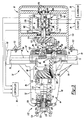
- Figure 3 is a section view of a carrier assembly of the motor vehicle of Figure 1 equipped with an electric drive assembly according to an embodiment of the present invention;
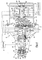
- Figure 4 is a section view of a carrier assembly of the motor vehicle of Figure 1 equipped with an electric drive assembly according to another embodiment of the present invention; and
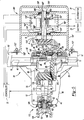
- Figure 5 is a section view of a carrier assembly of the motor vehicle of Figure 1 equipped with an electric drive assembly according to another embodiment of the present invention.
- The following description of the preferred embodiments is merely exemplary in nature and is in no way intended to limit the invention, its application, or uses.
- With reference to Figure 1, a vehicle having an axle assembly constructed in accordance with the teachings of the present invention is generally indicated by
reference numeral 10. Thevehicle 10 includes adriveline 12 drivable via a connection to apower train 14. Thepower train 14 includes acombustion engine 16 and atransmission 18. Thedriveline 12 includes adrive shaft 20, arear axle 22, and a plurality ofwheels 24. Therear axle 22 includes anelectric drive assembly 26. A power supply, such as analternator 28 or abattery 29, supplies electricity to theelectric drive assembly 26. Acontroller 30 monitors inputs from sensors 32 to determine various operating parameters of thevehicle 10, such as vehicle speed, engine revolutions per minute (RPM), ring gear speed, throttle position as indicated by the position of anaccelerator pedal 31, and other parameters as set forth below. Thecontroller 30 processes the information gained using the sensors 32 and, as described further below, operates theelectric drive assembly 26 based on this information. - Figures 2 and 3 depict the
rear axle 22 in greater detail.Rear axle 22 includes acarrier assembly 34, a leftaxle shaft assembly 36, and a rightaxle shaft assembly 38. Thecarrier assembly 34 includes acarrier housing 40, adifferential unit 42, and aninput shaft assembly 44. Thehousing 40 supports thedifferential unit 42 for rotation about afirst axis 46 and further supports theinput shaft assembly 44 for rotation about asecond axis 48 that is perpendicular to thefirst axis 46. - The
housing 40 is initially formed in a suitable casting process and thereafter machined as required. Thehousing 40 includes amain body 50 and apinion nose 52 extending from themain body 50. Thehousing 40 includes awall member 54 that defines acentral cavity 56 having aleft axle aperture 58, aright axle aperture 60, and afirst pinion aperture 62. - The left
axle shaft assembly 36 includes afirst axle tube 70 fixed to theleft axle aperture 58 and a first axle half-shaft 72 that is supported for rotation about thefirst axis 46 by thefirst axle tube 70. Similarly, rightaxle shaft assembly 38 includes asecond axle tube 74 that is fixed toright axle aperture 60 and which supports a second axle half-shaft 76 for rotation about thefirst axis 46. - Figure 3 depicts the
differential unit 42 being disposed within thecentral cavity 56 of themain body 50 of thehousing 40. Thedifferential unit 42 includes acase 80, aring gear 82 that is fixed for rotation with thecase 80, and agear set 84 that is disposed within thecase 80.Ring gear 82 includes a plurality ofteeth 83. The gear set 84 includes first and second side gears 86 and 88 and a pair of differential pinions 90.Differential pinions 90 are rotatably supported onpinion shafts 92 that are mounted to thecase 80. Thecase 80 includes a pair oftrunnions gear cavity 98. A pair of bearingassemblies trunnions first axis 46. - First
axle half shaft 72 and secondaxle half shaft 76 extend through left andright axle apertures first axis 46 with first and second side gears 86 and 88, respectively. Thecase 80 is operable to supportdifferential pinions 90 for rotation within thegear cavity 98 about one or more axes that are perpendicular to thefirst axis 46. The first and second side gears 86 and 88 each include a plurality ofteeth 104 that meshingly engageteeth 106 that are formed ondifferential pinions 90. - The
input shaft assembly 44 generally includes afirst input pinion 110, a propeller shaftcoupling flange assembly 112, and a pair ofconventional bearing assemblies assemblies housing 40 in a press-fit manner. The bearingassemblies housing 40 to support thefirst pinion 110 for rotation about thesecond axis 48. - The
first pinion 110 includes atail portion 118 and ahead portion 120 integrally formed with one another. Thehead portion 120 includes a plurality ofteeth 122. Theteeth 122 meshingly engage theteeth 83 of thering gear 82 to transfer torque from thepower train 14 to thedifferential unit 42. A plurality ofexternal splines 119 are formed on thetail portion 118. An externally threadedportion 121 is formed on a reduced diameter section at the end of thetail portion 118. - The
coupling flange assembly 112 generally includes apinion flange 124 and aseal assembly 126. Thepinion flange 124 includes aninternal spline 128 in engagement withexternal splines 119 of thefirst pinion 110. Anut 130 fixedly mounts thepinion flange 124 to the threadedportion 121 of thetail portion 118. At least a portion of thepinion flange 124 is located within thepinion nose 52. - The
seal 126 is mounted at thefirst pinion aperture 62 by any suitable mounting means. Theseal 126 includes anaperture 132 through which thefirst pinion 110 passes. Theseal 126 is any suitable seal operable to prevent the passage of foreign materials, such as dirt and fluids, from entering thehousing 40. - The
electric drive assembly 26 includes a support casing 150. The casing 150 can be integral with thecarrier housing 40 or secured to thecarrier housing 40 using any suitable fastening means. For example, and as illustrated in Figures 3 through 5, the casing 150 can be secured to thehousing 40 bybolts 152 that extend through anouter wall 154 of the casing and engage thewall member 54 of thehousing 40. The casing 150 can be secured to thehousing 40 at a variety of different locations, as long as cooperation between components of theelectric drive assembly 26 and thering gear 82 is possible. The casing 150 can be made from any number of suitable materials, such as aluminum, steel or composite material. - The
housing 40 includes anopening 156 to allow components of theelectric drive assembly 26 to cooperate with thering gear 82. Theopening 156 can be specifically formed to accommodate the position of theassembly 26 or theopening 156 can be a pre-existing opening, such as a conventional carrier cover pan opening as illustrated. When theopening 156 is the conventional cover pan opening, the casing 150 can be secured to thehousing 40 using the same bolt holes used to secure a conventional cover pan (not shown) to the cover pan opening. - The
electric drive assembly 26 depicted in Figure 3 generally comprises asecond pinion 160, anelectric motor 162, and aclutch assembly 164. Thesecond pinion 160 generally includes a secondpinion tail portion 170 and a secondpinion head portion 172. Thetail 170 of thesecond pinion 160 is integrally formed with thehead portion 172. Thehead portion 172 includes a plurality ofgear teeth 174. Thetail 170 is rotatably mounted in the support casing 150 on one ormore bearings 176 to permit rotation of thesecond pinion 160 about athird axis 175 that can be aligned with thesecond axis 48, as illustrated in Figure 3. Thesecond pinion 160 is mounted in a position such that theteeth 174 of thesecond pinion 160 are in meshing engagement with theteeth 83 of thering gear 82. Thegear teeth 174 can be of any suitable shape or size that allows the teeth to meshingly engage theteeth 83 of thering gear 82, which also can be of any suitable shape or size. Furthermore, as illustrated, theaxis 175 may be offset fromaxis 46 to form a hypoid gear arrangement. - The
motor 162 and the clutch 164 are both seated within amotor housing 178. Themotor housing 178 is rigidly coupled to an interior of the support casing 150 in any suitable manner. Themotor housing 178 can also be integral with the casing 150. Themotor housing 178 includes aninterior aperture 180 that extends through the approximate center of themotor housing 178. Thetail 170 extends through theinterior aperture 180. Themotor housing 178 also includes coolingfins 182. The coolingfins 182 are located on an outer surface of thehousing 178 to increase the surface area of themotor housing 178 and assist in cooling the components of thehousing 178, such as theelectric motor 162 and the clutch 164 assembly. - The
motor 162 is integral with or mounted within themotor housing 178 using any suitable mounting means. Themotor 162 can be any suitable electric motor. Themotor 162 includes arotor 184. Therotor 184 is generally cylindrical and has a center aperture. Therotor 184 is rotationally mounted within thehousing 178. Therotor 184 rotates about thethird axis 175. Thepinion tail 170 extends through the center aperture of therotor 184. Thus, therotor 184 may rotate about thepinion tail 170. Themotor 162 is powered by any suitable power source, such as thealternator 28 or thebattery 29. - The
clutch assembly 164 generally includes a clutch pack 190 and an actuator 192. The clutch pack 190 includes a series of first clutch plates 194 and a series of secondclutch plates 196. The first clutch plates 194 are splined to thetail 170 of thesecond pinion 160 and the secondclutch plates 196 are splined to therotor 184. The first and secondclutch plates 194 and 196 are interleaved with one another. The first and secondclutch plates 194 and 196 are axially slidable along thethird axis 175. The actuator 192 is operable to axially slide the secondclutch plates 196 into engagement with the first clutch plates 194. The actuator 192 can be any conventional actuator. For example, the actuator 192 can be a hydraulic actuator or an electric actuator, which could be powered by thealternator 28 or thebattery 29. When the first and secondclutch plates 194 and 196 engage each other, rotation of therotor 184 effectuates rotation of thesecond pinion 160. - The
controller 30 monitors various operating parameters of thevehicle 10 and controls the operation of theelectric drive assembly 26. Thecontroller 30 can by any suitable signal processing device or control device, such as a microcomputer. The controller receives inputs from various sensors 32, which monitor different parameters of thevehicle 10. The sensors 32 can each be any suitable conventional sensing device. Specifically, and as shown in Figures 1 and 3, thesensor 32A monitors the speed of theengine 16. Thesensor 32B monitors the revolutions of thedrive shaft 20 to determine the ground speed of thevehicle 10. Thesensor 32C monitors the rotational speed of thering gear 82. Thesensor 32D monitors the rotational speed of thesecond pinion 160. Thesensor 32E monitors the operation of theelectric motor 162, the position of the clutch 164, and the position of the actuator 192. Thesensor 32F monitors the throttle position as an indication of the amount of acceleration desired by the operator. Thecontroller 30 is also operable to send commands to theengine 16 and theelectric drive assembly 26 to control their operation. - The
controller 30 activates theelectric drive assembly 26 when certain predetermined operating conditions of themotor vehicle 10 are present. In some applications, thecontroller 30 is programmed to activate theelectric drive assembly 26 when thevehicle 10 is accelerating from a standstill, such as between 0 mph and 10 mph, and at highway cruising speeds, such as above 55 mph. However, thecontroller 30 can be programmed to activate theelectric drive assembly 26 in response to the occurrence of a variety of different conditions. - Operation of the
electric drive assembly 26 when thecontroller 30 is programmed to activate themotor 162 at lower speeds (speeds less than 10 mph) and highway cruising speeds (speeds greater than 55 mph) will now be described in detail. Ifvehicle 10 is at a stationary position, or rolling at less than 10 mph,sensor 32B sends a signal to thecontroller 30 as such.Controller 30 also receives a signal fromsensor 32F indicative of the throttle position. The controller then sends commands to themotor 162 and the actuator 192 to activate themotor 162 and the actuator 192 if vehicle acceleration is requested. Activation of themotor 162 causes therotor 184 to rotate about the third axis ofrotation 175. The activated actuator 192 axially slides the first clutch plates 194 and the secondclutch plates 196 into engagement to drivingly interconnect therotor 184 and thesecond pinion tail 170. Therefore, rotation of therotor 184 effectuates rotation of thesecond pinion 160. - The
controller 30 also controls the speed at which therotor 184 and thesecond pinion 160 rotate. During acceleration of thevehicle 10, thesecond pinion 160 exerts a driving force on thering gear 82 to supplement the driving force that thefirst pinion 110 exerts upon thering gear 82. This condition allows decreasing the output required by theengine 16. To properly operatemotor 162, thecontroller 30 identifies the speed of theengine 16, the speed of thering gear 82 and the position of the throttle. Use of themotor 162 in this manner to decrease the load on theengine 16 advantageously improves the fuel economy of thevehicle 10 and prolongs the life of theengine 16. - After the
controller 30 determines that the speed of thevehicle 10 is greater than 10 mph by processing inputs from thesensor 32B, thecontroller 30 sends a signal to themotor 162 to deactivate themotor 162. Even after themotor 162 is deactivated, thesecond pinion 160 continues to rotate due to the cooperation between thehead 172 and thering gear 82. At this time,motor 162 may be decoupled fromsecond pinion 160 or may remain coupled to provide braking. For example, thecontroller 30 may be programmed to deactivate actuator 192 to decouple thesecond pinion 160 from therotor 184. Alternatively, if thesecond pinion 160 and therotor 184 remain coupled, then rotation of the second pinion due to rotation of thering gear 82 results in rotation of therotor 184, thus causing themotor 162 to act as a generator. Electricity generated by themotor 162 can be transferred to thebattery 29 during a charging operation. If thesecond pinion 160 and therotor 184 are decoupled then thesecond pinion 160 freely spins and no electricity is generated. - The
electric drive assembly 26 can also serve as the sole source of propulsion for thevehicle 10. For example, after thevehicle 10 is propelled to a predetermined cruising speed by theengine 16, such as 55 mph, thecontroller 30 can activate theelectric motor 162 to rotate thesecond pinion 160 in the manner set forth above. Thecontroller 30 then commands theengine 16 to reduce its RPM output to idle and the rotational speed of thesecond pinion 160 is set to provide the entire driving force necessary to drive thering gear 82 and propel thevehicle 10. At idle, theengine 16 is still operable to maintain the power steering, power brakes, and other vehicle accessories, but uses far less fuel and improves the vehicle's fuel economy. To accelerate thevehicle 10 after theengine 16 is brought to idle, thecontroller 30 can increase the rotational speed of thesecond pinion 160 and/or increase the speed of theengine 16 to increase the rotational speed of thefirst pinion 110. Themotor 162 can also be used to provide the entire driving force necessary to drive thering gear 82 to propel thevehicle 10 from a standstill. - Figure 4 illustrates an electric drive assembly according to an additional embodiment at
reference numeral 200. Theelectric drive assembly 200 is similar to theelectric drive assembly 26 and like reference numbers are used to identify like elements of the embodiments with the like elements of theassembly 200 including the prime (') designation. The above description of the like elements and their operation equally applies to theassembly 200. - The
assembly 200 is a simplified version ofassembly 26 and does not include theclutch assembly 164. In theassembly 200, the rotor 184' of the motor 162' is rotationally fixed to the tail 170' of the second pinion 160'. Therefore, rotation of the second pinion 160' by thering gear 82 when the motor 162' is not activated causes the rotor 184' to rotate.Controller 30 is operable to allow motor 162' to rotate freely or to function as a generator to generate electricity. - Figure 5 illustrates an electric drive assembly according to an alternate embodiment at
reference numeral 300. Theelectric drive assembly 300 is similar to theelectric drive assemblies assembly 300 including the double prime (") designation. The above description of the like elements equally applies to theassembly 300. - The
assembly 300 is substantially similar to theassembly 200 except that theassembly 300 includes apinion actuator 302. Theactuator 302 can be any conventional actuator that is operable to linearly slide thesecond pinion 160" along thethird axis 175" between a first position A, in which thehead 172" meshingly engages thering gear 82, and a second position B, in which thehead 172" is spaced apart from thering gear 82. In this embodiment, when torque is required from themotor 162", thecontroller 30 checks the position of theactuator 302 using thesensor 32E to make sure that thesecond pinion 160" is at position A. If thesecond pinion 160" is not at position A then the controller activates theactuator 302 to move thesecond pinion 160" to position A. - When the
controller 30 determines that use of themotor 162" is not necessary, thecontroller 30 deactivates themotor 162". If thecontroller 30 determines that thebattery 29, or other device, needs to be recharged, thecontroller 30 keeps thesecond pinion 160" at position A so that rotation of thesecond pinion 160" by thering gear 82 will rotate therotor 184" and cause themotor 162" to generate electricity that can be stored by thebattery 29. If thecontroller 30 determines that themotor 162" does not need to be used to generate electricity, then thecontroller 30 signals theactuator 302 to move thesecond pinion 160" to position B so that thesecond pinion 160" is not in drivingly engaged with thering gear 82. Use of theassembly 300 is advantageous because thesecond pinion 160" can be moved from engagement with thering gear 82 when themotor 162" is not in use and, therefore, thesecond pinion 160" does not cause unnecessary drag on thering gear 82, which can negatively effect fuel economy. Theactuator 302 of theassembly 300 can also be provided in theassemblies second pinions 160 and 160' into and out of engagement with thering gear 82 as desired. - One of ordinary skill in the art will recognize that the
electric drive assemblies assemblies assemblies assemblies - Therefore, the electric drive assembly of the present invention is operable to increase the fuel economy of the
vehicle 10 and decrease the load on theengine 16 by driving asecond pinion 160 that is in cooperation with thering gear 82. The driving force exerted by thesecond pinion 160 replaces or supplements the driving force of thefirst pinion 110 and thus the output required of theengine 16 is decreased. Theelectric motor 162 may be in operation at all times or only at select times, such as during acceleration when the demands of theengine 16 are the greatest or during highway cruising speeds when theelectric motor 162 is capable of solely propelling thevehicle 10 with minimal performance loss. The electric drive assembly offers such advantages while still providing the user with the performance advantages of a traditional combustion engine. - Furthermore, the foregoing discussion discloses and describes merely exemplary embodiments of the present invention. One skilled in the art will readily recognize from such discussion, and from the accompanying drawings and claims, that various changes, modifications and variations may be made therein without department from the spirit and scope of the invention as defined in the following claims.
Claims (25)
- An axle assembly for a motor vehicle comprising:a carrier housing;a differential assembly rotatably mounted to said carrier housing;a ring gear fixed to said differential assembly for rotation therewith;a first pinion in meshing engagement with said ring gear, said first pinion being adapted to be driven by a combustion engine and operable to drive said ring gear; andan electric drive assembly mounted to said carrier housing, said electric drive assembly including:an electric motor; anda second pinion in meshing engagement with said ring gear, said second pinion being selectively driven by said electric motor and operable to drive said ring gear.
- The axle assembly of Claim 1, wherein said electric drive assembly further comprises a clutch assembly operable to selectively drivingly interconnect said electric motor and said second pinion.
- The axle assembly of Claim 2, further including an actuator being operable to selectively provide an application force to said clutch assembly to drivingly interconnect said electric motor and said second pinion.
- The axle assembly of any preceding claim, wherein said first pinion and said second pinion rotate about substantially the same axis of rotation.
- The axle assembly of any preceding claim, wherein said electric drive assembly is mounted to a cover pan opening of said carrier housing.
- The axle assembly of any preceding claim, further comprising a controller being operable to control the operation of said electric motor.
- The axle assembly of any preceding claim, wherein said electric motor selectively operates as a generator to generate electricity.
- The axle assembly of any preceding claim, wherein said electric motor includes a component that is fixed to said second pinion.
- The axle assembly of any preceding claim, wherein said second pinion is movable between a first position in which said second pinion drivingly engages said ring gear and a second position in which said second pinion is spaced apart from said ring gear.
- The axle assembly of any preceding claim further including first and second output shafts drivingly coupled to said differential assembly, said electric drive assembly being operable to transfer torque from said electric motor to said first and second output shafts.
- An axle assembly for a motor vehicle comprising:a carrier housing;a ring gear rotatably mounted within said carrier housing;a first pinion in meshing engagement with said ring gear and operable to drive said ring gear;an electric motor mounted to said carrier housing;a second pinion in meshing engagement with said ring gear, said second pinion being operable to drive said ring gear; anda controller monitoring operating parameters of the motor vehicle, said controller selectively activating and deactivating said electric motor in response to the status of the operating parameters.
- The axle assembly of Claim 11, wherein said second pinion is directly driven by said electric motor.
- The axle assembly of any preceding claims 11-12, wherein said first pinion and said second pinion rotate about the same axis.
- The axle assembly of any preceding claims 11-13, wherein said electric motor is mounted within a casing that is secured to a cover pan opening of said carrier housing.
- The axle assembly of any preceding claims 11-14, further comprising a clutch assembly operable to selectively drivingly interconnect said electric motor and said second pinion.
- The axle assembly of any preceding claims 11-15, further comprising an actuator operable to move said second pinion between a first position in which said second pinion drivingly engages said ring gear and a second position in which said second pinion is spaced apart from said ring gear.
- The axle assembly of any preceding claims 11-16, wherein said electric motor includes a component fixed to said second pinion.
- A method for propelling a motor vehicle having an internal combustion engine and an electric motor, the internal combustion engine being selectively operable to provide drive torque to a ring gear rotatably mounted within a carrier housing, the electric motor being selectively operable to provide drive torque to the ring gear, the method comprising:drivingly interconnecting the ring gear and the combustion engine;drivingly interconnecting the ring gear and the electric motor;monitoring predetermined operating parameters of the motor vehicle using a controller; andselectively activating and deactivating the electric motor based on the status of the predetermined operating parameters.
- The method of Claim 18, further including coupling a first pinion to the ring gear, said first pinion being drivable by the internal combustion motor.
- The method of Claim 19, further including coupling a second pinion to the ring gear, said second pinion being drivable by the electric motor.
- The method of Claim 20, further including selectively operating a clutch assembly to drivingly couple the electric motor and said second pinion.
- The method of any preceding claims 20-21, further comprising translating said second pinion between a first position in which the second pinion is in meshing engagement with the ring gear and a second position in which the second pinion is spaced apart from the ring gear.
- The method of any preceding claims 20-22, further comprising driving the second pinion with the ring gear to operate the motor as a generator.
- The method of any preceding claims 20-23, further comprising activating the combustion engine to drive the ring gear with the first pinion and activating the electric motor to drive the ring gear with the second pinion.
- The method of any preceding claims 18-24, further comprising the step of reducing the speed of the combustion engine to idle and activating the electric motor to drive the ring gear when the motor vehicle is at cruising speeds of at least approximately 55 mph.
Applications Claiming Priority (1)
| Application Number | Priority Date | Filing Date | Title |
|---|---|---|---|
| US10/978,870 US7115058B2 (en) | 2004-10-29 | 2004-10-29 | Power-assisted differential assembly |
Publications (2)
| Publication Number | Publication Date |
|---|---|
| EP1652719A1 true EP1652719A1 (en) | 2006-05-03 |
| EP1652719B1 EP1652719B1 (en) | 2017-11-22 |
Family
ID=35735399
Family Applications (1)
| Application Number | Title | Priority Date | Filing Date |
|---|---|---|---|
| EP05109581.8A Expired - Lifetime EP1652719B1 (en) | 2004-10-29 | 2005-10-14 | Power-assisted differential assembly |
Country Status (5)
| Country | Link |
|---|---|
| US (2) | US7115058B2 (en) |
| EP (1) | EP1652719B1 (en) |
| JP (1) | JP2006123896A (en) |
| KR (1) | KR20060052262A (en) |
| BR (1) | BRPI0505178B1 (en) |
Cited By (6)
| Publication number | Priority date | Publication date | Assignee | Title |
|---|---|---|---|---|
| WO2008154675A1 (en) * | 2007-06-18 | 2008-12-24 | Clifford Hall | A drive assembly for a vehicle |
| EP1944185A3 (en) * | 2007-01-11 | 2010-03-10 | Hitachi, Ltd. | Vehicle drive device |
| DE102010060340A1 (en) * | 2010-11-04 | 2012-05-10 | Dr. Ing. H.C. F. Porsche Aktiengesellschaft | Axle drive unit for motor car, has drive pinion connected with drive pinion shaft, and electric machine arranged in axle drive housing and comprising drive shaft drivingly coupled with drive pinion and/or drive pinion shaft |
| US10066723B2 (en) | 2014-05-15 | 2018-09-04 | Borgwaner Inc. | Driveline disconnect with modular rear driveline module (RDM) with integrated coupling and differential control |
| CN113059960A (en) * | 2020-01-02 | 2021-07-02 | 阿文美驰技术有限责任公司 | Axle assembly with rotor bearing assembly |
| SE2150926A1 (en) * | 2021-07-12 | 2023-01-13 | Scania Cv Ab | Axle Beam, Vehicle Driving Assembly, and Vehicle |
Families Citing this family (46)
| Publication number | Priority date | Publication date | Assignee | Title |
|---|---|---|---|---|
| US7115058B2 (en) * | 2004-10-29 | 2006-10-03 | American Axle & Manufacturing, Inc. | Power-assisted differential assembly |
| EP1869344A2 (en) * | 2005-04-12 | 2007-12-26 | The Ohio State University | All wheel drive electrically-variable transmission |
| JP4269022B1 (en) * | 2008-05-21 | 2009-05-27 | 株式会社センリョウ | Power generator for rotating body |
| US9347542B2 (en) * | 2008-09-30 | 2016-05-24 | American Axle & Manufacturing, Inc. | Parallel-axis helical differential assembly |
| US8403533B1 (en) | 2011-01-28 | 2013-03-26 | Cooper Technologies Company | Adjustable LED module with stationary heat sink |
| US10137908B2 (en) * | 2011-06-13 | 2018-11-27 | General Electric Company | Vehicle traction control system and method |
| US8858379B2 (en) | 2012-09-21 | 2014-10-14 | Arvinmeritor Technology, Llc | Axle assembly having an electric motor module |
| US9126581B2 (en) * | 2013-05-08 | 2015-09-08 | GM Global Technology Operations LLC | Hybrid powertrain and modular rear drive unit for same |
| EP2851227B1 (en) * | 2013-09-24 | 2017-05-17 | Volvo Car Corporation | A rear drive unit for a hybrid electric motor vehicle |
| US9695923B2 (en) | 2015-02-24 | 2017-07-04 | American Axle & Manufacturing, Inc. | Power transmitting component with pinion flange fixed to pinion |
| JP2017036026A (en) * | 2015-08-07 | 2017-02-16 | 株式会社デンソー | Driving apparatus of vehicle |
| EP4279312B1 (en) | 2015-12-17 | 2025-07-23 | Allison Transmission, Inc. | Axle assembly for a vehicle |
| EP3452323B1 (en) | 2016-05-06 | 2021-08-18 | Allison Transmission, Inc. | Axle assembly with electric motor |
| USD821930S1 (en) | 2016-06-06 | 2018-07-03 | Axletech International Ip Holdings, Llc | Gearbox assembly for an axle |
| CN107765025B (en) * | 2016-08-15 | 2019-12-17 | 德纳重型车辆系统集团有限责任公司 | Internal two-channel wheel speed sensor system |
| US10006533B1 (en) | 2017-02-08 | 2018-06-26 | E-Aam Driveline Systems Ab | Drive module with parallel input axes for propulsive and torque-vectoring inputs |
| US11273700B2 (en) * | 2017-08-18 | 2022-03-15 | Arvinmeritor Technology, Llc | Axle assembly having an electric motor module |
| US10500940B2 (en) | 2017-08-18 | 2019-12-10 | Arvinmeritor Technology, Llc | Axle assembly having an electric motor module and a gear reduction module |
| US10500941B2 (en) | 2017-08-18 | 2019-12-10 | Arvinmeritor Technology, Llc | Axle assembly having an electric motor module and a shift mechanism |
| DE102017216695A1 (en) * | 2017-09-20 | 2019-03-21 | Bayerische Motoren Werke Aktiengesellschaft | Hybrid drive system and motor vehicle with such a hybrid drive system |
| US11820217B2 (en) | 2018-02-19 | 2023-11-21 | Allison Transmission, Inc. | Axle assembly for frame rail vehicles |
| EP4101670B1 (en) | 2018-02-19 | 2025-07-16 | Allison Transmission, Inc. | Axle assembly for frame rail vehicles |
| WO2019172402A1 (en) * | 2018-03-09 | 2019-09-12 | トヨタ自動車株式会社 | Axle structure |
| USD927578S1 (en) | 2018-09-27 | 2021-08-10 | Allison Transmission, Inc. | Axle assembly |
| US11038396B2 (en) | 2018-11-30 | 2021-06-15 | Arvinmeritor Technology, Llc | Axle assembly having an electric motor module and method of assembly |
| US10704597B2 (en) | 2018-11-30 | 2020-07-07 | Arvinmeritor Technology, Llc | Axle assembly having a bearing preload module |
| US10808830B2 (en) | 2018-11-30 | 2020-10-20 | Arvinmeritor Technology, Llc | Axle assembly with multiple lubricant chambers |
| US10985635B2 (en) | 2018-11-30 | 2021-04-20 | Arvinmeritor Technology, Llc | Axle assembly having a resolver and a method of assembly |
| US10935120B2 (en) | 2018-11-30 | 2021-03-02 | Arvinmeritor Technology, Llc | Axle assembly having a spigot bearing assembly |
| US10801602B2 (en) | 2018-11-30 | 2020-10-13 | Arvinmeritor Technology, Llc | Axle assembly having counterphase planet gears |
| US10808834B2 (en) | 2018-11-30 | 2020-10-20 | Arvinmeritor Technology, Llc | Axle assembly and method of control |
| CN110091710A (en) * | 2019-05-21 | 2019-08-06 | 苏伟 | A kind of retarder of new-energy automobile |
| US10989288B1 (en) | 2019-10-07 | 2021-04-27 | Arvinmeritor Technology, Llc | Axle assembly having a multi-speed countershaft transmission |
| US11441644B2 (en) | 2019-10-07 | 2022-09-13 | Arvinmeritor Technology, Llc | Axle assembly having a multi-speed transmission and a drop gear set |
| US11209072B2 (en) | 2019-10-07 | 2021-12-28 | Arvinmeritor Technology, Llc | Axle assembly having a multi-speed transmission |
| US11207976B2 (en) | 2019-10-07 | 2021-12-28 | Arvinmeritor Technology, Llc | Axle assembly having a multi-speed countershaft transmission |
| KR102276302B1 (en) * | 2019-11-18 | 2021-07-12 | 현대트랜시스 주식회사 | Regenerative breaking device for electric vehicle |
| KR102777765B1 (en) * | 2019-12-03 | 2025-03-07 | 현대자동차주식회사 | Drive system of electric vehicle |
| GB2609572B (en) | 2020-04-02 | 2023-11-29 | E Aam Driveline Systems Ab | Drive unit for automotive vehicle |
| BR102020020462A2 (en) * | 2020-10-05 | 2022-04-19 | Fras Le S A | Self-propelled commercial vehicle, auxiliary axle for self-propelled commercial vehicle, device and method of coupling and/or uncoupling of axle of self-propelled commercial vehicle |
| BR102020020460A2 (en) * | 2020-10-05 | 2022-04-19 | Fras Le S A | Road implement, auxiliary axle for road implement, device and method of coupling and/or uncoupling the axle of road implements |
| CN213973547U (en) | 2020-10-30 | 2021-08-17 | 德纳(无锡)技术有限公司 | Electric power train and electric vehicle using the same |
| US12269538B2 (en) * | 2020-12-18 | 2025-04-08 | Optimal Electric Vehicles Corporation | Low floor electric vehicle |
| US11371588B1 (en) | 2021-02-22 | 2022-06-28 | Arvinmeritor Technology, Llc | Axle assembly having a barrel cam |
| US11608877B2 (en) | 2021-02-22 | 2023-03-21 | Arvinmeritor Technology, Llc | Axle assembly having a sector cam |
| EP4313647A4 (en) * | 2021-03-22 | 2025-06-04 | Allison Transmission, Inc. | ELECTRIFIED AXLE ASSEMBLY |
Citations (10)
| Publication number | Priority date | Publication date | Assignee | Title |
|---|---|---|---|---|
| US5117931A (en) * | 1990-01-26 | 1992-06-02 | Mitsubishi Denki K.K. | Vehicle power transmission apparatus having an engine starting function |
| WO1996006749A1 (en) * | 1994-08-30 | 1996-03-07 | Emme Quattro S.R.L. | Modular, interchangeable elements and engines/motors, composed and combined to transmit motion to self-propelled transport and working vehicles |
| US5513719A (en) * | 1993-05-24 | 1996-05-07 | Kabushikikaisha Equos Research | Hybrid vehicle |
| US5788006A (en) * | 1995-04-28 | 1998-08-04 | Kabushikikaisha Equos Research | Hybrid vehicle |
| GB2335404A (en) * | 1998-03-21 | 1999-09-22 | Trevor Lee Proudler | Hybrid power plants for e.g. motor vehicles |
| EP1038722A1 (en) * | 1997-12-05 | 2000-09-27 | B & C Speakers S.P.A. | Hybrid driver |
| US20010016532A1 (en) * | 1999-12-28 | 2001-08-23 | Hu-Yong Jung | Transmission for hybrid electric vehicle |
| US20020065163A1 (en) * | 2000-11-23 | 2002-05-30 | Daimlerchrysler Ag. | Internal combustion engine of a motor vehicle |
| USRE37743E1 (en) * | 1994-10-03 | 2002-06-11 | Tai-Her Yang | Distributed differential mixing combined power system |
| US6715291B1 (en) * | 2003-01-27 | 2004-04-06 | Unique Product & Design Co., Ltd. | Parallel mixed power unit |
Family Cites Families (16)
| Publication number | Priority date | Publication date | Assignee | Title |
|---|---|---|---|---|
| US37743A (en) * | 1863-02-24 | Improvement in cotton-gins | ||
| US1065413A (en) | 1909-02-26 | 1913-06-24 | Commercial Truck Company Of America | Motor-vehicle. |
| US1167052A (en) | 1911-10-16 | 1916-01-04 | Healey & Company | Power-transmission mechanism for vehicles. |
| US4130172A (en) | 1975-06-20 | 1978-12-19 | Moody Warren E | Electric vehicle |
| US4270622A (en) * | 1979-06-27 | 1981-06-02 | Travis James M | Drive axle for electric vehicle |
| US4562894A (en) | 1982-02-03 | 1986-01-07 | Yang Tai Her | Coupling multi driving system |
| DE4217313A1 (en) | 1992-05-26 | 1993-12-02 | Gkn Automotive Ag | Switchable differential gear |
| JP2962071B2 (en) | 1992-09-11 | 1999-10-12 | トヨタ自動車株式会社 | Drive for electric vehicles |
| US5637048A (en) | 1994-04-27 | 1997-06-10 | Aisin Seiki Kabushiki Kaisha | Power train device |
| SE505993C2 (en) | 1994-06-29 | 1997-10-27 | Volvo Ab | Power unit for a motor vehicle |
| US5823281A (en) | 1995-05-25 | 1998-10-20 | Kabushikikaisha Equos Reseach | Hybrid vehicle |
| US5713425A (en) | 1996-01-16 | 1998-02-03 | Ford Global Technologies, Inc. | Parallel hybrid powertrain for an automotive vehicle |
| US6431298B1 (en) | 1999-04-13 | 2002-08-13 | Meritor Heavy Vehicle Systems, Llc | Drive unit assembly for an electrically driven vehicle |
| US6484834B2 (en) | 2001-03-14 | 2002-11-26 | New Venture Gear, Inc. | Electric drive motor axle with integrated reduction and differential gearset |
| JP3961281B2 (en) | 2001-12-25 | 2007-08-22 | 富士重工業株式会社 | Automobile differential mechanism |
| US7115058B2 (en) * | 2004-10-29 | 2006-10-03 | American Axle & Manufacturing, Inc. | Power-assisted differential assembly |
-
2004
- 2004-10-29 US US10/978,870 patent/US7115058B2/en not_active Expired - Lifetime
-
2005
- 2005-10-14 EP EP05109581.8A patent/EP1652719B1/en not_active Expired - Lifetime
- 2005-10-21 JP JP2005307169A patent/JP2006123896A/en active Pending
- 2005-10-27 KR KR1020050101782A patent/KR20060052262A/en not_active Ceased
- 2005-10-31 BR BRPI0505178-9A patent/BRPI0505178B1/en active IP Right Grant
-
2006
- 2006-10-02 US US11/541,946 patent/US7297083B2/en not_active Expired - Lifetime
Patent Citations (10)
| Publication number | Priority date | Publication date | Assignee | Title |
|---|---|---|---|---|
| US5117931A (en) * | 1990-01-26 | 1992-06-02 | Mitsubishi Denki K.K. | Vehicle power transmission apparatus having an engine starting function |
| US5513719A (en) * | 1993-05-24 | 1996-05-07 | Kabushikikaisha Equos Research | Hybrid vehicle |
| WO1996006749A1 (en) * | 1994-08-30 | 1996-03-07 | Emme Quattro S.R.L. | Modular, interchangeable elements and engines/motors, composed and combined to transmit motion to self-propelled transport and working vehicles |
| USRE37743E1 (en) * | 1994-10-03 | 2002-06-11 | Tai-Her Yang | Distributed differential mixing combined power system |
| US5788006A (en) * | 1995-04-28 | 1998-08-04 | Kabushikikaisha Equos Research | Hybrid vehicle |
| EP1038722A1 (en) * | 1997-12-05 | 2000-09-27 | B & C Speakers S.P.A. | Hybrid driver |
| GB2335404A (en) * | 1998-03-21 | 1999-09-22 | Trevor Lee Proudler | Hybrid power plants for e.g. motor vehicles |
| US20010016532A1 (en) * | 1999-12-28 | 2001-08-23 | Hu-Yong Jung | Transmission for hybrid electric vehicle |
| US20020065163A1 (en) * | 2000-11-23 | 2002-05-30 | Daimlerchrysler Ag. | Internal combustion engine of a motor vehicle |
| US6715291B1 (en) * | 2003-01-27 | 2004-04-06 | Unique Product & Design Co., Ltd. | Parallel mixed power unit |
Cited By (12)
| Publication number | Priority date | Publication date | Assignee | Title |
|---|---|---|---|---|
| EP1944185A3 (en) * | 2007-01-11 | 2010-03-10 | Hitachi, Ltd. | Vehicle drive device |
| WO2008154675A1 (en) * | 2007-06-18 | 2008-12-24 | Clifford Hall | A drive assembly for a vehicle |
| DE102010060340A1 (en) * | 2010-11-04 | 2012-05-10 | Dr. Ing. H.C. F. Porsche Aktiengesellschaft | Axle drive unit for motor car, has drive pinion connected with drive pinion shaft, and electric machine arranged in axle drive housing and comprising drive shaft drivingly coupled with drive pinion and/or drive pinion shaft |
| US10066723B2 (en) | 2014-05-15 | 2018-09-04 | Borgwaner Inc. | Driveline disconnect with modular rear driveline module (RDM) with integrated coupling and differential control |
| CN113059960A (en) * | 2020-01-02 | 2021-07-02 | 阿文美驰技术有限责任公司 | Axle assembly with rotor bearing assembly |
| EP3845406A1 (en) * | 2020-01-02 | 2021-07-07 | ArvinMeritor Technology, LLC | Axle assembly having a rotor bearing assembly |
| US11338672B2 (en) | 2020-01-02 | 2022-05-24 | Arvinmeritor Technology, Llc | Axle assembly having a rotor bearing assembly |
| EP4043746A1 (en) * | 2020-01-02 | 2022-08-17 | ArvinMeritor Technology, LLC | Axle assembly having a rotor bearing assembly |
| US11648837B2 (en) | 2020-01-02 | 2023-05-16 | Arvinmeritor Technology, Llc | Axle assembly having a rotor bearing assembly |
| CN113059960B (en) * | 2020-01-02 | 2024-02-27 | 阿文美驰技术有限责任公司 | Axle assembly with rotor bearing assembly |
| SE2150926A1 (en) * | 2021-07-12 | 2023-01-13 | Scania Cv Ab | Axle Beam, Vehicle Driving Assembly, and Vehicle |
| SE546329C2 (en) * | 2021-07-12 | 2024-10-08 | Scania Cv Ab | Vehicle Driving Assembly and Vehicle |
Also Published As
| Publication number | Publication date |
|---|---|
| US20060094552A1 (en) | 2006-05-04 |
| US7115058B2 (en) | 2006-10-03 |
| BRPI0505178B1 (en) | 2019-08-06 |
| US7297083B2 (en) | 2007-11-20 |
| JP2006123896A (en) | 2006-05-18 |
| BRPI0505178A (en) | 2006-07-11 |
| US20070026991A1 (en) | 2007-02-01 |
| KR20060052262A (en) | 2006-05-19 |
| EP1652719B1 (en) | 2017-11-22 |
Similar Documents
| Publication | Publication Date | Title |
|---|---|---|
| EP1652719B1 (en) | Power-assisted differential assembly | |
| US7363996B2 (en) | Vehicular drive system | |
| US11926206B2 (en) | Hybrid electric vehicle axle with two motors | |
| KR101334082B1 (en) | Auxiliary electric drive assembly | |
| AU2016210756B2 (en) | Axle Assembly with Interaxle Differential Lubrication | |
| US6481519B1 (en) | Electric drive axle for hybrid vehicle | |
| USRE36678E (en) | Hybrid vehicle | |
| JP3379107B2 (en) | Electric motor type vehicle drive system | |
| US7115057B2 (en) | Drive axle assembly for hybrid electric vehicle | |
| US7753149B2 (en) | Vehicle driving apparatus | |
| US5960897A (en) | Auxiliary vehicle driving system | |
| US7455612B2 (en) | Rotatively driving apparatus | |
| US20090211824A1 (en) | Electric axle drive unit | |
| US7191855B2 (en) | Rotary engine with improved hybrid features | |
| WO2009086135A4 (en) | Kinetic energy recovery and electric drive for vehicles | |
| JP2006112474A (en) | Differential device and vehicle driving force transmission unit using the same | |
| US7984777B2 (en) | Vehicle assembly with independent electric wheel motors for electric hybrid vehicles | |
| JPH09301002A (en) | Driving force transmission device for hybrid vehicle | |
| US20220243790A1 (en) | Chain driven e-drive gearbox | |
| EP4180255B1 (en) | An electric powertrain for a vehicle | |
| JP3618901B2 (en) | Vehicle propulsion device | |
| US12545097B1 (en) | Hybrid vehicle transmissions with transfer gears supported on inverted bearing mounts for reduced bearing loss | |
| US20260078814A1 (en) | E-beam with stepped and simple planetary gearsets | |
| JPH0326349Y2 (en) | ||
| JPH07217528A (en) | Drive mechanism using flywheel |
Legal Events
| Date | Code | Title | Description |
|---|---|---|---|
| PUAI | Public reference made under article 153(3) epc to a published international application that has entered the european phase |
Free format text: ORIGINAL CODE: 0009012 |
|
| AK | Designated contracting states |
Kind code of ref document: A1 Designated state(s): AT BE BG CH CY CZ DE DK EE ES FI FR GB GR HU IE IS IT LI LT LU LV MC NL PL PT RO SE SI SK TR |
|
| AX | Request for extension of the european patent |
Extension state: AL BA HR MK YU |
|
| 17P | Request for examination filed |
Effective date: 20061010 |
|
| AKX | Designation fees paid |
Designated state(s): DE ES FR GB IT |
|
| 17Q | First examination report despatched |
Effective date: 20140826 |
|
| REG | Reference to a national code |
Ref country code: DE Ref legal event code: R079 Ref document number: 602005053099 Country of ref document: DE Free format text: PREVIOUS MAIN CLASS: B60K0023040000 Ipc: B60K0006360000 |
|
| RIC1 | Information provided on ipc code assigned before grant |
Ipc: B60K 6/48 20071001ALI20170331BHEP Ipc: B60K 17/02 20060101ALI20170331BHEP Ipc: B60K 6/36 20071001AFI20170331BHEP Ipc: B60K 17/16 20060101ALI20170331BHEP Ipc: B60K 6/405 20071001ALI20170331BHEP Ipc: B60K 1/00 20060101ALI20170331BHEP |
|
| GRAP | Despatch of communication of intention to grant a patent |
Free format text: ORIGINAL CODE: EPIDOSNIGR1 |
|
| INTG | Intention to grant announced |
Effective date: 20170609 |
|
| RIN1 | Information on inventor provided before grant (corrected) |
Inventor name: DUNCAN, BRUCE A. |
|
| GRAS | Grant fee paid |
Free format text: ORIGINAL CODE: EPIDOSNIGR3 |
|
| GRAA | (expected) grant |
Free format text: ORIGINAL CODE: 0009210 |
|
| AK | Designated contracting states |
Kind code of ref document: B1 Designated state(s): DE ES FR GB IT |
|
| REG | Reference to a national code |
Ref country code: GB Ref legal event code: FG4D |
|
| REG | Reference to a national code |
Ref country code: DE Ref legal event code: R096 Ref document number: 602005053099 Country of ref document: DE |
|
| PG25 | Lapsed in a contracting state [announced via postgrant information from national office to epo] |
Ref country code: ES Free format text: LAPSE BECAUSE OF FAILURE TO SUBMIT A TRANSLATION OF THE DESCRIPTION OR TO PAY THE FEE WITHIN THE PRESCRIBED TIME-LIMIT Effective date: 20171122 |
|
| REG | Reference to a national code |
Ref country code: DE Ref legal event code: R097 Ref document number: 602005053099 Country of ref document: DE |
|
| PG25 | Lapsed in a contracting state [announced via postgrant information from national office to epo] |
Ref country code: IT Free format text: LAPSE BECAUSE OF FAILURE TO SUBMIT A TRANSLATION OF THE DESCRIPTION OR TO PAY THE FEE WITHIN THE PRESCRIBED TIME-LIMIT Effective date: 20171122 |
|
| REG | Reference to a national code |
Ref country code: FR Ref legal event code: PLFP Year of fee payment: 14 |
|
| PLBE | No opposition filed within time limit |
Free format text: ORIGINAL CODE: 0009261 |
|
| STAA | Information on the status of an ep patent application or granted ep patent |
Free format text: STATUS: NO OPPOSITION FILED WITHIN TIME LIMIT |
|
| 26N | No opposition filed |
Effective date: 20180823 |
|
| PGFP | Annual fee paid to national office [announced via postgrant information from national office to epo] |
Ref country code: FR Payment date: 20180913 Year of fee payment: 14 |
|
| RIC2 | Information provided on ipc code assigned after grant |
Ipc: B60K 6/36 20071001AFI20170331BHEP Ipc: B60K 17/02 20060101ALI20170331BHEP Ipc: B60K 1/00 20060101ALI20170331BHEP Ipc: B60K 6/48 20071001ALI20170331BHEP Ipc: B60K 17/16 20060101ALI20170331BHEP Ipc: B60K 6/405 20071001ALI20170331BHEP |
|
| PG25 | Lapsed in a contracting state [announced via postgrant information from national office to epo] |
Ref country code: FR Free format text: LAPSE BECAUSE OF NON-PAYMENT OF DUE FEES Effective date: 20191031 |
|
| PGFP | Annual fee paid to national office [announced via postgrant information from national office to epo] |
Ref country code: DE Payment date: 20241021 Year of fee payment: 20 |
|
| PGFP | Annual fee paid to national office [announced via postgrant information from national office to epo] |
Ref country code: GB Payment date: 20241022 Year of fee payment: 20 |
|
| REG | Reference to a national code |
Ref country code: DE Ref legal event code: R071 Ref document number: 602005053099 Country of ref document: DE |
|
| REG | Reference to a national code |
Ref country code: GB Ref legal event code: PE20 Expiry date: 20251013 |