EP1651899B1 - Verriegelungsvorrichtung und damit versehenes leitungsanschlussstück - Google Patents
Verriegelungsvorrichtung und damit versehenes leitungsanschlussstück Download PDFInfo
- Publication number
- EP1651899B1 EP1651899B1 EP04767359A EP04767359A EP1651899B1 EP 1651899 B1 EP1651899 B1 EP 1651899B1 EP 04767359 A EP04767359 A EP 04767359A EP 04767359 A EP04767359 A EP 04767359A EP 1651899 B1 EP1651899 B1 EP 1651899B1
- Authority
- EP
- European Patent Office
- Prior art keywords
- component
- coupling
- nut
- engagement formation
- locking device
- Prior art date
- Legal status (The legal status is an assumption and is not a legal conclusion. Google has not performed a legal analysis and makes no representation as to the accuracy of the status listed.)
- Active
Links
- 230000008878 coupling Effects 0.000 claims description 44
- 238000010168 coupling process Methods 0.000 claims description 44
- 238000005859 coupling reaction Methods 0.000 claims description 44
- 238000002788 crimping Methods 0.000 claims description 4
- 230000015572 biosynthetic process Effects 0.000 claims 6
- 230000006835 compression Effects 0.000 description 6
- 238000007906 compression Methods 0.000 description 6
- 230000009471 action Effects 0.000 description 5
- 238000007789 sealing Methods 0.000 description 4
- 230000000694 effects Effects 0.000 description 3
- 210000002105 tongue Anatomy 0.000 description 3
- 230000008901 benefit Effects 0.000 description 2
- 238000000034 method Methods 0.000 description 2
- 238000012986 modification Methods 0.000 description 2
- 230000004048 modification Effects 0.000 description 2
- 210000002445 nipple Anatomy 0.000 description 2
- 230000008569 process Effects 0.000 description 2
- 208000031968 Cadaver Diseases 0.000 description 1
- 240000008042 Zea mays Species 0.000 description 1
- 238000004026 adhesive bonding Methods 0.000 description 1
- 230000004075 alteration Effects 0.000 description 1
- 210000003323 beak Anatomy 0.000 description 1
- 230000000295 complement effect Effects 0.000 description 1
- 230000008602 contraction Effects 0.000 description 1
- 230000005284 excitation Effects 0.000 description 1
- 230000006870 function Effects 0.000 description 1
- 238000004519 manufacturing process Methods 0.000 description 1
- 210000000056 organ Anatomy 0.000 description 1
- 230000003071 parasitic effect Effects 0.000 description 1
- 238000009420 retrofitting Methods 0.000 description 1
- 230000002441 reversible effect Effects 0.000 description 1
- 230000002747 voluntary effect Effects 0.000 description 1
- 238000003466 welding Methods 0.000 description 1
Images

Classifications
-
- F—MECHANICAL ENGINEERING; LIGHTING; HEATING; WEAPONS; BLASTING
- F16—ENGINEERING ELEMENTS AND UNITS; GENERAL MEASURES FOR PRODUCING AND MAINTAINING EFFECTIVE FUNCTIONING OF MACHINES OR INSTALLATIONS; THERMAL INSULATION IN GENERAL
- F16L—PIPES; JOINTS OR FITTINGS FOR PIPES; SUPPORTS FOR PIPES, CABLES OR PROTECTIVE TUBING; MEANS FOR THERMAL INSULATION IN GENERAL
- F16L19/00—Joints in which sealing surfaces are pressed together by means of a member, e.g. a swivel nut, screwed on or into one of the joint parts
- F16L19/005—Joints in which sealing surfaces are pressed together by means of a member, e.g. a swivel nut, screwed on or into one of the joint parts comprising locking means for the threaded member
Definitions
- the present invention relates to a locking device for two elements which are in mutual screwing relationship.
- the present invention also relates to a pipe fitting equipped with such a device.
- the function of the locking device is to prevent the unwanted unscrewing of the two elements with respect to each other, particularly in applications where the two elements are subjected to vibrations or vibrations during operation.
- the invention is more particularly but not limited to standardized couplings comprising a nipple at the end of one of the pipes, intended to be pressed into a flare of the end of the other pipe, under the clamping action. a captive nut of one of the pipes and engaging with a thread formed on the other pipe.
- the US 6,293,595 B1 discloses such a locking device capable of simultaneously engaging, by axial movement under the pressure of a spring, with the hexagon-shaped configuration of the nut and with a stop member integral with the male end of the pipe. To be able to separate the two pipe ends, it is necessary to push the coupling member against the return spring into the position where it is disengaged from the hexagonal configuration provided on the nut and / or the stop member secured to the male end of the pipe.
- This known device has the considerable advantage of being adaptable to a standard pipe fitting without other modifications that the simple attachment of a carrier body on the male end of the fitting.
- the object of the present invention is to improve the locking device known in terms of ease of use.
- a reversible ratchet system is very effective in preventing unscrewing under the effect of vibrations.
- the ratchet releases the two elements relative to each other only when a resistance resilient has been overcome over a sufficient angular distance to reach the point of crossing the top of a ratchet tooth.
- vibratory excitations in one direction or the other are too short for this process of crossing the top of the tooth is possible.
- the process can certainly begin, but it is followed by a springback to the most stable snap situation.
- the locking device according to the invention can be designed fully compatible with standard pipe fittings without these requiring other modifications than the attachment of the body of the device on the second element.
- it is the nut which constitutes the second element. It is indeed easier to make a special nut, especially in the case of retrofitting.
- the two end pieces can be completely disengaged when they are in the uncoupled state, simply by sliding the nut far enough back along the pipe carrying it, and the locking device. locking does not create any discomfort to move a pipe laterally relative to the other.
- the pipe fitting comprising a pipe end fitted with a male thread and a nut screwed onto the male thread and rotatably mounted on another pipe end, is characterized in that it comprises in addition a locking device according to the first aspect, for selectively locking the relative rotation of the two elements constituted by the nut and the endpiece provided with a male thread.
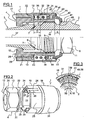
- the locking device 1 is adaptable to a pipe coupling comprising a male end 2 -or nipple-, integral with one of the pipes to be connected, and a female end 3, secured to the other of pipes to be connected, as well as a nut 4.
- the ends 2 and 3 comprise at their free end a male, ovoid-shaped sealing conformation 6 and respectively a female frustoconical conformation 7, designed to bear tightly against each other.
- the nipple 2 comprises a male thread 8 and then a collar 9 bearing on its periphery a conformation of such that a conformation 11 is distant or disjoint from the thread 8 of the element 2 in the sense that this conformation 11 that will be used for the locking is not constituted by an alteration of the thread such as a flat or a groove removing part of the threads.
- the nut 4 has at its rear end, opposite to the tip 2, an inner collar 12 and an outer conformation of turning engagement 13 such as a six-sided conformation.
- the inner collar 12 engages behind a shoulder 14 of the tip 3.
- the shoulder 14 is turned away from the tip 2 to hold the nut 4 prisoner and to receive from the nut 4 a force urging the sealing conformation 7 to seal against the sealing conformation 6 of the nozzle 2.
- the nut 4 is extended forward by a tube 32 which comprises from its front end facing the end piece 2 a female thread 16 capable of cooperating with the thread 8 of the end piece 2 to produce the clamping force supra.
- the locking device 1 comprises a support body 18 - or cup - having at its rear end a sleeve 19 which is fitted around the six-sided conformation 13 of the nut 4.
- the sleeve 19 comprises an inner surface 21 of prismatic shape with hexagonal contour which allows the sleeve 19 to be fitted substantially without play on the six-sided conformation 13 (see also figure 2 ).
- the nut 4 and the body 18 are integral in rotation.
- the sleeve 19 is equipped with retaining means for axially securing the sleeve 19 and thus the body 18 with the nut 4.
- the retaining means further comprise, in the version shown at the top of the Figures 1 and 2 , latching lugs 24 cut in the wall of the sleeve 19 by substantially axial slots 26 opening in the rear edge of the sleeve 19.
- the latching lugs 24 are terminated by latching lugs 27 which engage when the assembly is performed on the rear face 28 of the nut 4, adjacent to the rear annular edge of the six-sided conformation 13.
- the retaining means comprise crimping tongues 29 which are initially in the extension of at least some of the faces of the inner surface 21 of the sleeve 19 ( figure 2 ). Once the assembly is completed, the tabs 29 are plastically folded against the rear surface 28 of the nut 4, as shown at the bottom of FIG. figure 1 .
- the sleeve 19 has on its outer surface its own six-sided conformation 25 intended to replace the six-sided conformation 13 of the nut to allow the rotating nut to be operated using a tool such as a key (not shown) when the device 1 is in place.
- the sleeve 19 is connected rigidly and in one piece to the rear end of a skirt 31 of generally cylindrical shape which extends around the tube 32 forming an annular chamber 34 between the skirt 31 and the tube 32.
- a helical compression spring 36 having the same axis 37 as the pipe, a stop member 38 of annular shape around the axis 37 and having pads 39 mounted sliding in axial grooves 41 of the inner wall of the skirt 31, and finally a coupling member 42 having on its outer periphery a boss 43 which prevents the coupling member 42 from disengaging itself from the skirt 31 while abutting against a flange terminal 44 of the skirt 31, formed by plastic deformation, protruding radially towards the axis 37.
- the coupling member 42 protrudes outside the skirt 31 beyond the end flange 44 and has in its front part, which protrudes from the skirt 31 at least when the spring 36 is in the relatively uncompressed state, a female hexagonal recess 46 of a caliber corresponding to that of the male six-sided conformation 11 of the first element 2.
- the axial width of this impression is much smaller than that of the six-sided conformation 11 and is delimited at its rear end by abutments 47 intended to bear against a shoulder 48 adjacent to the six-sided conformation. This support limits the axial grip of the impression 46 on the conformation 11.
- the axial dimensioning of the assembly is such that when the two endpieces 2, 3 are in new condition ( figure 1 ) are pressed axially tight against each other by the tightening exerted by the nut 4, the coupling member 42 is engaged with the six-sided conformation 11, the stops 47 are pressed against the shoulder 48 while the abutment 43 is almost pressed against the flange 44.
- the pipe fittings of the generic type targeted by the invention tend to wear by radial contraction of the male part 6, and widening or widening of the frustoconical portion 7. This has the consequence of increasing the stroke of the nut 4 along the first member 2 which is necessary for the desirable axial clamping is achieved.
- This is taken into account according to the invention by a sufficient compression stroke of the spring 36, and initial axial mobility distances sufficient d ( figure 1 ) between the coupling member 42 and the free end of the nut 4, and D between the rear end of the pads 39 and the bottom of the chamber 24.
- the stop member 31 and the coupling member 42 have on their annular edges turned towards one another axially directed teeth 49, 51 and having a symmetrical profile. That is to say that with respect to a circumferential direction, the teeth, which are of triangular configuration, each have a front face and a rear face which have same oblique slope.
- the teeth 49 of the stop member 31 and the teeth 51 of the coupling member 42 have complementary profiles of so that they can interpenetrate as represented at the top of the figure 1 and to Figures 4 and 5 . On the other hand, at the bottom of figure 1 , the teeth are pointed against points.
- the device 1 is fitted onto the nut 4 from the front end of the nut 4 until the collar 22 abuts against the shoulder 23.
- the tabs 24 are urged radially outwardly to cross the shoulder 23 and then redetend elastically inwards when the beaks 27 can snap behind the face 28 of the nut 4.
- the fitting takes place without resistance until the collar 22 abuts against the shoulder 23.
- the crimping tongues 29 are folded radially. inward as depicted at the bottom of the figure 1 . It is remarkable that the device 1 forms a single unit entirely amounting to only one of the elements to lock mutually, without requiring any development on the other element.
- the nut 4 is screwed around the thread 8 of the nozzle 2 by using a wrench which is in engagement with the hexagon-shaped conformation 11 of the nozzle 2 and another wrench which is taken with the six-sided conformation 25 of the device 1.
- the stop member 42 abuts against the flange 44 under the action of the compression spring 36.
- the body coupling 42 abuts against the shoulder 48 of the nozzle 2, the spring 36 begins to compress then, as the member 42 is rotated by the interpenetration of the teeth 49 and 51, its fingerprint 46 ends up coinciding with the conformation 11 of the endpiece 2 and the spring 36 causes, while redetching itself, the interlocking of the impression 46 on the conformation 11.
- the coupling member 42 is prevented from rotating with the nut 11 and the teeth 49 and 51 click on each other with each time a brief compression of the spring 36 when the teeth 49 and 51 are found spikes against points as illustrated at the bottom of the figure 1 .
- the body d stop 38 prevented from rotating relative to the body 18 thanks to the pads 39 engaged in the grooves 41, and the coupling member 42 prevented from rotating relative to the stop member 38 due to the interpenetration of the teeth 49 and 51.
- the device could also be associated with the male end 2 and make it cooperate, for locking, with the six-sided conformation 13 of the nut. This solution is less preferred because it does not allow to disengage the elements of the connection once loosening.
- the teeth 49 and 51 have a different resistance to screwing and unscrewing, they can be made asymmetrical but they must always have a sufficiently low slope to be able to cross each other under the simple action of a couple of rotation exerted on the locking device 1 relative to the other element which is not equipped with the device.
Landscapes
- Engineering & Computer Science (AREA)
- General Engineering & Computer Science (AREA)
- Mechanical Engineering (AREA)
- Quick-Acting Or Multi-Walled Pipe Joints (AREA)
- Mutual Connection Of Rods And Tubes (AREA)
- Joints With Pressure Members (AREA)
Claims (14)
- Verriegelungsvorrichtung (1) für eine Schraubkupplung, welche ein erstes (2) und ein zweites (4) Element umfasst, welche beim Schrauben zueinander drehbar sind, wobei das erste Element (2) ein erstes Gewinde (8) und eine vom ersten Gewinde (8) entfernte Drehanschlussstelle (11) umfasst, wobei die Verriegelungsvorrichtung (1) auf dem zweiten Element (4) befestigt ist und umfasst:- ein Kupplungselement (42) für die Drehanschlussstelle (11),- ein drehfest mit einem vom zweiten Element (4) getragenen Körper (18) verbundenes Halteelement (38),- lösbare Kupplungsmittel (49, 51) zwischen dem Kupplungselement (42) und dem Halteelement (38),dadurch gekennzeichnet, dass die Kupplungsmittel (49, 51) vom Sperrklinkentyp sind, die die relative Drehung in Abschraubrichtung ermöglicht, wenn die Drehbetätigung zum Abschrauben einen vorbestimmten elastischen Widerstand überschreitet.
- Vorrichtung nach Anspruch 1, dadurch gekennzeichnet, dass die Kupplungsmittel Zähne (49, 51) umfassen, die axial ausgerichtet und auf dem Kupplungselement (42) und dem Halteelement (38) ausgebildet sind, die zueinander durch eine Feder (36) in Richtung des Ineinandergreifens der Zähne gedrückt werden.
- Vorrichtung nach Anspruch 2, dadurch gekennzeichnet, dass die zwei Elemente (38, 42) axial in Bezug zum Körper (18) beweglich sind und gemeinsam von der Feder (36) zu einem Anschlag (44) gedrückt werden, der im Körper (18) für das Kupplungselement (42) vorgesehen ist.
- Vorrichtung nach Anspruch 1 oder 2, dadurch gekennzeichnet, dass das Kupplungselement (42) gegen eine Feder (36) einziehbar ist und einen Anschlag (47) zur Abstützung auf einem Absatz (48) des ersten Elements (2) umfasst, um das axiale Eingreifen des Kupplungselements (42) auf der Drehanschlussstelle (11) zu begrenzen.
- Vorrichtung nach einem der Ansprüche 1 bis 4, dadurch gekennzeichnet, dass der Körper (18) in Manschettenform ausgebildet ist und das Halteelement (38) und teilweise das Kupplungselement (42) einschließt.
- Vorrichtung nach einem der Ansprüche 1 bis 5, dadurch gekennzeichnet, dass das Halteelement (38) und das Kupplungselement (42) um ein Rohr (32) des zweiten Elements (4) montiert sind, das innen ein Gewinde (16) zum Verschrauben mit dem ersten Element (2) aufweist.
- Vorrichtung nach einem der Ansprüche 1 bis 6, dadurch gekennzeichnet, dass der Körper (18) auf eine zweite, mit dem zweiten Element (4) verbundene Drehanschlussstelle (13) aufsteckbar ist und seine eigene Drehanschlussstelle (25) aufweist, die an Stelle der zweiten Drehanschlussstelle (13) verwendet werden kann, um die relative Drehung der beiden Elemente (2, 4) mit Hilfe von Werkzeugen auszuführen.
- Vorrichtung nach einem der Ansprüche 1 bis 7, dadurch gekennzeichnet, dass der Körper (18) auf dem zweiten Element (4) durch Einrasten (24, 27) befestigt ist.
- Vorrichtung nach einem der Ansprüche 1 bis 7, dadurch gekennzeichnet, dass der Körper (18) auf dem zweiten Element (4) durch Falzen (29) befestigt ist.
- Vorrichtung nach einem der Ansprüche 1 bis 7, dadurch gekennzeichnet, dass der Körper (18) einstückig mit dem zweiten Element (4) hergestellt ist.
- Vorrichtung nach einem der Ansprüche 1 bis 10, dadurch gekennzeichnet, dass sie als eine Einheit ausgebildet ist.
- Vorrichtung nach einem der Ansprüche 1 bis 11, dadurch gekennzeichnet, dass sie zur Gänze auf dem zweiten Element (4) montiert wird.
- Leitungsanschlussvorrichtung, umfassend einen Leitungsansatz, der mit einem männlichen Gewinde versehen ist, und eine Mutter, die auf das männliche Gewinde geschraubt werden kann und drehbar auf einem weiteren Leitungsansatz montiert ist, dadurch gekennzeichnet, dass sie ferner eine Verriegelungsvorrichtung nach einem der Ansprüche 1 bis 12 umfasst, um selektiv die relative Drehung der beiden von der Mutter und dem mit dem männlichen Gewinde versehenen Ansatz gebildeten Elemente zu verriegeln.
- Anschlussstück nach Anspruch 13, dadurch gekennzeichnet, dass das erste Element (2) und der weitere Leitungsansatz (3) unveränderte Standardelemente sind.
Applications Claiming Priority (2)
| Application Number | Priority Date | Filing Date | Title |
|---|---|---|---|
| FR0307939A FR2857080B1 (fr) | 2003-07-01 | 2003-07-01 | Dispositif de verrouillage et raccord de canalisation ainsi equipe |
| PCT/FR2004/001497 WO2005015071A1 (fr) | 2003-07-01 | 2004-06-17 | Dispositif de verrouillage et raccord de canalisation ainsi equipe |
Publications (2)
| Publication Number | Publication Date |
|---|---|
| EP1651899A1 EP1651899A1 (de) | 2006-05-03 |
| EP1651899B1 true EP1651899B1 (de) | 2010-05-19 |
Family
ID=33522637
Family Applications (1)
| Application Number | Title | Priority Date | Filing Date |
|---|---|---|---|
| EP04767359A Active EP1651899B1 (de) | 2003-07-01 | 2004-06-17 | Verriegelungsvorrichtung und damit versehenes leitungsanschlussstück |
Country Status (8)
| Country | Link |
|---|---|
| US (1) | US7883117B2 (de) |
| EP (1) | EP1651899B1 (de) |
| JP (1) | JP4571130B2 (de) |
| CN (1) | CN1820161B (de) |
| CA (1) | CA2529763C (de) |
| DE (1) | DE602004027259D1 (de) |
| FR (1) | FR2857080B1 (de) |
| WO (1) | WO2005015071A1 (de) |
Families Citing this family (22)
| Publication number | Priority date | Publication date | Assignee | Title |
|---|---|---|---|---|
| FR2873781B1 (fr) * | 2004-07-27 | 2008-05-16 | Senior Aerospace Ermeto | Dispositif de freinage autobloquant pour raccordement de canalisation |
| EP1787047A4 (de) * | 2004-09-10 | 2008-11-26 | Sps Technologies | Flüssigkeitskupplungsanordnung mit eingebautem retentionsmechanismus |
| JP4589955B2 (ja) | 2007-12-19 | 2010-12-01 | 積水化学工業株式会社 | 管状接続部材と継手部材との接続構造 |
| US10145406B2 (en) | 2009-11-05 | 2018-12-04 | Jpb Système | Self-locking screwing attachment devices and assemblies provided with same |
| US10288109B2 (en) * | 2009-11-05 | 2019-05-14 | Jpb Système | Self-locking screwing attachment device and assembly provided with same |
| FR2952149B1 (fr) * | 2009-11-05 | 2012-02-03 | Jpb Systeme | Dispositif de fixation vissant auto-verrouillable et assemblage ainsi equipe. |
| FR2973003B1 (fr) * | 2011-03-21 | 2013-03-29 | Jpb Systeme | Dispositif d'obturation a verrouillage auto-activable |
| US10436239B2 (en) | 2011-03-21 | 2019-10-08 | Jpb Système | Self-locking sealing device |
| JP5358606B2 (ja) * | 2011-03-28 | 2013-12-04 | ヒロセ電機株式会社 | ロック機構付きコネクタ |
| WO2013043367A1 (en) * | 2011-09-20 | 2013-03-28 | Micro-Coax, Inc. | Locking connector |
| US9534735B2 (en) | 2011-11-23 | 2017-01-03 | Husky Corporation | Pressure-locking nozzle for dispensing gaseous fluid |
| US8641099B2 (en) * | 2012-07-05 | 2014-02-04 | United Technologies Corporation | Coupling with one-piece plural nipples |
| GB201317952D0 (en) * | 2013-10-10 | 2013-11-27 | Guest John Int Ltd | A connector for connecting to a tube |
| US9587777B1 (en) * | 2014-07-18 | 2017-03-07 | Continental NH3 Products Co., Inc. | Nurse tank coupling with locking collar |
| GB2529890A (en) | 2014-09-08 | 2016-03-09 | Airbus Operations Ltd | Locking device |
| US9781886B1 (en) * | 2014-12-19 | 2017-10-10 | Orbit Irrigation Products, Inc. | Hand-securable sprinkler fitting |
| WO2017034715A1 (en) * | 2015-08-21 | 2017-03-02 | Eaton Corporation | Fluid coupling and method of assembly |
| WO2017106702A1 (en) * | 2015-12-18 | 2017-06-22 | Nelco Energy Services Llc | Non-preloaded threaded pipe connection for temporary high pressure piping |
| KR101808705B1 (ko) * | 2016-05-16 | 2017-12-15 | 주식회사유한훌로텍 | 합성수지관 이음부의 누출 방지구조 |
| JP6163632B1 (ja) * | 2016-06-16 | 2017-07-19 | 千住スプリンクラー株式会社 | 消火設備配管の接続構造 |
| IT201700100297A1 (it) * | 2017-09-07 | 2019-03-07 | Ali Group Srl Carpigiani | Kit di connessione ed unita’ di alimentazione prodotti comprendente detto kit. |
| US11512798B2 (en) * | 2018-11-05 | 2022-11-29 | Swagelok Company | Mechanically locking end screw arrangements |
Family Cites Families (10)
| Publication number | Priority date | Publication date | Assignee | Title |
|---|---|---|---|---|
| US1069146A (en) * | 1913-03-15 | 1913-08-05 | William H Kennedy | Coupling. |
| US1580694A (en) * | 1925-03-12 | 1926-04-13 | Harvey K Russell | Pipe coupling |
| US1691599A (en) * | 1926-10-02 | 1928-11-13 | Ingersoll Rand Co | Locking device |
| US3077330A (en) * | 1961-09-18 | 1963-02-12 | On Mark Couplings Inc | Fluid conduit coupling |
| US3201149A (en) * | 1961-12-01 | 1965-08-17 | Parker Hannifin Corp | Tube coupling |
| US5362110A (en) * | 1991-02-25 | 1994-11-08 | Moeller Manufacturing Co., Inc. | Fluid coupling and fastener capture device |
| US5188398A (en) * | 1992-01-02 | 1993-02-23 | General Electric Company | Redundantly locked fluid coupling |
| FR2710715B1 (fr) | 1993-09-29 | 1996-09-20 | Marc Jean Pierre | Verrou auto-bloquant pour canalisations. |
| US5348349A (en) * | 1993-11-22 | 1994-09-20 | Sloane Norman S | Splined safety lock |
| US5871239A (en) * | 1996-10-31 | 1999-02-16 | Stanley Aviation Corporation | Positive lock coupling |
-
2003
- 2003-07-01 FR FR0307939A patent/FR2857080B1/fr not_active Expired - Lifetime
-
2004
- 2004-06-17 WO PCT/FR2004/001497 patent/WO2005015071A1/fr active Application Filing
- 2004-06-17 US US10/562,682 patent/US7883117B2/en active Active
- 2004-06-17 DE DE602004027259T patent/DE602004027259D1/de active Active
- 2004-06-17 JP JP2006518254A patent/JP4571130B2/ja active Active
- 2004-06-17 CN CN200480018649.0A patent/CN1820161B/zh active Active
- 2004-06-17 EP EP04767359A patent/EP1651899B1/de active Active
- 2004-06-17 CA CA2529763A patent/CA2529763C/fr active Active
Also Published As
| Publication number | Publication date |
|---|---|
| DE602004027259D1 (de) | 2010-07-01 |
| CN1820161B (zh) | 2012-12-12 |
| CN1820161A (zh) | 2006-08-16 |
| CA2529763A1 (fr) | 2005-02-17 |
| EP1651899A1 (de) | 2006-05-03 |
| JP2007514895A (ja) | 2007-06-07 |
| FR2857080A1 (fr) | 2005-01-07 |
| FR2857080B1 (fr) | 2007-04-13 |
| CA2529763C (fr) | 2012-08-28 |
| US7883117B2 (en) | 2011-02-08 |
| JP4571130B2 (ja) | 2010-10-27 |
| US20060151994A1 (en) | 2006-07-13 |
| WO2005015071A1 (fr) | 2005-02-17 |
Similar Documents
| Publication | Publication Date | Title |
|---|---|---|
| EP1651899B1 (de) | Verriegelungsvorrichtung und damit versehenes leitungsanschlussstück | |
| EP2689110B1 (de) | Absperrvorrichtung mit automatisch aktivierbarer verriegelung | |
| EP0791141B1 (de) | Selbstverriegelbare verschlussvorrichtung | |
| EP0727025B1 (de) | Selbstsichernder riegel für rohrleitungen | |
| CA2082301C (fr) | Joint verrouille pour canalisations | |
| EP2908042B1 (de) | Bajonettverbindung zur lösbaren Verbindung von Kanalisationsrohren | |
| EP2592500B1 (de) | Armbanduhrengehäuse, das ein Kronrad mit Ausrichtungsgedächtnis umfasst | |
| WO2003048624A1 (fr) | Systeme de serrage pour le raccordement etanche de deux tubes ayant des surfaces d'appui. | |
| EP2496849B1 (de) | Selbstblockierende schraubfixiervorrichtung und anordnung damit | |
| FR2726620A1 (fr) | Procede de montage d'un embrayage de verrouillage pour accouplement hydrocinetique, notamment pour vehicule automobile, embrayage de verrouillage et accouplement hydrocinetique le comportant | |
| EP1853977B1 (de) | Blockierbarer drücker | |
| FR2836202A1 (fr) | Raccord destine a relier des conduites hydrauliques | |
| EP0102898B1 (de) | Mutter mit automatischer positiver Sicherung | |
| EP1702694A1 (de) | Werkzeugspannfutter für drehende Maschine, mit Verriegelungsmittel | |
| EP0402198A1 (de) | Verriegelungsmutter | |
| EP0272967B1 (de) | Kupplungsausrücklager mit bistabiler Federscheibe, insbesondere für Kraftfahrzeuge | |
| FR2547002A1 (fr) | Butee de debrayage et outil de montage pour celle-ci | |
| FR2626330A1 (fr) | Ecrou de fixation | |
| WO1994002770A1 (fr) | Joint verrouille a emboitement entre elements tubulaires | |
| FR2482251A1 (fr) | Dispositif de raccordement d'un ecrou tournant a l'extremite d'un tuyau du type onduleux | |
| FR2954428A1 (fr) | Dispositif limiteur de couple et bouchon pour tete de tubulure comportant un tel dispositif | |
| FR3002993A1 (fr) | Organe d'assemblage vissable | |
| EP0953778A1 (de) | Schnellmontagemutter bestehend aus zwei Mutterhälften, und Befestigungsvorrichtung insbesondere für Betonschalung mit Verwendung dieser Mutter | |
| FR2805482A1 (fr) | Piece mecanique de transmission | |
| WO2001031209A1 (fr) | Dispositif ecrou de mise en place rapide, a deux demi-ecrous, et agencement de blocage notamment pour coffrage de beton, utilisant un tel dispositif ecrou |
Legal Events
| Date | Code | Title | Description |
|---|---|---|---|
| PUAI | Public reference made under article 153(3) epc to a published international application that has entered the european phase |
Free format text: ORIGINAL CODE: 0009012 |
|
| 17P | Request for examination filed |
Effective date: 20060130 |
|
| AK | Designated contracting states |
Kind code of ref document: A1 Designated state(s): DE FR GB |
|
| DAX | Request for extension of the european patent (deleted) | ||
| RBV | Designated contracting states (corrected) |
Designated state(s): DE FR GB |
|
| GRAP | Despatch of communication of intention to grant a patent |
Free format text: ORIGINAL CODE: EPIDOSNIGR1 |
|
| GRAS | Grant fee paid |
Free format text: ORIGINAL CODE: EPIDOSNIGR3 |
|
| GRAA | (expected) grant |
Free format text: ORIGINAL CODE: 0009210 |
|
| AK | Designated contracting states |
Kind code of ref document: B1 Designated state(s): DE FR GB |
|
| REG | Reference to a national code |
Ref country code: GB Ref legal event code: FG4D Free format text: NOT ENGLISH |
|
| REF | Corresponds to: |
Ref document number: 602004027259 Country of ref document: DE Date of ref document: 20100701 Kind code of ref document: P |
|
| PLBE | No opposition filed within time limit |
Free format text: ORIGINAL CODE: 0009261 |
|
| STAA | Information on the status of an ep patent application or granted ep patent |
Free format text: STATUS: NO OPPOSITION FILED WITHIN TIME LIMIT |
|
| 26N | No opposition filed |
Effective date: 20110222 |
|
| REG | Reference to a national code |
Ref country code: DE Ref legal event code: R097 Ref document number: 602004027259 Country of ref document: DE Effective date: 20110221 |
|
| REG | Reference to a national code |
Ref country code: FR Ref legal event code: PLFP Year of fee payment: 13 |
|
| REG | Reference to a national code |
Ref country code: FR Ref legal event code: PLFP Year of fee payment: 14 |
|
| REG | Reference to a national code |
Ref country code: DE Ref legal event code: R082 Ref document number: 602004027259 Country of ref document: DE Representative=s name: SCHOEN, THILO, DIPL.-PHYS., DE |
|
| REG | Reference to a national code |
Ref country code: FR Ref legal event code: PLFP Year of fee payment: 15 |
|
| PGFP | Annual fee paid to national office [announced via postgrant information from national office to epo] |
Ref country code: GB Payment date: 20220622 Year of fee payment: 19 |
|
| PGFP | Annual fee paid to national office [announced via postgrant information from national office to epo] |
Ref country code: FR Payment date: 20220627 Year of fee payment: 19 |
|
| PGFP | Annual fee paid to national office [announced via postgrant information from national office to epo] |
Ref country code: DE Payment date: 20220620 Year of fee payment: 19 |
|
| REG | Reference to a national code |
Ref country code: DE Ref legal event code: R119 Ref document number: 602004027259 Country of ref document: DE |
|
| GBPC | Gb: european patent ceased through non-payment of renewal fee |
Effective date: 20230617 |
|
| PG25 | Lapsed in a contracting state [announced via postgrant information from national office to epo] |
Ref country code: DE Free format text: LAPSE BECAUSE OF NON-PAYMENT OF DUE FEES Effective date: 20240103 Ref country code: GB Free format text: LAPSE BECAUSE OF NON-PAYMENT OF DUE FEES Effective date: 20230617 |