US1069146A - Coupling. - Google Patents
Coupling. Download PDFInfo
- Publication number
- US1069146A US1069146A US75454013A US1913754540A US1069146A US 1069146 A US1069146 A US 1069146A US 75454013 A US75454013 A US 75454013A US 1913754540 A US1913754540 A US 1913754540A US 1069146 A US1069146 A US 1069146A
- Authority
- US
- United States
- Prior art keywords
- lugs
- ring
- male
- coupling
- hose
- Prior art date
- Legal status (The legal status is an assumption and is not a legal conclusion. Google has not performed a legal analysis and makes no representation as to the accuracy of the status listed.)
- Expired - Lifetime
Links
- 230000008878 coupling Effects 0.000 title description 16
- 238000010168 coupling process Methods 0.000 title description 16
- 238000005859 coupling reaction Methods 0.000 title description 16
- 241000606643 Anaplasma centrale Species 0.000 description 1
- 238000006730 Kennedy cyclization reaction Methods 0.000 description 1
- 238000006073 displacement reaction Methods 0.000 description 1
- 230000002452 interceptive effect Effects 0.000 description 1
- 238000012856 packing Methods 0.000 description 1
- 230000001105 regulatory effect Effects 0.000 description 1
- 230000000717 retained effect Effects 0.000 description 1
Images

Classifications
-
- F—MECHANICAL ENGINEERING; LIGHTING; HEATING; WEAPONS; BLASTING
- F16—ENGINEERING ELEMENTS AND UNITS; GENERAL MEASURES FOR PRODUCING AND MAINTAINING EFFECTIVE FUNCTIONING OF MACHINES OR INSTALLATIONS; THERMAL INSULATION IN GENERAL
- F16L—PIPES; JOINTS OR FITTINGS FOR PIPES; SUPPORTS FOR PIPES, CABLES OR PROTECTIVE TUBING; MEANS FOR THERMAL INSULATION IN GENERAL
- F16L37/00—Couplings of the quick-acting type
- F16L37/24—Couplings of the quick-acting type in which the connection is made by inserting one member axially into the other and rotating it to a limited extent, e.g. with bayonet-action
- F16L37/244—Couplings of the quick-acting type in which the connection is made by inserting one member axially into the other and rotating it to a limited extent, e.g. with bayonet-action the coupling being co-axial with the pipe
- F16L37/252—Couplings of the quick-acting type in which the connection is made by inserting one member axially into the other and rotating it to a limited extent, e.g. with bayonet-action the coupling being co-axial with the pipe the male part having lugs on its periphery penetrating into the corresponding slots provided in the female part
-
- Y—GENERAL TAGGING OF NEW TECHNOLOGICAL DEVELOPMENTS; GENERAL TAGGING OF CROSS-SECTIONAL TECHNOLOGIES SPANNING OVER SEVERAL SECTIONS OF THE IPC; TECHNICAL SUBJECTS COVERED BY FORMER USPC CROSS-REFERENCE ART COLLECTIONS [XRACs] AND DIGESTS
- Y10—TECHNICAL SUBJECTS COVERED BY FORMER USPC
- Y10T—TECHNICAL SUBJECTS COVERED BY FORMER US CLASSIFICATION
- Y10T403/00—Joints and connections
- Y10T403/70—Interfitted members
- Y10T403/7005—Lugged member, rotary engagement
- Y10T403/7007—Bayonet joint
Definitions
- My invention' relates to couplings Well adapted, among other uses, for hose, and has for its essential objects the combination in a single structure of a swiveling and an interlocking action whereby any kinks or torsion of the attached hose will not 1nterfere with the efficiency of the operation the appended claims.
- My coupling comprises in detail a tubuf lar male member A comprisinga reduced end or shank portion a, an exteriorly intermediate portion a, and an inner end .portion a2 provided 1n the present instance with external threads 'as engaging the interior threads b of aring B provided with an inwardly directed flange b interspaced from the end face of the portion a2.
- the ring B constit'utes for all practical purposes a part of the member A.
- An annular packing ring C may if desired be seated in an internalA annular cavity c in the member A.
- A'l tubular male member D has intermediateits length two or more annularly disposed radial lugs dwith'resultant spacesd, and upon itis outer endexternal threads d2.
- the spaces e are of such dimensions as to allow the lugs d to pass intermediate the lugs e as a sliding fit, and a par-.
- Loose upon the member D- is a locking tube or ring F vof a large internal bore throughouta-portion of its length forming a ⁇ recess f and having the exterior of its innerV end f reduced to form an annular shoulder f? adapted to bear against the portion b of the member B.
- Integral with the portion f arevsquare projections f3 forming resultant spaces f4.
- the projections f3 are of such dimensions as to slide throughvthe spaces d and e', and thus eng-age the lugs d and e so that the lugs can not rotate relatively to each other, thus preventing de-v tachment of the members A and D.
- the member F however is when engaged rotatable relatively to the member A, but is held against escape longitudinally by a nut Gr,
- This nut. is provided with a hexed exterior portion g adapted to accommodate a wrench and has near its inner end internal threads g adapted to engage the threads d2 upon the member D. It is also provided near its outer end with internal threads g2 adapted to engage threads h upon the end of a hose or pipe H.
- the nutG is ofy suiiiciently reduced diameter at its forward portion, as at g3., to permit the entrance within the cavity f of the member F, pressed against one end of a helical spring I which surrounds the member D within the cavity, and has its opposite end pressing against the member F at the base of the bore or cavity as at z'. It will be observed that the pressure of the spring which abuts against the inner end of the member G acting against the shoulder i yieldingly forces the projections f3 of the member F into their seats intermediate the lugs al and e.'
- the female member A or A, B carries permanently the rotary ring E.
- the male coupling member D is inserted within the member A, the lugs d passing through the spaces e', and then passing, by a turn of the member D, behind and in longitudinal alinement with the lugs e, leaving the spaces d, e in valinement.
- the lugs f3 are inserted by the forward impulsion of the member F under the pressure of the spring I, whose pressure is regulated by the nut Gr.
- hose may be forced upon the shank, the bosses K passing throughV the slits, and seating themselves in the openings m.
- the end of the hose is clamped tightly upon the shank portion a by means of curved or .semicircular nuts or plates N which rest'upon the'exterior ofthe hose and conform with the shape thereof, and are each provided with a. central opening n to permit passage therethrough of the bosses K.
- the portions ofthe plates Naround the openings n are preferably flattened as at n2 to form seats for the nuts L, by which nutsthe plates are clamped upon the hose.r
- ribs may be larranged in any preferred manner. In the present instance they comprise amarginal rectangular rib or ribs o, a c entral annular rib 0, and radial ribs 02. These ribs form four depressions 03 adapted to receive the material of the hose M as the plates N are compressed thereon.
- screws L may be employed as shown in Figs. 12 and 13.
- the screws comprise rounded head portions Z and threaded Shanks Z2 adapted to engage screw threads lo formed in tubular bosses K What I claim is l.
- a coupling the combinatiomwith a female member, of an axially movable ring mounted in said member provided with lugs, avmale member loose in the ring provided with lugs engaging the lugs upon the ring, and a locking sleeve loose upon the male member provided with projections engaging the lugs upon both the ring and the male member, and means for causing engagement yof said projections and lugs, and preventing displacement ofthe said members and allowinlg joint rotary movement of said lugs.
- a coupling the combination of a female member, of a ring rotatably mounted in said member, inwardly directed lugs upon the ring, a male member extending into the ring, exterior lugs upon the male Amember adapted to engage the lugs upon the ring, a locking sleeve loose upon the male member, projections'upon the sleeve adapted to engage the lugs upon both-the ring and the male member, and resilient means uponthe male member engaging the sleeve for forcing the projections into engagement with the lugs.
Landscapes
- Engineering & Computer Science (AREA)
- General Engineering & Computer Science (AREA)
- Mechanical Engineering (AREA)
- Quick-Acting Or Multi-Walled Pipe Joints (AREA)
Description
W. H. KENNEDY.
GOUPLING.
APPLICATION FILED MAR. 15, 1913.
Patented Aug. 5, 1913.
2 SHEETS-SHEET 1.
' 1' 7 Z/-l fr /15 fzveniw@ AVI' [Il Wz'inese. m5@
W. H. KENNEDY.
COUPLING. APPLICATION FILED MAR.15, 1913.
Patented Aug. 5, 1.913.v
2 SHEETS-SHEET 2.
i UNITED STATES PATENT oE-EioE.
WILLIAM H. KENNEDY, 0F (IFIICAGr,v ILLINOIS.
COU'PLING.
Specication of Letters Patent.
` Patented Aug.5,1e13.
Application led March 15, 1913. Serial No. 754,540.
To aZZ 'whom it may concern s A Be it known that I, WILLIAM H. KEN- NEDY, a citizen of the United States, residing at Chicago, in the county of Cook and State of Illinois, have invented certain new and useful Improvements in Couplings, of which the following is a specification.
-. My invention' relates to couplings Well adapted, among other uses, for hose, and has for its essential objects the combination in a single structure of a swiveling and an interlocking action whereby any kinks or torsion of the attached hose will not 1nterfere with the efficiency of the operation the appended claims.
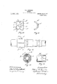
In the accompanying drawings which form a part of this specication:-Figure 1 is a side elevation of' my hose coupling, Fig. 2,
- Va longitudinal central section of the same,
showing parts broken away and partially in side elevation, Fig. 3,'a section on line fr m of Fig. 1, Figs. 4 and 5, end andsside elevations respectively of one coupling member, Fig. 6, alongitudinal section of the operating end of one coupling member disengaged from its combination member, Fig. 7, an end elevation of the same, "Figs, 8 and 9, end and side elevations respectively' of the locking sleeve, Figs. 10 and 11, rear and side elevations respectively of one of the clampin plates, Fig. l2, a side elevation of a modi ed form of my clamping device, Fig. `13, a section of the vsame on line y y of Fig. 12, and Fig. 14, a plan of the end portion of a hose before engagement.
My coupling comprises in detail a tubuf lar male member A comprisinga reduced end or shank portion a, an exteriorly intermediate portion a, and an inner end .portion a2 provided 1n the present instance with external threads 'as engaging the interior threads b of aring B provided with an inwardly directed flange b interspaced from the end face of the portion a2. When the parts are finally assembled the ring B constit'utes for all practical purposes a part of the member A. An annular packing ring C may if desired be seated in an internalA annular cavity c in the member A.
A'l tubular male member D has intermediateits length two or more annularly disposed radial lugs dwith'resultant spacesd, and upon itis outer endexternal threads d2. Rotatable exteriorly of the member D in contact with the member B and retained by the Harige b', vis a ring E having an internal diameter suiicient 'to receive the lugs d, and provided with inwardly directed ra-v dially disposed lugs e with intervening spaces e. The spaces e are of such dimensions as to allow the lugs d to pass intermediate the lugs e as a sliding fit, and a par-.
tial turn bf the member D Serves to bring the lugs d into a longitudinal alinement with the lugs e at their rear, and the spaces d are at the same. time brought into longitudinal alinement with the spaces e.
Loose upon the member D- isa locking tube or ring F vof a large internal bore throughouta-portion of its length forming a` recess f and having the exterior of its innerV end f reduced to form an annular shoulder f? adapted to bear against the portion b of the member B. Integral with the portion f arevsquare projections f3 forming resultant spaces f4. The projections f3 are of such dimensions as to slide throughvthe spaces d and e', and thus eng-age the lugs d and e so that the lugs can not rotate relatively to each other, thus preventing de-v tachment of the members A and D. The member F however is when engaged rotatable relatively to the member A, but is held against escape longitudinally by a nut Gr, This nut. is provided with a hexed exterior portion g adapted to accommodate a wrench and has near its inner end internal threads g adapted to engage the threads d2 upon the member D. It is also provided near its outer end with internal threads g2 adapted to engage threads h upon the end of a hose or pipe H. The nutG is ofy suiiiciently reduced diameter at its forward portion, as at g3., to permit the entrance within the cavity f of the member F, pressed against one end of a helical spring I which surrounds the member D within the cavity, and has its opposite end pressing against the member F at the base of the bore or cavity as at z'. It will be observed that the pressure of the spring which abuts against the inner end of the member G acting against the shoulder i yieldingly forces the projections f3 of the member F into their seats intermediate the lugs al and e.'
The assembling of the coupling has been already somewhat described. The female member A or A, B, carries permanently the rotary ring E. The male coupling member D is inserted within the member A, the lugs d passing through the spaces e', and then passing, by a turn of the member D, behind and in longitudinal alinement with the lugs e, leaving the spaces d, e in valinement. Into these spaces the lugs f3 are inserted by the forward impulsion of the member F under the pressure of the spring I, whose pressure is regulated by the nut Gr. In the described position the coupling is locked against accidental disengagement, while not interfering with the swiveling of the parts E, D, F, and Gr relatively to the member A vor A, B.' To disconnect the coupling thus engaged Ythe member F is manually pulled rearwardly aga' t the tension of the spring I until the projections f3y have been withdrawn from the opening d', e', and. then slightly turned so. that the ends of the pro- -jections f3 are opposite the faces of the lugs .6, and then by' a turning of the member A relatively to the member G, the lugs d of the member D arey turned suiiiciently to pass through the openin s cape of the memberflr) from engagement.
Cast upon the shank portion a of the coupling member A, at an intermediate portion thereof, arel diametrically oppositely dis' posed bosses or projecti ns K rovided with threaded end portions adapted `to receive nuts L. The hose M is applied to the shank.
portion a and is `longitudinally slit at dia- `metrically opposite points at itsI forward end as at m, and at the end of thel slits is provided with-circular openings m. .By means of the slit portions the hose may be forced upon the shank, the bosses K passing throughV the slits, and seating themselves in the openings m. The end of the hose is clamped tightly upon the shank portion a by means of curved or .semicircular nuts or plates N which rest'upon the'exterior ofthe hose and conform with the shape thereof, and are each provided with a. central opening n to permit passage therethrough of the bosses K. The portions ofthe plates Naround the openings n are preferably flattened as at n2 to form seats for the nuts L, by which nutsthe plates are clamped upon the hose.r In order to increase the engaging power of the nlates N, they are provided upon their inner e and permit the es? maarre faces with ribs, as shown in Figs. 10 and 11. These ribs may be larranged in any preferred manner. In the present instance they comprise amarginal rectangular rib or ribs o, a c entral annular rib 0, and radial ribs 02. These ribs form four depressions 03 adapted to receive the material of the hose M as the plates N are compressed thereon.
In place of the nuts L screws L may be employed as shown in Figs. 12 and 13. The screws comprise rounded head portions Z and threaded Shanks Z2 adapted to engage screw threads lo formed in tubular bosses K What I claim is l. In a coupling, the combinatiomwith a female member, of an axially movable ring mounted in said member provided with lugs, avmale member loose in the ring provided with lugs engaging the lugs upon the ring, anda locking sleeve loose upon the male member provided with projections engaging the lugs upon both the ring and the male member, and means for causing engagement yof said projections and lugs, and preventing displacement ofthe said members and allowinlg joint rotary movement of said lugs.
l 2., n a coupling, the combination of a female member, of a ring rotatably mounted in said member, inwardly directed lugs upon the ring, a male member extending into the ring, exterior lugs upon the male Amember adapted to engage the lugs upon the ring, a locking sleeve loose upon the male member, projections'upon the sleeve adapted to engage the lugs upon both-the ring and the male member, and resilient means uponthe male member engaging the sleeve for forcing the projections into engagement with the lugs.
3. In a coupling, the combination with a female member, of an axially movable ring mounted in said member, lugs upon the ring, a male member loose in the ring, lugs upon the male member engaging the lugs upon the ring, a lockingsleeve loose upon the male member provided with prpjections adapted to` engage the lugsxupon both. the ring and the male member, and provided with an nternal cavity, a spring updn the male member within said cavity, and a nut upon theV pressing against one end of male member the spring.
4f. In a coupling, the combination with a female member, of an independent ring rotatably mounted in said member, inwardly' directed lugs upon the ring forming a series of openings, a male, member loose in the ring, radial lugs upon -the exterior of the male member forming a series of openings, the lugs upon the male member'being adapted to pass through the openings in the ring,
and a locking sleeve slidably mounted upon the male member provided with a cavity,
av spring upon ,the male member within' the cavity having one end pressing against its endl olposite to the end engaging the the ring at one end of a cavity, said male male mem er.
member'being provided at its end with a In testimony whereof I have axed my screw thread, and a hollow nut provided signature in presence `of two witnesses. with threads at one end adapted to engage WILLIAM H. KENNEDY. the threads upon the male memberandabut- Witnesses: p
tingagainst one end of the spring, said nut LOUIS J. SUAREZ,
being provided with an additionalV thread at BEDA M. SATiERuzE.
Priority Applications (1)
| Application Number | Priority Date | Filing Date | Title |
|---|---|---|---|
| US75454013A US1069146A (en) | 1913-03-15 | 1913-03-15 | Coupling. |
Applications Claiming Priority (1)
| Application Number | Priority Date | Filing Date | Title |
|---|---|---|---|
| US75454013A US1069146A (en) | 1913-03-15 | 1913-03-15 | Coupling. |
Publications (1)
| Publication Number | Publication Date |
|---|---|
| US1069146A true US1069146A (en) | 1913-08-05 |
Family
ID=3137384
Family Applications (1)
| Application Number | Title | Priority Date | Filing Date |
|---|---|---|---|
| US75454013A Expired - Lifetime US1069146A (en) | 1913-03-15 | 1913-03-15 | Coupling. |
Country Status (1)
| Country | Link |
|---|---|
| US (1) | US1069146A (en) |
Cited By (10)
| Publication number | Priority date | Publication date | Assignee | Title |
|---|---|---|---|---|
| US2448548A (en) * | 1944-04-05 | 1948-09-07 | George W Purdy | Coupling |
| US2459477A (en) * | 1946-02-05 | 1949-01-18 | John Van Schuyver | Valve coupling |
| US2726570A (en) * | 1949-10-06 | 1955-12-13 | American Optical Corp | Optical diagnostic instruments |
| US2751940A (en) * | 1952-02-23 | 1956-06-26 | Leonidas C Miller | Fluid pressure power-operated reciprocating shaft tool |
| US2813538A (en) * | 1955-02-25 | 1957-11-19 | Miehle Goss Dexter Inc | Ink level control mechanism |
| US3079178A (en) * | 1959-04-13 | 1963-02-26 | Airaterra | Flush coupling assemblies |
| US4376466A (en) * | 1981-04-01 | 1983-03-15 | Takashima & Co., Ltd. | Fire extinguishing apparatus for airdropping a fire-extinguishing agent |
| US5401066A (en) * | 1989-09-25 | 1995-03-28 | Preece Incorporated | Fluid flow connector |
| US5931507A (en) * | 1997-09-15 | 1999-08-03 | The Johnson Corporation | Rotary joint with body lock system |
| US20060151994A1 (en) * | 2003-07-01 | 2006-07-13 | Jpb Systeme | Locking device and a line fitting provided therewith |
-
1913
- 1913-03-15 US US75454013A patent/US1069146A/en not_active Expired - Lifetime
Cited By (11)
| Publication number | Priority date | Publication date | Assignee | Title |
|---|---|---|---|---|
| US2448548A (en) * | 1944-04-05 | 1948-09-07 | George W Purdy | Coupling |
| US2459477A (en) * | 1946-02-05 | 1949-01-18 | John Van Schuyver | Valve coupling |
| US2726570A (en) * | 1949-10-06 | 1955-12-13 | American Optical Corp | Optical diagnostic instruments |
| US2751940A (en) * | 1952-02-23 | 1956-06-26 | Leonidas C Miller | Fluid pressure power-operated reciprocating shaft tool |
| US2813538A (en) * | 1955-02-25 | 1957-11-19 | Miehle Goss Dexter Inc | Ink level control mechanism |
| US3079178A (en) * | 1959-04-13 | 1963-02-26 | Airaterra | Flush coupling assemblies |
| US4376466A (en) * | 1981-04-01 | 1983-03-15 | Takashima & Co., Ltd. | Fire extinguishing apparatus for airdropping a fire-extinguishing agent |
| US5401066A (en) * | 1989-09-25 | 1995-03-28 | Preece Incorporated | Fluid flow connector |
| US5931507A (en) * | 1997-09-15 | 1999-08-03 | The Johnson Corporation | Rotary joint with body lock system |
| US20060151994A1 (en) * | 2003-07-01 | 2006-07-13 | Jpb Systeme | Locking device and a line fitting provided therewith |
| US7883117B2 (en) * | 2003-07-01 | 2011-02-08 | Jpb Systeme | Locking device and a line fitting provided therewith |
Similar Documents
| Publication | Publication Date | Title |
|---|---|---|
| US1193446A (en) | Hose-coupling | |
| US3534988A (en) | Tube end mounted sleeve | |
| US643358A (en) | Hose-coupling. | |
| US1261687A (en) | Hose-coupling. | |
| US1069146A (en) | Coupling. | |
| US1039354A (en) | Hose-coupling. | |
| US2449920A (en) | Conduit coupling | |
| US646590A (en) | Hose or pipe coupling. | |
| US1673338A (en) | Pipe coupling | |
| US1195433A (en) | De witt c | |
| EP0549860B1 (en) | Coupling device for two conducts, in particular for fuel conducts | |
| US1006190A (en) | Hose-coupling. | |
| US1098265A (en) | Hose-coupling. | |
| US3473782A (en) | Coupling device | |
| US1011284A (en) | Hose-coupling. | |
| US1029715A (en) | Hose-coupling. | |
| US1196928A (en) | Hose-coupling. | |
| US1039536A (en) | Hose-coupling. | |
| US617591A (en) | Hose-coupling | |
| US1143816A (en) | Compression-coupling. | |
| US487893A (en) | And charles | |
| US328427A (en) | nusbeck | |
| US360779A (en) | Hose-coupling | |
| US1187321A (en) | Hose-coupling. | |
| US1393908A (en) | Quick-acting high-pressure connection |