EP1650827A2 - Antenna mounting structure - Google Patents
Antenna mounting structure Download PDFInfo
- Publication number
- EP1650827A2 EP1650827A2 EP05022890A EP05022890A EP1650827A2 EP 1650827 A2 EP1650827 A2 EP 1650827A2 EP 05022890 A EP05022890 A EP 05022890A EP 05022890 A EP05022890 A EP 05022890A EP 1650827 A2 EP1650827 A2 EP 1650827A2
- Authority
- EP
- European Patent Office
- Prior art keywords
- protrusion
- fixation member
- slit
- bolt
- wedge
- Prior art date
- Legal status (The legal status is an assumption and is not a legal conclusion. Google has not performed a legal analysis and makes no representation as to the accuracy of the status listed.)
- Granted
Links
- 210000000078 claw Anatomy 0.000 claims description 188
- 239000002184 metal Substances 0.000 description 8
- 230000003252 repetitive effect Effects 0.000 description 4
- 239000011347 resin Substances 0.000 description 3
- 229920005989 resin Polymers 0.000 description 3
- 230000005489 elastic deformation Effects 0.000 description 2
- 239000000463 material Substances 0.000 description 2
- 230000004048 modification Effects 0.000 description 2
- 238000012986 modification Methods 0.000 description 2
- 238000009751 slip forming Methods 0.000 description 2
- 230000008054 signal transmission Effects 0.000 description 1
Images









Classifications
-
- H—ELECTRICITY
- H01—ELECTRIC ELEMENTS
- H01Q—ANTENNAS, i.e. RADIO AERIALS
- H01Q1/00—Details of, or arrangements associated with, antennas
- H01Q1/12—Supports; Mounting means
- H01Q1/1207—Supports; Mounting means for fastening a rigid aerial element
- H01Q1/1214—Supports; Mounting means for fastening a rigid aerial element through a wall
-
- H—ELECTRICITY
- H01—ELECTRIC ELEMENTS
- H01Q—ANTENNAS, i.e. RADIO AERIALS
- H01Q1/00—Details of, or arrangements associated with, antennas
- H01Q1/27—Adaptation for use in or on movable bodies
- H01Q1/32—Adaptation for use in or on road or rail vehicles
- H01Q1/325—Adaptation for use in or on road or rail vehicles characterised by the location of the antenna on the vehicle
- H01Q1/3275—Adaptation for use in or on road or rail vehicles characterised by the location of the antenna on the vehicle mounted on a horizontal surface of the vehicle, e.g. on roof, hood, trunk
-
- H—ELECTRICITY
- H01—ELECTRIC ELEMENTS
- H01Q—ANTENNAS, i.e. RADIO AERIALS
- H01Q1/00—Details of, or arrangements associated with, antennas
- H01Q1/27—Adaptation for use in or on movable bodies
- H01Q1/32—Adaptation for use in or on road or rail vehicles
- H01Q1/3208—Adaptation for use in or on road or rail vehicles characterised by the application wherein the antenna is used
- H01Q1/3216—Adaptation for use in or on road or rail vehicles characterised by the application wherein the antenna is used where the road or rail vehicle is only used as transportation means
Definitions
- the present invention relates to an antenna mounting structure in which an antenna base of a vehicle antenna is mounted on and fixed to a roof or the like of a vehicle body.
- a bolt provided in such a manner as to project downwards from an antenna base of a vehicle antenna is passed through a hole opened in the roof or the like of the vehicle body from thereabove, a claw washer is fitted on the bolt which projects into an inside of the vehicle body from the inside of the vehicle, and furthermore, a nut is screwed on the bolt so as to fix the antenna base to the roof or the like of the vehicle body.
- an internal thread is engraved on an antenna base, and a bolt on which a claw washer is passed is passed through a hole opened in the vehicle body from the inside of the vehicle so as to be screwed into the internal thread on the antenna base, whereby the antenna base is fixed to the roof or the like of the vehicle body.
- claws of the claw washer bite into an inner face of the vehicle body, so that the antenna base is fixedly mounted on the vehicle body in an electrically conductive manner.
- Figs. 25A to 27B show one example of such a mounting structure.
- a bolt 150a is provided on an antenna base 150 in such a manner as to project downwards therefrom.
- a claw washer 120 is fitted on the bolt 150a which is formed substantially into a C-shape which is partially opened as viewed from a top thereof and which has provided thereon in such a manner as to project upwards from an upper edge portion thereof claws 120b and two or more provisional fixation claws 120a which expand wider upwards so that a distance between distal ends thereof becomes larger than the upper edge portion.
- a nut 152 is screwed on a lower end portion of the bolt 150a.
- a wedge-shaped member 110 is provided on the antenna base in such a manner as to face a slit formed in the substantially C-shaped claw washer 120.
- a truncated-conical portion is provided on the nut 152 which is made to become wider at a lower end in such a manner that an upper outer diameter becomes smaller while a lower outer diameter becomes larger than a lower inner diameter of the claw washer 120.
- a cable hole through which a cable 122 is to be passed is opened in the antenna base 150 at a position which is an opposite side of the bolt 150a with respect to a position where the wedge-shaped member 110 is provided.
- a notch is provided in the claw washer 120 in such a manner as to face the cable hole so as to allow the escape of the cable 122 when the cable 122 is pulled into the inside of the vehicle body from the antenna base through a hole 124.
- the bolt 150a is inserted into the hole 124 in the vehicle body from above in such a state that the claw washer 120 is fitted on the bolt 150a on the antenna base 150 with the nut 152 fittingly screwed on the bolt 150a to a slight extent so that the bolt 150a, the claw washer 120 and the nut 152 are integrated with each other.
- the provisional fixation claws 120a of the claw washer 120 elastically deform inwards and is then allowed to pass through the hole 124, and after having passed therethrough, the provisional fixation claws 120a elastically restore to thereby expand wider than the hole 124 and restricts the upward dislodgement of the antenna base 150.
- the antenna base 150 can be provisionally fixed to the vehicle body only by the simple work of passing the bolt 150a through the hole 124 from thereabove.
- the slit in the claw washer 120 is expanded by the action of the wedge-shaped member 110 of the antenna base 150 and the truncated-conical portion of the nut 152, and this deforms largely the substantially C-shape of the claw washer 120 in diameter, so that the claws 120b are brought into abutment with the inner face of the vehicle body at circumferential edge portions of the hole 124. Furthermore, the claws 120b bite into the inner face of the vehicle body when the nut 152 is tightened strongly, whereby the antenna base 150 is fixed to the vehicle body and an electric conduction is secured.
- the position of the notch which is provided in the claw washer 120 to allow the escape of the cable 122, is caused to deviate in a direction in which the acting force attempts to rotate the claw washer 120 together with the nut 152.
- the cable 122 is damaged by the deviation of the position of the notch in the claw washer 120.
- a central position between the claws 120b situated at both the end portions of the slit expanded by the claw washer 120 is deviated in the direction in which the claw washer 120 is attempted to be rotated together with the nut 152 relative to the hole 124 and hence is not always made to face the circumferential edge portion of the hole 124 but is made to face the hole 124. Accordingly, there is a possibility that the antenna base 150 is fixed to the vehicle body in an inclined manner.
- a structure for mounting an antenna device on a first side of a panel body comprising:
- the first fixation member is rotated in accompany with the screwing action of the second fixation member.
- one end portion of the slit is restricted in position by the wedge member and hence, the slit is expanded only at the other end portion thereof. Accordingly, the cable passed through the cutout portion of the wedge member is prevented from being damaged by the screwing action.
- the second fixation member may be a bolt member adapted to be screwed into a hole formed in the protrusion, and the bolt may have a head portion adapted to be fitted into the second end of the first fixing member to assist the wedge member to expand the slit.
- the second fixation member may be a nut member adapted to be fitted into the second end of the first fixing member and screwed on a bolt formed on the protrusion to assist the wedge member to expand the slit of the first fixation member.
- a structure for mounting an antenna device on a first side of a panel body comprising:
- the slope face of the wedge member not only restricts the movement of the position of the claw situated at the one end portion of the slit in the first direction but also allows the position of the claw so situated to move in the second direction. Consequently, by setting the slope face appropriately, the position of the claw situated at the one end portion of the slit can be surely made to face the circumferential edge portion of the aperture.
- the wedge member may be arranged at a position that is deviated from a center line of the aperture in the second direction.
- the claws which are situated at both the end portions of the slit can be made to face the circumferential edge portion of the aperture and to place the substantially symmetrical positions relative to the aperture.
- the second fixation member may be a bolt member adapted to be screwed into a hole formed in the protrusion, and the bolt may have a head portion adapted to be fitted into the second end of the first fixing member to assist the wedge member to expand the slit.
- the second fixation member may be a nut member adapted to be fitted into the second end of the first fixing member and screwed on a bolt formed on the protrusion to assist the wedge member to expand the slit of the first fixation member.
- Fig. 1 shows a vehicle antenna according to a first embodiment of the invention, wherein an antenna base 10 is appropriately fixed in place within a housing 12, and a rubber pad 14 is provided on a lower face side of the antenna base 10.
- a proximal end portion of an antenna element 16 is fixed to an upper end portion of the housing 12. and a circuit board (not shown) which includes an amplifier circuit is appropriately accommodated within the housing 12.
- a bolt 20, on which a claw washer 18 is fitted, is screwed into the antenna base 10 at a distal end thereof from therebelow so as to be integrated into the antenna base 10.
- a cable 22, which constitutes a signal transmission path or the like, is let out of the antenna base 10.
- the vehicle antenna configured as has been described above is inserted into a hole 24a opened in a roof or the like of a vehicle body 24 from thereabove with the cable 22 and the bolt 20 and the claw washer 18 passed through the hole 24a first, whereby the vehicle antenna is provisionally fixed to the vehicle body 24 (described later in detail). Furthermore, the bolt 20 that projects into an inside of the vehicle is fastened so that the vehicle antenna is fixed to the vehicle body 24 while an electric conductivity is secured.
- the antenna base 10 formed of metal comprises: a protrusion 10a, which is formed substantially into a square shape in plan view, is provided on a bottom face of the antenna base 10; a cylindrical portion 10b, provided at the center of the protrusion 10a; and an internal thread 10c engraved within the cylindrical portion 10b.
- a wedge-shaped member 10d which gets narrower as it extends downwards, is formed in such a manner as to extend from a comer of the substantially square protrusion 10a to a circumferential face of the cylindrical portion 10b.
- a recess 10f is provided on an upper face of the antenna base 10 for accommodating therein a provisional holder 26 (described layer), and bosses 10g are provided on the upper face of the antenna base 10 to be used to clamp the provisional holder 26 within the recess 10f.
- Holes 10h are opened in the upper face of the antenna base 10 in such a manner as to vertically penetrate through the antenna base 10 so as to allow the passage of claws 26a (described later) of the provisional holder 26 therethrough.
- the claw washer 18 made of a sheet of metal is formed substantially into a truncated conical shape which gets narrower as it extends downwards.
- the claw washer 18 is partially cut to thereby form a slit 18a therein so as to be formed substantially into a C-shape as viewed from a top thereof.
- three claws 18b are provided on an upper edge portion of the claw washer 18 in such a manner as to project upwards therefrom.
- a notch 18c is continuously formed with the slit 18a so that the wedge-shaped member 10d is inserted thereinto and the cable 22 is allowed to escape thereto.
- An outer diameter of the upper edge portion of the claw washer 18 including the claws 18b is set so as to pass through the hole 24a.
- the provisional holder 26 formed of elastic resin material comprises claws 26a extended from an upper connecting portion 26b. Opened in this connecting portion 26b are holes 26c into which the bosses 10g of the antenna base 10 are inserted to thereby be clamped.
- the bolt 20 formed of metal includes a head portion 20a of a hexagonal shape when viewed from a bottom thereof, and a truncated-conical portion 20b is formed on a bolt side of the head portion 20a.
- This truncated-conical portion 20b is configured so as to become wider from an upper end to a lower end thereof in such a manner that an upper outer diameter is slightly smaller while a lower outer diameter is larger than a lower inner diameter of the claw washer 18 in an original state.
- the assembly of the respective members that have been described heretofore is implemented in such an arrangement as shown in Fig. 5.
- the provisional holder 26 is assembled on to the antenna base 10 from thereabove and is fixed thereto by being clamped appropriately.
- a distal end portion of the bolt 20 on which the claw washer 18 is fitted is screwed into the internal thread 10c in the antenna base 10 from therebelow to a slight extent, whereby the bolt 20 and the claw washer 18 are integrated on to the antenna base 10.
- the claw washer 18 is provided to realize such a positional relationship that the notch 18c therein is made to oppositely face the wedge-shaped member 10d of the antenna base 10 so that the wedge-shaped member 10d can be inserted into the notch 18c.
- the cable 22 is firstly passed through the cable hole 10e in the antenna base 10 and is then inserted into the hole 24a in the vehicle body 24 from thereabove. Furthermore, the protrusion 10a of the antenna base 10 is made to face the hole 24a which is formed substantially into a square shape.
- the substantially square shape of the hole 24a is slightly larger than the substantially square shape of the protrusion 10a.
- the bolt 20 and the claw washer 18 are inserted into the hole 24a from thereabove, the claws 26a of the provisional holder 26 elastically deform so as to be allowed to be inserted into the hole 24a, and after having passed through the hole 24a, the claws 26a elastically restore, whereby the hook portions at distal ends thereof are positioned at the circumferential edge portion of the hole 24a to thereby be caught thereon.
- the antenna base 10 is prevented from being dislodged upwards by the claws 26a, whereby the antenna base 10 is provisionally fixed to the hole 24a.
- the bolt 20 is screwed strongly into the internal thread 10c in the antenna base 10, and the claw washer 18 is deformed by the wedge-shaped member 10d of the antenna base 10 and the truncated-conical portion 20b of the bolt 20 in such a manner that the diameter of the substantially C-shape thereof is increased, whereby the claw washer 18 is opened further.
- the outer diameter of the three claws 18b on the upper edge portion of the claw washer 18 is increased so as to be larger than the diametrical dimension of the hole 24a, whereby the claws 18b are positioned at the circumferential edge portion of the hole 24a.
- the claws 18b are made to bite into the inner face of the vehicle body 24, whereby the antenna base 10 is fixed to the vehicle body 24, and an electrical conduction is established in the vehicle body 24 via the bolt 20 and the claw washer 18.
- the cable hole 10e through which the cable 22 is passed is provided in the wedge-shaped member 10d of the antenna base 10.
- an appropriate notch through which the cable 22 is passed may be provided in the wedge-shaped member 10d of the antenna base 10 instead of the cable hole 10e.
- the claws 26a of the provisional holder 26 are inserted into the hole 24a so as to be hooked on the circumferential edge portion of the hole 24a.
- holes may be opened separately from the hole 24a opened in the vehicle body 24 so that the claws 26a are inserted to be caught therein.
- an antenna base 30 formed of metal comprises: a protrusion 30a, which is formed substantially into a square shape as viewed from a top thereof, and is provided on a bottom face of the antenna base 30; a cylindrical portion 30b, which is provided at the center of the protrusion 30a; and an internal thread 30c, which is engraved within the cylindrical portion 30b.
- a wedge-shaped member 30d which gets narrower as it extends downwards, is formed in such a manner as to extend from a corner of the substantially square protrusion 30a to a circumferential face of the cylindrical portion 30b.
- Grooves 30f are provided at two corners of the substantially square protrusion 30a where the wedge-shaped member 30d is not provided, for receiving an elastic deformation of claws 32d of a claw washer 32 (described later).
- the claw washer 32 is made of a sheet of elastic conductive metal and formed substantially into a truncated conical shape which gets narrower as it extends downwards.
- the claw washer 32 is partially cut to thereby form a slit 32a therein so as to be formed substantially into a C-shape as viewed from a top thereof.
- three claws 32b are provided on an upper edge portion of the claw washer 18 in such a manner as to project upwards therefrom.
- An outer diameter of the upper edge portion of the claw washer 32 including the claws 32b is set is set so as to pass through the hole 24a.
- a notch 32c is continuously formed with the slit 32a so that the wedge-shaped member 30d is inserted thereinto and the cable 22 is allowed to escape thereto.
- Two claws 32d are provided on the upper edge portion of the claw washer 32 at oppositely facing positions which are 90° apart in clockwise and counterclockwise directions from the slit 32a as viewed from the top thereof in such a manner as to project upwards from the upper edge portion so as to be gradually spaced apart from each other as they extend upwards.
- the claws 32d are made longer than the claws 32b, and a distance between distal ends thereof becomes larger than the outer diameter of the upper edge portion of the claw washer 32 including the claws 32b.
- a distal end portion of the bolt 20 on which the claw washer 32 is fitted is screwed into the antenna base 30 from therebelow, whereby the bolt 20 and the claw washer 32 are integrated on to the antenna base 20.
- the antenna base 30, the bolt 20 and the claw washer 30 are disposed in a positional relationship in which the notch 32c in the claw washer 32 faces the wedge-shaped member 30d of the antenna base 30.
- the cable 22 is firstly passed through the cable hole 30e in the antenna base 30 and is then inserted into the hole 24a in the vehicle body 24 from thereabove. Furthermore, the protrusion 30a of the antenna base 30 is made to face the hole 24a. Then, when the bolt 20 and the claw washer 32 are inserted into the hole 24a from thereabove, the claws 32d of the claw washer 32 elastically deform so as to be allowed to be inserted into the hole 24a, and after having passed through the hole 24a, the claws 32d elastically restore, whereby the distal ends thereof are positioned at the inner face of the circumferential edge portion of the hole 24a. In the state shown in Figs.
- the antenna base 30 is prevented from being dislodged upwards by the claws 32d, whereby the antenna base 30 is provisionally fixed to the hole 24a.
- the claws 32d pass through the hole 24a, the claws 32d are inserted into the grooves 30f on the antenna base 30 to thereby permit an elastic deformation thereof in a direction in which the outer diameter thereof is reduced.
- the bolt 20 is screwed strongly into the internal thread 30c in the antenna base 30, the claw washer 32 is opened by the wedge-shaped member 30d of the antenna base 30 and the truncated-conical portion 20b of the bolt 20 in such a manner that the diameter of the substantially C-shape thereof is increased, whereby the outer diameter of the three claws 32b on the upper edge portion of the claw washer 32 is increased, and the claws 32b are positioned at the circumferential edge portion of the hole 24a.
- the claws 32b are made to bite into the inner face of the vehicle body 24, whereby the antenna base 30 is fixed to the vehicle body 24, and an electrical conduction is established in the vehicle body 24 via the bolt 20 and the claw washer 32.
- the enlargement of the diameter of the substantially C-shaped claw washer 32 as with the first embodiment, since one end of the slit 32a in the claw washer 32 is restricted in position, only the other end of the slit 32a is expanded in a direction in which the claw washer 32 is attempted to be rotated together with the bolt 20 to thereby expand the notch 32c.
- the cable 22 which is passed through the cable hole 30e formed at the central portion of the wedge-shaped member 30d is allowed to surely stay within the notch 32c, the cable 22 can be prevented from being damaged.
- a bolt is integrally provided on an antenna base in such a manner as to project therefrom.
- a bolt 42 is integrally provided on an antenna base 40 in such a manner as to project downwards therefrom, in place of the internal thread 10c provided in the antenna base 10 in the first embodiment.
- a protrusion 40a As with the first embodiment, there are provided a protrusion 40a, a cylindrical portion 40b, a wedge-shaped member 40d, a cable hole 40e, a recess 40f, bosses 40g and holes 40h.
- a nut 44 which is screwed on the bolt 42 is formed of metal and includes a truncated-conical portion 44a which is formed to become wider as it extends from an upper end to a lower end thereof in such a manner that an upper outer diameter is smaller while a lower outer diameter thereof is larger than a lower inner diameter of the claw washer 18.
- the respective members are arranged as shown in Fig. 14, and the provisional holder 26 is assembled on to the antenna base 40, furthermore, the claw washer 18 is fitted on the bolt 42 so as to establish a positional relationship in which the notch 18c in the claw washer 18 faces the wedge-shaped member 40d of the antenna base 40, and the nut 44 is screwed on a lower end portion of the bolt 42, whereby the provisional holder 26, the claw washer 18 and the nut 44 are integrated on to the antenna base 40.
- the integrated members so formed are inserted into the hole 24a in the vehicle body 24 from thereabove, so that the integrated members are provisionally fixed to the vehicle body 24 by the provisional holder 26.
- the nut 44 is tightened strongly, so that the antenna base 40 is fixed to the vehicle body 24 and an electric conduction is obtained.
- the provisional fixation is designed to be attained using the provisional holder 26 formed of a resin material.
- the provisional fixation may be designed to be attained, as with the second embodiment, using the claws 32d which are provided on the claw washer 32 in place of the resin provisional holder 26.
- a truncated-conical bush 50 may be fitted on a normal bolt 52 having a head portion as shown in Fig. 15.
- This bush 50 is formed to become wider as it extends from an upper end to a lower end thereof in such a manner that an upper outer diameter is smaller while a lower outer diameter thereof is larger than a lower inner diameter of the claw washer 18.
- the nut 44 of the third embodiment may be divided into the truncated-conical bush 50 and a normal nut 54. Since the bush 50 is interposed between the claw washer 18 and the head of the bolt 52 and the bush 50 is also interposed between the claw washer 18 and the nut 54, a force acting on the claw washer 18 can be reduced which attempts to rotate the claw washer 18 around an axis thereof together with the bolt 52 and the nut 54 in conjunction with the rotation of the bolt 52 and the nut 54. Moreover, since the lower inner diameter of the claw washer 18 can be expanded by the bush 50, commercially available bolts and nuts can be used for the bolt 52 and the nut 54.
- a wedge-shaped member 60d which becomes narrower as it extends downwards, is formed in such a manner as to extend between the protrusion 10a and a circumferential face of the cylindrical portion 10b.
- This wedge-shaped member 60d is provided in such a manner as to be deviated through an appropriate angle in an opposite direction to a rotational direction of the bolt 20 relative to a longitudinal center line C of the antenna base 10.
- a slope 60e is formed on an opposite face of the wedge-shaped member 60d to the rotational direction of the bolt 20 in which the bolt 20 is screwed to be tightened in such a manner as to extend to the vicinity of a lower face of the protrusion 10a.
- a cable hole 60f is opened vertically through the protrusion 10a, and the cable 22 is let out therefrom.
- the protrusion 10a and the like which are provided on the lower face of the antenna base 10 are provided in such a manner as to protrude downwards from a hole 14a provided at a substantially central portion of the rubber pad 14.
- a claw washer 68 is made of a sheet of conductive metal and is formed substantially into a truncated conical shape which becomes narrower as it extends downwards, the claw washer 68 being formed substantially C-shape, as viewed from a top thereof, by being partially cut to form a slit 68a. Then, three claws 68b are provided on an upper edge portion of the claw washer 68 at three locations of both end portions of the slit 68a and an opposite position to the slit 68a in such a manner as to project upwards therefrom.
- An outer diameter of the upper edge portion of the claw washer 68 including the claws 68b is set to such a dimension that allows the claws 68b to pass through the hole 24a in their natural state.
- an upper inner diameter of the upper edge portion of the claw washer 68 is set so as to be slightly larger than an outer diameter of the cylindrical portion 10b in its natural state.
- the truncated-conical portion 20b of the bolt 20 is configured so as to become wider in a tapered shape from an upper end to a lower end thereof in such a manner that an upper outer diameter is slightly smaller while a lower outer diameter thereof is larger than a lower inner diameter of the claw washer 68 in its original state.
- the assembly of the aforesaid respective members is implemented as arranged in Fig. 20, and a distal end portion of the bolt 20 on which the claw washer 68 is firstly fitted from therebelow is screwed into the internal thread 10c in the antenna base 10, whereby the bolt 20 and the claw washer 68 are integrated on to the antenna base 10 as shown in Fig. 21.
- the antenna base 10 and the claw washer 68 are disposed in such a positional relationship that the slit 68a in the claw washer 68 faces the wedge-shaped member 60d of the antenna base 10.
- the integrated members are inserted into the hole 24a in the vehicle body 24 from thereabove.
- the hole 24a in the vehicle body 24 is opened in a dimension which is slightly larger than a horizontal shape of the protrusion 10a of the antenna base 10.
- the protrusion 10a is inserted into the hole 24a, the rotation of the bolt 20 around the axis thereof is restricted and the positional deviation of the bolt 20 in a direction normal thereto is also restricted.
- the claws 26 are locked on the inner face of the circumferential edge portion of the hole 24a as shown in Fig. 22, whereby the antenna base 10 is restricted from being dislodged upwards.
- the antenna assembly is put in such a state that the assembly is provisionally fixed to the hole 24a in the vehicle body 24.
- the claw washer 68 When the bolt 20 is strongly screwed into the internal thread 10c in the antenna base 10, the claw washer 68 is deformed by the wedge-shaped member 60d and the cylindrical portion 10b of the antenna base 10 and the truncated-conical portion 20b of the bolt 20 in such a manner that the diameter of the substantially C-shape thereof is increased, whereby the claw washer 68 is opened further. Then, the upper edge portion of the claw washer 68 is expanded so that the claws 68b are positioned on the inner face of the circumferential edge portion of the hole 24a.
- the claws 68b are made to bite into the inner face of the vehicle body 24 while being deviated in their positions, whereby the antenna base 10 is fixed to the vehicle body 24 while an electrical conduction to the vehicle body 24 is established via the bolt 20 and the claw washer 68.
- a force is caused to act on the claw washer 68 which attempts to rotate the claw washer 68 around the axis thereof together with the bolt 20 by a friction force generated in conjunction with the tightening rotation of the bolt 20.
- the one end portion of the slit 68a is in abutment with the slope 60e of the wedge-shaped member 60d of the antenna base 10 and hence, the position of the one end portion of the slit 68a is restricted. Since the one end portion of the slit 68a is deviated in position in an opposite direction to the direction in which the claw washer 68 is attempted to be rotated together with the bolt 20, as shown in Fig.
- the claw 68b situated at the one end portion of the slit 68a is moved from P1 to Q1 so as to face the inner face of the circumferential edge portion of the hole 24a.
- the claw 68b situated at the other end portion of the slit 68a is expanded in the direction in which the claw washer 68 is attempted to be rotated together with the bolt 20 and is then moved largely from P2 to Q2, whereby the claw 68b situated at the other end portion of the slit 68a is positioned so as to face an opposite different position on the circumferential edge portion of the hole 24a.
- the remaining claw 68b that is provided opposite to the slit 68a is moved from P3 to Q3, so that the claw 68b is also positioned to face the inner face of the circumferential edge portion of the hole 24a.
- each claw 68b provided at both the end portions of the slit 68a is moved differs largely between the movement to the direction in which the claw washer 68 is attempted to be rotated together with the bolt 20 and the movement to the opposite direction thereto as the bolt 20 is tightened.
- the claws 68b which are situated at both the end portions of the slit 68a can be positioned substantially symmetrical with each other with respect to the longitudinal center line C of the antenna base 10 when the claw washer 68 is expanded.
- the claws 68b which are situated at both the end portions of the slit 68a can be made to face the inner face of the circumferential edge portion at the substantially symmetrical positions on both the sides of the hole 24a.
- the slope 60e of the wedge-shaped member 60d not only restricts the movement of the position of the claw 68b situated at the one end portion of the slit 68a in the direction in which the claw washer 68 is attempted to be rotated together with the bolt 20 but also allows the position of the claw 68b so situated to move in the opposite direction to the direction in which the claw washer 68 is attempted to be rotated together with the bolt 20. Consequently, by setting the slope 60e appropriately, the position of the claw 68b situated at the one end portion of the slit 68a can be surely made to face the circumferential edge portion of the hole 24a.
- a bolt 42 is integrally provided on an antenna base 40 in such a manner as to project downwardly therefrom.
- a nut 44 formed of metal and including a truncated-conical portion 44a is screwed on the bolt 42.
- This truncated-conical portion 44a is formed so as to become wider from an upper end to a lower end thereof in such a manner that an upper outer diameter is smaller while a lower outer diameter is larger than a lower inner diameter of the claw washer 68.
- the respective members are arranged as shown in Fig. 24, and the claw washer 68 is fitted on the bolt 42 on the antenna base 10 so as to realize a positional relationship in which the slit 68a in the claw washer 68 faces the wedge-shaped member 60d of the antenna base 10, and the nut 44 is screwed on a lower end portion of the bolt 42, whereby the claw washer 68 and the nut 44 are integrated on to the antenna base 40.
- the integrated members so formed are inserted into the hole 24 from above the vehicle body 24 so as to be provisionally fixed by claws 26.
- the antenna base 40 is fixed to the vehicle body 24 while obtaining an electrical conduction.
- a truncated-conical bush 50 may be fitted on a normal bolt 52 having a head portion as shown in Fig. 15.
- This bush 50 is formed to become wider as it extends from an upper end to a lower end thereof in such a manner that an upper outer diameter is smaller while a lower outer diameter thereof is larger than a lower inner diameter of the claw washer 68.
- the nut 44 of the fifth embodiment may be divided into the truncated-conical bush 50 and a normal nut 54. Since the bush 50 is interposed between the claw washer 68 and the head of the bolt 52 and the bush 50 is also interposed between the claw washer 68 and the nut 54, a force acting on the claw washer 68 can be reduced which attempts to rotate the claw washer 68 around an axis thereof together with the bolt 52 and the nut 54 in conjunction with the rotation of the bolt 52 and the nut 54. Moreover, since the lower inner diameter of the claw washer 68 can be expanded by the bush 50, commercially available bolts and nuts can be used for the bolt 52 and the nut 54.
Landscapes
- Engineering & Computer Science (AREA)
- Remote Sensing (AREA)
- Support Of Aerials (AREA)
Abstract
Description
- The present invention relates to an antenna mounting structure in which an antenna base of a vehicle antenna is mounted on and fixed to a roof or the like of a vehicle body.
- In a basic structure of mounting and fixing a vehicle antenna to a roof or the like of a vehicle body, a bolt provided in such a manner as to project downwards from an antenna base of a vehicle antenna is passed through a hole opened in the roof or the like of the vehicle body from thereabove, a claw washer is fitted on the bolt which projects into an inside of the vehicle body from the inside of the vehicle, and furthermore, a nut is screwed on the bolt so as to fix the antenna base to the roof or the like of the vehicle body.
- In an alternative basic structure, an internal thread is engraved on an antenna base, and a bolt on which a claw washer is passed is passed through a hole opened in the vehicle body from the inside of the vehicle so as to be screwed into the internal thread on the antenna base, whereby the antenna base is fixed to the roof or the like of the vehicle body.
- In either of the basic structures, claws of the claw washer bite into an inner face of the vehicle body, so that the antenna base is fixedly mounted on the vehicle body in an electrically conductive manner.
- Figs. 25A to 27B show one example of such a mounting structure. Specifically, a
bolt 150a is provided on anantenna base 150 in such a manner as to project downwards therefrom. Aclaw washer 120 is fitted on thebolt 150a which is formed substantially into a C-shape which is partially opened as viewed from a top thereof and which has provided thereon in such a manner as to project upwards from an upper edge portion thereofclaws 120b and two or moreprovisional fixation claws 120a which expand wider upwards so that a distance between distal ends thereof becomes larger than the upper edge portion. Anut 152 is screwed on a lower end portion of thebolt 150a. Furthermore, a wedge-shaped member 110 is provided on the antenna base in such a manner as to face a slit formed in the substantially C-shaped claw washer 120. In addition, a truncated-conical portion is provided on thenut 152 which is made to become wider at a lower end in such a manner that an upper outer diameter becomes smaller while a lower outer diameter becomes larger than a lower inner diameter of theclaw washer 120. A cable hole through which acable 122 is to be passed is opened in theantenna base 150 at a position which is an opposite side of thebolt 150a with respect to a position where the wedge-shaped member 110 is provided. A notch is provided in theclaw washer 120 in such a manner as to face the cable hole so as to allow the escape of thecable 122 when thecable 122 is pulled into the inside of the vehicle body from the antenna base through ahole 124. - Then, the
bolt 150a is inserted into thehole 124 in the vehicle body from above in such a state that theclaw washer 120 is fitted on thebolt 150a on theantenna base 150 with thenut 152 fittingly screwed on thebolt 150a to a slight extent so that thebolt 150a, theclaw washer 120 and thenut 152 are integrated with each other. Then, theprovisional fixation claws 120a of the claw washer 120 elastically deform inwards and is then allowed to pass through thehole 124, and after having passed therethrough, theprovisional fixation claws 120a elastically restore to thereby expand wider than thehole 124 and restricts the upward dislodgement of theantenna base 150. Thus, theantenna base 150 can be provisionally fixed to the vehicle body only by the simple work of passing thebolt 150a through thehole 124 from thereabove. - When the
nut 152 is tightened in such a provisional fixation state, the slit in theclaw washer 120 is expanded by the action of the wedge-shaped member 110 of theantenna base 150 and the truncated-conical portion of thenut 152, and this deforms largely the substantially C-shape of theclaw washer 120 in diameter, so that theclaws 120b are brought into abutment with the inner face of the vehicle body at circumferential edge portions of thehole 124. Furthermore, theclaws 120b bite into the inner face of the vehicle body when thenut 152 is tightened strongly, whereby theantenna base 150 is fixed to the vehicle body and an electric conduction is secured. - In the above configuration, there is caused a force on the
claw washer 120 that acts to rotate theclaw washer 120 together with thenut 152 in conjunction with the tightening of thenut 152, since one end of the slit in theclaw washer 120 is in abutment with the wedge-shaped member 110 of theantenna base 150, whereby the slit is expanded only at the other end in the direction in which theclaw washer 120 is attempted to be rotated together with thenut 152 and this deforms the substantially C-shaped claw washer 120 in such a manner as to increase the diameter thereof. Incidentally, the position of the notch, which is provided in theclaw washer 120 to allow the escape of thecable 122, is caused to deviate in a direction in which the acting force attempts to rotate theclaw washer 120 together with thenut 152. Thus, there is a possibility that thecable 122 is damaged by the deviation of the position of the notch in theclaw washer 120. - In addition, a central position between the
claws 120b situated at both the end portions of the slit expanded by theclaw washer 120 is deviated in the direction in which theclaw washer 120 is attempted to be rotated together with thenut 152 relative to thehole 124 and hence is not always made to face the circumferential edge portion of thehole 124 but is made to face thehole 124. Accordingly, there is a possibility that theantenna base 150 is fixed to the vehicle body in an inclined manner. - It is an object of the invention to provide an antenna mounting structure in which an antenna base can be provisionally fixed to a hole formed in a vehicle body in a simple manner and prevent a damage that would be made to a cable when a nut is tightened to fix the antenna base to the vehicle body.
- It is also an object of the invention to provide an antenna mounting structure which can ensure that the antenna base is fixed to the vehicle body in a proper posture.
- In order to achieve the above objects, according to the invention, there is provided a structure for mounting an antenna device on a first side of a panel body, comprising:
- a first fixation member, having a tubular body including a first end having a first width, a second end, and a slit connecting the first end and the second end;
- a protrusion, protruded from the antenna device and fitted into the first end of the first fixation member;
- a second fixation member, fitted into the second end of the first fixation member while being coupled with the protrusion in a screwing manner;
- a wedge member, provided on the protrusion and formed with a cutout portion, the wedge member being configured to be fitted into the slit when the protrusion and the second fixation member are in a first screwing position, and configured to expand the slit when the protrusion and the second fixation member are in a second screwing position where the protrusion and the second fixation member are closed to each other than the first screwing position; and
- a cable, extending from the antenna device and led to a second side of the panel body while passing through the cutout portion of the wedge member and an aperture formed in the panel body, wherein:
- the first width is smaller than the aperture when the protrusion and the second fixation member are in the first screwing position, so that the protrusion, the first fixation member and the second fixation member are allowed to pass through the aperture from the first side to the second side; and
- the slit is expanded such that the first end of the first fixation member is made to have a second width which is greater than the aperture when the protrusion and the second fixation member are in the second position.
- With this configuration, the first fixation member is rotated in accompany with the screwing action of the second fixation member. Incidentally, one end portion of the slit is restricted in position by the wedge member and hence, the slit is expanded only at the other end portion thereof. Accordingly, the cable passed through the cutout portion of the wedge member is prevented from being damaged by the screwing action.
- The second fixation member may be a bolt member adapted to be screwed into a hole formed in the protrusion, and the bolt may have a head portion adapted to be fitted into the second end of the first fixing member to assist the wedge member to expand the slit.
- The second fixation member may be a nut member adapted to be fitted into the second end of the first fixing member and screwed on a bolt formed on the protrusion to assist the wedge member to expand the slit of the first fixation member.
- According to the invention, there is also provided a structure for mounting an antenna device on a first side of a panel body, comprising:
- a first fixation member, having a tubular body including a first end having a first width, a second end, and a slit connecting the first end and the second end;
- a plurality of claws, provided on the first end of the first fixation member at positions that are both sides of the slit, the claws being adapted to be bite into a second side of the panel body;
- a protrusion, protruded from the antenna device and fitted into the first end of the first fixation member;
- a second fixation member, fitted into the second end of the first fixation member while being coupled with the protrusion in a screwing manner;
- a wedge member, provided on the protrusion, the wedge member being configured to be fitted into the slit when the protrusion and the second fixation member are in a first screwing position, and configured to expand the slit when the protrusion and the second fixation member are in a second screwing position where the protrusion and the second fixation member are closed to each other than the first screwing position, wherein:
- the first width is smaller than the aperture when the protrusion and the second fixation member are in the first screwing position, so that the protrusion, the first fixation member and the second fixation member are allowed to pass through the aperture from the first side to the second side;
- the slit is expanded such that the first end of the first fixation member is made to have a second width which is greater than the aperture when the protrusion and the second fixation member are in the second position;
- the second fixation member is rotated in a first direction to be placed in the second screwing position; and
- the wedge member has a slope face configured such that one of the claws, which is moved in the first direction in accompany with the rotation of the second fixation member, is abutted against the slope face and guided in a second direction opposite to the first direction while the second fixation member is moved to the second screwing member.
- With this configuration, the slope face of the wedge member not only restricts the movement of the position of the claw situated at the one end portion of the slit in the first direction but also allows the position of the claw so situated to move in the second direction. Consequently, by setting the slope face appropriately, the position of the claw situated at the one end portion of the slit can be surely made to face the circumferential edge portion of the aperture.
- The wedge member may be arranged at a position that is deviated from a center line of the aperture in the second direction.
- In this case, the claws which are situated at both the end portions of the slit can be made to face the circumferential edge portion of the aperture and to place the substantially symmetrical positions relative to the aperture.
- The second fixation member may be a bolt member adapted to be screwed into a hole formed in the protrusion, and the bolt may have a head portion adapted to be fitted into the second end of the first fixing member to assist the wedge member to expand the slit.
- The second fixation member may be a nut member adapted to be fitted into the second end of the first fixing member and screwed on a bolt formed on the protrusion to assist the wedge member to expand the slit of the first fixation member.
- The above objects and advantages of the present invention will become more apparent by describing in detail preferred exemplary embodiments thereof with reference to the accompanying drawings, wherein:
- Fig. 1 is a perspective view of an antenna according to a first embodiment of the invention;
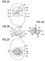
- Fig. 2A is a top view of an antenna base in the antenna of Fig. 1;
- Fig. 2B is a side view of the antenna base of Fig. 2A;
- Fig. 2C is a bottom view of the antenna base of Fig. 2A;
- Fig. 2D is a section view taken along a line IID-IID in Fig. 2B;
- Fig. 3A is a top view of a claw washer in the antenna of Fig. 1;
- Fig. 3B is a front view of the claw washer of Fig. 3A;
- Fig. 3C is a side view of the claw washer of Fig. 3A;
- Fig. 3D is a rear view of the claw washer of Fig. 3A;
- Fig. 3E is a bottom view of the claw washer of Fig. 3A;
- Fig. 4A is a top view of a provisional holder in the antenna of Fig. 1;
- Fig. 4B is a side view of the provisional holder of Fig. 4A;
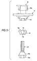
- Fig. 5 is a side view showing members constituting a mounting structure for the antenna of Fig. 1;
- Fig. 6A is a partially sectional side view showing a state that the antenna of Fig. 1 is provisionally fixed on a vehicle body;
- Fig. 6B is a schematic bottom view showing the state of Fig. 6A;
- Fig. 7A is a partially sectional side view showing a state that the antenna of Fig. 1 is plenarily fixed on the vehicle body;
- Fig. 7B is a schematic bottom view showing the state of Fig. 7A;
- Fig. 8A is a top view of an antenna base in an antenna according to a second embodiment of the invention;
- Fig. 8B is a side view of the antenna base of Fig. 8A;
- Fig. 8C is a bottom view of the antenna base of Fig. 8A;
- Fig. 8D is a section view taken along a line VIIID-VIIID in Fig. 8B;
- Fig. 9A is a top view of a claw washer in the antenna of Fig. 8A;
- Fig. 9B is a front view of the claw washer of Fig. 9A;
- Fig. 9C is a side view of the claw washer of Fig. 9A;
- Fig. 9D is a rear view of the claw washer of Fig. 9A;
- Fig. 9E is a bottom view of the claw washer of Fig. 9A;
- Fig. 10 is a side view showing members constituting a mounting structure for the antenna of Fig. 8A;
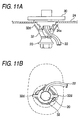
- Fig. 11A is a partially sectional side view showing a state that the antenna of Fig. 8A is provisionally fixed on a vehicle body;
- Fig. 11 B is a schematic bottom view showing the state of Fig. 11A;
- Fig. 12A is a partially sectional side view showing a state that the antenna of Fig. 8A is plenarily fixed on the vehicle body;
- Fig. 12B is a schematic bottom view showing the state of Fig. 12A;
- Fig. 13A is a top view of an antenna base in an antenna according to a third embodiment of the invention;
- Fig. 13B is a side view of the antenna base of Fig. 13A;
- Fig. 13C is a bottom view of the antenna base of Fig. 13A;
- Fig. 13D is a section view taken along a line XIIID-XIIID in Fig. 13B;
- Fig. 14 is a side view showing members constituting a mounting structure for the antenna of Fig. 13A;
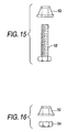
- Fig. 15 is a side view showing members constituting a modified example of the mounting structure for the antenna of Fig. 1;
- Fig. 16 is a side view showing members constituting a modified example of the mounting structure for the antenna of Fig. 13A;
- Fig. 17A is a side view of an antenna according to a fourth embodiment of the invention;
- Fig. 17B is a bottom view of the antenna of Fig. 17A;
- Fig. 17C is a front view of the antenna of Fig. 17A;
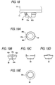
- Fig. 18 is an enlarged side view of a bottom part of the antenna of Fig. 17A;
- Fig. 19A is a top view of a claw washer in the antenna of Fig. 17A;
- Fig. 19B is a front view of the claw washer of Fig. 19A;
- Fig. 19C is a side view of the claw washer of Fig. 19A;
- Fig. 19D is a rear view of the claw washer of Fig. 19A;
- Fig. 19E is a bottom view of the claw washer of Fig. 19A;
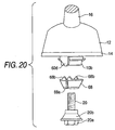
- Fig. 20 is a side view showing members constituting a mounting structure for the antenna of Fig. 17A;
- Fig. 21 is a partially sectional side view showing a state before the antenna of Fig. 17A is mounted on a vehicle body;
- Fig. 22 is a schematic bottom view showing a state that the antenna of Fig. 17A is provisionally fixed on the vehicle body;
- Fig. 23 is a schematic bottom view showing a state that the antenna of Fig. 17A is plenarily fixed on the vehicle body;
- Fig. 24 is a side view showing members constituting a mounting structure for an antenna according to a fifth embodiment of the invention;
- Fig. 25A is a front view of an antenna base in a related-art antenna;
- Fig. 25B is a side view of the antenna base of Fig. 25A;
- Fig. 26 is a partially sectional side view showing a state before the antenna of Fig. 25A is mounted on a vehicle body;
- Fig. 27A is a partially sectional side view showing a state that the antenna of Fig. 25A is plenarily fixed on the vehicle body; and
- Fig. 27B is a schematic bottom view showing the state of Fig. 27A.
- Embodiments of the invention will be described below in detail with reference to the accompanying drawings.
- Fig. 1 shows a vehicle antenna according to a first embodiment of the invention, wherein an
antenna base 10 is appropriately fixed in place within ahousing 12, and arubber pad 14 is provided on a lower face side of theantenna base 10. A proximal end portion of anantenna element 16 is fixed to an upper end portion of thehousing 12. and a circuit board (not shown) which includes an amplifier circuit is appropriately accommodated within thehousing 12. Abolt 20, on which aclaw washer 18 is fitted, is screwed into theantenna base 10 at a distal end thereof from therebelow so as to be integrated into theantenna base 10. Acable 22, which constitutes a signal transmission path or the like, is let out of theantenna base 10. - The vehicle antenna configured as has been described above is inserted into a
hole 24a opened in a roof or the like of avehicle body 24 from thereabove with thecable 22 and thebolt 20 and theclaw washer 18 passed through thehole 24a first, whereby the vehicle antenna is provisionally fixed to the vehicle body 24 (described later in detail). Furthermore, thebolt 20 that projects into an inside of the vehicle is fastened so that the vehicle antenna is fixed to thevehicle body 24 while an electric conductivity is secured. - As shown in Figs. 2A to 2D, the
antenna base 10 formed of metal comprises: aprotrusion 10a, which is formed substantially into a square shape in plan view, is provided on a bottom face of theantenna base 10; acylindrical portion 10b, provided at the center of theprotrusion 10a; and aninternal thread 10c engraved within thecylindrical portion 10b. A wedge-shapedmember 10d, which gets narrower as it extends downwards, is formed in such a manner as to extend from a comer of the substantiallysquare protrusion 10a to a circumferential face of thecylindrical portion 10b. Acable hole 10e, through which the cable is to be passed, is opened in the wedge-shapedmember 10d so as to form a through hole which penetrates through theantenna base 10 in a vertical direction. Arecess 10f is provided on an upper face of theantenna base 10 for accommodating therein a provisional holder 26 (described layer), andbosses 10g are provided on the upper face of theantenna base 10 to be used to clamp theprovisional holder 26 within therecess 10f.Holes 10h are opened in the upper face of theantenna base 10 in such a manner as to vertically penetrate through theantenna base 10 so as to allow the passage ofclaws 26a (described later) of theprovisional holder 26 therethrough. - As shown in Figs. 3A to 3E, the
claw washer 18 made of a sheet of metal is formed substantially into a truncated conical shape which gets narrower as it extends downwards. Theclaw washer 18 is partially cut to thereby form aslit 18a therein so as to be formed substantially into a C-shape as viewed from a top thereof. Then, threeclaws 18b are provided on an upper edge portion of theclaw washer 18 in such a manner as to project upwards therefrom. Furthermore, anotch 18c is continuously formed with theslit 18a so that the wedge-shapedmember 10d is inserted thereinto and thecable 22 is allowed to escape thereto. An outer diameter of the upper edge portion of theclaw washer 18 including theclaws 18b is set so as to pass through thehole 24a. - As shown in Figs. 4A and 4B, the
provisional holder 26 formed of elastic resin material comprisesclaws 26a extended from an upper connectingportion 26b. Opened in this connectingportion 26b areholes 26c into which thebosses 10g of theantenna base 10 are inserted to thereby be clamped. - As shown in Fig. 5, the
bolt 20 formed of metal includes ahead portion 20a of a hexagonal shape when viewed from a bottom thereof, and a truncated-conical portion 20b is formed on a bolt side of thehead portion 20a. This truncated-conical portion 20b is configured so as to become wider from an upper end to a lower end thereof in such a manner that an upper outer diameter is slightly smaller while a lower outer diameter is larger than a lower inner diameter of theclaw washer 18 in an original state. - The assembly of the respective members that have been described heretofore is implemented in such an arrangement as shown in Fig. 5. Firstly, the
provisional holder 26 is assembled on to theantenna base 10 from thereabove and is fixed thereto by being clamped appropriately. Furthermore, a distal end portion of thebolt 20 on which theclaw washer 18 is fitted is screwed into theinternal thread 10c in theantenna base 10 from therebelow to a slight extent, whereby thebolt 20 and theclaw washer 18 are integrated on to theantenna base 10. In implementing the assembly, theclaw washer 18 is provided to realize such a positional relationship that thenotch 18c therein is made to oppositely face the wedge-shapedmember 10d of theantenna base 10 so that the wedge-shapedmember 10d can be inserted into thenotch 18c. - In such an integrated state, as shown in Figs. 6A and 6B, the
cable 22 is firstly passed through thecable hole 10e in theantenna base 10 and is then inserted into thehole 24a in thevehicle body 24 from thereabove. Furthermore, theprotrusion 10a of theantenna base 10 is made to face thehole 24a which is formed substantially into a square shape. The substantially square shape of thehole 24a is slightly larger than the substantially square shape of theprotrusion 10a. Then, thebolt 20 and theclaw washer 18 are inserted into thehole 24a from thereabove, theclaws 26a of theprovisional holder 26 elastically deform so as to be allowed to be inserted into thehole 24a, and after having passed through thehole 24a, theclaws 26a elastically restore, whereby the hook portions at distal ends thereof are positioned at the circumferential edge portion of thehole 24a to thereby be caught thereon. In the state shown in Figs. 6A and 6B, theantenna base 10 is prevented from being dislodged upwards by theclaws 26a, whereby theantenna base 10 is provisionally fixed to thehole 24a. - Then, as shown in Figs. 7A and 7B, the
bolt 20 is screwed strongly into theinternal thread 10c in theantenna base 10, and theclaw washer 18 is deformed by the wedge-shapedmember 10d of theantenna base 10 and the truncated-conical portion 20b of thebolt 20 in such a manner that the diameter of the substantially C-shape thereof is increased, whereby theclaw washer 18 is opened further. Then, the outer diameter of the threeclaws 18b on the upper edge portion of theclaw washer 18 is increased so as to be larger than the diametrical dimension of thehole 24a, whereby theclaws 18b are positioned at the circumferential edge portion of thehole 24a. Furthermore, by continuing to tighten thebolt 20 strongly, theclaws 18b are made to bite into the inner face of thevehicle body 24, whereby theantenna base 10 is fixed to thevehicle body 24, and an electrical conduction is established in thevehicle body 24 via thebolt 20 and theclaw washer 18. - Here, during the operation of expanding the diameter of the substantially C-shape of the
claw washer 18, friction force causes a force to act on theclaw washer 18 which attempts to rotate thewasher 18 around an axis thereof together with thebolt 20 in conjunction with the rotational tightening of thebolt 20. However, since one end of theslit 18a in theclaw washer 18 is in abutment with the wedge-shapedmember 10d of theantenna base 10 to thereby be restricted in position, only the other end of theslit 18a is expanded in the direction in which theclaw washer 18 is attempted to be rotated together with thebolt 20, whereby thenotch 18c of theslit 18a is also expanded. Then, thecable 22, which is passed through thecable hole 10e provided in the central portion of the wedge-shapedmember 10d, is surely kept remaining within thenotch 18c, so as to be prevented from being brought into abutment with theclaw washer 18, thereby making it possible to prevent thecable 22 from being damaged. - In the first embodiment, the
cable hole 10e through which thecable 22 is passed is provided in the wedge-shapedmember 10d of theantenna base 10. However, an appropriate notch through which thecable 22 is passed may be provided in the wedge-shapedmember 10d of theantenna base 10 instead of thecable hole 10e. - In the first embodiment, the
claws 26a of theprovisional holder 26 are inserted into thehole 24a so as to be hooked on the circumferential edge portion of thehole 24a. However, holes may be opened separately from thehole 24a opened in thevehicle body 24 so that theclaws 26a are inserted to be caught therein. - Next, a second embodiment of the invention will be described with reference to Figs. 8A to 12B. Components similar to those in the first embodiment will be designated by the same reference numerals and repetitive explanations for those will be omitted.
- In the second embodiment, what is largely different from the first embodiment resides in a temporarily fixing structure. As shown in Figs. 8A to 8D, an
antenna base 30 formed of metal comprises: aprotrusion 30a, which is formed substantially into a square shape as viewed from a top thereof, and is provided on a bottom face of theantenna base 30; acylindrical portion 30b, which is provided at the center of theprotrusion 30a; and aninternal thread 30c, which is engraved within thecylindrical portion 30b. A wedge-shapedmember 30d, which gets narrower as it extends downwards, is formed in such a manner as to extend from a corner of the substantiallysquare protrusion 30a to a circumferential face of thecylindrical portion 30b. Acable hole 30e, through which the cable is to be passed, is opened in the wedge-shapedmember 30d so as to form a through hole which penetrates through theantenna base 30 in a vertical direction.Grooves 30f are provided at two corners of the substantiallysquare protrusion 30a where the wedge-shapedmember 30d is not provided, for receiving an elastic deformation ofclaws 32d of a claw washer 32 (described later). There is no structure corresponding to therecess 10f, thebosses 10g and theholes 10h which are provided in the first embodiment. - As shown in Figs. 9A to 9E, the
claw washer 32 is made of a sheet of elastic conductive metal and formed substantially into a truncated conical shape which gets narrower as it extends downwards. Theclaw washer 32 is partially cut to thereby form aslit 32a therein so as to be formed substantially into a C-shape as viewed from a top thereof. Then, threeclaws 32b are provided on an upper edge portion of theclaw washer 18 in such a manner as to project upwards therefrom. An outer diameter of the upper edge portion of theclaw washer 32 including theclaws 32b is set is set so as to pass through thehole 24a. Anotch 32c is continuously formed with theslit 32a so that the wedge-shapedmember 30d is inserted thereinto and thecable 22 is allowed to escape thereto. Twoclaws 32d are provided on the upper edge portion of theclaw washer 32 at oppositely facing positions which are 90° apart in clockwise and counterclockwise directions from theslit 32a as viewed from the top thereof in such a manner as to project upwards from the upper edge portion so as to be gradually spaced apart from each other as they extend upwards. Theclaws 32d are made longer than theclaws 32b, and a distance between distal ends thereof becomes larger than the outer diameter of the upper edge portion of theclaw washer 32 including theclaws 32b. - Then, as shown in Fig. 10, a distal end portion of the
bolt 20 on which theclaw washer 32 is fitted is screwed into theantenna base 30 from therebelow, whereby thebolt 20 and theclaw washer 32 are integrated on to theantenna base 20. As this occurs, theantenna base 30, thebolt 20 and theclaw washer 30 are disposed in a positional relationship in which thenotch 32c in theclaw washer 32 faces the wedge-shapedmember 30d of theantenna base 30. - In such an integrated state, as shown in Figs. 11 A and 11 B, the
cable 22 is firstly passed through thecable hole 30e in theantenna base 30 and is then inserted into thehole 24a in thevehicle body 24 from thereabove. Furthermore, theprotrusion 30a of theantenna base 30 is made to face thehole 24a. Then, when thebolt 20 and theclaw washer 32 are inserted into thehole 24a from thereabove, theclaws 32d of theclaw washer 32 elastically deform so as to be allowed to be inserted into thehole 24a, and after having passed through thehole 24a, theclaws 32d elastically restore, whereby the distal ends thereof are positioned at the inner face of the circumferential edge portion of thehole 24a. In the state shown in Figs. 11A and 11 B, theantenna base 30 is prevented from being dislodged upwards by theclaws 32d, whereby theantenna base 30 is provisionally fixed to thehole 24a. When theclaws 32d pass through thehole 24a, theclaws 32d are inserted into thegrooves 30f on theantenna base 30 to thereby permit an elastic deformation thereof in a direction in which the outer diameter thereof is reduced. - Then, as shown in Figs. 12A and 12B, the
bolt 20 is screwed strongly into theinternal thread 30c in theantenna base 30, theclaw washer 32 is opened by the wedge-shapedmember 30d of theantenna base 30 and the truncated-conical portion 20b of thebolt 20 in such a manner that the diameter of the substantially C-shape thereof is increased, whereby the outer diameter of the threeclaws 32b on the upper edge portion of theclaw washer 32 is increased, and theclaws 32b are positioned at the circumferential edge portion of thehole 24a. By continuing to tighten thebolt 20 strongly, theclaws 32b are made to bite into the inner face of thevehicle body 24, whereby theantenna base 30 is fixed to thevehicle body 24, and an electrical conduction is established in thevehicle body 24 via thebolt 20 and theclaw washer 32. Then, as to the enlargement of the diameter of the substantially C-shapedclaw washer 32, as with the first embodiment, since one end of theslit 32a in theclaw washer 32 is restricted in position, only the other end of theslit 32a is expanded in a direction in which theclaw washer 32 is attempted to be rotated together with thebolt 20 to thereby expand thenotch 32c. Here, since thecable 22 which is passed through thecable hole 30e formed at the central portion of the wedge-shapedmember 30d is allowed to surely stay within thenotch 32c, thecable 22 can be prevented from being damaged. - Next, a third embodiment of the invention will be described with reference to Figs. 13A to 14. Components similar to those in the first embodiment will be designated by the same reference numerals and repetitive explanations for those will be omitted.
- In the third embodiment, what is largely different from the first embodiment resides in that a bolt is integrally provided on an antenna base in such a manner as to project therefrom. As shown in Figs. 13A to 13D, a
bolt 42 is integrally provided on anantenna base 40 in such a manner as to project downwards therefrom, in place of theinternal thread 10c provided in theantenna base 10 in the first embodiment. As to the other components, as with the first embodiment, there are provided aprotrusion 40a, acylindrical portion 40b, a wedge-shapedmember 40d, acable hole 40e, arecess 40f,bosses 40g andholes 40h. - As shown in Fig. 14, a
nut 44 which is screwed on thebolt 42 is formed of metal and includes a truncated-conical portion 44a which is formed to become wider as it extends from an upper end to a lower end thereof in such a manner that an upper outer diameter is smaller while a lower outer diameter thereof is larger than a lower inner diameter of theclaw washer 18. - Then, the respective members are arranged as shown in Fig. 14, and the
provisional holder 26 is assembled on to theantenna base 40, furthermore, theclaw washer 18 is fitted on thebolt 42 so as to establish a positional relationship in which thenotch 18c in theclaw washer 18 faces the wedge-shapedmember 40d of theantenna base 40, and thenut 44 is screwed on a lower end portion of thebolt 42, whereby theprovisional holder 26, theclaw washer 18 and thenut 44 are integrated on to theantenna base 40. Then, the integrated members so formed are inserted into thehole 24a in thevehicle body 24 from thereabove, so that the integrated members are provisionally fixed to thevehicle body 24 by theprovisional holder 26. Furthermore, thenut 44 is tightened strongly, so that theantenna base 40 is fixed to thevehicle body 24 and an electric conduction is obtained. - In the third embodiment, the provisional fixation is designed to be attained using the
provisional holder 26 formed of a resin material. However, the provisional fixation may be designed to be attained, as with the second embodiment, using theclaws 32d which are provided on theclaw washer 32 in place of the resinprovisional holder 26. - In place of the
bolt 20 in the first embodiment, a truncated-conical bush 50 may be fitted on anormal bolt 52 having a head portion as shown in Fig. 15. Thisbush 50 is formed to become wider as it extends from an upper end to a lower end thereof in such a manner that an upper outer diameter is smaller while a lower outer diameter thereof is larger than a lower inner diameter of theclaw washer 18. - The
nut 44 of the third embodiment may be divided into the truncated-conical bush 50 and anormal nut 54. Since thebush 50 is interposed between theclaw washer 18 and the head of thebolt 52 and thebush 50 is also interposed between theclaw washer 18 and thenut 54, a force acting on theclaw washer 18 can be reduced which attempts to rotate theclaw washer 18 around an axis thereof together with thebolt 52 and thenut 54 in conjunction with the rotation of thebolt 52 and thenut 54. Moreover, since the lower inner diameter of theclaw washer 18 can be expanded by thebush 50, commercially available bolts and nuts can be used for thebolt 52 and thenut 54. - Next, a fourth embodiment of the invention will be described with reference to Figs. 17A to 23. Components similar to those in the first embodiment will be designated by the same reference numerals and repetitive explanations for those will be omitted.
- In this embodiment, as shown in Figs. 17A to 18, a wedge-shaped
member 60d, which becomes narrower as it extends downwards, is formed in such a manner as to extend between theprotrusion 10a and a circumferential face of thecylindrical portion 10b. This wedge-shapedmember 60d is provided in such a manner as to be deviated through an appropriate angle in an opposite direction to a rotational direction of thebolt 20 relative to a longitudinal center line C of theantenna base 10. Moreover, aslope 60e is formed on an opposite face of the wedge-shapedmember 60d to the rotational direction of thebolt 20 in which thebolt 20 is screwed to be tightened in such a manner as to extend to the vicinity of a lower face of theprotrusion 10a. In addition, acable hole 60f is opened vertically through theprotrusion 10a, and thecable 22 is let out therefrom. Theprotrusion 10a and the like which are provided on the lower face of theantenna base 10 are provided in such a manner as to protrude downwards from ahole 14a provided at a substantially central portion of therubber pad 14. - As shown in Figs. 19A to 19E, a
claw washer 68 is made of a sheet of conductive metal and is formed substantially into a truncated conical shape which becomes narrower as it extends downwards, theclaw washer 68 being formed substantially C-shape, as viewed from a top thereof, by being partially cut to form aslit 68a. Then, threeclaws 68b are provided on an upper edge portion of theclaw washer 68 at three locations of both end portions of theslit 68a and an opposite position to theslit 68a in such a manner as to project upwards therefrom. An outer diameter of the upper edge portion of theclaw washer 68 including theclaws 68b is set to such a dimension that allows theclaws 68b to pass through thehole 24a in their natural state. In addition, an upper inner diameter of the upper edge portion of theclaw washer 68 is set so as to be slightly larger than an outer diameter of thecylindrical portion 10b in its natural state. - As shown in Fig. 20, the truncated-
conical portion 20b of thebolt 20 is configured so as to become wider in a tapered shape from an upper end to a lower end thereof in such a manner that an upper outer diameter is slightly smaller while a lower outer diameter thereof is larger than a lower inner diameter of theclaw washer 68 in its original state. - The assembly of the aforesaid respective members is implemented as arranged in Fig. 20, and a distal end portion of the
bolt 20 on which theclaw washer 68 is firstly fitted from therebelow is screwed into theinternal thread 10c in theantenna base 10, whereby thebolt 20 and theclaw washer 68 are integrated on to theantenna base 10 as shown in Fig. 21. Incidentally, theantenna base 10 and theclaw washer 68 are disposed in such a positional relationship that theslit 68a in theclaw washer 68 faces the wedge-shapedmember 60d of theantenna base 10. - The integrated members are inserted into the
hole 24a in thevehicle body 24 from thereabove. Here, thehole 24a in thevehicle body 24 is opened in a dimension which is slightly larger than a horizontal shape of theprotrusion 10a of theantenna base 10. Then, when theprotrusion 10a is inserted into thehole 24a, the rotation of thebolt 20 around the axis thereof is restricted and the positional deviation of thebolt 20 in a direction normal thereto is also restricted. Furthermore, with theprotrusion 10a inserted into thehole 24a, theclaws 26 are locked on the inner face of the circumferential edge portion of thehole 24a as shown in Fig. 22, whereby theantenna base 10 is restricted from being dislodged upwards. Thus, the antenna assembly is put in such a state that the assembly is provisionally fixed to thehole 24a in thevehicle body 24. - When the
bolt 20 is strongly screwed into theinternal thread 10c in theantenna base 10, theclaw washer 68 is deformed by the wedge-shapedmember 60d and thecylindrical portion 10b of theantenna base 10 and the truncated-conical portion 20b of thebolt 20 in such a manner that the diameter of the substantially C-shape thereof is increased, whereby theclaw washer 68 is opened further. Then, the upper edge portion of theclaw washer 68 is expanded so that theclaws 68b are positioned on the inner face of the circumferential edge portion of thehole 24a. Furthermore, by continuing to strongly tighten thebolt 20, theclaws 68b are made to bite into the inner face of thevehicle body 24 while being deviated in their positions, whereby theantenna base 10 is fixed to thevehicle body 24 while an electrical conduction to thevehicle body 24 is established via thebolt 20 and theclaw washer 68. - In the operation of expanding the
claw washer 68, a force is caused to act on theclaw washer 68 which attempts to rotate theclaw washer 68 around the axis thereof together with thebolt 20 by a friction force generated in conjunction with the tightening rotation of thebolt 20. However, the one end portion of theslit 68a is in abutment with theslope 60e of the wedge-shapedmember 60d of theantenna base 10 and hence, the position of the one end portion of theslit 68a is restricted. Since the one end portion of theslit 68a is deviated in position in an opposite direction to the direction in which theclaw washer 68 is attempted to be rotated together with thebolt 20, as shown in Fig. 23, theclaw 68b situated at the one end portion of theslit 68a is moved from P1 to Q1 so as to face the inner face of the circumferential edge portion of thehole 24a. In addition, theclaw 68b situated at the other end portion of theslit 68a is expanded in the direction in which theclaw washer 68 is attempted to be rotated together with thebolt 20 and is then moved largely from P2 to Q2, whereby theclaw 68b situated at the other end portion of theslit 68a is positioned so as to face an opposite different position on the circumferential edge portion of thehole 24a. Furthermore, in conjunction with the enlargement in diameter of theclaw washer 68, the remainingclaw 68b that is provided opposite to theslit 68a is moved from P3 to Q3, so that theclaw 68b is also positioned to face the inner face of the circumferential edge portion of thehole 24a. - Thus, when the diameter of the
claw washer 68 is expanded, the distance over which eachclaw 68b provided at both the end portions of theslit 68a is moved differs largely between the movement to the direction in which theclaw washer 68 is attempted to be rotated together with thebolt 20 and the movement to the opposite direction thereto as thebolt 20 is tightened. Then, by providing the wedge-shapedmember 60d in such a manner as to be deviated through an appropriate angle in the opposite direction to the direction in which theclaw washer 68 is attempted to be rotated together with thebolt 20 relative to the longitudinal center line C of theantenna base 10 in accordance with the difference in the distance over which theclaws 68b are so moved, theclaws 68b which are situated at both the end portions of theslit 68a can be positioned substantially symmetrical with each other with respect to the longitudinal center line C of theantenna base 10 when theclaw washer 68 is expanded. - Accordingly, the
claws 68b which are situated at both the end portions of theslit 68a can be made to face the inner face of the circumferential edge portion at the substantially symmetrical positions on both the sides of thehole 24a. In addition, theslope 60e of the wedge-shapedmember 60d not only restricts the movement of the position of theclaw 68b situated at the one end portion of theslit 68a in the direction in which theclaw washer 68 is attempted to be rotated together with thebolt 20 but also allows the position of theclaw 68b so situated to move in the opposite direction to the direction in which theclaw washer 68 is attempted to be rotated together with thebolt 20. Consequently, by setting theslope 60e appropriately, the position of theclaw 68b situated at the one end portion of theslit 68a can be surely made to face the circumferential edge portion of thehole 24a. - Next, a fifth embodiment of the invention will be described with reference to Fig. 24. Components similar to those in the fourth embodiment will be designated by the same reference numerals and repetitive explanations for those will be omitted.
- In the second embodiment, what largely differs from the fourth embodiment resides in that a
bolt 42 is integrally provided on anantenna base 40 in such a manner as to project downwardly therefrom. - Then, a
nut 44 formed of metal and including a truncated-conical portion 44a is screwed on thebolt 42. This truncated-conical portion 44a is formed so as to become wider from an upper end to a lower end thereof in such a manner that an upper outer diameter is smaller while a lower outer diameter is larger than a lower inner diameter of theclaw washer 68. - Then, the respective members are arranged as shown in Fig. 24, and the
claw washer 68 is fitted on thebolt 42 on theantenna base 10 so as to realize a positional relationship in which theslit 68a in theclaw washer 68 faces the wedge-shapedmember 60d of theantenna base 10, and thenut 44 is screwed on a lower end portion of thebolt 42, whereby theclaw washer 68 and thenut 44 are integrated on to theantenna base 40. Then, similarly to the fourth embodiment, the integrated members so formed are inserted into thehole 24 from above thevehicle body 24 so as to be provisionally fixed byclaws 26. When thenut 44 is tightened strongly, theantenna base 40 is fixed to thevehicle body 24 while obtaining an electrical conduction. - In place of the
bolt 20 in the fourth embodiment, a truncated-conical bush 50 may be fitted on anormal bolt 52 having a head portion as shown in Fig. 15. Thisbush 50 is formed to become wider as it extends from an upper end to a lower end thereof in such a manner that an upper outer diameter is smaller while a lower outer diameter thereof is larger than a lower inner diameter of theclaw washer 68. - The
nut 44 of the fifth embodiment may be divided into the truncated-conical bush 50 and anormal nut 54. Since thebush 50 is interposed between theclaw washer 68 and the head of thebolt 52 and thebush 50 is also interposed between theclaw washer 68 and thenut 54, a force acting on theclaw washer 68 can be reduced which attempts to rotate theclaw washer 68 around an axis thereof together with thebolt 52 and thenut 54 in conjunction with the rotation of thebolt 52 and thenut 54. Moreover, since the lower inner diameter of theclaw washer 68 can be expanded by thebush 50, commercially available bolts and nuts can be used for thebolt 52 and thenut 54. - Although the present invention has been shown and described with reference to specific preferred embodiments, various changes and modifications will be apparent to those skilled in the art from the teachings herein. Such changes and modifications as are obvious are deemed to come within the spirit, scope and contemplation of the invention as defined in the appended claims.
Claims (7)
- A structure for mounting an antenna device on a first side of a panel body, the structure comprising:a first fixation member, having a tubular body including a first end having a first width, a second end, and a slit connecting the first end and the second end;a protrusion, protruded from the antenna device and fitted into the first end of the first fixation member;a second fixation member, fitted into the second end of the first fixation member while being coupled with the protrusion in a screwing manner;a wedge member, provided on the protrusion and formed with a cutout portion, the wedge member being configured to be fitted into the slit when the protrusion and the second fixation member are in a first screwing position, and configured to expand the slit when the protrusion and the second fixation member are in a second screwing position where the protrusion and the second fixation member are closed to each other than the first screwing position; anda cable, extending from the antenna device and led to a second side of the panel body while passing through the cutout portion of the wedge member and an aperture formed in the panel body, wherein:the first width is smaller than the aperture when the protrusion and the second fixation member are in the first screwing position, so that the protrusion, the first fixation member and the second fixation member are allowed to pass through the aperture from the first side to the second side; andthe slit is expanded such that the first end of the first fixation member is made to have a second width which is greater than the aperture when the protrusion and the second fixation member are in the second position.
- The structure as set forth in claim 1, wherein the second fixation member is a bolt member adapted to be screwed into a hole formed in the protrusion, and the bolt has a head portion adapted to be fitted into the second end of the first fixing member to assist the wedge member to expand the slit.
- The structure as set forth in claim 1, wherein the second fixation member is a nut member adapted to be fitted into the second end of the first fixing member and screwed on a bolt formed on the protrusion to assist the wedge member to expand the slit of the first fixation member.
- A structure for mounting an antenna device on a first side of a panel body, the structure comprising:a first fixation member, having a tubular body including a first end having a first width, a second end, and a slit connecting the first end and the second end;a plurality of claws, provided on the first end of the first fixation member at positions that are both sides of the slit, the claws being adapted to be bite into a second side of the panel body;a protrusion, protruded from the antenna device and fitted into the first end of the first fixation member;a second fixation member, fitted into the second end of the first fixation member while being coupled with the protrusion in a screwing manner;a wedge member, provided on the protrusion, the wedge member being configured to be fitted into the slit when the protrusion and the second fixation member are in a first screwing position, and configured to expand the slit when the protrusion and the second fixation member are in a second screwing position where the protrusion and the second fixation member are closed to each other than the first screwing position, wherein:the first width is smaller than the aperture when the protrusion and the second fixation member are in the first screwing position, so that the protrusion, the first fixation member and the second fixation member are allowed to pass through the aperture from the first side to the second side;the slit is expanded such that the first end of the first fixation member is made to have a second width which is greater than the aperture when the protrusion and the second fixation member are in the second position;the second fixation member is rotated in a first direction to be placed in the second screwing position; andthe wedge member has a slope face configured such that one of the claws, which is moved in the first direction in accompany with the rotation of the second fixation member, is abutted against the slope face and guided in a second direction opposite to the first direction while the second fixation member is moved to the second screwing member.
- The structure as set forth in claim 4, wherein the wedge member is arranged at a position that is deviated from a center line of the aperture in the second direction.
- The structure as set forth in claim 4, wherein the second fixation member is a bolt member adapted to be screwed into a hole formed in the protrusion, and the bolt has a head portion adapted to be fitted into the second end of the first fixing member to assist the wedge member to expand the slit.
- The structure as set forth in claim 4, wherein the second fixation member is a nut member adapted to be fitted into the second end of the first fixing member and screwed on a bolt formed on the protrusion to assist the wedge member to expand the slit of the first fixation member.
Applications Claiming Priority (2)
| Application Number | Priority Date | Filing Date | Title |
|---|---|---|---|
| JP2004308804A JP4198666B2 (en) | 2004-10-22 | 2004-10-22 | Antenna mounting structure |
| JP2005214831A JP4780640B2 (en) | 2005-07-25 | 2005-07-25 | Antenna mounting structure |
Publications (3)
| Publication Number | Publication Date |
|---|---|
| EP1650827A2 true EP1650827A2 (en) | 2006-04-26 |
| EP1650827A3 EP1650827A3 (en) | 2006-05-10 |
| EP1650827B1 EP1650827B1 (en) | 2009-07-22 |
Family
ID=35507612
Family Applications (1)
| Application Number | Title | Priority Date | Filing Date |
|---|---|---|---|
| EP05022890A Expired - Lifetime EP1650827B1 (en) | 2004-10-22 | 2005-10-20 | Antenna mounting structure |
Country Status (3)
| Country | Link |
|---|---|
| EP (1) | EP1650827B1 (en) |
| KR (1) | KR101151946B1 (en) |
| DE (1) | DE602005015528D1 (en) |
Cited By (6)
| Publication number | Priority date | Publication date | Assignee | Title |
|---|---|---|---|---|
| EP2602866A1 (en) * | 2011-12-08 | 2013-06-12 | Fiamm France | device including a base plate for an antenna. |
| GB2548995A (en) * | 2016-03-28 | 2017-10-04 | Taoglas Group Holdings | Antenna systems and methods for incorporating into a body panel |
| US9966707B2 (en) * | 2006-12-01 | 2018-05-08 | Kathrein-Werke Kg | Device for fastening an attached part, in particular in the form of a motor vehicle antenna |
| WO2019048329A1 (en) * | 2017-09-05 | 2019-03-14 | Hirschmann Car Communication Gmbh | MOUNTING OF A MODULARLY TRAINED ANCHOR ANTENNA |
| US10403968B2 (en) | 2016-03-28 | 2019-09-03 | Taoglas Group Holdings Limited | Antenna systems and methods for incorporating into a body panel |
| CN112886216A (en) * | 2016-10-21 | 2021-06-01 | 株式会社友华 | Vehicle-mounted antenna device and antenna system |
Families Citing this family (2)
| Publication number | Priority date | Publication date | Assignee | Title |
|---|---|---|---|---|
| KR100859546B1 (en) * | 2007-06-05 | 2008-09-22 | 알에프컨트롤스 주식회사 | Fixture for the external antenna of the vehicle |
| KR101810508B1 (en) | 2016-05-12 | 2017-12-20 | 주식회사 케이엠더블유 | antenna cable connecting module and method of producing same |
Family Cites Families (5)
| Publication number | Priority date | Publication date | Assignee | Title |
|---|---|---|---|---|
| US2392491A (en) * | 1944-06-10 | 1946-01-08 | Franklin Perry J | Compound rivet |
| US7004666B2 (en) * | 2001-10-09 | 2006-02-28 | Tyco Electronics Corporation | Quick-attach automotive antenna mounting assembly |
| DE10210593B4 (en) * | 2002-03-11 | 2007-08-02 | Wilhelm Sihn Jr. Gmbh & Co. Kg | Fastening device for a vehicle antenna |
| US6714171B2 (en) * | 2002-06-14 | 2004-03-30 | Centurion Wireless Technologies, Inc. | Antenna mounting apparatuses and methods |
| DE202004007160U1 (en) * | 2004-04-07 | 2004-07-15 | Wilhelm Sihn Jr. Gmbh & Co. Kg | Vehicle antenna mounting unit has support with small conducting contact using protrusions compresses between unit and antenna foot by metal screw |
-
2005
- 2005-10-20 DE DE602005015528T patent/DE602005015528D1/en not_active Expired - Lifetime
- 2005-10-20 EP EP05022890A patent/EP1650827B1/en not_active Expired - Lifetime
- 2005-10-21 KR KR1020050099840A patent/KR101151946B1/en not_active Expired - Fee Related
Cited By (8)
| Publication number | Priority date | Publication date | Assignee | Title |
|---|---|---|---|---|
| US9966707B2 (en) * | 2006-12-01 | 2018-05-08 | Kathrein-Werke Kg | Device for fastening an attached part, in particular in the form of a motor vehicle antenna |
| EP2602866A1 (en) * | 2011-12-08 | 2013-06-12 | Fiamm France | device including a base plate for an antenna. |
| FR2984019A1 (en) * | 2011-12-08 | 2013-06-14 | Sce Groupe Fiamm | ANTENNA EMBASE DEVICE EQUIPPED WITH A FREE PASSAGE THROUGH THE ANTENNA SOLE |
| GB2548995A (en) * | 2016-03-28 | 2017-10-04 | Taoglas Group Holdings | Antenna systems and methods for incorporating into a body panel |
| US10403968B2 (en) | 2016-03-28 | 2019-09-03 | Taoglas Group Holdings Limited | Antenna systems and methods for incorporating into a body panel |
| CN112886216A (en) * | 2016-10-21 | 2021-06-01 | 株式会社友华 | Vehicle-mounted antenna device and antenna system |
| CN112886216B (en) * | 2016-10-21 | 2024-02-13 | 株式会社友华 | Vehicle-mounted antenna device and antenna system |
| WO2019048329A1 (en) * | 2017-09-05 | 2019-03-14 | Hirschmann Car Communication Gmbh | MOUNTING OF A MODULARLY TRAINED ANCHOR ANTENNA |
Also Published As
| Publication number | Publication date |
|---|---|
| EP1650827A3 (en) | 2006-05-10 |
| KR20060049141A (en) | 2006-05-18 |
| KR101151946B1 (en) | 2012-06-01 |
| EP1650827B1 (en) | 2009-07-22 |
| DE602005015528D1 (en) | 2009-09-03 |
Similar Documents
| Publication | Publication Date | Title |
|---|---|---|
| KR100872756B1 (en) | Vehicle roof antenna mounting assembly | |
| US7046207B2 (en) | Antenna mounting structure | |
| US20050237248A1 (en) | Vehicle roof antenna attachment | |
| EP1650827B1 (en) | Antenna mounting structure | |
| US7274341B2 (en) | Antenna mounting structure | |
| US5066246A (en) | Mounting bracket for an electrical connector | |
| US6805524B2 (en) | Screw grommet | |
| KR890701909A (en) | Method and apparatus for mounting parts on printed circuit board | |
| KR920009598B1 (en) | Fastening Mechanism | |
| JP4283136B2 (en) | Fixed structure, protector and electrical junction box | |
| KR101025572B1 (en) | Battery terminal coupler for vehicle using tightening nut | |
| JP2008280794A (en) | Reinforcement plate for folded plate hanging bracket | |
| JPH0515737Y2 (en) | ||
| JP4780640B2 (en) | Antenna mounting structure | |
| JPH0676867A (en) | Earth terminal | |
| JP4057022B2 (en) | Antenna mounting device | |
| US7186153B2 (en) | Side entry terminal pin | |
| US20240380094A1 (en) | Fastening arrangement for fastening a device housing of a device to a vehicle panel of a motor vehicle, and motor vehicle and device | |
| KR102123409B1 (en) | Terminal for earth | |
| CN218062791U (en) | Fan blade safety structure and fan | |
| KR20230156980A (en) | a bolt and a nut in a connector | |
| JPH09245767A (en) | Battery terminal | |
| KR100671735B1 (en) | Bolt and Nut Structure of Automotive Connectors | |
| JP4134026B2 (en) | Fusible link mounting method and fusible link / terminal connection structure | |
| JPH0550139U (en) | bolt |
Legal Events
| Date | Code | Title | Description |
|---|---|---|---|
| PUAI | Public reference made under article 153(3) epc to a published international application that has entered the european phase |
Free format text: ORIGINAL CODE: 0009012 |
|
| PUAL | Search report despatched |
Free format text: ORIGINAL CODE: 0009013 |
|
| AK | Designated contracting states |
Kind code of ref document: A2 Designated state(s): AT BE BG CH CY CZ DE DK EE ES FI FR GB GR HU IE IS IT LI LT LU LV MC NL PL PT RO SE SI SK TR |
|
| AX | Request for extension of the european patent |
Extension state: AL BA HR MK YU |
|
| AK | Designated contracting states |
Kind code of ref document: A3 Designated state(s): AT BE BG CH CY CZ DE DK EE ES FI FR GB GR HU IE IS IT LI LT LU LV MC NL PL PT RO SE SI SK TR |
|
| AX | Request for extension of the european patent |
Extension state: AL BA HR MK YU |
|
| 17P | Request for examination filed |
Effective date: 20061109 |
|
| AKX | Designation fees paid |
Designated state(s): DE FR GB |
|
| 17Q | First examination report despatched |
Effective date: 20070702 |
|
| GRAP | Despatch of communication of intention to grant a patent |
Free format text: ORIGINAL CODE: EPIDOSNIGR1 |
|
| GRAS | Grant fee paid |
Free format text: ORIGINAL CODE: EPIDOSNIGR3 |
|
| GRAA | (expected) grant |
Free format text: ORIGINAL CODE: 0009210 |
|
| AK | Designated contracting states |
Kind code of ref document: B1 Designated state(s): DE FR GB |
|
| REG | Reference to a national code |
Ref country code: GB Ref legal event code: FG4D |
|
| REF | Corresponds to: |
Ref document number: 602005015528 Country of ref document: DE Date of ref document: 20090903 Kind code of ref document: P |
|
| PLBE | No opposition filed within time limit |
Free format text: ORIGINAL CODE: 0009261 |
|
| STAA | Information on the status of an ep patent application or granted ep patent |
Free format text: STATUS: NO OPPOSITION FILED WITHIN TIME LIMIT |
|
| 26N | No opposition filed |
Effective date: 20100423 |
|
| PGFP | Annual fee paid to national office [announced via postgrant information from national office to epo] |
Ref country code: GB Payment date: 20131016 Year of fee payment: 9 Ref country code: FR Payment date: 20131009 Year of fee payment: 9 |
|
| PGFP | Annual fee paid to national office [announced via postgrant information from national office to epo] |
Ref country code: DE Payment date: 20141014 Year of fee payment: 10 |
|
| GBPC | Gb: european patent ceased through non-payment of renewal fee |
Effective date: 20141020 |
|
| PG25 | Lapsed in a contracting state [announced via postgrant information from national office to epo] |
Ref country code: GB Free format text: LAPSE BECAUSE OF NON-PAYMENT OF DUE FEES Effective date: 20141020 |
|
| REG | Reference to a national code |
Ref country code: FR Ref legal event code: ST Effective date: 20150630 |
|
| PG25 | Lapsed in a contracting state [announced via postgrant information from national office to epo] |
Ref country code: FR Free format text: LAPSE BECAUSE OF NON-PAYMENT OF DUE FEES Effective date: 20141031 |
|
| REG | Reference to a national code |
Ref country code: DE Ref legal event code: R119 Ref document number: 602005015528 Country of ref document: DE |
|
| PG25 | Lapsed in a contracting state [announced via postgrant information from national office to epo] |
Ref country code: DE Free format text: LAPSE BECAUSE OF NON-PAYMENT OF DUE FEES Effective date: 20160503 |