EP1650754A1 - Storage device for recording media - Google Patents
Storage device for recording media Download PDFInfo
- Publication number
- EP1650754A1 EP1650754A1 EP06001770A EP06001770A EP1650754A1 EP 1650754 A1 EP1650754 A1 EP 1650754A1 EP 06001770 A EP06001770 A EP 06001770A EP 06001770 A EP06001770 A EP 06001770A EP 1650754 A1 EP1650754 A1 EP 1650754A1
- Authority
- EP
- European Patent Office
- Prior art keywords
- separating
- holders
- holder
- accommodating
- recording media
- Prior art date
- Legal status (The legal status is an assumption and is not a legal conclusion. Google has not performed a legal analysis and makes no representation as to the accuracy of the status listed.)
- Granted
Links
Images


Classifications
-
- G—PHYSICS
- G11—INFORMATION STORAGE
- G11B—INFORMATION STORAGE BASED ON RELATIVE MOVEMENT BETWEEN RECORD CARRIER AND TRANSDUCER
- G11B17/00—Guiding record carriers not specifically of filamentary or web form, or of supports therefor
- G11B17/22—Guiding record carriers not specifically of filamentary or web form, or of supports therefor from random access magazine of disc records
-
- G—PHYSICS
- G11—INFORMATION STORAGE
- G11B—INFORMATION STORAGE BASED ON RELATIVE MOVEMENT BETWEEN RECORD CARRIER AND TRANSDUCER
- G11B17/00—Guiding record carriers not specifically of filamentary or web form, or of supports therefor
- G11B17/02—Details
- G11B17/022—Positioning or locking of single discs
-
- G—PHYSICS
- G11—INFORMATION STORAGE
- G11B—INFORMATION STORAGE BASED ON RELATIVE MOVEMENT BETWEEN RECORD CARRIER AND TRANSDUCER
- G11B17/00—Guiding record carriers not specifically of filamentary or web form, or of supports therefor
- G11B17/02—Details
- G11B17/04—Feeding or guiding single record carrier to or from transducer unit
- G11B17/05—Feeding or guiding single record carrier to or from transducer unit specially adapted for discs not contained within cartridges
- G11B17/053—Indirect insertion, i.e. with external loading means
- G11B17/056—Indirect insertion, i.e. with external loading means with sliding loading means
Abstract
a selection mechanism (54) for moving the plurality of holders (39) in its entirety along the stacking direction, and for selecting the position at which the separating members (56) enter between the holders (39); and
a separating mechanism (53, 86, 87) for causing the separating members (56) to enter between the holders (39) and thereby separating the holders (39) such that a playback mechanism (25) for playing back and/or for recording information can move into the space created by the separation of the holders (39) and transfer a recording media (24) to or from a holder (39).
Description
- The present invention relates to a recording media accommodating apparatus capable of accommodating a plurality of flat-shaped recording media and playing back information recorded on an arbitrarily selected one of the recording media.
- There have been known heretofore automotive audio systems, navigation systems, and the like, that are equipped with an autochanger facility for accommodating a plurality of recording media, such as compact discs (CDs) or CD-ROMs, and for selecting an arbitrary recording medium and playing back information recorded thereon. In the prior art, for example, Japanese Unexamined Patent Publications JP-A 3-235250 (1991), 6-231559 (1994), and 7-169168 (1995) each disclose a playback apparatus incorporating a magazine for holding a plurality of CDs and capable of selecting an arbitrary one of the CDs for playback. In these prior art apparatuses, the magazine is separated in the direction of CD thickness near the accommodating position in the magazine at which the CD to be played back is stored, thus creating a space for a playback pickup to enter and thereby enabling the CD to be played back in a restricted space. As another example of the prior art, Japanese Unexamined Patent Publication JP-A 5-151763 (1993) discloses an automotive disk player wherein a drive chassis on which a turn table and a pickup are mounted is supported elastically during playback and is locked during disk insertion/ejection.
- In Japanese Unexamined Patent Publication JP-A 10-3733(1998), etc. the applicant of the present invention has disclosed a stocker type accommodating apparatus which differs from the magazine type that handles a plurality of recording media in their entirety as they are accommodated therein. As shown in Fig. 61, a
stocker 1 as the accommodating apparatus is capable of accommodating, for example, six CDs. Thestocker 1 hasstocker members Splitting projections other stocker members 2a, 2b, 2c, 2d, and 2e than theuppermost stocker member 2f. Before separating thestocker 1, theseparating projections slide members 4 are moved, and a stocker member is selected that has the separating projections to be selected bypawls 5. When the separatingslide members 4 are moved upward by rotatingfeed screws 6, the stocker member to which the separating projections selected by thepawls 5 are connected is lifted upward together with the stocker members stacked thereabove, creating a space above the underlying stocker member. The space created by the stocker separation allows a playback pickup, etc. to be inserted therein. A turn table of the thus inserted playback pickup is inserted in the center hole of the CD held on the stocker located above the separated space, and is drawn out in the direction opposite to the direction of insertion, thus readying the CD for playback by the pickup. Aslot 7 is formed in each of thestocker members stocker members spring 8 for holding the CD mounted thereon. - When the playback apparatus equipped with an autochanger facility is an automotive audio apparatus or navigation apparatus, it is preferable that the apparatus be made mountable in the dashboard near the driver's seat. A dashboard mountable apparatus needs to have dimensions conforming to the DIN standard, for example, about 18 cm in width, about 5 cm in height, and about 17 cm in depth. In magazine type accommodating apparatuss, trays with disk-shaped recording media such as CDs mounted thereon are housed in a magazine case. Accordingly, sufficient space must be provided so that the magazine case and trays do not contact the playback mechanism when playback is performed within the playback apparatus; this makes it difficult to reduce the size of the apparatus.
- In the prior art such as disclosed in Japanese Unexamined Patent Publications JP-A 3-235250 (1991), 6-231559 (1994), and 7-169168 (1995), trays, each for holding one CD, are stacked to construct a magazine or the like. When selecting a CD at a particular position for playback, etc., the magazine is separated between top and bottom at the position of the tray that holds the selected CD, thereby creating a space therebetween. To enable the magazine to be separated by selecting one tray, projections or the like are formed at positions differing at least between adjacent trays, and the appropriate projections are selected to separate the magazine. In the
stocker 1 of Fig. 61 disclosed in Japanese Unexamined Patent Publication JP-A 10-3733 (1998), theseparating projections 3a to 3e are formed at positions differing between the respective stocker members 2a to 2e. - When the positions of the
separating projections 3a to 3e are different for the different stocker members 2a to 2f forming thestocker 1, as in the case of Fig. 61, the stocker members 2a to 2f otherwise identical in construction have to be made separately so that they have theseparating projections 3a to 3e at the respectively different positions. That is, in the case of thestocker 1 capable of accommodating six CDs, six kinds of stocker members 2a to 2f, including theuppermost stocker member 2f having no separating projections, must be used. When the stocker members 2a to 2f are to be formed from synthetic resin, as many as six kinds of stocker members 2a to 2f with the positions of theseparating projections 3a to 3e slightly displaced from one member to another have to be prepared; this increases the mold cost as well as the time and trouble consumed for parts management. - In the prior art such as shown in Fig. 61, the CD mounted on each of the
stocker members spring 8 or the like so that the mounted CD does not come off accidentally. On the other hand, when ejecting a CD from thestocker 1, the CD has to be withdrawn by overcoming the pressing force of thespring 8. This necessitates the provision of a mechanism for pressing a CD into thestocker 1 when loading and for withdrawing a CD from thestocker 1 when ejecting; this increases the component count, making it difficult to reduce the overall size. - It is an object of the present invention to provide a recording media accommodating apparatus that can be made simple and compact in construction.
- The invention provides a recording media accommodating apparatus having a plurality of accommodating positions arranged along a recording media thickness direction for individually accommodating substantially disk-shaped recording media, the apparatus comprising:
- a housing containing therein the accommodating apparatus, provided with an insertion/ejection slot through which the recording media are inserted or ejected one at a time;
- a plurality of holders disposed at the respective accommodating positions, separable in the thickness direction at an arbitrary accommodating position, each holder being capable of holding one recording medium; and
- a playback mechanism for playing back information recorded on the recording media, the playback mechanism being capable of moving into a space created by the holder separation and transferring the recording media to and from the holders and also capable of moving to a position near the insertion/ejection slot and transferring the recording media to and from the insertion/ejection slot.
- According to the invention, the accommodating apparatus includes a plurality of holders disposed at the respective accommodating positions and separable in the thickness direction at an arbitrary accommodating position, each holder being capable of holding one recording medium. The holder separation results in the creation of a space, allowing the playback mechanism to move into the space for playback of the information recorded on the selected recording medium. Since the playback mechanism is capable of transferring the recording media to and from the holders and also capable of moving to a position near the insertion/ejection slot and transferring the recording media to and from the insertion/ejection slot, the playback and transportation of the recording media can be performed by making effective use of the space within the housing and, therefore, the accommodating apparatus can be made simple and compact in construction.
- According to the invention, when each individual recording medium is inserted through the insertion/ejection slot of the housing, the recording medium is transferred to the playback mechanism which can then play back the information recorded thereon, transfer the recording medium for accommodating in the accommodating position of a designated holder, or eject the same through the insertion/ejection slot.
- In the invention the recording media accommodating apparatus further comprises a separating member which enters between holders in the same direction as the direction of the movement of the playback mechanism entering between the accommodating positions of the holders, and thereby widens the gap between the holders and creating a space therebetween;
a selection mechanism for moving the plurality of holders in its entirety along the thickness direction, and for selecting the position at which the separating member enters between the holders; and
a separating mechanism for causing the separating member to enter between the holders and thereby separating the holders. - According to the invention, the selection mechanism moves the entire holder assembly along the holder stacking direction to align the selected accommodating position with the separating member, upon which the separating member widens the gap between the holders and creates the space. Since the holders located above and below the position selected by the selection mechanism are selected as the holders to be separated by the separating member, the holders can be separated from each other even if the holders are identical in shape.
- As described above, according to the invention, the selection mechanism selects the accommodating position at which the accommodating apparatus is to be separated, and the separating member is caused to enter the selected accommodating position and widens the gap between the holders to create a space, allowing the playback mechanism to move into the thus created space. Since the separating position is determined by moving the accommodating apparatus along the holder stacking direction, the plurality of holders forming the accommodating apparatus can be constructed using identical members, and the construction can thus be made simple and compact.
- The invention is also characterized in that the separating member is provided on each side of the holder assembly as a pair.
- According to the invention, since the separating member is provided on each side of the holder assembly as a pair, the accommodating apparatus can be separated reliably by working from both sides of the holder assembly.
- Further, according to the invention, since the accommodating apparatus is separated by working from both sides of the holder assembly, the accommodating apparatus can be separated reliably.
- The invention is also characterized in that the recording media are of a disk-like shape, and in that the holders are substantially semicircular in shape, each holder being constructed to accommodate a recording medium in a substantially horizontal position, and having an opening facing the direction of the movement of the playback mechanism and separating guide portions with which the separating members engage to separate the accommodating apparatus.
- According to the invention, a disk-shaped recording medium, for example, a CD, is mounted on each of the substantially semicircular holders in such a manner as to hold the outer circumferential edge thereof, and the accommodating apparatus can be separated by causing the separating members to engage the separation guide portions formed on both widthwise sides of the holder, and by widening the gap between the holders in this condition.
- Furthermore, according to the invention, since such a semicircular holder is used as the holder for holding a disk-shaped recording medium in a substantially horizontal position, the space that the holders occupy can be reduced, achieving efficient utilization of the space. Further, since each holder is provided at both widthwise sides thereof with the separation guide portions with which the pair of separating members engage, the accommodating apparatus can be separated reliably.
- The invention is also characterized by the provision of a driving source for driving the pair of separating members so that the separating members simultaneously enter between the holders.
- According to the invention, since the pair of separating members provided at both widthwise sides are simultaneously driven by the same driving source to enter between the holders, the accommodating apparatus can be separated reliably.
- Further, according to the invention, since the pair of separating members provided at both widthwise sides are simultaneously driven by the same driving source, the accommodating apparatus can be separated by working from both widthwise sides by controlling a single driving source.
- The invention is also characterized in that the separating mechanism further comprises transmission mechanisms of identical construction for transmitting driving force from the driving source to the pair of separating members.
- According to the invention, since the driving force for driving the pair of separating members provided at both widthwise sides is transmitted from the common driving source via the transmission mechanisms of identical construction, the separation action of the accommodating apparatus achieved by widening the gap between the holders can be performed uniformly without tilting toward one side or the other by working from both widthwise sides. Accordingly, when playing back a recording medium by keeping the playback mechanism in a floating condition, for example, a uniform gap can be provided around the periphery of the recording medium being played back.
- Further, according to the invention, since the transmission mechanisms via which the driving force from the common driving source is transmitted to the separating members on both sides are of identical construction, the accommodating . apparatus can be separated equally at both widthwise sides by driving the separating members, and the gap between the holders can thus be widened reliably, ensuring the formation of a uniform gap with respect to the recording medium being played back.
- The invention is also characterized by the provision of a spring for urging the plurality of holders toward one side of the stacking direction.
- According to the invention, since the holders are urged by the spring toward one side of the stacking direction, the holders are pressed by the spring against the separating members entering between the holders and trying to widen the gap therebetween, so that the gap between the holders can be maintained at a value set by the separating members.
- Further, according to the invention, since the plurality of holders are urged toward one side of the stacking direction, when causing the separating members to enter between the holder the gap between the holders can be varied reliably to match the separating members.
- The invention is further characterized in that the separating members are provided with a pressing portion for elastically pressing a portion contacting one of the holders to be separated, of those portions which come into contact with the holders when the separating members enter between the holders to widen the gap therebetween.
- According to the invention, since the separating members are provided with the pressing portion for elastically pressing the portion contacting one of the holders to be separated when entering between the holders to widen the gap therebetween, the section of the accommodating apparatus that contains other recording media than the one to be played back by the playback mechanism can be held pressed firmly.
- Further, according to the invention, since one of the holders to be separated can be pressed by the pressing portion of the separating members, the holder can be held pressed so as not to interfere with the operation of the playback mechanism when handling the recording medium.
- The invention is also characterized in that the separating mechanism moves the separating members so that one of the holders located in the separated space is displaced in the stacking direction after the playback mechanism has entered the space.
- According to the invention, since the holder holding the recording medium to be played back by the playback mechanism can be displaced in the stacking direction by further moving the separating members after the playback mechanism has entered the space created by separating the accommodating apparatus, the transfer of the recording medium held on the holder to the playback mechanism and the transfer of the recording medium played back by the playback mechanism to the holder can be performed easily and reliably.
- Further, according to the invention, after the playback mechanism has entered the space created by separating the accommodating apparatus by means of the separating members, the recording medium can be transferred between the playback mechanism and the holder by moving the holder along the stacking direction.
- The invention is also characterized in that the separating members have cam faces for displacing the one and the other holder in the space in the stacking direction as the separating members are moved in the direction of insertion.
- According to the invention, since the holders can be displaced in the stacking direction by the cam faces of the separating members after the recording medium has entered the separated space, the mechanical construction can be simplified.
- Further, according to the invention, since the separating members are provided with the cam faces for displacing the holders in the stacking direction, the holders can be displaced in the stacking direction just by moving the separating members in the direction of insertion.
- The invention is also characterized in that the separating members have cams for displacing the playback mechanism in the stacking direction:
- According to the invention, the playback mechanism can be displaced by the cams in the stacking direction by moving the separating members.
- Further, according to the invention, the playback mechanism can be also displaced in the stacking direction of the holders by the cams of the separating members. Since the playback mechanism and the holders can be displaced in the stacking direction just by moving the separating members, the transfer of the recording medium between the playback mechanism and the holder and the playback of the recording medium by the playback mechanism can be performed after displacing them in the stacking direction.
- The invention is also characterized in that the separating mechanism is provided with a cam member for displacing the playback mechanism in the stacking direction in interlocking fashion with the holder separation action performed by the separating members.
- According to the present invention, since the playback mechanism can be displaced in the stacking direction by the cam member interlocking with the separating members, the recording medium can be transferred smoothly between the playback mechanism and the holder by combining the displacement of the playback mechanism in the stacking direction with the displacement of the holders in the stacking direction accompanying the separation of the accommodating apparatus.
- Further, according to the invention, within the space formed by the separating members the playback mechanism can be displaced in the stacking direction in interlocking fashion with the movement of the separating members in the direction of insertion, thereby moving the playback mechanism to the position suitable for the transfer or the playback of the recording medium.
- In the invention the recording media accommodating apparatus further includes a top plate which is disposed in such a manner as to cover the holder located at one end of the thickness direction and which has a notch opening in the direction of recording media ejection.
- According to the invention, the accommodating apparatus for recording media is constructed by stacking a plurality of holders with the top plate provided in such a manner as to cover the holder located at one end of the thickness direction. Each holder is capable of holding one recording medium. The stacked holders are separable in the thickness direction at an arbitrary level of the stack. The pickup or the like of the playback mechanism for playing back a recording medium is moved into the space created by separating the holders. In this condition, the stored recording medium can be mounted on the turn table by moving the turn table upward. The top plate disposed in such a manner as to cover the uppermost holder has a notch opening in the direction in which the recording medium is withdrawn. When the recording medium accommodated in the holder located at one end of the thickness direction is mounted on the turn table or the like for playback of the recorded contents, when the gap between the top plate and the holder is limited, no interference is caused to the action of the turn table or the like because the notch is formed in the top plate. This serves to reduce the overall thickness of the accommodating apparatus. Further, many recording media can be stored within the limited range of thickness.
- As described above, according to the invention, the accommodating apparatus for recording media is constructed by stacking the plurality of holders and by covering one end of the thickness direction with the top plate. Each holder is capable of holding one recording medium inserted therein, and the thus inserted recording medium can be withdrawn in the direction opposite to the direction of insertion. Since the holders are separable at an arbitrary level of the stack, the playback mechanism can be moved into the space created by separating the holders, and the recording medium can be played back by mounting it on the turn table or the like. Since the top plate is provided with the notch opening in the direction in which the recording medium is withdrawn, when the recording medium accommodated in the holder located at one end of the thickness direction is mounted on the turn table or the like, the turn table or the like does not touch the top plate. Accordingly, the construction can be made compact by reducing the thicknesses of the top plate and holders and thereby reducing the overall thickness of the stack. Furthermore, many recording media can be stored inside the housing of limited thickness.
- The invention is also characterized in that each holder has a pawl which is formed at least on a portion of a wall surface holding the recording medium, and which serves to retain the recording medium in place by covering a portion of a surface of the recording medium only when an edge face of the recording medium is pressed against the holder.
- According to the invention, since each holder has a pawl which is formed at least on a portion of a wall surface holding the recording medium, and which serves to retain the recording medium in place by covering a portion of a surface of the recording medium only when an edge face of the recording medium is pressed against the holder, the recording medium which is not selected for playback and which may accidentally come off the holder can be easily retained in place by pressing it against the holder. When the recording medium is not pressed in the direction of insertion, the retention pawl does not cover a portion of the surface of the recording medium; therefore, the recording medium, when it is to be played back, can be easily withdrawn from the holder.
- Further, according to the invention, since the pawl covers a portion of the surface of the recording medium when an edge face thereof is pressed against the holder, the recording medium which is not selected for playback and which may accidentally come off the holder can be easily retained in place. When withdrawing the recording medium from the holder, since the pawl does not contact the recording medium when the latter is not pressed, the recording medium can be easily withdrawn.
- The invention is also characterized by the provision of a spring for urging the top plate and the plurality of holders toward the other end of the stacking direction.
- According to the invention, the top plate and the plurality of holders are urged by the spring toward the other end of the stacking direction. As a result, in the accommodating means, the top plate and the plurality of holders are urged by the spring in intimately contacting relationship, so that as long as separation is not carried out, the thickness of the stack is held at a minimum, achieving efficient utilization of the space within the housing.
- Further, according to the invention, the thickness of the accommodating apparatus can be held to a minimum by urging the top plate and the plurality of holders toward the other end of the stacking direction.
- The invention is also characterized in that the spring is a long, thin coil spring whose ends are attached to the top plate and whose other portions are run over outside edges of the stacked holders and a bottom of the housing.
- According to the invention, since the long, thin coil spring extending from the top plate is run over the outside edges of the stacked holders and the bottom of the housing, when the holder stack is separated, the length by which the coil is stretched is small compared to its overall length; therefore, even when the holder stack is separated, the change in the spring constant is small and the spring urging force can be applied throughout.
- Further, according to the invention, since the long, thin coil spring is attached at both ends to the top plate and the other portions of the coil are run over the outside edges of the stacked holders and the bottom of the housing, the overall length of the coil can be reduced, and when the holder stack is separated, appropriate spring urging force can be maintained by securing sufficient stroke of spring stretching.
- The invention is also characterized by the provision of a pressing member for pressing at least the recording medium to the holder located on the other side of the separated space in the stacking direction when the holder stack is separated.
- According to the invention, since the recording medium located on the other side of the separated space in the stacking direction is pressed against the holder by the pressing member, the recording medium can be prevented from coming off the holder.
- Further, according to the invention, when creating a space by separating the holder stack, the recording medium mounted on the holder located on the other side of the space in the stacking direction can be pressed against the holder by the pressing member to reliably preventing it from coming off the holder.
- The invention is also characterized by the provision of a separating mechanism for separating the holder stack in interlocking fashion with the pressing action of the pressing member.
- According to the invention, when the separating mechanism splits the holder stack to create a space therebetween, the pressing member can, at the same time, press the recording medium mounted on the holder located on the other side of the space in the stacking direction.
- Further, according to the invention, since the pressing member performs the pressing action in interlocking fashion with the separating mechanism which separates the holder stack, the pressing force can be applied when necessary and at an appropriate timing to prevent the recording medium from coming off the holder.
- The invention is also characterized in that the separating mechanism includes a separating member which enters between the holders to widen the gap therebetween.
- According to the invention, the holder stack is separated by using the separating member which enters between the holders to widen the gap therebetween. Since the pressing member is formed integral with the separating member, the separation action and the pressing action after the separation can be can be performed reliably in interlocking fashion.
- Further, according to the invention, since the pressing member is formed integral with the separating member which enters between the holders to widen the gap therebetween, the mechanism for interlocking the separation action with the pressing action can be simplified.
- The invention is also characterized in that the pressing member is disposed in such a manner as to press a recording medium in a predetermined position within the housing, and the stacked holders and the top plate are moved along the stacking direction so that the accommodating position of the recording medium to be pressed can be selected.
- According to the invention, since the pressing member is disposed in such a manner as to press the recording medium in a predetermined position within the housing, and the stacked holders and the top plate are moved along the stacking direction so that the accommodating position of the recording medium to be pressed can be selected, the function of selecting the holder to be separated or pressed can be separated from the mechanism for performing the separation action, the mechanism can be simplified and the overall construction can be made compact.
- Further, according to the invention, since the position at which the accommodating apparatus is to be separated by the separating mechanism can be selected by moving the accommodating apparatus up and down, and the accommodating apparatus can be separated at the selected position, the construction can be simplified by separating the selection mechanism from the separating mechanism.
- The invention is also characterized in that the pressing member has a shape capable of pressing an edge face of the recording medium and covering at least a portion of the upper face of the recording medium when pressing.
- According to the invention, since the pressing member has a shape capable of pressing an edge face of the recording medium and covering at least a portion of the upper face of the recording medium when pressing, the recording medium located below the separated space can be firmly pressed by the pressing member to prevent it from coming off the holder.
- Further, according to the invention, since the pressing member is capable of pressing the edge face and at least a portion of the surface of the recording medium when pressing the recording medium to prevent it from coming off the holder, if external vibrations or the like are applied, the recording medium can be held firmly and prevented from coming off the holder.
- The invention is also characterized in that each holder has a wall, opening in one direction, for holding the accommodated recording medium circumferentially along a length greater than a semicircular length.
- According to the invention, each holder has a wall, opening in one direction, for holding the inserted recording medium circumferentially along a length greater than a semicircular length. A wide space is formed radially inwardly, achieving a reduction in the weight of the entire holder.
- Further, according to the invention, each holder has a shape necessary to mount and hold a recording medium thereon, and a reduction in weight can be achieved.
- The invention is also characterized in that each holder is provided with a projection along an outer circumference thereof for holding the recording medium mounted thereon.
- According to the invention, since the projection is provided along the outer circumference of the holder for mounting the recording medium, displacement of the mounted recording medium in the outer circumferential direction can be prevented, thus preventing positional displacement from the stored position.
- Further, according to the invention, the recording medium mounted on the holder can be prevented from displacing in the outer circumferential direction.
- The invention is also characterized in that each holder has a projection formed on one surface thereof in the stacking direction, which projection is located outside the mounting area of the recording medium, and a recessed portion formed in the other surface thereof, for engaging with the projection formed on the holder on the other side when the holders are stacked together, and in that the top plate has a recessed portion or a projection for engaging with the projection or the recessed portion formed on the uppermost holder when stacked together.
- According to the invention, each holder has a projection formed on one surface thereof in the stacking direction, the projection located outside the mounting area of the recording medium, and a recessed portion which engages with a projection. Further, the top plate has a recessed portion or a projection which engages with the projection or the recessed portion formed on the uppermost holder when stacked together; as a result, when the top plate and the holders are stacked together, the projections engage with the recessed portions, thus preventing displacement between the top plate and the holders.
- Further, according to the invention, positional displacement can be prevented when stacking the top plate and the holders.
- Other and further objects, features, and advantages of the invention will be more explicit from the following detailed description taken with reference to the drawings wherein:
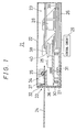
- Fig. 1 is a cross sectional side elevation view showing diagrammatically the construction of a
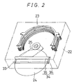
CD playback apparatus 21 according to one embodiment of the present invention. - Fig. 2 is a diagrammatic perspective view showing a
CD 24 being inserted in theCD playback apparatus 21 of Fig. 1. - Fig. 3 is a simplified perspective view showing the
CD 24 being played back in theCD playback apparatus 21 of Fig. 1. - Fig. 4 is a simplified perspective view showing a plurality of
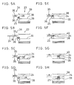
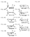
CDs 24 being stored in theCD playback apparatus 21 of Fig. 1. - Figs. 5A to 5H are simplified cross sectional side view showing a sequence of operations for inserting a
CD 24 in theCD playback apparatus 21 of the embodiment of Fig. 1. - Figs. 6A to 6F are simplified cross sectional side view showing a sequence of operations for ejecting a stored
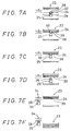
CD 24 from theCD playback apparatus 21 of Fig. 1. - Figs. 7A to 7F are simplified cross sectional side view showing a sequence of operations for transporting a
CD 24 into a accommodating position after playback in theCD playback apparatus 21 of Fig. 1. - Figs. 8A to 8I are simplified cross sectional side view showing a sequence of operations for playing back a
CD 24 in theCD playback apparatus 21 of Fig. 1. - Figs. 9A to 9L are simplified cross sectional side view showing a sequence of operations for changing
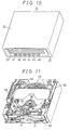
CDs 24 stored in astocker 23 for playback in theCD playback apparatus 21 of Fig. 1. - Fig. 10 is a perspective view of a
housing 22 of theCD playback apparatus 21 shown Fig. 1. - Fig. 11 is a perspective view showing a mechanism section with the
housing 22 of Fig. 10 removed. - Fig. 12 is a front view of the mechanism section of Fig. 11.
- Fig. 13 is a plan view of the mechanism section of Fig. 11.
- Fig. 14 is a right-side view of the mechanism section of Fig. 11.
- Fig. 15 is a left-side view of the mechanism section of Fig. 11.
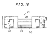
- Fig. 16 is a rear view of the mechanism section of Fig. 11.
- Fig. 17 is a perspective view of a
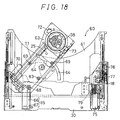
slide unit 60. - Fig. 18 is a plan view of the
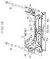
slide unit 60 of Fig. 17. - Fig. 19 is a perspective view of a
transport mechanism 34 in Fig. 1. - Fig. 20 is a simplified perspective view of
gear mechanisms - Fig. 21 is a perspective view of a
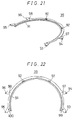
holder 39 constituting part of thestocker 23 shown in Fig: 1. - Fig. 22 is a plan view of the
holder 39 of Fig. 21. - Fig. 23 is a bottom view of the
holder 39 of Fig. 21. - Fig. 24A is a diagram showing the
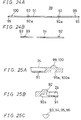
holder 39 of Fig. 21 as viewed from the front, and Fig. 24B is a diagram showing theholder 39 of Fig. 21 as viewed from the right-hand side. - Figs. 25A and 25B are diagrams showing, partly in cross section, the
holder 39 of Fig. 21, and Fig. 25C is a diagram showing, partly in cross section, theholder 39 of Fig. 21. - Fig. 26 is a perspective view of the
stocker 23 constructed by stacking theholders 39 of Fig. 21. - Fig. 27 is a plan view of the
stocker 23 of Fig. 26. - Fig. 28 is a front view of the
stocker 23 of Fig. 26. - Fig. 29 is a right-side view of the
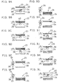
stocker 23 of Fig. 26. - Fig. 30A is a perspective view of a separating
slide plate 56 shown in Fig. 13, and Fig. 30B is a perspective view of a separatingslide plate 56 shown in Fig. 13. - Fig. 31 is a side view of the separating
slide plate 56a of Fig. 30A. - Fig. 32 is a simplified perspective view showing how the
holders 39 are separated using the separatingslide plates 56 of Figs. 30A and 30B. - Fig. 33 is an exploded perspective view showing the construction relating to a floating
mechanism 27 shown in Fig. 1. - Fig. 34 is a perspective view showing the construction relating to a
separating mechanism 28 shown in Fig. 1. - Figs. 35A and 35B are simplified plan views showing the construction relating to a
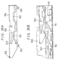
pressure lever 140 shown in Fig. 34, and Fig. 35C is a diagram showing, partly in cross section, the construction relating to thepressure lever 140 of Fig. 34. - Fig. 36A is a left-side view showing the construction of a PU lifting
slide plate 150 for moving aPU unit 25 of Fig. 1 up and down. - Fig. 36B is a left-side view showing the construction of a
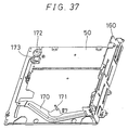
side plate 160 of achassis 50 shown in Fig. 11. - Fig. 37 is a perspective view of a basic mechanism section relating to the
chassis 50 shown in Fig. 11. - Fig. 38 is a left-side view showing the construction of a lifting
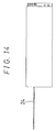
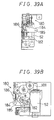
slide plate 54 shown in Fig. 36B. - Figs. 39A and 39B are a left-side view and a front view, respectively, of a
gear mechanism 180 for transmitting driving force from a liftingmotor 52 shown in Fig. 11. - Fig. 40 is a block diagram showing an electrical configuration for overall control of the
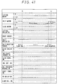
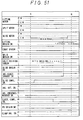
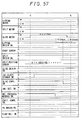
CD playback apparatus 21 of Fig. 1. - Fig. 41 is a timing chart illustrating the operation of a
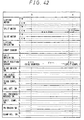
control circuit 29 of Fig. 40. - Fig. 42 is a timing chart illustrating the operation of the
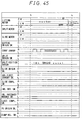
control circuit 29 of Fig. 40. - Fig. 43 is a timing chart illustrating the operation of the
control circuit 29 of Fig. 40. - Fig. 44 is a timing chart illustrating the operation of the
control circuit 29 of Fig. 40. - Fig. 45 is a timing chart illustrating the operation of the
control circuit 29 of Fig. 40. - Fig. 46 is a timing chart illustrating the operation of the
control circuit 29 of Fig. 40. - Fig. 47 is a timing chart illustrating the operation of the
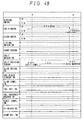
control circuit 29 of Fig. 40. - Fig. 48 is a timing chart illustrating the operation of the
control circuit 29 of Fig. 40. - Fig. 49 is a timing chart illustrating the operation of the
control circuit 29 of Fig. 40. - Fig. 50 is a timing chart illustrating the operation of the
control circuit 29 of Fig. 40. - Fig. 51 is a timing chart illustrating the operation of the
control circuit 29 of Fig. 40. - Fig. 52 is a timing chart illustrating the operation of the
control circuit 29 of Fig. 40. - Fig. 53 is a timing chart illustrating the operation of the
control circuit 29 of Fig. 40. - Fig. 54 is a timing chart illustrating the operation of the
control circuit 29 of Fig. 40. - Fig. 55 is a timing chart illustrating the operation of the
control circuit 29 of Fig. 40. - Fig. 56 is a timing chart illustrating the operation of the
control circuit 29 of Fig. 40. - Fig. 57 is a timing chart illustrating the operation of the
control circuit 29 of Fig. 40. - Fig. 58 is a timing chart illustrating the operation of the
control circuit 29 of Fig. 40. - Fig. 59 is a timing chart illustrating the operation of the
control circuit 29 of Fig. 40. - Fig. 60 is a timing chart illustrating the operation of the
control circuit 29 of Fig. 40. - Fig. 61 is a perspective view showing the construction of a stocker according to the prior art.
- Now referring to the drawings, preferred embodiments of the invention are described below.
- Fig. 1 is a diagram showing diagrammatically the overcall construction of an automotive
CD playback apparatus 21 according to one embodiment of the present invention. Ahousing 22 is constructed conforming to the standard size as vehicle-mounted equipment, known as 1DIN, that is, about 18 cm in width, about 5 cm in thickness, and about 17 cm in depth. Inside thehousing 22 is installed astocker 23 as a accommodating apparatus which is capable of accommodating up to six disk-shaped recording media orCDs 24. EachCD 24 has a diameter of about 12 cm and a thickness of about 1.2 mm, and its recorded information can be played back by aPU unit 25. The entire construction of thestocker 23 can be moved up and down by means of a movingmechanism 26 which serves as a selection mechanism. A floatingmechanism 27 supports thePU unit 25 in a mechanically floating condition with respect to other parts so that thePU unit 25 can be substantially isolated from external vibrations when theCD 24 mounted thereon is being played back. When one accommodating position is selected by the movingmechanism 26, thestocker 23 is separated between top and bottom by aseparating mechanism 28 to provide a space between the accommodating positions above and below the separating position. On one side of thehousing 22 are disposed an electronic circuit board, etc. containing acontrol circuit 29 for controlling the movements of the various parts. - The
PU unit 25 is mounted displaceably on aslide base 30 which is supported on the bottom of thehousing 22. Theslide base 30 can be held by means of the floatingmechanism 27 in such a manner as to float mechanically from the bottom of thehousing 22. Thecontrol circuit 29 performs control so that the floating by the floatingmechanism 27 is restrained by alock mechanism 31, except when playing back theCD 24, to prevent thePU unit 25 from swaying independently of other parts in thehousing 22. - An insertion/
ejection slot 33 is formed in afront panel 32 which serves as the operation panel of thehousing 22, and within thehousing 22, atransport mechanism 34 is provided adjacent to the insertion/ejection slot 33. Thetransport mechanism 34 includes atransport roller 35 and a supportingplate 36. TheCD 24 inserted or ejected through the insertion/ejection slot 33 is mounted on the supportingplate 36 and transported by the rotation of thetransport roller 35. When theCD 24 is being transported or played back inside thehousing 22, the insertion/ejection slot 33 is closed by ashutter mechanism 37 to prevent anotherCD 24 from being inserted accidentally. ThePU unit 25 includes a turn table 38 for holding and rotating theCD 24. - The
stocker 23, as will be described later, comprisesholders 39 as stocker members of identical construction stacked one on top of another. Theseparating mechanism 28 enters between designated stocker members to widen the gap therebetween, thus creating a space for thePU unit 25 to enter. Theseparating mechanism 28 works not only to separate thestocker 23 but also to displace theholders 39, the stocker members in the separated section of thestocker 23, further in the stacking direction, while also displacing the PU unit in the stacking direction. The turn table 38 is provided with achucking mechanism 40 for holding theCD 24. - Figs. 2, 3, and 4 are simplified schematic diagrams showing how the
CD 24 is inserted and played back in theCD playback apparatus 21 shown in Fig. 1 and how it is stored in thestocker 23. Fig. 2 shows theCD 24 being inserted through the insertion/ejection slot 33 of thehousing 22 and drawn into thehousing 22 by being sandwiched between thetransport roller 35 and supportingplate 36 of thetransport mechanism 34. When theCD 24 has been drawn into thehousing 22, theshutter mechanism 37 in Fig. 1 closes the insertion/ejection slot 33 to prevent anew CD 24 from being inserted. Once theCD 24 has been drawn into thehousing 22, thetransport roller 35 rotates in the reverse direction to push back theCD 24 until it is stopped by theshutter mechanism 37. This ensures correct positioning of theCD 24. - Fig. 3 shows the condition in which the
PU unit 25 moves upward from its standby position, mounts the thus positionedCD 24 on the turn table 38 by chucking, and moves into the separated space within thestocker 23. It is also possible to play back the insertedCD 24 by thePU unit 25 in this condition. - Fig. 4 shows the condition in which the
CD 24 mounted on the turn table 38 is being transferred from thePU unit 25, which has moved into the space within thestocker 23, to aholder 39 in thestocker 23. Theholder 39 as a stocker member, which is placed in a standby position below theCD 24 mounted and transported on the turn table 38, moves upward and removes theCD 24 from the turn table 38 by lifting the circumferential edge of theCD 24. On the other hand, when aCD 24 accommodated in thestocker 23 is to be transferred onto the turn table 38 of thePU unit 25 for ejection, theholder 39 holding theCD 24 moves downward and transfers theCD 24 held thereon onto the turn table 38. When accommodating theCD 24 into thestocker 23, thePU unit 25 from which theCD 24 has been transferred onto theholder 39 is moved out of the space in thestocker 23. When ejecting theCD 24, thePU unit 25 on which theCD 24 received from theholder 39 in thestocker 23 is mounted is withdrawn and theCD 24 is transferred onto thetransport mechanism 24. - Figs. 5A to 5H, Figs. 6A to 6F, Figs. 7A to 7F, Figs. 8A to 8I, and Figs. 9A to 9L are simplified schematic diagrams showing how the
CD 24 is inserted, ejected, accommodated, played back, and changed in theCD playback apparatus 21 of the present embodiment. Fig. 5A shows an insertion standby condition. In thetransport mechanism 34, thetransport roller 35 is lowered, ready to draw in theCD 24 when inserted. In thestocker 23, all the holders located below theholder 39 corresponding to the selected accommodating position are moved down to create a space therebetween, while all the holders located above the selectedholder 39 are moved up. TheCD 24 will be moved into the space created between the selectedholder 39 and the holders located above it. ThePU unit 25 is on standby in the standby position near the exit of thetransport mechanism 34. - Fig. 5B shows the condition in which the user of the
CD playback apparatus 21 has inserted oneCD 24 in the insertion/ejection slot 33 in Fig. 1. Thetransport roller 35 of thetransport mechanism 34 first draws the insertedCD 24 into thehousing 22, as shown in Fig. 5C, and then rotates in the reverse direction to position theCD 24, as shown in Fig. 5D. After theCD 24 has been drawn, as shown in Fig. 5C, theshutter mechanism 37 in Fig. 1 is closed. When theCD 24 is moved in the reverse direction, as shown in Fig. 5D, the rear edge of theCD 24 hits theshutter mechanism 37 in Fig. 1, and theCD 24 is thus positioned in place. - When the
CD 24 has been positioned as shown in Fig. 5 (D) , thePU unit 25 moves upward and receives theCD 24 by holding it on the turn table 38, as shown in Fig. 5E. Thechucking mechanism 40 provided on the turn table 38 is activated to clamp theCD 24 onto the turn table 38, as shown in Fig. 5F. Next, thePU unit 25 is moved in the direction of insertion, drawing theCD 24 out of thetransport mechanism 34 and transporting it into thestocker 23, as shown in Fig. 5G; then, in the PLAY condition as shown in Fig. 5H, thelock mechanism 31 in Fig. 1 is released, allowing thePU unit 25 to be supported on the floatingmechanism 27 in a mechanically floating fashion, and in this condition, information is played back from theCD 24. - Figs. 6A to 6F illustrate a sequence of operations for ejecting the
CD 24 from the playback condition shown in Fig. 5H. In the playback condition in Fig. 6A, thelock mechanism 31 in Fig. 1 is in an unlocked condition, but in Fig. 6B, thelock mechanism 31 in Fig. 1 is activated to restrain the floating condition provided by the floatingmechanism 27 in Fig. 1. In Fig. 6C, thePU unit 25 is moved away from the inside of thestocker 23 to the standby position near the exit of thetransport mechanism 34. In Fig. 6D, thechucking mechanism 40 is activated to unclamp theCD 24 from the turn table 38. In Fig. 6E, the PU unit moves down into the standby position, while at the same time, thetransport roller 35 of thetransport mechanism 34 lowers, thus holding theCD 24 between thetransport roller 35 and the supportingplate 36. In this way, theCD 24 is transferred from thePU unit 25 to thetransport mechanism 34. In Fig. 6F, thetransport roller 35 rotates to eject theCD 24. The ejection operation is stopped when theCD 24 is ejected partway through the insertion/ejection slot 33 in Fig. 1, thus allowing the user of theCD playback apparatus 21 to draw out theCD 24. - Figs. 7A to 7F are simplified schematic diagrams illustrating how the
CD 24 is stored in a accommodating position inside thestocker 23. The following explanation is given by assuming that the PLAY condition shown in Fig. 7A is the same as the PLAY condition shown in Fig. 5H. When theCD 24 inserted through the insertion/ejection slot 33 is to be stored in thestocker 23, the sequence of operations in Figs. 5A to 5H is immediately followed by the sequence of operations for accommodating theCD 24 without playing back theCD 24. In Fig. 7B, after thelock mechanism 31 in Fig. 1 is activated to restrain the floating condition, thePU unit 25 and theholder 39 for holding theCD 24 are moved upward. In Fig. 7C, theCD 24 clamped on the turn table 38 by thechucking mechanism 40 of thePU unit 25 is unclamped. In Fig. 7D, thePU unit 25 moves downward, disengaging theCD 24 from the turn table 38 and allowing it to rest on theholder 39. In Fig. 7E, thePU unit 25 moves to a position below thetransport mechanism 34, and in Fig. 7F, the separated section of thestocker 23 is moved down, thestocker 23 thus being reassembled into one unit. - Figs. 8A to 8I illustrate a sequence of operations for ejecting any one of the
CDs 24 accommodated in thestocker 23. When theholder 39 holding theCD 24 to be ejected is selected in the condition shown in Fig. 8A where thePU unit 25 is positioned below thetransport mechanism 34 and theentire stocker 23 is in the downward position, thestocker 23 is separated between the upper section, including the selectedholder 39, and the lower section located below the selectedholder 39, as shown in Fig. 8B. In Fig. 8C, thePU unit 25 moves into the thus created space in thestocker 23. In Fig. 8D, thePU unit 25 moves upward to hold on the turn table 38 theCD 24 to be ejected. In Fig. 8E, thechucking mechanism 40 is activated to clamp theCD 24 onto the turn table 38. In Fig. 8F, theholder 39 on which theCD 24 was held moves downward and theCD 24 is now mounted on the turn table 38. In Fig. 8G, thePU unit 25 including the turn table 38 with theCD 24 mounted thereon moves away from the space created in thestocker 23 to the standby position near the exit of thetransport mechanism 34. TheCD 24 is inserted in the space between the liftedtransport roller 35 and the supportingplate 36. In Fig. 8H, theCD 24 clamped on the turn table 38 by thechucking mechanism 40 is unclamped, and in Fig. 8I, thePU unit 25 is moved downward and, at the same time, thetransport roller 35 is lowered, thereby removing theCD 24 from the turn table 38 by holding theCD 24 between thetransport roller 35 and the supportingplate 36; thetransport roller 35 is then rotated to eject theCD 24. In Fig. 8I, when theCD 24 is removed from the insertion/ejection slot 33 by the user, the insertion standby condition is entered, allowing the insertion of anew CD 24. - Fig. 9A to 9L illustrate a sequence of disc change operations for changing one
CD 24 in the PLAY condition for anotherCD 24 stored in thestocker 23. The sequence of operations from Figs. 9A to 9F is the same as the sequence of operations shown in Figs. 7A to 7F. The sequence of operations from Figs. 9G to 9K is the same as the sequence of operations shown in Figs. 8A to 8E. In Fig. 9L, after thelock mechanism 31 in Fig. 1 is released and thePU unit 25 placed in a mechanically floating condition by the floatingmechanism 27, theholder 39 holding the selectedCD 24 is moved down so that theCD 24 can be played back. Since the locking by thelocking mechanism 39 is released, theCD 24 can be played back with the floatingmechanism 27 acting to substantially isolate thePU unit 25 from external vibrations. However, since there is a possibility that thePU unit 25 may be displaced relative to other parts because of the absorption of vibrations, it is preferable that thePU unit 25 with theCD 24 mounted thereon be moved to a position where theCD 24 does not hit surrounding parts. - Fig. 10 shows an external view of the
CD playback apparatus 21 of Fig. 1. In the vicinity of the insertion/ejection slot 33 of thefront panel 32, there are provided selector buttons 41 to 46 so that the accommodating position of aCD 24 stored in thestocker 23 can be specified. The accommodating positions are assignednumbers 1 to 6, for example, in sequence from bottom to top, and the corresponding number is specified using the appropriate one of the selector buttons 41 to 46. - Fig. 11 shows the construction of the internal mechanism of the
CD playback apparatus 21 of Fig. 1 with thehousing 22 removed. Figs. 12, 13, 14, 15, and 16 show the internal mechanism of Fig. 11 as viewed from the front, the top, the right-hand side, the left-hand side, and the rear, respectively. The entire construction of the internal mechanism is supported on achassis 50, the front side being the side where thefront panel 32 of thehousing 22 is disposed and the rear side being the side opposite from thefront panel 32. Theshutter mechanism 37 and thetransport mechanism 34 are arranged in the forward section of thechassis 50, while thestocker 23 is mounted in the rearward section. ThePU unit 25 is mounted movably in the backward and forward directions between the standby position shown in Fig. 13 and the insertion position in thestocker 23, with the center position of the turn table 38 always lying on thecenter line 51 of thechassis 50. Further, thePU unit 25 can be moved in swinging fashion with the turn table 38 at the swinging end, to move the turn table 38 to a position below thetransport mechanism 34. - Disposed at both widthwise ends of the
chassis 50 are the movingmechanism 26 for moving thestocker 23 up and down, theseparating mechanism 28 for separating thestocker 23, and the mechanism for operating thePU unit 25 and thelock mechanism 31, the mechanisms comprising slide plates or the like movable back and forth in reciprocating fashion. A liftingmotor 52 and aseparation motor 53 for driving the slide plates are mounted in the rear corners of thechassis 50. The liftingmotor 52 moves the liftingslide plates 54 back and forth along thechassis 50 and selects the accommodating position in thestocker 23 based on the number of stack levels counted by acount sensor 55. Based on the accommodating position selected by the liftingmotor 52, theseparation motor 53 drives the separatingslide plates 56 to separate thestocker 23. A separatingorigin point switch 57 and a liftingorigin point switch 58 for indicating the origin points of the separatingslide plates 56 and the liftingslide plates 54, respectively, are mounted at the front and rear ends of thechassis 50. The position of the slittingslide plates 56 is detected by aseparating position sensor 59. The separatingposition sensor 59 is a linearly variable resistor, and is used so as to indicate the position by an analog voltage. The sensor output is A/D converted and treated as a digital value. - In the present embodiment, the lifting
motor 52 is also used to drive thetransport roller 35. Thetransport roller 35 moves down to operate only when inserting or ejecting theCD 24, otherwise it is held in the lifted position; therefore, to simplify the mechanism, thetransport roller 35 is driven by the liftingmotor 52 at all times. When it becomes necessary to move thestocker 23 up or down, a clutch mechanism is operated to couple the driving force to the liftingslide plates 54. The clutch mechanism in the present embodiment allows the driving force of the liftingmotor 52 to be coupled to the liftingslide plates 54 when the separatingslide plates 56 are at their origin point. When the separatingslide plates 56 have moved away from their origin point, the clutch mechanism described later disengages the driving force of the liftingmotor 52 from the liftingslide plates 54. - Fig. 17 shows the construction of a
slide unit 60, mounted on theslide base 30, for moving thePU unit 25. Fig. 18 is a perspective plan view showing theslide unit 60 moved rearward relative to theslide base 30. Theslide unit 60 substantially comprises aslide plate 61 and aswivel plate 62. Theslide plate 61 is movable backward and forward relative to theslide base 30. Theswivel plate 62 can be swivelled about aswivel axis 63 provided at its base end in such a manner as to cause thePU unit 25 at the tip to describe an arc relative to theslide plate 61. An arc-shapedguide slot 64 for guiding the swivelling motion of theswivel plate 62 is formed in theslide plate 61. An L-shapedguide slot 65 consisting of alongitudinal slot 66 and alateral slot 67 is formed in theslide base 30. Theswivel axis 63 has aprotrusion 68 which engages in the L-shapedguide slot 65 of theslide base 30; when theprotrusion 68 is engaged in thelateral slot 67 of the L-shapedguide slot 65, aprotrusion 69 provided on theswivel plate 62 engages in the arc-shapedguide slot 64 of theslide plate 61, allowing theswivel plate 62 to swivel. When theprotrusion 68 on theswivel plate 62 becomes engaged in thelongitudinal slot 66 of the L-shapedguide slot 65, further swivelling motion of theswivel plate 62 is prevented, allowing only forward and backward movements with theprotrusion 68 engaged in thelongitudinal slot 66. - The
PU unit 25 is moved on theswivel plate 62 by means of afeed screw shaft 71 which is driven for rotation by afeed motor 70. The positioning of thePU unit 25 at the origin point on the turn table 38 is detected by a PUorigin point switch 72. In the case of a conventional PU unit, when the PU unit has reached the origin point, no further driving by thefeed motor 70 is not performed. In the present embodiment, on the other hand, thePU unit 25 is not stopped mechanically at the origin point, but thefeed motor 70 is further driven, thereby enabling the clamping by thechucking mechanism 40 to be released. The clamp released condition is detected by aclamp release switch 73. The turn table 38 is directly driven for rotation by aspindle motor 74. - The
slide unit 60 is moved relative to theslide base 30 by means of aslide motor 75. Theslide motor 75 is mounted on theslide base 30, and the moving position of theslide plate 61 is detected by a slideorigin point switch 76, aslide completion switch 77, and an insertion/ejection standby switch 78. In theslide unit 60, a gear mechanism for transmitting the driving force of theslide motor 75 to theslide plate 61 includes aslip mechanism 79 for preventing the transmission of excessive driving force. The forward movement of theslide plate 61 is limited bypins 61a striking against prescribed portions of thetransport mechanism 34. - Fig. 19 shows the construction of the
transport mechanism 34 and an open/close mechanism including theshutter mechanism 37. The driving forces of the liftingmotor 52 and splittingmotor 53 mounted in the rearward section are transmitted to spur gears 80 and 81, respectively. Since thetransport roller 35 in thetransport mechanism 34 is driven by the liftingmotor 52 mounted in the rearward section, as previously described, adrive shaft 82 with the spur gear 80 clamped to its base end is provided in extending fashion and coupled at its other end to agear mechanism 83. Likewise, the driving force of the splittingmotor 53 mounted in the rearward section is transmitted via adrive shaft 84 with the spur gear 81 clamped to its base end, to rotate alink shaft 85 linking between both sides and thus drive both separatingslide plates 56 equally in the forward and backward directions viagear mechanisms link shaft 85. - The
shutter mechanism 37 in the open/close mechanism includes an open/close slide plate 88a, ashutter sliding member 88b, and ashutter member 88c. The open/close mechanism itself further includes open/close pins 89a in conjunction with which an open/close stopper 89b and apin sliding plate 89c are provided. The open/close pins 89a as a pair are arranged at both widthwise ends, spaced apart by a distance smaller than the diameter of theCD 24 to prevent anotherCD 24 from being inserted. When inserting thefirst CD 24, or when ejecting aCD 24, the open/close pins 89a are retracted out of the moving range of theCD 24 by the insertion or ejecting force of theCD 24 to allow the insertion and ejection of theCD 24. When preventing double insertion, the open/close pins 89a are restrained by the open/close stopper 89b and do not retract when being hit by aCD 24, thus preventing the insertion of theCD 24. Theshutter member 88c, as earlier described, is used when positioning the insertedCD 24 in place by rotating thetransport roller 35 in the reverse direction. - Further, an
insertion detection switch 90a, an insertion presence/absence switch 90b, aninsertion completion switch 90c, and anejection completion switch 90d are also provided in connection with the insertion and ejection of theCD 24. - The linear movement of the
slide unit 60 is performed via thegear mechanisms slip mechanism 79, to both sides of theslide base 30 by means of thelink shaft 85. Since both sides are driven simultaneously and equally, a smooth movement can be accomplished. - Fig. 20 shows a simplified schematic of the
gear mechanisms bevel gear 83a forming a part of thegear mechanism 83 for driving thetransport roller 35 is provided at the end of thedrive shaft 82, and transmits the driving force from the liftingmotor 52 to abevel gear 83b and aspur gear 83c. Abevel gear 84a is provided at the end of thedrive shaft 84, and transmits the driving force from the splittingmotor 53 to abevel gear 84b and aspur gear 84c. Thelink shaft 85 is provided withspur gears spur gear 85c at its left end. The driving force from the splittingmotor 53 is transmitted from thespur gear 84c to thespur gear 85a via aspur gear 86b mounted on ashaft 86a of thegear mechanism 86. - The
spur gear 86b is not fixed to theshaft 86a, but is rotatable freely around theshaft 86a. Aspur gear 86c and apinion gear 86d are mounted at both ends of theshaft 86a of thegear mechanism 86. Thegear mechanism 87 at the left side comprises aspur gear 87b rotatable freely around ashaft 87a and aspur gear 87c andpinion gear 87d mounted at both ends of theshaft 87a, and has the same construction as thegear mechanism 86 at the right side. - When the driving force is transmitted to the
spur gear 85a, thelink shaft 85 rotates and the driving force is transmitted to the spur gears 86c and 87c via the spur gears 85b and 85c, respectively. This driving force causes the pinion gears 86d and 87d to rotate, thus driving the racks of the separatingslide plates gear mechanism 87 at the left side, the driving force transmitted from the liftingmotor 52 via thedrive shaft 82 is transmitted via thespur gear 87b to the drive mechanism for thetransport roller 35. - Figs. 21, 22, 23, 24A, and 24B show the shape of the
holder 39. Fig. 21 is a perspective view, Fig. 22 is a plan view, Fig. 23 is a bottom view, Fig. 24A is a front view, and Fig. 24B is a right-side view. Theholder 39 is substantially semicircular in shape. ACD mounting portion 91 for mounting aCD 24 is formed along the inner circumference of theholder 39. Theholder 39 is designed so as to hold the circumference of theCD 24 along a length greater than the semicircular length so that theCD 24 can be held by just placing theCD 24 in a horizontal position onto theCD mounting portion 91. Aretention projection 92 for holding theCD 24 mounted on theCD mounting portion 91 in place is formed at the rear end of theholder 39. Splittingprojections holder 39 by the splittingslide plates 56, as will be described later, are formed on both sides of theholder 39. Further, a pair of insertion holes 97 and 98 are formed at both widthwise sides of theholder 39. Positionaldisplacement prevention projections holder 39. - Fig. 25A shows the cross sectional structure including the positional
displacement prevention projections retention pawl 92, and Fig. 25c shows the end face shape of the splittingprojections displacement prevention projection 99 is protruding from the surface of theholder 39. The depth of theCD mounting portion 91, measured relative to the surface of theholder 39, is made larger than the thickness of theCD 24 so that the surface of theCD 24, when mounted on theCD mounting portion 91, does not protrude above theCD mounting portion 91. Recessedportions displacement prevention projections holders 39 are stacked one on top of the other, the recessedportions upper holder 39 engage onto the positionaldisplacement prevention projections lower holder 39, preventing positional displacement while, at the same time, making it possible to stack the holders close together without leaving gaps between them. - As shown in Fig. 25B, the
retention pawl 92 is formed at a position slightly spaced away from theCD 24 mounted on theCD mounting portion 91. When theCD 24 is pushed in the direction of insertion, the surface of theCD 24 touches theretention pawl 92 by which theCD 24 is held in place so as not to come off theCD mounting portion 91. More specifically, theretention pawl 92 has such a shape that covers a portion of the surface of theCD 24 only when the outer edge of theCD 24 is pressed against the holder wall surface. - As shown in Fig. 25C, the end face shape of the splitting
projections slide plate 56 to easily enter the space below and above the splittingprojections holders 39 and widen the gap between them. - Figs. 26, 27, 28, and 29 show the
stocker 23 constructed with theholders 39 stacked one on top of another. Fig. 26 is a perspective view, Fig. 27 is a plan view, Fig. 28 is a front view, and Fig. 29 is a right-side view. - The
stocker 23 includes abottom plate 101 which is lifted up and down by the liftingslide plates 54, a pair of lift guides 102 and 103 formed protruding upward from thebase plate 101, the sixholders 39 through the insertion holes 97 and 98 of which are inserted the lift guides 102 and 103, and atop plate 104. Thetop plate 104, except for the center cut-out 105 thereof, is formed in a substantially rectangular shape so that it can hold down the upper surface of theCD 24 mounted on theuppermost holder 39. Splittingprojections 106 to 109 corresponding to the separatingprojections 93 to 96 of theholders 39 are formed at the four corners of the rectangle. - The
top plate 104 is also provided withinsertion holes displacement prevention projections 99 of theuppermost holder 39. In the present embodiment, theholders 39 of identical construction can be used for accommodating a plurality ofCDs 24.Pins slide plates 54 for lifting operation are formed on both sides of thebottom plate 101. -
Spring retainers 118 are provided on both sides of thetop plate 104. A thin,long coil spring 119 is connected to eachspring retainer 118, and the end of eachcoil spring 119 is hooked onto the end of theother coil spring 119 for connection at the center of thebottom plate 101. Since the coil springs 119 are long, the spring force urging thestocker 23 in the closing direction can be made substantially the same when the overall length of the springs is expanded by separating thestocker 23 as when the overall length is contracted by closing thestocker 23. Pulleys are provided where the coil springs 119 bend to ensure smooth changes in direction. - Figs. 30A, 30B, and 31 show the shape of the separating
slide plates 56 that can separate thestocker 23 at an arbitrary position. Figs. 30A and 30B show perspective views, and Fig. 31 shows a side view. Fig. 30A shows the right-sideseparating slide plate 56a, and Fig. 30B shows the left-sideseparating slide plate 56b. Two pairs of upper andlower cams slide plate 56, one upper/lower cam pair in the forward section and the other pair in the rearward section of the plate. The separatingprojections 93 to 96 on theholder 39 at the accommodating position at which thestocker 23 is separated move upward along the slopes of theupper cams 120. The holder underneath theholder 39 at which thestocker 23 is separated is prevented by thelower cams 121 from moving upward. The separatingprojections 93 to 96 moving upward along the slopes of theupper cams 120 are separated byseparators 122 between theholder 39 at the accommodating position and theholder 39 above it. When theuppermost holder 39 is selected, the separatingprojections 106 to 109 on thetop plate 104 are separated by theseparators 122. Thelower holder 39 is further pressed downward by the spring force of pressingportions 123. The forward and backward movements of the separatingslide plates 56 are accomplished by driving theracks 124, each provided in the forward upper section of each separatingslide plate 56, by means of the pinion gears 86d and 87d in thegear mechanisms - A
spring retainer 125 for interlocking with the lifting mechanism of theslide unit 60 shown in Fig. 17 is provided on the upper side of each separatingslide plate 56, and apin 126 is provided in protruding fashion on one side of the plate. Further, as will be described later in connection with Figs. 35A and 35B, apressure release cam 127 is provided at the front end of the separatingside plate 56a in connection with the mechanism for pressing theCD 24 in the lower separated section of thestocker 23 to prevent it from coming off. - In Fig. 31, the relationships between the separating
projections holder 39 located above the selectedholder 39, the selectedholder 39, and theholder 39 located below the selectedholder 39, respectively. When the selectedholder 39 is theuppermost holder 39, the member located above it is thetop plate 104. When the selectedholder 39 is thelowermost holder 39, the member located below it is thebottom plate 101. The last numbers "1", "2", "3", and "4" correspond to the separated conditions of thestocker 23. - Referring to Figs. 5 to 9, "1" indicates the
stocker 23 in the closed condition corresponding to Figs. 7F, 8A, 9F, and 9G. The number "2" indicates the separated condition corresponding to Figs. 7B to 7E, 8B to 8E, 9B to 9E, and 9H to 9K. The number "3" indicates the condition corresponding to Figs. 5H, 6A, 7A, 9A, and 9L. The number "4" indicates the condition corresponding to Figs. 5A to 5G, 6B to 6F, and 8F to 8I. - Fig. 32 shows the
upper cams 120 andlower cams 121 displacing the separatingprojections 93 to 96 to separate theholders 39. Using the separatingslide plates 56 shown here, the separated conditions shown in Figs. 5 to 9 can be accomplished. - Fig. 33 shows a simplified schematic of the floating
mechanism 27 for theslide base 30. The floatingmechanism 27 includesdampers 130 mounted on thechassis 50, pins 131 inserted in thedampers 130 from theslide base 30 side, and springs 132 disposed outwardly of thedampers 130 and pins 131.Lock shafts 133 and alock piece 134 are also provided on theslide base 30 in such a manner as to protrude toward thechassis 50. A lockingnotch 135 is formed in thelock piece 134. Thelock mechanism 31 mounted on thechassis 50 restrains thelock shafts 133 to prevent relative motion in a plane perpendicular to the thickness, i.e., in the horizontal plane, and restrains the vertical motion of thePU unit 25 by using thelocking notch 135 of thelock piece 134. - A
pressure lever 140, which is provided adjacent to thelock mechanism 31, is used to press theCD 24 in the lower separated section of thestocker 23. Thepressure lever 140 is urged by aspring 141 and presses the upper surface and edge face of theCD 24. When thestocker 23 is not separated, the pressing force is released. The height at which to separate thestocker 23 is fixed, and the position of theholder 39 at which to separate thestocker 23 is determined by the upward/downward movement of the entire construction of thestocker 23. Accordingly, thepressure lever 140 can always press theuppermost CD 24 in the lower separated section of thestocker 23. - Fig. 34 shows the arrangement of the essential parts constituting the
separating mechanism 28 shown in Fig. 1. On both sides of thechassis 50 are arranged the separatingslide plates 56 which move back and forth in interlocking fashion. The right-side separating slide plate is designated by 56a and the left-side plate by 56b, and they are collectively designated byreference numeral 56. In connection with the separatingslide plates 56, thepressure lever 140 is disposed in the forward section of thechassis 50. Thepressure lever 140 is urged by thespring 141 in such a manner as to press the lower separated section of thestocker 23 from the front side to prevent theCDs 24 accommodated therein from coming off the holders. When the separatingslide plates 56 are moved to the forward end position and thestocker 23 is restored to the unsplit condition, the pressing force being applied on thestocker 23 by thepressure lever 140 is released. - Figs. 35A, 35B, and 35C show the construction relating to the action of the
pressure lever 140. When the separatingslide plate 56a is moved rearward and thepressure release cam 127 is not in contact, as shown in Fig. 35A, thepressure lever 140 is in the pressing condition. When the separatingslide plate 56a is moved back to its origin point, as shown in Fig. 35B, thepressure release cam 127 comes into action, and thepressure lever 140 is released. The action to release thepressure lever 140 is performed via arelease lever 142. When apin 143 at one end of therelease lever 142 is driven so as to move therelease lever 142 to the left by being guided by thepressure release cam 127, apin 144 at the other end applies such an angular displacement to thepressure lever 140 as to release the pressing force. - Fig. 35C shows the cross sectional shape of the
pressure lever 140 taken along cutting line C-C in Fig. 35A. An uppersurface pressing portion 145 and an edgeface pressing portion 146 are formed on the portions of thepressure lever 140 that contact the circumference of theCD 24. - Figs. 36A and 36B show the construction relating to a PU lifting
slide plate 150 for moving theslide base 30 up and down in interlocking fashion with the separatingslide plate 56. Fig. 36A shows the PU liftingslide plate 150 itself, and Fig. 36B shows the liftingslide plate 150 mounted on thechassis 50 as viewed from the left side thereof. - As shown in Fig. 36A,
PU lifting slots 151 for moving theslide base 30 up and down are formed in the PU liftingslide plate 150. The PU liftingslide plate 150 moves backward and forward by being guided bypins 152. Aninterlocking slot 153 engages on thepin 126 of the separatingslide plate 56 and, when the separatingslide plate 56 moves backward more than a certain distance, causes the PU liftingslide plate 150 to move backward in interlocking fashion, causing therack 154 formed on the upper side to engage with thepinion gear slide plate 150 to move further backward. The PU liftingslide plate 150 is also provided with aspring retainer 155 on which one end of a coil spring, whose other end is supported on thespring retainer 125 of the separatingslide plate 56, is hooked. - As shown in Fig. 36B, the PU lifting
slide plate 150 is mounted on aside plate 160 of thechassis 50.Slide slots 161 serving as cams are formed in theside plate 160, and thepins 152 of the PU liftingslide plate 150 engage in the slots which thus guide the backward/forward movement of the PU liftingslide plate 150. Mounted below the PU liftingslide plate 150 is the liftingslide plate 54. - The PU lifting
slide plate 150 can be made integral with the separatingslide plate 56. In that case, thePU lifting slots 151 are formed in the separatingslide plate 56. By providing these slide plates separately as in the present embodiment, the length necessary in the longitudinal direction can be reduced. - Fig. 37 shows the basic drive mechanism for the lifting
slide plates 54, mounted on thechassis 50, and Fig. 38 shows the construction of the liftingslide plate 54 itself. The liftingslide plates 54 on both sides are mechanically linked together by an interlinkinglever 170 located in the forward section of thechassis 50, and move in opposite directions to each other in such a manner that when one moves in the forward direction, the other moves in the backward direction. The interlinkinglever 170 is mounted swingably about asupport shaft 171 at the center. The left-sidelifting slide plate 54 is moved backward and forward by the driving force transmitted from the liftingmotor 52 to apinion gear 173 via abevel gear 172. - As shown in Fig. 38, step-
like slots 174 are formed in each liftingslide plate 54, and are engaged with thepins bottom plate 101 of thestocker 23. The step-like slots 174 work as cams and move the entire construction of thestocker 23 up and down. When selecting aparticular holder 39, thestocker 23 is moved up or down so that the position between theholders 39 at which thestocker 23 is to be separated is brought to the same height as the height of the tip of the separatingslide plate 56. In the present embodiment, theholder 39 located above the separating position is selected, but it is equally possible to make the construction so that theholder 39 below the separating position is selected. - Fig. 39A and 39B show the construction of a
gear mechanism 180 interposed between thebevel gear 172 shown in Fig. 37 and the liftingmotor 52. Fig. 39A is a left-side view, and Fig. 39B is a front view. The driving force is transmitted to thegear mechanism 180 via aworm gear 181 mounted to the output shaft of the liftingmotor 52. Inside thegear mechanism 180 is provided aplanetary gear 182 which engages or disengages the driving force transmission to a bevel gear 183. When apin 185 at the end of aclutch lever 184 is pressed by the tip of the separatingslide plate 56b, theplanetary gear 182 is so displaced as to be disengaged from the bevel gear 183. As long as thepin 185 is not pressed by the tip of the separatingslide plate 56b, aspring 186 keeps theplanetary gear 182 in engagement with the bevel gear 183 so that the driving force is transmitted via the bevel gear 183 to thebevel gear 172 to drive the liftingslide plate 54. - The movement of the separating
slide plate 56b that stops the driving of the liftingslide plate 54 corresponds to the condition indicated by the reference characters 93a4, 93b4, 93c4, 94a4, 94b4, and 94c4 in Fig. 31, in which condition thestocker 23 is separated and the selectedholder 39 is positioned downward of the turn table 38. In this condition, only the PU liftingslide plate 150 is driven by the driving force of the splittingmotor 54 to move thePU unit 25 up and down. - Fig. 40 shows an electrical configuration for controlling the various parts of the
CD playback apparatus 21 by thecontrol circuit 29 in Fig. 1. Thecontrol circuit 29 includes a microcomputer or the like which performs various operations in accordance with a preset program. The kind of operation to be performed is specified in accordance with an instruction from aninput switch 190 which includes the selector buttons 41 to 46 provided on thefront panel 32. - Figs. 41 to 60 show the control operations performed by the
control circuit 29 of Fig. 40. Each motor can switch the direction of its rotation between clockwise direction (CW) and counterclockwise direction (CCW). The output value of theseparating position sensor 59 is an analog-to-digital converted value and expressed as a hexadecimal number with a suffix "h". Further, "const.", "inc.", and "dec." indicate that the value is constant, increases, or decreases, respectively. - Fig. 41 shows the control timing for the operation performed from the time that the
slide base 30, including thePU unit 25, is floated from thechassis 50 by means of the floatingmechanism 27, until the time that theCD 24 is returned to theholder 39 in thestocker 23. At operation start point S, theholder 39 temporarily moved downward, as shown in Fig. 9A, is moved upward by driving the separatingslide plates 56 by rotating the splittingmotor 53 in the counterclockwise direction (CCW); theholder 39 pressed downward by theseparators 122 is now moved upward and the floating condition is restored by releasing the lock applied by thelock mechanism 31. Fig. 42 shows a sequence of operations by which theCD 24 clamped by thechucking mechanism 40 is unclamped and theslide unit 60 is moved downward to disengage theCD 24 from the turn table 38. Fig. 43 shows a control sequence for the operation performed to withdraw theslide unit 60 from the inside of thestocker 23 and retract it into the standby position. Fig. 44 shows a sequence of operations by which thePU unit 25 is retracted outside thestocker 23 and the space created by separating thestocker 23 is closed by the movement of the separatingslide plates 56, thus putting thestocker 23 in the unsplit condition to end the separated condition. Fig. 45 shows a sequence of operations by which the entire construction of thestocker 23 is moved up and down by the liftingslide plates 54. The liftingslide plates 54 are moved to select one of the accommodating positions in thestocker 23. When the selected accommodating position is detected using the output of thecounter sensor 55, the liftingmotor 52 is stopped. With the control sequence illustrated in Figs. 41 to 45 above, the sequence of operations from Fig. 7A to 7F or Fig. 9A to 9F can be performed. - Fig. 46 shows the control operations when separating the
stocker 23 by the slittingslide plates 56. Fig. 47 shows the operation for inserting thePU unit 25 in the space created by separating thestocker 23. Fig. 48 shows the operation for moving upward the turn table 38 of thePU unit 25 inserted in thestocker 23 and for mounting theCD 24 on the turn table 38. Fig. 49 shows the control of operations by which theCD 24 is clamped onto the turn table 38 by activating thechucking mechanism 40 and the locking by thelock mechanism 31 is released to allow thePU unit 25, etc. on theslide base 30 to be floated by the floatingmechanism 27. With the control sequence illustrated in Figs. 46 to 49, the sequence of operations from Figs. 9G to 9L can be performed. - Fig. 50 shows the control of operations by which, with the
CD 24 clamped on the turn table 38 in thestocker 23, theholder 39 on which theCD 24 was accommodated is moved downward. Fig. 51 shows the operation for transporting the CD clamped on the turn table 38 to the standby position by using thePU unit 25. Fig. 52 shows the control of operations by which, with thePU unit 25 positioned in the standby position, theCD 24 clamped on the turn table 38 by thechucking mechanism 40 is unclamped, and theslide unit 60 is moved down while, at the same time, thetransport roller 35 is lowered to hold theCD 24 in the transport mechanism 34-and the turn table 38 is retracted below the transport path of theCD 24. Fig. 53 shows the control of operations for ejecting theCD 24 outside by driving thetransport roller 35. The control sequence illustrated in Figs. 50 to 53 corresponds to the sequence of operations shown in Figs. 6A to 6F. - Fig. 54 shows the control of operations by which the
CD 24 inserted through the insertion/ejection slot 33 is drawn inside by thetransport roller 35. Fig. 55 shows the control of operations by which thetransport roller 35 is driven in the reverse direction to position theCD 24 into the standby position. Fig. 56 shows the control of operations by which thePU unit 25 is moved upward to mount the thus positionedCD 24 onto the turn table 38. Fig. 57 shows the control of operations by which theCD 24 clamped on the turn table 38 by thechucking mechanism 40 is transported into the space in thestocker 23 by moving thePU unit 25. With the control sequence illustrated in Figs. 54 to 57 above, the sequence of operations in Figs. 5A to 5G can be performed. - Fig. 58 shows the control of operations by which the
slide base 30 is locked by thelock mechanism 31 and the turn table 38 of thePU unit 25 is moved upward. Figs. 59 and 60 show the operations for clamping theCD 24 onto the turn table 38 and for unclamping theCD 24, respectively. As previously described, the clamping of theCD 24 by theclamp mechanism 40 is performed using thefeed motor 70 which moves thePU unit 25 into the chucking position. To achieve this, the PUorigin point switch 72 and theclamp release switch 73 are used as inputs in the control of thechucking mechanism 40. - While the above embodiment has been described dealing with the
CD 24 which is a disk-shaped recording medium, the present invention is equally applicable to other disk-shaped recording media such as DVDs. The invention can also be applied to MDs and like recording media housed in cassettes or cartridges. Further, since theCD 24 is handled in a substantially horizontal position, the accommodating and transport mechanisms can be simplified, but the mechanisms can be adapted to handle theCD 24 in other positions. - As the recording media, not only the playback-only
CD 24 but information recordable media such as CD-R or CD-RW can also be used. Such writable recording media can be used as information recording media, for example, for personal computers. By applying the present invention, a playback apparatus or a playback/recording apparatus capable of accommodating many recording media, whether it is internal or external to a personal computer or the like, can be made compact in construction, and yet the recording media can be inserted or ejected one at a time. - The invention may be embodied in other specific forms without departing from the spirit or essential characteristics thereof. The present embodiments are therefore to be considered in all respects as illustrative and not restrictive, the scope of the invention being indicated by the appended claims rather than by the foregoing description and all changes which come within the meaning and the range of equivalency of the claims are therefore intended to be embraced therein.
Claims (12)
- A separating apparatus for a recording media accommodating apparatus having a plurality of stacked holders (39) rendering accommodating positions for recording media (24) to be inserted or ejected to or from the accommodating apparatus one at a time;
the separating apparatus comprising:separating members (56) which enter between holders (39) and thereby widen a gap between the holders (39) for creating a space therebetween;a selection mechanism (54) for moving the plurality of holders (39) in its entirety along the stacking direction, and for selecting the position at which the separating members (56) enter between the holders (39); anda separating mechanism (53, 86, 87) for causing the separating members (56) to enter between the holders (39) and thereby separating the holders (39) such that a playback mechanism (25) for playing back and/or for recording information can move into the space created by the separation of the holders (39) and transfer a recording media (24) to or from a holder (39). - The apparatus of claim 2, wherein the separating members (56) are provided on each side of the holder (39) assembly as a pair.
- The apparatus of claim 1 or 2, wherein the recording media (24) are of a disk-like shape, and the holders (39) are substantially semicircular in shape, each holder being constructed to accommodate a recording medium (24) in a substantially horizontal position, and having an opening facing the direction of the movement of the playback mechanism (25) and separating guide portions (93, 94, 95, 96) with which the separating members (56) engage to separate the accommodating apparatus.
- The apparatus of claim 2 or 3, wherein the separating mechanism (53, 86 ,87) is provided with a driving source (53) for driving the pair of separating members (56) so as to simultaneously enter between the holders (39).
- The apparatus of claim 4, wherein the separating mechanism (53, 86, 87) is further provided with transmission mechanisms (86, 87) of identical construction for transmitting driving force from the driving source (53) to the pair of separating members (56).
- The apparatus of one of the claims 1 to 5, further comprising:a spring (119) for urging the plurality of holders (39) toward one side of the stacking direction is provided.
- The apparatus of one of the claims 1 to 6, wherein the separating members (56) are provided with a pressing portion (123) for elastically pressing a portion contacting one of the holders (39) to be separated, of those portions which come into contact with the holders (39) when the separating members enter between the holders (39) to widen the gap therebetween.
- The apparatus of one of the claims 1 to 7, wherein the separating mechanism (53, 86, 87) moves the separating members (56) so that one of the holders (39) located in the separated space is displaced in the stacking direction after the playback mechanism (25) has entered the space.
- The apparatus of one of the claims 1 to 8, wherein the separating members (56) have cam faces (120, 121) for displacing the one and the other holder (39) in the space in the stacking direction as the separating members (56) are moved in the direction of insertion.
- The apparatus of one of the claims 1 tom 9, wherein the separating members (56) have cams (150) for displacing the playback mechanism (25) in the stacking direction.
- The apparatus of one of the claims 1 to 9, wherein the separating mechanism (53, 86, 87) is provided with a cam member (150) for displacing the playback mechanism (25) in the stacking direction in interlocking fashion with the holder (39) separation action performed by the separating members (56).
- A recording media accommodating apparatus having a plurality of accommodating positions arranged along a recording media (24) thickness direction for individually accommodating substantially disk-shaped recording media (24), the apparatus comprising:a housing (22) provided with an insertion/ejection slot (33) through which the recording media (24) are inserted or ejected one at a time;a separating apparatus according to one or more of the preceding claims,a plurality of holders (39) in the housing (22) disposed at the respective accommodating positions, separable by said separating apparatus in the thickness direction at an arbitrary accommodating position, each holder being capable of holding one recording medium (24); anda playback mechanism (25) for playing back information recorded on the recording media (24), the playback mechanism (25) being capable of moving into a space created by the holder (39) separation and transferring the recording media (24) to and from the holders (39) and also capable of moving to a position near the insertion/ejection slot (33) and transferring the recording media (24) to and from the insertion/ejection slot (33).
Applications Claiming Priority (3)
| Application Number | Priority Date | Filing Date | Title |
|---|---|---|---|
| JP21616198A JP3621264B2 (en) | 1998-07-30 | 1998-07-30 | Storage device for recording medium |
| JP21615798A JP3608953B2 (en) | 1998-07-30 | 1998-07-30 | Stocker dividing device for storing recording medium |
| EP99114273A EP0977197B1 (en) | 1998-07-30 | 1999-07-29 | Storage device for recording media |
Related Parent Applications (2)
| Application Number | Title | Priority Date | Filing Date |
|---|---|---|---|
| EP99114273.8 Division | 1999-07-29 | ||
| EP99114273A Division EP0977197B1 (en) | 1998-07-30 | 1999-07-29 | Storage device for recording media |
Publications (2)
| Publication Number | Publication Date |
|---|---|
| EP1650754A1 true EP1650754A1 (en) | 2006-04-26 |
| EP1650754B1 EP1650754B1 (en) | 2010-09-15 |
Family
ID=26521265
Family Applications (2)
| Application Number | Title | Priority Date | Filing Date |
|---|---|---|---|
| EP99114273A Expired - Lifetime EP0977197B1 (en) | 1998-07-30 | 1999-07-29 | Storage device for recording media |
| EP06001770A Expired - Lifetime EP1650754B1 (en) | 1998-07-30 | 1999-07-29 | Storage device for recording media |
Family Applications Before (1)
| Application Number | Title | Priority Date | Filing Date |
|---|---|---|---|
| EP99114273A Expired - Lifetime EP0977197B1 (en) | 1998-07-30 | 1999-07-29 | Storage device for recording media |
Country Status (4)
| Country | Link |
|---|---|
| US (1) | US6370105B1 (en) |
| EP (2) | EP0977197B1 (en) |
| CN (1) | CN100346417C (en) |
| DE (2) | DE69934456T2 (en) |
Cited By (1)
| Publication number | Priority date | Publication date | Assignee | Title |
|---|---|---|---|---|
| US7565666B2 (en) | 2004-05-19 | 2009-07-21 | Fujitsu Ten Limited | Disk autochanger |
Families Citing this family (11)
| Publication number | Priority date | Publication date | Assignee | Title |
|---|---|---|---|---|
| US6751181B1 (en) * | 1999-09-28 | 2004-06-15 | Sony Corporation | Recording and/or reproducing device for disks |
| JP3906114B2 (en) * | 2002-06-10 | 2007-04-18 | 富士通テン株式会社 | Disc player |
| JP4083059B2 (en) * | 2003-03-31 | 2008-04-30 | クラリオン株式会社 | Disk transport device and disk device |
| WO2005093743A1 (en) * | 2004-03-25 | 2005-10-06 | Pioneer Corporation | Recording medium reproducer |
| WO2005096292A1 (en) * | 2004-03-31 | 2005-10-13 | Clarion Co., Ltd. | Disk clamp device |
| JP4420717B2 (en) * | 2004-03-31 | 2010-02-24 | クラリオン株式会社 | Drive unit transfer device and disk device |
| WO2005096297A1 (en) * | 2004-03-31 | 2005-10-13 | Clarion Co., Ltd. | Floating lock device |
| JP2006202435A (en) * | 2005-01-21 | 2006-08-03 | Fujitsu Ten Ltd | Disk changer |
| JP4311567B2 (en) * | 2005-03-25 | 2009-08-12 | アルパイン株式会社 | Disk storage type disk device |
| CN101346765B (en) * | 2006-01-20 | 2012-07-18 | 三菱电机株式会社 | Disk device |
| JP2008097731A (en) * | 2006-10-12 | 2008-04-24 | Sony Corp | Recording medium changer |
Citations (7)
| Publication number | Priority date | Publication date | Assignee | Title |
|---|---|---|---|---|
| WO1992012516A1 (en) * | 1990-12-28 | 1992-07-23 | Nkk Corporation | Automatic disc selector |
| DE19725169A1 (en) * | 1996-06-13 | 1997-12-18 | Fujitsu Ten Ltd | Compact disc player recorder for use in road vehicles |
| JPH1021628A (en) * | 1996-07-04 | 1998-01-23 | Pioneer Electron Corp | Disk reproducing device |
| JPH1064158A (en) * | 1996-08-23 | 1998-03-06 | Alpine Electron Inc | Disk device |
| EP0833324A2 (en) * | 1996-09-26 | 1998-04-01 | Nakamichi Corporation | Changer-type disk playback device |
| EP0915463A1 (en) * | 1997-03-10 | 1999-05-12 | Mitsubishi Denki Kabushiki Kaisha | Disc system |
| US5986981A (en) * | 1996-07-04 | 1999-11-16 | Pioneer Electronic Corporation | Disk reproducing apparatus housing a plurality of disks |
Family Cites Families (11)
| Publication number | Priority date | Publication date | Assignee | Title |
|---|---|---|---|---|
| JP2546729B2 (en) | 1990-02-09 | 1996-10-23 | パイオニア株式会社 | Multiple disc storage player |
| JP2799757B2 (en) | 1990-02-09 | 1998-09-21 | パイオニア株式会社 | Multiple disc storage player |
| JP2930155B2 (en) | 1991-11-27 | 1999-08-03 | アルパイン株式会社 | Mechanism locking device for in-vehicle equipment |
| JP2806412B2 (en) | 1993-01-29 | 1998-09-30 | 日本ビクター株式会社 | Disk storage magazine |
| JP2859529B2 (en) | 1993-12-15 | 1999-02-17 | シンワ株式会社 | Recording / reproducing method and apparatus for recording / reproducing disc |
| JP3103506B2 (en) | 1996-06-13 | 2000-10-30 | 富士通テン株式会社 | Playback device for disk-shaped record carrier |
| JP3001809B2 (en) | 1996-06-13 | 2000-01-24 | 富士通テン株式会社 | Mounting frame for reproducing / recording head of disk-shaped record carrier |
| JP3196957B2 (en) | 1996-06-13 | 2001-08-06 | 富士通テン株式会社 | Storage device for disk-shaped record carrier |
| JP3001810B2 (en) | 1996-06-13 | 2000-01-24 | 富士通テン株式会社 | Record carrier reproduction / recording device |
| JP3557794B2 (en) * | 1996-07-15 | 2004-08-25 | ソニー株式会社 | Disk changer device |
| JPH11273219A (en) * | 1998-03-20 | 1999-10-08 | Pioneer Electron Corp | Disk changer |
-
1999
- 1999-07-29 US US09/362,738 patent/US6370105B1/en not_active Expired - Lifetime
- 1999-07-29 EP EP99114273A patent/EP0977197B1/en not_active Expired - Lifetime
- 1999-07-29 DE DE69934456T patent/DE69934456T2/en not_active Expired - Lifetime
- 1999-07-29 DE DE69942779T patent/DE69942779D1/en not_active Expired - Lifetime
- 1999-07-29 EP EP06001770A patent/EP1650754B1/en not_active Expired - Lifetime
- 1999-07-30 CN CNB991110684A patent/CN100346417C/en not_active Expired - Fee Related
Patent Citations (7)
| Publication number | Priority date | Publication date | Assignee | Title |
|---|---|---|---|---|
| WO1992012516A1 (en) * | 1990-12-28 | 1992-07-23 | Nkk Corporation | Automatic disc selector |
| DE19725169A1 (en) * | 1996-06-13 | 1997-12-18 | Fujitsu Ten Ltd | Compact disc player recorder for use in road vehicles |
| JPH1021628A (en) * | 1996-07-04 | 1998-01-23 | Pioneer Electron Corp | Disk reproducing device |
| US5986981A (en) * | 1996-07-04 | 1999-11-16 | Pioneer Electronic Corporation | Disk reproducing apparatus housing a plurality of disks |
| JPH1064158A (en) * | 1996-08-23 | 1998-03-06 | Alpine Electron Inc | Disk device |
| EP0833324A2 (en) * | 1996-09-26 | 1998-04-01 | Nakamichi Corporation | Changer-type disk playback device |
| EP0915463A1 (en) * | 1997-03-10 | 1999-05-12 | Mitsubishi Denki Kabushiki Kaisha | Disc system |
Non-Patent Citations (2)
| Title |
|---|
| PATENT ABSTRACTS OF JAPAN vol. 1998, no. 05 30 April 1998 (1998-04-30) * |
| PATENT ABSTRACTS OF JAPAN vol. 1998, no. 08 30 June 1998 (1998-06-30) * |
Cited By (1)
| Publication number | Priority date | Publication date | Assignee | Title |
|---|---|---|---|---|
| US7565666B2 (en) | 2004-05-19 | 2009-07-21 | Fujitsu Ten Limited | Disk autochanger |
Also Published As
| Publication number | Publication date |
|---|---|
| DE69934456D1 (en) | 2007-02-01 |
| CN1244014A (en) | 2000-02-09 |
| EP0977197A3 (en) | 2000-12-06 |
| EP0977197B1 (en) | 2006-12-20 |
| DE69942779D1 (en) | 2010-10-28 |
| EP1650754B1 (en) | 2010-09-15 |
| EP0977197A2 (en) | 2000-02-02 |
| DE69934456T2 (en) | 2007-09-27 |
| US6370105B1 (en) | 2002-04-09 |
| CN100346417C (en) | 2007-10-31 |
Similar Documents
| Publication | Publication Date | Title |
|---|---|---|
| US8281327B2 (en) | Mechanism to load disc from cartridge to recording apparatus | |
| EP0977197B1 (en) | Storage device for recording media | |
| EP0977198B1 (en) | Recording media playback apparatus | |
| JPH02216661A (en) | Disk player with magazine changer | |
| US5986981A (en) | Disk reproducing apparatus housing a plurality of disks | |
| JP3621264B2 (en) | Storage device for recording medium | |
| US7836464B2 (en) | Disk holder, disk alignment mechanism and disk drive | |
| US5586103A (en) | Disc player with an automatic disc charger including eject locking mechanism and movable chassis holding mechanism | |
| JPH05303817A (en) | Disk reproducing device | |
| GB2224877A (en) | Disk playing apparatus | |
| US6185164B1 (en) | Disk reproducing apparatus | |
| EP0589479B1 (en) | Apparatus for automatically recording a disc | |
| JP3609072B2 (en) | Recording medium playback device | |
| USRE42763E1 (en) | Recording and/or reproducing device for disks | |
| JP3608953B2 (en) | Stocker dividing device for storing recording medium | |
| JP3621263B2 (en) | Recording medium playback device | |
| JP3621262B2 (en) | Recording medium playback device | |
| JP3449916B2 (en) | Disk playing device | |
| JP3621261B2 (en) | Recording medium playback device | |
| JP3418545B2 (en) | Disk playing device | |
| JP3497076B2 (en) | Disc changer | |
| JP3418546B2 (en) | Disk playing device | |
| JP3449914B2 (en) | Disc changer | |
| JP2005011528A (en) | Playback device of recording medium | |
| JP2000048460A (en) | Reproducing device of recording medium |
Legal Events
| Date | Code | Title | Description |
|---|---|---|---|
| PUAI | Public reference made under article 153(3) epc to a published international application that has entered the european phase |
Free format text: ORIGINAL CODE: 0009012 |
|
| AC | Divisional application: reference to earlier application |
Ref document number: 0977197 Country of ref document: EP Kind code of ref document: P |
|
| AK | Designated contracting states |
Kind code of ref document: A1 Designated state(s): DE FR GB |
|
| AX | Request for extension of the european patent |
Extension state: AL LT LV MK RO SI |
|
| RIN1 | Information on inventor provided before grant (corrected) |
Inventor name: FUJIMOTO, FUMIHIKOC/O FUJITSU TEN LIMITED |
|
| 17P | Request for examination filed |
Effective date: 20060710 |
|
| AKX | Designation fees paid |
Designated state(s): DE FR GB |
|
| 17Q | First examination report despatched |
Effective date: 20080331 |
|
| GRAP | Despatch of communication of intention to grant a patent |
Free format text: ORIGINAL CODE: EPIDOSNIGR1 |
|
| GRAS | Grant fee paid |
Free format text: ORIGINAL CODE: EPIDOSNIGR3 |
|
| GRAA | (expected) grant |
Free format text: ORIGINAL CODE: 0009210 |
|
| AC | Divisional application: reference to earlier application |
Ref document number: 0977197 Country of ref document: EP Kind code of ref document: P |
|
| AK | Designated contracting states |
Kind code of ref document: B1 Designated state(s): DE FR GB |
|
| REG | Reference to a national code |
Ref country code: GB Ref legal event code: FG4D |
|
| REF | Corresponds to: |
Ref document number: 69942779 Country of ref document: DE Date of ref document: 20101028 Kind code of ref document: P |
|
| PLBE | No opposition filed within time limit |
Free format text: ORIGINAL CODE: 0009261 |
|
| STAA | Information on the status of an ep patent application or granted ep patent |
Free format text: STATUS: NO OPPOSITION FILED WITHIN TIME LIMIT |
|
| 26N | No opposition filed |
Effective date: 20110616 |
|
| REG | Reference to a national code |
Ref country code: DE Ref legal event code: R097 Ref document number: 69942779 Country of ref document: DE Effective date: 20110616 |
|
| REG | Reference to a national code |
Ref country code: FR Ref legal event code: PLFP Year of fee payment: 18 |
|
| REG | Reference to a national code |
Ref country code: FR Ref legal event code: PLFP Year of fee payment: 19 |
|
| PGFP | Annual fee paid to national office [announced via postgrant information from national office to epo] |
Ref country code: FR Payment date: 20170613 Year of fee payment: 19 |
|
| PGFP | Annual fee paid to national office [announced via postgrant information from national office to epo] |
Ref country code: DE Payment date: 20170725 Year of fee payment: 19 Ref country code: GB Payment date: 20170726 Year of fee payment: 19 |
|
| REG | Reference to a national code |
Ref country code: DE Ref legal event code: R119 Ref document number: 69942779 Country of ref document: DE |
|
| GBPC | Gb: european patent ceased through non-payment of renewal fee |
Effective date: 20180729 |
|
| PG25 | Lapsed in a contracting state [announced via postgrant information from national office to epo] |
Ref country code: GB Free format text: LAPSE BECAUSE OF NON-PAYMENT OF DUE FEES Effective date: 20180729 Ref country code: DE Free format text: LAPSE BECAUSE OF NON-PAYMENT OF DUE FEES Effective date: 20190201 Ref country code: FR Free format text: LAPSE BECAUSE OF NON-PAYMENT OF DUE FEES Effective date: 20180731 |