EP1650345B1 - Command device for the delivery of steam in an iron - Google Patents
Command device for the delivery of steam in an iron Download PDFInfo
- Publication number
- EP1650345B1 EP1650345B1 EP05109798A EP05109798A EP1650345B1 EP 1650345 B1 EP1650345 B1 EP 1650345B1 EP 05109798 A EP05109798 A EP 05109798A EP 05109798 A EP05109798 A EP 05109798A EP 1650345 B1 EP1650345 B1 EP 1650345B1
- Authority
- EP
- European Patent Office
- Prior art keywords
- actuation
- command device
- steam
- handle
- electric switch
- Prior art date
- Legal status (The legal status is an assumption and is not a legal conclusion. Google has not performed a legal analysis and makes no representation as to the accuracy of the status listed.)
- Expired - Lifetime
Links
Images

Classifications
-
- D—TEXTILES; PAPER
- D06—TREATMENT OF TEXTILES OR THE LIKE; LAUNDERING; FLEXIBLE MATERIALS NOT OTHERWISE PROVIDED FOR
- D06F—LAUNDERING, DRYING, IRONING, PRESSING OR FOLDING TEXTILE ARTICLES
- D06F75/00—Hand irons
- D06F75/08—Hand irons internally heated by electricity
- D06F75/10—Hand irons internally heated by electricity with means for supplying steam to the article being ironed
- D06F75/14—Hand irons internally heated by electricity with means for supplying steam to the article being ironed the steam being produced from water in a reservoir carried by the iron
- D06F75/18—Hand irons internally heated by electricity with means for supplying steam to the article being ironed the steam being produced from water in a reservoir carried by the iron the water being fed slowly, e.g. drop by drop, from the reservoir to a steam generator
-
- D—TEXTILES; PAPER
- D06—TREATMENT OF TEXTILES OR THE LIKE; LAUNDERING; FLEXIBLE MATERIALS NOT OTHERWISE PROVIDED FOR
- D06F—LAUNDERING, DRYING, IRONING, PRESSING OR FOLDING TEXTILE ARTICLES
- D06F75/00—Hand irons
- D06F75/34—Handles; Handle mountings
Definitions
- the present invention concerns a command device for delivering steam in an iron.
- the command device according to the present invention is arranged in correspondence with the handle of the iron and is in a position easily accessible for the user, in order to actuate the iron without detaching the hand from the handle and with the hand in any position whatsoever.
- a command device as described in document EP-A-1 043 441 , is known to deliver steam in an iron, which comprises a button arranged on the handle to selectively activate an electric switch located inside the handle and suitable to command the delivery of the steam from the plate of the iron.
- the user activates the delivery of the steam numerous times in order to make said operation more effective and to facilitate it, particularly in points which are difficult to reach or resistant to ironing.
- the button is positioned so as to be easily reachable by the user without taking his hand from the handle and without inducing torsions or efforts.
- a button is known, arranged in the front part of the handle, at the upper part or laterally with respect to the latter, but this button has the disadvantage that it can be actuated only with respect to a specific direction, parallel to the axis of actuation, so that when driven it constrains the orientation that the hand, gripping the handle, must assume in order to act on the button.
- a command device for the selective delivery of steam, having a single button that can be arranged in advance in a position chosen from two alternative positions, so as to be used both by right-handed and also by left-handed users.
- This command device cannot be activated when the button is in an intermediate position between said two alternative positions, so that, once positioned, it once again has the disadvantages of traditional buttons.
- a command device having two or more buttons, which therefore allow a corresponding different number of directions of actuation and hence a greater ease of drive even when the hand is in different positions.
- buttons corresponds to an equal number of electric switches, which makes the electric circuit more complicated and subject to breakdowns; it also makes the mechanical assembly and maintenance more complex.
- One purpose of the present invention is to achieve a command device for the delivery of steam in an iron which can be actuated by a user simply and easily and from several different directions; that is, with a wider range of positions of the hand gripping the handle, and which at the same time uses a single electric switch associated with the button.
- Another purpose of the present invention is to obtain the possibility that the steam command can be driven both by left handed users and also by right handed users, with an equal number of ranges of position of the hand for actuation.
- the Applicant has devised, tested and embodied the present invention to overcome the shortcomings of the state of the art and to obtain these and other purposes and advantages.
- a command device is used to deliver steam in an iron.
- the latter comprises a handle normally arranged on a median plane that passes through the iron longitudinally, and a circuit to deliver the steam.
- the command device comprises an electric switch arranged in the handle, associated with the circuit to deliver the steam, and actuation means arranged on the front part of the handle to be selectively activated with the hand gripping the handle, which are connected to the electric switch in order to activate the delivery of the steam.
- the actuation means are shaped so as to at least partly surround the front part of the handle and are able to be actuated both frontally and laterally and from above with respect to the handle in order to cause the electric switch to be actuated.
- the command device can be driven simply and easily and offers a plurality of actuation directions corresponding to a range of positions of the hand gripping the handle, with the farther advantage that it uses only one electric switch.
- the command device can be driven irrespectively by both left handed and right handed users.
- constraint means are provided to constrain the actuation means to the iron, more particularly, to its handle, and clamping means to keep at least part of the actuation means selectively and temporarily thrust against the electric switch.
- the actuation means have a first inactive position in which the electric switch is not actuated and therefore there is no delivery of steam; a second activation position, to activate the delivery of steam; and a third position to keep the steam delivery active, without the user needing to keep the actuation means pressed.
- the second actuation position is reached by means of driving the actuation means, effected by the user and determined by the constraint means; this drive takes at least part of the actuation means into contact with the electric switch in order to start the steam delivery.
- the clamping means are activated so as to keep and clamp the actuation means against the electric switch. This position is maintained until, with a suitable drive, the user de-activates the clamping means and thus allows the actuation means to return to the first inactive position.
- the actuation means comprise a first actuation element connected to the electric switch and a second actuation element associated with the first actuation element, and able to cooperate with the latter in order to actuate the electric switch.
- the second actuation element has a high extension according to at least one axis, advantageously along the handle, so as to further facilitate the activation of the steam delivery, which can occur for example by means of pressure with the palm of the hand.
- a command device 10 is applied for the delivery of steam and is arranged in the front part of an iron 11.
- the iron 11 ( fig. 2 ) comprises a handle 13 arranged on a median plane which passes through the iron 11 longitudinally, a metal ironing plate 14, heated by means of electric resistances, an electric cable 19 to feed the various devices inside the iron 11, and a circuit to deliver the steam 12.
- the circuit to deliver the steam 12, of known type, comprises as schematized in fig. 2 , a boiler 35 where the water is heated, for example by means of an electric resistance, and a plurality of through holes 36, only partly shown here, arranged on the ironing plate 14, from which the steam selectively emerges.
- the circuit to deliver the steam 12 also comprises an electrically commanded valve, or electrovalve 37, which is connected upstream with the boiler 35 and downstream, by means of a plurality of pipes 38, only partly shown, with the through holes 36.
- the electrovalve 37 can be selectively opened to obtain the delivery of the steam.
- the command device 10 comprises an electric switch 15 of a known type, arranged inside the handle 13, having a mushroom-shaped actuator 16 and connected to the electrovalve 37 of the circuit to deliver the steam 12.
- the user By actuating the command device 10, the user causes the electrovalve 37 to be activated and hence the delivery of the steam on the ironing plate through the through holes 36.
- the command device 10 also comprises a first button 17 and a second button 18, made of synthetic material, or any material suitable for the purpose.
- the first button 17 is located on the front part of the handle 13, is arranged on the median plane and is connected to the electric switch 15 to activate the delivery of the steam.
- the second button 18 is associated with the first button 17 and comprises two fins 26 ( fig. 1 ), lateral and opposite, shaped so as to at least partly surround the first button 17 and the front part of the handle 13.
- the second button 18 also comprises a lower zone 27, elongated in shape, which extends into the front zone of the iron 11.
- the first button 17 ( figs. 3, 4 , 5 and 6 ) has a knurled outer zone 20 and two walls 21 arranged inside the handle 13, opposite each other and parallel to the median plane.
- An intermediate wall 22 is arranged between the two walls 21, parallel to them and able to contact the underlying actuator 16 of the electric switch 15.
- Each wall 21 comprises an attachment element 24 ( figs. 5 and 6 ), cylindrical in shape, made in a single piece and able to be hinged in a respective seating 25 made inside each fin 26 of the second button 18.
- the first button 17 can rotate with respect to the seatings 25, parallel to the median plane and according to the direction of the upper arrow shown in fig. 2 .
- the lower zone 27 of the second button 18 ( fig. 7 ) comprises two arms 32 made in a single piece and inserted inside the handle 13. Each of the two arms 32 has a cylindrical seating 34 parallel to the median plane. In the two cylindrical seatings 34 a tubular element 33 is inserted which is attached to the handle 13 and on which the two arms 32 are free to rotate.
- the second button 18 can also rotate with respect to the tubular element 33 parallel to the median plane and according to the direction of the lower arrow shown in fig. 2 .
- the first button 17 and the second button 18 are in a first inactive position in which the intermediate wall 22 does not contact the actuator 16 of the electric switch 15 and therefore no steam is delivered.
- the first button 17 and/or the second button 18 are in a second actuation position in which the intermediate wall 22 contacts the actuator 16 of the electric switch 15 driving the delivery of the steam.
- the second actuation position is reached if the user directly actuates the first button 17 or the second button 18 in any one direction of the directions indicated by the arrows in fig. 1 , or any direction comprised among those illustrated.
- the fins 26 of the second button 18 protrude with respect to the handle 13, so that any direction of actuation on the fins 26 possesses a component parallel to the median plane and orthogonal to the external surface of the second button 18.
- the second button 18 can be actuated from any direction comprised between those shown in fig. 1 .
- the first button 17 is in a third position to keep delivery active, to reach which the first button 17 is rotated by the user so that a step 29 of the first button 17 is clamped in a mating clamping seating 30 made in the handle 13.
- the intermediate wall 22 of the first button 17 remains thrust against the actuator 16 until the user rotates the first button 17 in the opposite direction, so as to detach and distance the step 29 from the clamping seating 30.
- the user is considerably facilitated in all the ironing operations that provide the delivery of steam to the garment to be ironed.
- the command device 10 does not have the first button 17 and comprises a button shaped so as to surround the front part of the handle 13 and having a similar shape to that of the second button 18, which actuates the electric switch 15 directly.
- the command device 10 can also be used in irons having the boiler to heat the water arranged outside the iron.
- command device 10 can comprise more than two buttons, each of which is able to actuate the electric switch 15 directly or indirectly.
Landscapes
- Engineering & Computer Science (AREA)
- Textile Engineering (AREA)
- Irons (AREA)
- Supply And Distribution Of Alternating Current (AREA)
- Vending Machines For Individual Products (AREA)
- Electrical Discharge Machining, Electrochemical Machining, And Combined Machining (AREA)
- Massaging Devices (AREA)
Abstract
Description
- The present invention concerns a command device for delivering steam in an iron. To be more exact the command device according to the present invention is arranged in correspondence with the handle of the iron and is in a position easily accessible for the user, in order to actuate the iron without detaching the hand from the handle and with the hand in any position whatsoever.
- A command device, as described in document
EP-A-1 043 441 , is known to deliver steam in an iron, which comprises a button arranged on the handle to selectively activate an electric switch located inside the handle and suitable to command the delivery of the steam from the plate of the iron. - Normally, during the operation to iron a garment for example, the user activates the delivery of the steam numerous times in order to make said operation more effective and to facilitate it, particularly in points which are difficult to reach or resistant to ironing. For this reason the button is positioned so as to be easily reachable by the user without taking his hand from the handle and without inducing torsions or efforts.
- A button is known, arranged in the front part of the handle, at the upper part or laterally with respect to the latter, but this button has the disadvantage that it can be actuated only with respect to a specific direction, parallel to the axis of actuation, so that when driven it constrains the orientation that the hand, gripping the handle, must assume in order to act on the button.
- A command device is also known for the selective delivery of steam, having a single button that can be arranged in advance in a position chosen from two alternative positions, so as to be used both by right-handed and also by left-handed users.
- One disadvantage of this command device is that it cannot be activated when the button is in an intermediate position between said two alternative positions, so that, once positioned, it once again has the disadvantages of traditional buttons.
- A command device is also known having two or more buttons, which therefore allow a corresponding different number of directions of actuation and hence a greater ease of drive even when the hand is in different positions.
- One disadvantage of this known command device is that the number of buttons corresponds to an equal number of electric switches, which makes the electric circuit more complicated and subject to breakdowns; it also makes the mechanical assembly and maintenance more complex.
- One purpose of the present invention is to achieve a command device for the delivery of steam in an iron which can be actuated by a user simply and easily and from several different directions; that is, with a wider range of positions of the hand gripping the handle, and which at the same time uses a single electric switch associated with the button.
- Another purpose of the present invention is to obtain the possibility that the steam command can be driven both by left handed users and also by right handed users, with an equal number of ranges of position of the hand for actuation.
- The Applicant has devised, tested and embodied the present invention to overcome the shortcomings of the state of the art and to obtain these and other purposes and advantages.
- The present invention is set forth and characterized in the main claim, while the dependent claims describe other characteristics of the invention or variants to the main inventive idea.
- In accordance with the above purposes, a command device according to the present invention is used to deliver steam in an iron. The latter comprises a handle normally arranged on a median plane that passes through the iron longitudinally, and a circuit to deliver the steam.
- The command device comprises an electric switch arranged in the handle, associated with the circuit to deliver the steam, and actuation means arranged on the front part of the handle to be selectively activated with the hand gripping the handle, which are connected to the electric switch in order to activate the delivery of the steam.
- According to a characteristic of the present invention, the actuation means are shaped so as to at least partly surround the front part of the handle and are able to be actuated both frontally and laterally and from above with respect to the handle in order to cause the electric switch to be actuated.
- In this way, the command device according to the present invention can be driven simply and easily and offers a plurality of actuation directions corresponding to a range of positions of the hand gripping the handle, with the farther advantage that it uses only one electric switch.
- Moreover, the command device can be driven irrespectively by both left handed and right handed users.
- According to another characteristic of the present invention, constraint means are provided to constrain the actuation means to the iron, more particularly, to its handle, and clamping means to keep at least part of the actuation means selectively and temporarily thrust against the electric switch.
- The actuation means have a first inactive position in which the electric switch is not actuated and therefore there is no delivery of steam; a second activation position, to activate the delivery of steam; and a third position to keep the steam delivery active, without the user needing to keep the actuation means pressed.
- The second actuation position is reached by means of driving the actuation means, effected by the user and determined by the constraint means; this drive takes at least part of the actuation means into contact with the electric switch in order to start the steam delivery.
- By means of another drive of the actuation means by the user, the clamping means are activated so as to keep and clamp the actuation means against the electric switch. This position is maintained until, with a suitable drive, the user de-activates the clamping means and thus allows the actuation means to return to the first inactive position.
- According to a variant of the present invention, the actuation means comprise a first actuation element connected to the electric switch and a second actuation element associated with the first actuation element, and able to cooperate with the latter in order to actuate the electric switch.
- Advantageously the second actuation element has a high extension according to at least one axis, advantageously along the handle, so as to further facilitate the activation of the steam delivery, which can occur for example by means of pressure with the palm of the hand.
- These and other characteristics of the present invention will become apparent from the following description of a preferential form of embodiment, given as a non-restrictive example with reference to the attached drawings wherein:
-
fig. 1 is a front view of an iron having a command device according to the present invention for the delivery of steam; -
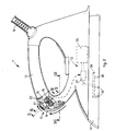
fig. 2 is a lateral view, partly in section along the line from II to II of the command device infig. 1 in a first operating position; -
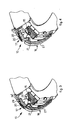
fig. 3 is an enlarged detail of the command device infig. 1 , in a second operating position; -
fig. 4 is an enlarged detail of the command device infig. 1 , in a third operating position; -
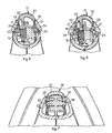
fig. 5 is a section from V to V offig. 2 ; -
fig. 6 is a section from VI to VI offig. 2 ; -
fig. 7 is a section from VII to VII offig. 2 . - With reference to
fig. 1 , acommand device 10 according to the present invention is applied for the delivery of steam and is arranged in the front part of aniron 11. - The iron 11 (
fig. 2 ) comprises ahandle 13 arranged on a median plane which passes through theiron 11 longitudinally, ametal ironing plate 14, heated by means of electric resistances, anelectric cable 19 to feed the various devices inside theiron 11, and a circuit to deliver thesteam 12. - The circuit to deliver the
steam 12, of known type, comprises as schematized infig. 2 , aboiler 35 where the water is heated, for example by means of an electric resistance, and a plurality of throughholes 36, only partly shown here, arranged on theironing plate 14, from which the steam selectively emerges. - The circuit to deliver the
steam 12 also comprises an electrically commanded valve, or electrovalve 37, which is connected upstream with theboiler 35 and downstream, by means of a plurality ofpipes 38, only partly shown, with the throughholes 36. Theelectrovalve 37 can be selectively opened to obtain the delivery of the steam. - The
command device 10 comprises anelectric switch 15 of a known type, arranged inside thehandle 13, having a mushroom-shaped actuator 16 and connected to theelectrovalve 37 of the circuit to deliver thesteam 12. - By actuating the
command device 10, the user causes theelectrovalve 37 to be activated and hence the delivery of the steam on the ironing plate through the throughholes 36. - The
command device 10 also comprises afirst button 17 and asecond button 18, made of synthetic material, or any material suitable for the purpose. - The
first button 17 is located on the front part of thehandle 13, is arranged on the median plane and is connected to theelectric switch 15 to activate the delivery of the steam. - The
second button 18 is associated with thefirst button 17 and comprises two fins 26 (fig. 1 ), lateral and opposite, shaped so as to at least partly surround thefirst button 17 and the front part of thehandle 13. - The
second button 18 also comprises alower zone 27, elongated in shape, which extends into the front zone of theiron 11. - The first button 17 (
figs. 3, 4 ,5 and 6 ) has a knurledouter zone 20 and twowalls 21 arranged inside thehandle 13, opposite each other and parallel to the median plane. Anintermediate wall 22 is arranged between the twowalls 21, parallel to them and able to contact theunderlying actuator 16 of theelectric switch 15. - Each
wall 21 comprises an attachment element 24 (figs. 5 and 6 ), cylindrical in shape, made in a single piece and able to be hinged in arespective seating 25 made inside eachfin 26 of thesecond button 18. - In this way, the
first button 17 can rotate with respect to theseatings 25, parallel to the median plane and according to the direction of the upper arrow shown infig. 2 . - The
lower zone 27 of the second button 18 (fig. 7 ) comprises twoarms 32 made in a single piece and inserted inside thehandle 13. Each of the twoarms 32 has acylindrical seating 34 parallel to the median plane. In the two cylindrical seatings 34 atubular element 33 is inserted which is attached to thehandle 13 and on which the twoarms 32 are free to rotate. - In this way, the
second button 18 can also rotate with respect to thetubular element 33 parallel to the median plane and according to the direction of the lower arrow shown infig. 2 . - With reference to
fig. 2 , thefirst button 17 and thesecond button 18 are in a first inactive position in which theintermediate wall 22 does not contact theactuator 16 of theelectric switch 15 and therefore no steam is delivered. - With reference to
fig. 3 , thefirst button 17 and/or thesecond button 18 are in a second actuation position in which theintermediate wall 22 contacts theactuator 16 of theelectric switch 15 driving the delivery of the steam. - The second actuation position is reached if the user directly actuates the
first button 17 or thesecond button 18 in any one direction of the directions indicated by the arrows infig. 1 , or any direction comprised among those illustrated. - If pressure is exerted on the
first button 17, it rotates parallel to the median plane carrying theintermediate wall 22 into contact with theactuator 16. - The
fins 26 of thesecond button 18 protrude with respect to thehandle 13, so that any direction of actuation on thefins 26 possesses a component parallel to the median plane and orthogonal to the external surface of thesecond button 18. - In this way, the
second button 18 can be actuated from any direction comprised between those shown infig. 1 . - With reference to
fig. 4 , thefirst button 17 is in a third position to keep delivery active, to reach which thefirst button 17 is rotated by the user so that astep 29 of thefirst button 17 is clamped in amating clamping seating 30 made in thehandle 13. - In the third position, the
intermediate wall 22 of thefirst button 17 remains thrust against theactuator 16 until the user rotates thefirst button 17 in the opposite direction, so as to detach and distance thestep 29 from the clampingseating 30. - Thanks to the extensive actuable surface that the first 17 and the
second button 18 have of thecommand device 10 according to the present invention, the user is considerably facilitated in all the ironing operations that provide the delivery of steam to the garment to be ironed. - It is clear that modifications and/or additions of parts may be made to the
command device 10 as described heretofore, without departing from the field and scope of the present invention. - It comes within the field of protection of the present invention to provide that the
second button 18 actuates theelectric switch 15 directly. - It is also provided that the
command device 10 does not have thefirst button 17 and comprises a button shaped so as to surround the front part of thehandle 13 and having a similar shape to that of thesecond button 18, which actuates theelectric switch 15 directly. - The
command device 10 can also be used in irons having the boiler to heat the water arranged outside the iron. - It is also provided that the
command device 10 can comprise more than two buttons, each of which is able to actuate theelectric switch 15 directly or indirectly. - It is also clear that, although the present invention has been described with reference to some specific examples, a person of skill in the art shall certainly be able to achieve many other equivalent forms of command device for the delivery of steam in an iron, having the characteristics as set forth in the claims and hence all coming within the field of protection defined thereby.
Claims (11)
- Command device for the delivery of steam in an iron (11) having a handle (13) normally arranged on a median plane that passes longitudinally through said iron (11), and a delivery circuit of the steam (12), wherein said command device comprises an electric switch (15) arranged in said handle (13), associated with said delivery circuit of the steam (12), and actuation means (17, 18) arranged in correspondence with the front part of said handle (13) and connected to said electric switch (15) in order to activate the delivery of the steam, characterized in that said actuation means (17, 18) is shaped so as to at least partly surround said front part of said handle (13) and is able to be actuated both frontally and laterally, and also from above with respect to said handle (13) in order to cause the actuation of said electric switch (15).
- Command device as in claim 1, characterized in that constraint means (21, 24, 25, 32, 33, 34) is provided to constrain said actuation means (17, 18) to said iron (11).
- Command device as in claim 1 or 2, characterized in that clamping means (29, 30) is provided to keep at least part of said actuation means (17, 18) selectively and temporarily thrust against said electric switch (15).
- Command device as in claim 3, characterized in that said actuation means (17, 18) includes (i) a first inactive position, in which said electric switch (15) is not actuated, (ii) a second actuation position, determined by said constraint means (21, 24, 25, 32, 33, 34), in which at least part of said actuation means (17, 18) contacts said electric switch (15) in order to activate the delivery of steam, and (iii) a third position to keep the delivery of steam active, in which by means of said clamping means (29, 30), at least a part of said actuation means (17, 18) is kept in contact against said electric switch (15).
- Command device as in any claim hereinbefore, characterized in that said actuation means comprises a first actuation element (17) connected mechanically to said electric switch (15), and a second actuation element (18) associated with said first actuation element (17) and able to cooperate with said first actuation element (17) in order to actuate the electric switch (15).
- Command device as in claims 2 and 5, characterized in that the constraint means associated with said first actuation element (17) comprises at least two walls (21), each of which has an attachment element (24) able to be hinged in a respective seating (25) made inside said second actuation element (18).
- Command device as in claims 2 and 5, characterized in that the constraint means associated with said second actuation element (18) comprises at least two arms (32) and at least a tubular element (33) attached to said handle (13), each of said arms (32) having a respective seating (34) in which said tubular element (33) is inserted.
- Command device as in claim 5, 6 or 7, characterized in that said second actuation element (18) comprises two lateral and opposite fins (26) shaped so as to at least partly surround said first actuation element (17) and the front part of said handle (13).
- Command device as in claim 8, characterized in that said fins (26) protrude with respect to said handle (13).
- Command device as in claims 3 and 5, characterized in that said clamping means (29, 30) is associated with said first actuation element (17).
- Command device as in any claim hereinbefore, characterized in that it is electrically connected to valve means (37) which connects one or more pipes to deliver steam (38) to through holes (36) present on an ironing plate (14) of said iron (11).
Applications Claiming Priority (1)
| Application Number | Priority Date | Filing Date | Title |
|---|---|---|---|
| IT000197A ITUD20040197A1 (en) | 2004-10-22 | 2004-10-22 | COMMAND DEVICE FOR DELIVERY OF |
Publications (2)
| Publication Number | Publication Date |
|---|---|
| EP1650345A1 EP1650345A1 (en) | 2006-04-26 |
| EP1650345B1 true EP1650345B1 (en) | 2008-07-16 |
Family
ID=34956787
Family Applications (1)
| Application Number | Title | Priority Date | Filing Date |
|---|---|---|---|
| EP05109798A Expired - Lifetime EP1650345B1 (en) | 2004-10-22 | 2005-10-20 | Command device for the delivery of steam in an iron |
Country Status (5)
| Country | Link |
|---|---|
| EP (1) | EP1650345B1 (en) |
| AT (1) | ATE401448T1 (en) |
| DE (1) | DE602005008159D1 (en) |
| ES (1) | ES2313225T3 (en) |
| IT (1) | ITUD20040197A1 (en) |
Cited By (1)
| Publication number | Priority date | Publication date | Assignee | Title |
|---|---|---|---|---|
| DE102014100753A1 (en) * | 2014-01-23 | 2015-07-23 | Miele & Cie. Kg | Ironing device with a steam generator |
Families Citing this family (1)
| Publication number | Priority date | Publication date | Assignee | Title |
|---|---|---|---|---|
| ITMI20120742A1 (en) * | 2012-05-03 | 2013-11-04 | Pony S P A | STEAM IRONING DEVICE |
Family Cites Families (3)
| Publication number | Priority date | Publication date | Assignee | Title |
|---|---|---|---|---|
| JP2589716B2 (en) * | 1987-12-03 | 1997-03-12 | 松下電器産業株式会社 | Steam iron |
| WO2000024960A1 (en) * | 1998-10-27 | 2000-05-04 | Divelit S.A. | Steam controlling device for steam iron |
| EP1043441A1 (en) * | 1999-04-07 | 2000-10-11 | San Marco Piccoli Elettrodomestici s.r.l. | Instantaneous steam iron with container and pump incorporated |
-
2004
- 2004-10-22 IT IT000197A patent/ITUD20040197A1/en unknown
-
2005
- 2005-10-20 ES ES05109798T patent/ES2313225T3/en not_active Expired - Lifetime
- 2005-10-20 DE DE602005008159T patent/DE602005008159D1/en not_active Expired - Lifetime
- 2005-10-20 EP EP05109798A patent/EP1650345B1/en not_active Expired - Lifetime
- 2005-10-20 AT AT05109798T patent/ATE401448T1/en not_active IP Right Cessation
Cited By (1)
| Publication number | Priority date | Publication date | Assignee | Title |
|---|---|---|---|---|
| DE102014100753A1 (en) * | 2014-01-23 | 2015-07-23 | Miele & Cie. Kg | Ironing device with a steam generator |
Also Published As
| Publication number | Publication date |
|---|---|
| ES2313225T3 (en) | 2009-03-01 |
| EP1650345A1 (en) | 2006-04-26 |
| DE602005008159D1 (en) | 2008-08-28 |
| ATE401448T1 (en) | 2008-08-15 |
| ITUD20040197A1 (en) | 2005-01-22 |
Similar Documents
| Publication | Publication Date | Title |
|---|---|---|
| EP3596264B1 (en) | Domestic appliance for ironing clothes and similars | |
| FR2891284B3 (en) | CLOTHING MAINTENANCE SYSTEM | |
| EP1650345A1 (en) | Command device for the delivery of steam in an iron | |
| US1958876A (en) | Steaming iron | |
| KR900008497B1 (en) | Electric kettle consisting of a vessel supported on a base-plate wich is connected electrically to the power supply system | |
| WO2005009171A1 (en) | Hand hair dryer with two handle grips | |
| EP3325706B1 (en) | Ironing board with steam-releasing board for domestic use with various ironing modes | |
| US20220053992A1 (en) | Device for the hot cleaning of various types of surfaces | |
| CN109082868B (en) | Ironing appliance equipped with a tank heated by means of a first and a second electric resistance | |
| RU2664238C1 (en) | Ironing station with multiple stream flows | |
| FR2868676B1 (en) | ELECTRICAL LIQUID HEATING APPARATUS | |
| DE10211879A1 (en) | Iron for steam ironing device incorporates sliding operating switch for suction/blower unit of ironing device | |
| US3080469A (en) | Wire stripping tool | |
| US1249464A (en) | Laundry appliance. | |
| KR100205188B1 (en) | Control of thermal power at ignition of gas combustor | |
| US3824719A (en) | Seambuster iron | |
| US1842784A (en) | Ironing apparatus | |
| EP3135808B1 (en) | Household electrical appliance for treating laundry by steam, comprising a button for controlling steam diffusion | |
| US2569807A (en) | Electric marking machine | |
| EP1650360B1 (en) | Faucet with additional discharge port | |
| EP3947805B1 (en) | Ironing apparatus and method of ironing | |
| EP2049728B1 (en) | Device to regulate the temperature of an ironing apparatus | |
| US1753559A (en) | Sadiron | |
| US1536271A (en) | Ironing board | |
| US1521748A (en) | Handle for electric irons |
Legal Events
| Date | Code | Title | Description |
|---|---|---|---|
| PUAI | Public reference made under article 153(3) epc to a published international application that has entered the european phase |
Free format text: ORIGINAL CODE: 0009012 |
|
| AK | Designated contracting states |
Kind code of ref document: A1 Designated state(s): AT BE BG CH CY CZ DE DK EE ES FI FR GB GR HU IE IS IT LI LT LU LV MC NL PL PT RO SE SI SK TR |
|
| AX | Request for extension of the european patent |
Extension state: AL BA HR MK YU |
|
| 17P | Request for examination filed |
Effective date: 20061025 |
|
| AKX | Designation fees paid |
Designated state(s): AT BE BG CH CY CZ DE DK EE ES FI FR GB GR HU IE IS IT LI LT LU LV MC NL PL PT RO SE SI SK TR |
|
| GRAP | Despatch of communication of intention to grant a patent |
Free format text: ORIGINAL CODE: EPIDOSNIGR1 |
|
| GRAS | Grant fee paid |
Free format text: ORIGINAL CODE: EPIDOSNIGR3 |
|
| GRAA | (expected) grant |
Free format text: ORIGINAL CODE: 0009210 |
|
| AK | Designated contracting states |
Kind code of ref document: B1 Designated state(s): AT BE BG CH CY CZ DE DK EE ES FI FR GB GR HU IE IS IT LI LT LU LV MC NL PL PT RO SE SI SK TR |
|
| REG | Reference to a national code |
Ref country code: GB Ref legal event code: FG4D |
|
| RIN1 | Information on inventor provided before grant (corrected) |
Inventor name: RIGO, FLAVIO Inventor name: ANTONEL, ALESSANDRO |
|
| REG | Reference to a national code |
Ref country code: CH Ref legal event code: EP |
|
| REF | Corresponds to: |
Ref document number: 602005008159 Country of ref document: DE Date of ref document: 20080828 Kind code of ref document: P |
|
| REG | Reference to a national code |
Ref country code: IE Ref legal event code: FG4D |
|
| REG | Reference to a national code |
Ref country code: GR Ref legal event code: EP Ref document number: 20080402800 Country of ref document: GR |
|
| NLV1 | Nl: lapsed or annulled due to failure to fulfill the requirements of art. 29p and 29m of the patents act | ||
| PG25 | Lapsed in a contracting state [announced via postgrant information from national office to epo] |
Ref country code: NL Free format text: LAPSE BECAUSE OF FAILURE TO SUBMIT A TRANSLATION OF THE DESCRIPTION OR TO PAY THE FEE WITHIN THE PRESCRIBED TIME-LIMIT Effective date: 20080716 Ref country code: LT Free format text: LAPSE BECAUSE OF FAILURE TO SUBMIT A TRANSLATION OF THE DESCRIPTION OR TO PAY THE FEE WITHIN THE PRESCRIBED TIME-LIMIT Effective date: 20080716 Ref country code: IS Free format text: LAPSE BECAUSE OF FAILURE TO SUBMIT A TRANSLATION OF THE DESCRIPTION OR TO PAY THE FEE WITHIN THE PRESCRIBED TIME-LIMIT Effective date: 20081116 |
|
| PG25 | Lapsed in a contracting state [announced via postgrant information from national office to epo] |
Ref country code: LV Free format text: LAPSE BECAUSE OF FAILURE TO SUBMIT A TRANSLATION OF THE DESCRIPTION OR TO PAY THE FEE WITHIN THE PRESCRIBED TIME-LIMIT Effective date: 20080716 Ref country code: FI Free format text: LAPSE BECAUSE OF FAILURE TO SUBMIT A TRANSLATION OF THE DESCRIPTION OR TO PAY THE FEE WITHIN THE PRESCRIBED TIME-LIMIT Effective date: 20080716 Ref country code: BG Free format text: LAPSE BECAUSE OF FAILURE TO SUBMIT A TRANSLATION OF THE DESCRIPTION OR TO PAY THE FEE WITHIN THE PRESCRIBED TIME-LIMIT Effective date: 20081016 Ref country code: PT Free format text: LAPSE BECAUSE OF FAILURE TO SUBMIT A TRANSLATION OF THE DESCRIPTION OR TO PAY THE FEE WITHIN THE PRESCRIBED TIME-LIMIT Effective date: 20081216 Ref country code: SI Free format text: LAPSE BECAUSE OF FAILURE TO SUBMIT A TRANSLATION OF THE DESCRIPTION OR TO PAY THE FEE WITHIN THE PRESCRIBED TIME-LIMIT Effective date: 20080716 Ref country code: AT Free format text: LAPSE BECAUSE OF FAILURE TO SUBMIT A TRANSLATION OF THE DESCRIPTION OR TO PAY THE FEE WITHIN THE PRESCRIBED TIME-LIMIT Effective date: 20080716 |
|
| REG | Reference to a national code |
Ref country code: ES Ref legal event code: FG2A Ref document number: 2313225 Country of ref document: ES Kind code of ref document: T3 |
|
| PG25 | Lapsed in a contracting state [announced via postgrant information from national office to epo] |
Ref country code: BE Free format text: LAPSE BECAUSE OF FAILURE TO SUBMIT A TRANSLATION OF THE DESCRIPTION OR TO PAY THE FEE WITHIN THE PRESCRIBED TIME-LIMIT Effective date: 20080716 |
|
| PG25 | Lapsed in a contracting state [announced via postgrant information from national office to epo] |
Ref country code: EE Free format text: LAPSE BECAUSE OF FAILURE TO SUBMIT A TRANSLATION OF THE DESCRIPTION OR TO PAY THE FEE WITHIN THE PRESCRIBED TIME-LIMIT Effective date: 20080716 Ref country code: DK Free format text: LAPSE BECAUSE OF FAILURE TO SUBMIT A TRANSLATION OF THE DESCRIPTION OR TO PAY THE FEE WITHIN THE PRESCRIBED TIME-LIMIT Effective date: 20080716 |
|
| PLBE | No opposition filed within time limit |
Free format text: ORIGINAL CODE: 0009261 |
|
| STAA | Information on the status of an ep patent application or granted ep patent |
Free format text: STATUS: NO OPPOSITION FILED WITHIN TIME LIMIT |
|
| PG25 | Lapsed in a contracting state [announced via postgrant information from national office to epo] |
Ref country code: MC Free format text: LAPSE BECAUSE OF NON-PAYMENT OF DUE FEES Effective date: 20081031 Ref country code: CZ Free format text: LAPSE BECAUSE OF FAILURE TO SUBMIT A TRANSLATION OF THE DESCRIPTION OR TO PAY THE FEE WITHIN THE PRESCRIBED TIME-LIMIT Effective date: 20080716 Ref country code: RO Free format text: LAPSE BECAUSE OF FAILURE TO SUBMIT A TRANSLATION OF THE DESCRIPTION OR TO PAY THE FEE WITHIN THE PRESCRIBED TIME-LIMIT Effective date: 20080716 Ref country code: SK Free format text: LAPSE BECAUSE OF FAILURE TO SUBMIT A TRANSLATION OF THE DESCRIPTION OR TO PAY THE FEE WITHIN THE PRESCRIBED TIME-LIMIT Effective date: 20080716 |
|
| 26N | No opposition filed |
Effective date: 20090417 |
|
| REG | Reference to a national code |
Ref country code: IE Ref legal event code: MM4A |
|
| PG25 | Lapsed in a contracting state [announced via postgrant information from national office to epo] |
Ref country code: IE Free format text: LAPSE BECAUSE OF NON-PAYMENT OF DUE FEES Effective date: 20081020 |
|
| PG25 | Lapsed in a contracting state [announced via postgrant information from national office to epo] |
Ref country code: SE Free format text: LAPSE BECAUSE OF FAILURE TO SUBMIT A TRANSLATION OF THE DESCRIPTION OR TO PAY THE FEE WITHIN THE PRESCRIBED TIME-LIMIT Effective date: 20081016 |
|
| PGFP | Annual fee paid to national office [announced via postgrant information from national office to epo] |
Ref country code: DE Payment date: 20091026 Year of fee payment: 5 |
|
| PGFP | Annual fee paid to national office [announced via postgrant information from national office to epo] |
Ref country code: FR Payment date: 20091110 Year of fee payment: 5 |
|
| PG25 | Lapsed in a contracting state [announced via postgrant information from national office to epo] |
Ref country code: PL Free format text: LAPSE BECAUSE OF FAILURE TO SUBMIT A TRANSLATION OF THE DESCRIPTION OR TO PAY THE FEE WITHIN THE PRESCRIBED TIME-LIMIT Effective date: 20080716 |
|
| REG | Reference to a national code |
Ref country code: CH Ref legal event code: PL |
|
| PGFP | Annual fee paid to national office [announced via postgrant information from national office to epo] |
Ref country code: GR Payment date: 20091015 Year of fee payment: 5 |
|
| PG25 | Lapsed in a contracting state [announced via postgrant information from national office to epo] |
Ref country code: LU Free format text: LAPSE BECAUSE OF NON-PAYMENT OF DUE FEES Effective date: 20081020 Ref country code: CY Free format text: LAPSE BECAUSE OF FAILURE TO SUBMIT A TRANSLATION OF THE DESCRIPTION OR TO PAY THE FEE WITHIN THE PRESCRIBED TIME-LIMIT Effective date: 20080716 Ref country code: HU Free format text: LAPSE BECAUSE OF FAILURE TO SUBMIT A TRANSLATION OF THE DESCRIPTION OR TO PAY THE FEE WITHIN THE PRESCRIBED TIME-LIMIT Effective date: 20090117 |
|
| PG25 | Lapsed in a contracting state [announced via postgrant information from national office to epo] |
Ref country code: TR Free format text: LAPSE BECAUSE OF FAILURE TO SUBMIT A TRANSLATION OF THE DESCRIPTION OR TO PAY THE FEE WITHIN THE PRESCRIBED TIME-LIMIT Effective date: 20080716 |
|
| PG25 | Lapsed in a contracting state [announced via postgrant information from national office to epo] |
Ref country code: LI Free format text: LAPSE BECAUSE OF NON-PAYMENT OF DUE FEES Effective date: 20091031 Ref country code: CH Free format text: LAPSE BECAUSE OF NON-PAYMENT OF DUE FEES Effective date: 20091031 |
|
| PG25 | Lapsed in a contracting state [announced via postgrant information from national office to epo] |
Ref country code: GB Free format text: LAPSE BECAUSE OF NON-PAYMENT OF DUE FEES Effective date: 20091020 |
|
| PG25 | Lapsed in a contracting state [announced via postgrant information from national office to epo] |
Ref country code: GR Free format text: LAPSE BECAUSE OF NON-PAYMENT OF DUE FEES Effective date: 20110503 Ref country code: FR Free format text: LAPSE BECAUSE OF NON-PAYMENT OF DUE FEES Effective date: 20101102 |
|
| REG | Reference to a national code |
Ref country code: FR Ref legal event code: ST Effective date: 20110630 |
|
| REG | Reference to a national code |
Ref country code: DE Ref legal event code: R119 Ref document number: 602005008159 Country of ref document: DE Effective date: 20110502 |
|
| PGFP | Annual fee paid to national office [announced via postgrant information from national office to epo] |
Ref country code: ES Payment date: 20121026 Year of fee payment: 8 |
|
| PG25 | Lapsed in a contracting state [announced via postgrant information from national office to epo] |
Ref country code: DE Free format text: LAPSE BECAUSE OF NON-PAYMENT OF DUE FEES Effective date: 20110502 |
|
| REG | Reference to a national code |
Ref country code: ES Ref legal event code: FD2A Effective date: 20141107 |
|
| PG25 | Lapsed in a contracting state [announced via postgrant information from national office to epo] |
Ref country code: ES Free format text: LAPSE BECAUSE OF NON-PAYMENT OF DUE FEES Effective date: 20131021 |
|
| PGFP | Annual fee paid to national office [announced via postgrant information from national office to epo] |
Ref country code: IT Payment date: 20201022 Year of fee payment: 16 |
|
| PG25 | Lapsed in a contracting state [announced via postgrant information from national office to epo] |
Ref country code: IT Free format text: LAPSE BECAUSE OF NON-PAYMENT OF DUE FEES Effective date: 20211020 |