EP1650175A1 - Double-layer glass spacer forming method - Google Patents
Double-layer glass spacer forming method Download PDFInfo
- Publication number
- EP1650175A1 EP1650175A1 EP04746442A EP04746442A EP1650175A1 EP 1650175 A1 EP1650175 A1 EP 1650175A1 EP 04746442 A EP04746442 A EP 04746442A EP 04746442 A EP04746442 A EP 04746442A EP 1650175 A1 EP1650175 A1 EP 1650175A1
- Authority
- EP
- European Patent Office
- Prior art keywords
- spacer
- applicator head
- forming material
- head
- discharge port
- Prior art date
- Legal status (The legal status is an assumption and is not a legal conclusion. Google has not performed a legal analysis and makes no representation as to the accuracy of the status listed.)
- Withdrawn
Links
Images


Classifications
-
- C—CHEMISTRY; METALLURGY
- C03—GLASS; MINERAL OR SLAG WOOL
- C03C—CHEMICAL COMPOSITION OF GLASSES, GLAZES OR VITREOUS ENAMELS; SURFACE TREATMENT OF GLASS; SURFACE TREATMENT OF FIBRES OR FILAMENTS MADE FROM GLASS, MINERALS OR SLAGS; JOINING GLASS TO GLASS OR OTHER MATERIALS
- C03C27/00—Joining pieces of glass to pieces of other inorganic material; Joining glass to glass other than by fusing
- C03C27/06—Joining glass to glass by processes other than fusing
-
- E—FIXED CONSTRUCTIONS
- E06—DOORS, WINDOWS, SHUTTERS, OR ROLLER BLINDS IN GENERAL; LADDERS
- E06B—FIXED OR MOVABLE CLOSURES FOR OPENINGS IN BUILDINGS, VEHICLES, FENCES OR LIKE ENCLOSURES IN GENERAL, e.g. DOORS, WINDOWS, BLINDS, GATES
- E06B3/00—Window sashes, door leaves, or like elements for closing wall or like openings; Layout of fixed or moving closures, e.g. windows in wall or like openings; Features of rigidly-mounted outer frames relating to the mounting of wing frames
- E06B3/66—Units comprising two or more parallel glass or like panes permanently secured together
- E06B3/673—Assembling the units
- E06B3/67326—Assembling spacer elements with the panes
- E06B3/6733—Assembling spacer elements with the panes by applying, e.g. extruding, a ribbon of hardenable material on or between the panes
-
- B—PERFORMING OPERATIONS; TRANSPORTING
- B29—WORKING OF PLASTICS; WORKING OF SUBSTANCES IN A PLASTIC STATE IN GENERAL
- B29C—SHAPING OR JOINING OF PLASTICS; SHAPING OF MATERIAL IN A PLASTIC STATE, NOT OTHERWISE PROVIDED FOR; AFTER-TREATMENT OF THE SHAPED PRODUCTS, e.g. REPAIRING
- B29C48/00—Extrusion moulding, i.e. expressing the moulding material through a die or nozzle which imparts the desired form; Apparatus therefor
- B29C48/03—Extrusion moulding, i.e. expressing the moulding material through a die or nozzle which imparts the desired form; Apparatus therefor characterised by the shape of the extruded material at extrusion
- B29C48/06—Rod-shaped
-
- B—PERFORMING OPERATIONS; TRANSPORTING
- B29—WORKING OF PLASTICS; WORKING OF SUBSTANCES IN A PLASTIC STATE IN GENERAL
- B29C—SHAPING OR JOINING OF PLASTICS; SHAPING OF MATERIAL IN A PLASTIC STATE, NOT OTHERWISE PROVIDED FOR; AFTER-TREATMENT OF THE SHAPED PRODUCTS, e.g. REPAIRING
- B29C48/00—Extrusion moulding, i.e. expressing the moulding material through a die or nozzle which imparts the desired form; Apparatus therefor
- B29C48/15—Extrusion moulding, i.e. expressing the moulding material through a die or nozzle which imparts the desired form; Apparatus therefor incorporating preformed parts or layers, e.g. extrusion moulding around inserts
-
- B—PERFORMING OPERATIONS; TRANSPORTING
- B29—WORKING OF PLASTICS; WORKING OF SUBSTANCES IN A PLASTIC STATE IN GENERAL
- B29C—SHAPING OR JOINING OF PLASTICS; SHAPING OF MATERIAL IN A PLASTIC STATE, NOT OTHERWISE PROVIDED FOR; AFTER-TREATMENT OF THE SHAPED PRODUCTS, e.g. REPAIRING
- B29C48/00—Extrusion moulding, i.e. expressing the moulding material through a die or nozzle which imparts the desired form; Apparatus therefor
- B29C48/15—Extrusion moulding, i.e. expressing the moulding material through a die or nozzle which imparts the desired form; Apparatus therefor incorporating preformed parts or layers, e.g. extrusion moulding around inserts
- B29C48/154—Coating solid articles, i.e. non-hollow articles
- B29C48/155—Partial coating thereof
-
- C—CHEMISTRY; METALLURGY
- C03—GLASS; MINERAL OR SLAG WOOL
- C03C—CHEMICAL COMPOSITION OF GLASSES, GLAZES OR VITREOUS ENAMELS; SURFACE TREATMENT OF GLASS; SURFACE TREATMENT OF FIBRES OR FILAMENTS MADE FROM GLASS, MINERALS OR SLAGS; JOINING GLASS TO GLASS OR OTHER MATERIALS
- C03C27/00—Joining pieces of glass to pieces of other inorganic material; Joining glass to glass other than by fusing
- C03C27/06—Joining glass to glass by processes other than fusing
- C03C27/10—Joining glass to glass by processes other than fusing with the aid of adhesive specially adapted for that purpose
-
- E—FIXED CONSTRUCTIONS
- E06—DOORS, WINDOWS, SHUTTERS, OR ROLLER BLINDS IN GENERAL; LADDERS
- E06B—FIXED OR MOVABLE CLOSURES FOR OPENINGS IN BUILDINGS, VEHICLES, FENCES OR LIKE ENCLOSURES IN GENERAL, e.g. DOORS, WINDOWS, BLINDS, GATES
- E06B3/00—Window sashes, door leaves, or like elements for closing wall or like openings; Layout of fixed or moving closures, e.g. windows in wall or like openings; Features of rigidly-mounted outer frames relating to the mounting of wing frames
- E06B3/66—Units comprising two or more parallel glass or like panes permanently secured together
-
- E—FIXED CONSTRUCTIONS
- E06—DOORS, WINDOWS, SHUTTERS, OR ROLLER BLINDS IN GENERAL; LADDERS
- E06B—FIXED OR MOVABLE CLOSURES FOR OPENINGS IN BUILDINGS, VEHICLES, FENCES OR LIKE ENCLOSURES IN GENERAL, e.g. DOORS, WINDOWS, BLINDS, GATES
- E06B3/00—Window sashes, door leaves, or like elements for closing wall or like openings; Layout of fixed or moving closures, e.g. windows in wall or like openings; Features of rigidly-mounted outer frames relating to the mounting of wing frames
- E06B3/66—Units comprising two or more parallel glass or like panes permanently secured together
- E06B3/673—Assembling the units
- E06B3/67365—Transporting or handling panes, spacer frames or units during assembly
- E06B2003/67378—Apparatus travelling around the periphery of the pane or the unit
Definitions
- the present invention relates to a method of forming a spacer of double glazing, and more particularly, relates to a method of forming a spacer of double glazing capable of improving productivity.
- double glazing In a construction field, an automobile field and the like, double glazing has been heretofore used for the purpose of heat insulation, dew condensation prevention, sound insulation and the like.
- double glazing there is known double glazing having glass plates, a spacer placed between the peripheries of the glass plates and an airtightly sealed air space formed between the glass plates, the spacer being formed of rubber, resin or the like having a drying agent mixed therein, the airtightly sealed air space being shut out from ambient air (see Japanese patent application Kokai publication Nos. 10 (1998)-110072 and 2001-354949, for example).
- a multi-joint robot having an applicator head for applying a spacer forming material is used, and while the applicator head is being moved by the multi-joint robot along the periphery of the upper surface of one glass plate which is horizontally held, the spacer forming material is applied at a constant application amount to automatically form the spacer.
- the multi-joint robot rotates the applicator head to change the direction of the discharge port of the applicator head that discharges the spacer forming material.
- the applicator head is moved along the periphery at a constant speed in accordance with the rotation speed of the applicator head in order to obtain a good spacer shape.
- the movement speed of the applicator head that is, the speed of forming a spacer has to depend on the rotation speed of the applicator head, which hinders improvement in productivity.
- the present invention provides a method of forming a spacer of double glazing by using a multi-joint robot to which an applicator head for applying a spacer forming material is rotatably attached and by applying the spacer forming material from the applicator head while the applicator head is being moved by the multi-joint robot along a periphery of an upper surface of one glass plate, the application head having a discharge port for the spacer forming material, which is directed to one direction, the periphery of the glass plate having linear regions and corner regions which follow the linear regions, the method comprising the steps of: discharging the spacer forming material from the discharge port of the applicator head in each linear region; stopping the discharge of the spacer forming material from the discharge port of the applicator head in each corner region; and rotating the application head in each corner region to change the direction of the discharge port of the applicator head to a direction suitable for application in the next linear region which follows the corner region.
- the spacer forming material since discharging of the spacer forming material from the discharge port of the applicator head is stopped in the corner regions, a large amount of the spacer forming material do not run off a predetermined application area in the glass plate outward. Therefore, even if the applicator head that applies the spacer forming material is moved at a high speed in the linear regions without depending on the rotation speed of the applicator head while the applicator head is moved at a speed corresponding to the rotation speed of the applicator head or lower in the corner regions, the spacer with a good appearance can be formed. Accordingly, the spacer having a good appearance can be formed without depending on the rotation speed of the applicator head in the linear regions, and productivity can be improved.
- Fig. 1 shows one example of double glazing having a spacer formed by use of a method of forming a spacer of double glazing according to the present invention.
- Double glazing G1 shown in Fig. 1 has rectangular glass plates 1 and 2, and a spacer 5 with primary sealing agent layers 3 and 4 on its upper and lower surfaces, disposed between the peripheries 1a and 2a of the glass plates 1 and 2.
- An airtightly sealed air space 6 surrounded by the spacer 5 is formed between the glass plates 1 and 2.
- a secondary sealing agent layer 7 is provided outwardly of the spacer 5 between the glass plates 1 and 2.
- the double glazing G1 described above is obtained by forming a spacer 5 on the periphery 1a of the upper surface 1X of one glass plate 1 which is horizontally placed, cooling the spacer 5, then press-attaching the other glass plate 2 thereon, and forming a secondary sealing agent layer 7.
- the method of forming a spacer of double glazing according to the present invention is used to form the spacer 5 of double glazing G1 as described above.
- Fig. 2 shows one example of a multi-joint robot used in the double glazing spacer forming method of the present invention.
- This multi-joint robot R includes a rotary table 10, a first swing arm assembly 11, a second swing arm assembly 12 and a third swing arm assembly 13.
- the rotary table 10 is fixed to the upper end of an axle 15 which protrudes on a base part 14. When the axle 15 rotates around its vertically extending rotation center axis 15a, the rotary table 10 rotates.
- the first swing arm assembly 11 which extends vertically, is connected at its lower end to the rotary table 10.
- the first swing arm assembly 11 can swing back and forth (right and left in Fig. 3) around its swing center axis 11a, horizontally extending to the right and left sides, located in its lower end.
- the second swing arm assembly 12 which extends back and forth, is connected at its rear end to the upper end of the first swing arm assembly 11.
- the second swing arm assembly 12 can swing up and down around its swing center axis 12a, horizontally extending to the right and left sides, located in its rear end.
- the second swing arm assembly 12 comprises a connection arm part 12X connected to the first swing arm assembly 11, and a rotating arm part 12Y which is rotatably attached to the connection arm part 12X.
- the rotating arm part 12Y rotates around its rotation center axis y extending back and forth.
- the third swing arm assembly 13 which extends vertically, is connected at its upper end to the front end of the second swing arm assembly 12.
- the third swing arm assembly 13 can swing back and forth around its swing center axis 13a, horizontally extending to the right and left sides, located in its upper end.
- An applicator head H for applying a spacer forming material is connected at its upper end to the lower end of the third swing arm assembly 13.
- the applicator head H can rotates around its vertically extending rotation center axis Ha.
- the applicator head H is moved along the periphery 1a of the set glass plate 1 by appropriately operating the rotary table 10, first swing arm assembly 11, second swing arm assembly 12 and third swing arm assembly 13 with actuators, not shown.
- the applicator head H includes a discharge port 20 for discharging a spacer forming material provided at its lower end.
- a passage 21 for supplying the spacer forming material mixed with a drying agent communicates with the discharge port 20, which is directed to one direction (horizontal direction).
- the passage 21 has upper and lower wall surfaces 22 and 23, and supply passages 24 and 25 for supplying a primary sealing agent to form the primary sealing agent layers 3 and 4 are open to the lower wall surfaces 22 and 23 near the discharge port 20.
- Discharged from the discharge port 20 is a layered body into which the spacer forming material and the sealing agent are layered, having the spacer 5 and the primary sealing agent layers 3 and 4 disposed on both of the upper and lower surfaces thereof.
- means 37 for supplying the spacer forming material mixed with the drying agent and means 38 for supplying the primary sealing agent are connected to the applicator head H through pipes 31, 32 and 33 and valves 34, 35 and 36.
- the double glazing spacer forming method of the present invention will be performed as described below by using the above-described multi-joint robot R and applicator head H.
- a rectangular glass plate 1 is set in a horizontal position.
- the applicator head H is placed in a start position in a first linear region a1 of the periphery 1a of the upper surface 1X of the glass plate 1.
- the discharge port 20 of the applicator head H is directed to a direction opposite to the movement direction of the applicator head H, which is indicated by the arrow K.
- This opposite direction is an application direction of the applicator head H in four linear regions a1, a2, a3 and a4 of the periphery 1a.
- the spacer forming material and the primary sealing agent are discharged from the discharge port 20 at a constant amount in a strip shape, thereby forming a layered body 8 having the spacer 5 and the primary sealing agent layers 3 and 4 disposed on both of the upper and lower surfaces thereof in the first linear region a1.
- the movement speed of the applicator head H in the linear region a1 is significantly faster (for example, 120 mm/sec.) than that in the corner regions of the periphery 1a.
- the valves 34, 35 and 36 are closed to stop discharge of the spacer forming material and the primary sealing agent from the discharge port 20.
- the multi-joint robot R rotates the applicator head H to change the direction of the discharge port 20 of the applicator head H, which has stopped discharge of the spacer forming material and the primary sealing agent, to a direction suitable for application in a second linear region a2 of the periphery 1a, which follows the first corner region b1.
- the movement speed of the applicator head H in the corner region b1 is a speed (for example, 60 mm/sec.) corresponding to the rotation speed of the applicator head H or lower.
- Fig. 6 shows one example of a preferred process of changing the direction. If the intersection of an application center line c1 in the first linear region a1 with an application center line c2 in the second linear region a2, located in the first corner region b1, is denoted by reference character A, the applicator head H which has reached the first corner region b1 and stopped discharge of the spacer forming material and the primary sealing agent is moved such that the discharge port 20 passes the intersection A and reaches a position B.
- the moved distance m can be set to, for example, about 5 mm.
- the applicator head H is rotated so as to direct the direction of the discharge port 20 slightly inward as indicated by an applicator head H'.
- the rotation angle of the applicator head is about 1 to 2°.
- the applicator head H When the discharge port 20 has moved to the position B, the applicator head H is directed to the second linear region a2 and moved toward the application center line c2 in the second linear region a2, rotating the applicator head H so as to direct the discharge port 20 outward as indicated by the arrow Q. The applicator head H is moved so as to return the discharge center n of the discharge port 20 to the application center line c2 when the applicator head H reaches the second linear region a2.
- valves 34, 34 and 36 are opened to discharge again from the discharge port 20 the layered body 8 in a strip shape comprising the spacer 5 and the primary sealing agent layers 3 and 4 disposed on both of the upper and lower surfaces thereof.
- the distance L1 from the position B to a position D at which the discharge of the spacer forming material and the primary sealing agent is stopped and the distance L2 from the position B to a position E at which the discharge of the spacer forming material and the primary sealing agent is started again may be set to about 10 mm, respectively, in consideration of a residual pressure in the pipes 31, 32 and 33.
- those distances are appropriately determined according to dimensions of the pipes, and the kinds of the spacer forming material and the like.
- the angle ⁇ between the direction of the discharge port 20 and the application center line c2 be set to about 5° at the position E where the discharge is started again, and that the angle ⁇ be gradually reduced from the position E and become 0° at a position F which is about 20 mm away from the position E to overlap the discharge center n of the discharge port 20 with the application center line c2.
- reference character S denotes a locus of movement of the discharge center n of the discharge port 20 in the area from the position D to the position F, indicated by a chain double-dashed line.
- the locus of movement of the discharge center n of the discharge port 20 in other areas is located on the application center lines.
- the applicator head H in Fig. 6 is simplified by showing it as a line with its both ends folded for ease of viewing the drawing. The direction of folding is the direction to which the discharge port 20 is directed.
- the applicator head H is moved from the second linear region a2 to the first linear region through a second corner region b2, a third linear region a3, a third corner region b3, a fourth linear region a4 and a fourth corner region b4.
- the discharge of the spacer forming material and the primary sealing agent from the discharge port 20 of the applicator head H is stopped and the applicator head H is rotated to change the direction of the discharge port 20 in the second to fourth corner regions b2, b3 and b4.
- the discharge of the spacer forming material and the primary sealing agent from the discharge port 20 of the applicator head H is stopped in the corner regions b1, b2, b3 and b4.
- large amounts of the spacer forming material and the primary sealing agent do not run off a predetermined application region of the glass plate 1 outward.
- the spacer 5 having the primary sealing agent layers 3 and 4 with a good appearance can be formed. Therefore, the spacer 5 having the primary sealing agent layers 3 and 4 with a good appearance can be formed without depending on the rotation speed of the applicator head H in the linear regions a1, a2, a3 and a4, and productivity can be improved.
- the spacer 5 having the primary sealing agent layers 3 and 4 with a good appearance can be formed by automatically controlling the application amount from the applicator head H and the movement speed of the applicator head H, which are easily interlocked with each other.
- the applicator head H When the applicator head H is moved in each of the corner regions b1, b2, b3 and b4, the applicator head H is moved to the position where the discharge port 20 passes the intersection A. Thereafter, while the applicator head H is being moved toward the linear region a2, a3, a4, a1 which follows the corner region b1, b2, b3, b4, the applicator head H returns to the application center line.
- the corners 9 of the spacer 5 including the primary sealing agent layers 3 and 4 (layered body 8) can be formed to have a sharp angle close to right angle. Consequently, appearance can be further improved, and a sufficient width for providing the secondary sealing agent layer 7 can be secured.
- the spacer forming material of which the spacer 5 is formed may includes a conventionally known spacer forming material made of rubber, thermoplastic resin, thermoplastic elastomer or the like mixed with a drying agent.
- a thermoplastic material such as thermoplastic resin or thermoplastic elastomer, for example, a thermoplastic elastomer composition disclosed in Japanese patent application Kokai publication No. 2000-119537 or a sealing agent composition including a spacer function and a sealing function, disclosed in Japanese patent application Kokai publication No. 2001-354949, is used for the spacer forming material.
- the sealing agent used for the primary sealing agent layers 3 and 4 is not particularly limited as long as the agent has a function of sealing the glass plates 1 and 2; for example, a hot-melt type adhesive formed of a butyl sealing agent composition or the like may be used.
- Examples of the glass plates 1 and 2 used for double glazing G1 may generally include glass plates for windows, doors and so on widely used in building materials, vehicles and the like, reinforced glass plates, glass plates in which metal lathe is embedded, glass plates having inner surfaces thinly coated with metal or other inorganic substances such as heat-ray absorbing glass plates, and acrylic resin plates and polycarbonate plates called organic glass plates.
- Double gazing for which the double glazing spacer forming method of the present invention is used is not limited to the double glazing G1 shown in Fig. 1, but may include, for example, double glazing G2 shown in Fig. 7.
- This double glazing G2 has no primary sealing agent layers 3 and 4, and includes only a spacer 5 and a secondary sealing agent layer 7 which are disposed between the glass plates 1 and 2.
- This spacer 5 is formed of a spacer forming material having a spacer function and a sealing function.
- an applicator head having no supply passages 24 and 25 for supplying the primary sealing agent may be used.
- the double glazing spacer forming method of the present invention can also be used for forming each spacer.
- the double glazing may be one having a structure with no secondary sealing agent layer 7.
- a spacer 4 having primary sealing agent layers 3 and 4 with a good appearance can be formed by automatically controlling the application amount from the applicator head H and the movement speed of the applicator head H interlocked with each other, the application amount from the applicator head H may be reduced when applied in the corner regions.
- the double glazing spacer forming method of the present invention having the beneficial effects described above can be very effectively utilized to form a spacer of double glazing for the purpose of heat insulation, dew condensation prevention, sound insulation and the like in a construction field, an automobile field and the like.
Landscapes
- Engineering & Computer Science (AREA)
- Chemical & Material Sciences (AREA)
- Mechanical Engineering (AREA)
- Life Sciences & Earth Sciences (AREA)
- Structural Engineering (AREA)
- Ceramic Engineering (AREA)
- Civil Engineering (AREA)
- Chemical Kinetics & Catalysis (AREA)
- General Chemical & Material Sciences (AREA)
- Geochemistry & Mineralogy (AREA)
- Materials Engineering (AREA)
- Organic Chemistry (AREA)
- Joining Of Glass To Other Materials (AREA)
- Application Of Or Painting With Fluid Materials (AREA)
Abstract
Description
- The present invention relates to a method of forming a spacer of double glazing, and more particularly, relates to a method of forming a spacer of double glazing capable of improving productivity.
- In a construction field, an automobile field and the like, double glazing has been heretofore used for the purpose of heat insulation, dew condensation prevention, sound insulation and the like. As such double glazing, there is known double glazing having glass plates, a spacer placed between the peripheries of the glass plates and an airtightly sealed air space formed between the glass plates, the spacer being formed of rubber, resin or the like having a drying agent mixed therein, the airtightly sealed air space being shut out from ambient air (see Japanese patent application Kokai publication Nos. 10 (1998)-110072 and 2001-354949, for example).
- When double glazing as described above is manufactured, the following two methods of forming a spacer have been well known (see Japanese patent application Kokai publication Nos. 8 (1996)-67537 and 10 (1998)-511072, for example). One is a method of forming a spacer by extruding a spacer forming material along and between the peripheries of two glass plates held with a predetermined space therebetween. The other is a method of forming a spacer by extruding a spacer forming material along the periphery of the upper surface of one glass plate before the other glass plate is press-attached thereon.
- In the latter method, a multi-joint robot having an applicator head for applying a spacer forming material is used, and while the applicator head is being moved by the multi-joint robot along the periphery of the upper surface of one glass plate which is horizontally held, the spacer forming material is applied at a constant application amount to automatically form the spacer. When the applicator head reaches each corner of the glass plate, the multi-joint robot rotates the applicator head to change the direction of the discharge port of the applicator head that discharges the spacer forming material.
- Recently, due to the intensifying competition among companies, reduction in costs of double glazing has been demanded. Therefore, in the foregoing method using the multi-joint robot, if productivity is improved by increasing the movement speed (60 mm/sec. or more) of the applicator head to reduce costs, a large amount of spacer forming material runs off a predetermined application area outward in each corner region of the glass plate, thereby deteriorating the appearance of the spacer that has been formed. This is because it is structurally impossible to make the rotation speed of the applicator head follow the increased movement speed of the applicator head.
- Consequently, in the process of automatically forming a spacer by use of a multi-joint robot, the applicator head is moved along the periphery at a constant speed in accordance with the rotation speed of the applicator head in order to obtain a good spacer shape. Thus, the movement speed of the applicator head, that is, the speed of forming a spacer has to depend on the rotation speed of the applicator head, which hinders improvement in productivity.
- It is an object of the present invention to provide a method of forming a spacer of double glazing capable of forming a spacer having a good appearance without depending on the rotation speed of an applicator head and of improving productivity.
- In order to achieve the above object, the present invention provides a method of forming a spacer of double glazing by using a multi-joint robot to which an applicator head for applying a spacer forming material is rotatably attached and by applying the spacer forming material from the applicator head while the applicator head is being moved by the multi-joint robot along a periphery of an upper surface of one glass plate, the application head having a discharge port for the spacer forming material, which is directed to one direction, the periphery of the glass plate having linear regions and corner regions which follow the linear regions, the method comprising the steps of: discharging the spacer forming material from the discharge port of the applicator head in each linear region; stopping the discharge of the spacer forming material from the discharge port of the applicator head in each corner region; and rotating the application head in each corner region to change the direction of the discharge port of the applicator head to a direction suitable for application in the next linear region which follows the corner region.
- According to the present invention described above, since discharging of the spacer forming material from the discharge port of the applicator head is stopped in the corner regions, a large amount of the spacer forming material do not run off a predetermined application area in the glass plate outward. Therefore, even if the applicator head that applies the spacer forming material is moved at a high speed in the linear regions without depending on the rotation speed of the applicator head while the applicator head is moved at a speed corresponding to the rotation speed of the applicator head or lower in the corner regions, the spacer with a good appearance can be formed. Accordingly, the spacer having a good appearance can be formed without depending on the rotation speed of the applicator head in the linear regions, and productivity can be improved.
-
- Fig. 1 is a cross-sectional view showing one example of double glazing having a spacer formed by use of a method of forming a spacer of double glazing according to the present invention.
- Fig. 2 is a side view showing one example of a multi-joint robot used in the method of forming a spacer of double glazing according to the present invention.
- Fig. 3 is a partially enlarged cross-sectional view of an applicator head used in the method of forming a spacer of double glazing according to the present invention.
- Fig. 4 is an explanatory view showing spacer forming material supply means and primary sealing agent supply means which are connected to the applicator head.
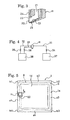
- Fig. 5 is a plan view showing the method of forming a spacer of double glazing according to the present invention.
- Fig. 6 is a partial plan view showing a preferable process of changing the direction of the discharge port of the applicator head.
- Fig. 7 is a cross-sectional view showing another example of double glazing having a spacer formed by use of the method of forming a spacer of double glazing according to the present invention.
- With reference to the accompanying drawings, an embodiment of the present invention will be described in detail below.
- Fig. 1 shows one example of double glazing having a spacer formed by use of a method of forming a spacer of double glazing according to the present invention. Double glazing G1 shown in Fig. 1 has
rectangular glass plates 1 and 2, and aspacer 5 with primarysealing agent layers 3 and 4 on its upper and lower surfaces, disposed between theperipheries glass plates 1 and 2. An airtightly sealedair space 6 surrounded by thespacer 5 is formed between theglass plates 1 and 2. A secondary sealing agent layer 7 is provided outwardly of thespacer 5 between theglass plates 1 and 2. - The double glazing G1 described above is obtained by forming a
spacer 5 on theperiphery 1a of theupper surface 1X of one glass plate 1 which is horizontally placed, cooling thespacer 5, then press-attaching theother glass plate 2 thereon, and forming a secondary sealing agent layer 7. The method of forming a spacer of double glazing according to the present invention is used to form thespacer 5 of double glazing G1 as described above. - With reference to Figs. 2 to 6, an embodiment of the double glazing spacer forming method of the present invention will be described below.
- Fig. 2 shows one example of a multi-joint robot used in the double glazing spacer forming method of the present invention. This multi-joint robot R includes a rotary table 10, a first
swing arm assembly 11, a secondswing arm assembly 12 and a thirdswing arm assembly 13. The rotary table 10 is fixed to the upper end of anaxle 15 which protrudes on abase part 14. When theaxle 15 rotates around its vertically extendingrotation center axis 15a, the rotary table 10 rotates. - The first
swing arm assembly 11, which extends vertically, is connected at its lower end to the rotary table 10. The firstswing arm assembly 11 can swing back and forth (right and left in Fig. 3) around itsswing center axis 11a, horizontally extending to the right and left sides, located in its lower end. - The second
swing arm assembly 12, which extends back and forth, is connected at its rear end to the upper end of the firstswing arm assembly 11. The secondswing arm assembly 12 can swing up and down around itsswing center axis 12a, horizontally extending to the right and left sides, located in its rear end. - The second
swing arm assembly 12 comprises aconnection arm part 12X connected to the firstswing arm assembly 11, and a rotatingarm part 12Y which is rotatably attached to theconnection arm part 12X. The rotatingarm part 12Y rotates around its rotation center axis y extending back and forth. - The third
swing arm assembly 13, which extends vertically, is connected at its upper end to the front end of the secondswing arm assembly 12. The thirdswing arm assembly 13 can swing back and forth around itsswing center axis 13a, horizontally extending to the right and left sides, located in its upper end. - An applicator head H for applying a spacer forming material is connected at its upper end to the lower end of the third
swing arm assembly 13. The applicator head H can rotates around its vertically extending rotation center axis Ha. - The applicator head H is moved along the
periphery 1a of the set glass plate 1 by appropriately operating the rotary table 10, firstswing arm assembly 11, secondswing arm assembly 12 and thirdswing arm assembly 13 with actuators, not shown. - As shown in Fig. 3, the applicator head H includes a
discharge port 20 for discharging a spacer forming material provided at its lower end. Apassage 21 for supplying the spacer forming material mixed with a drying agent communicates with thedischarge port 20, which is directed to one direction (horizontal direction). Thepassage 21 has upper andlower wall surfaces passages sealing agent layers 3 and 4 are open to thelower wall surfaces discharge port 20. Discharged from thedischarge port 20 is a layered body into which the spacer forming material and the sealing agent are layered, having thespacer 5 and the primarysealing agent layers 3 and 4 disposed on both of the upper and lower surfaces thereof. - As shown in Fig. 4, means 37 for supplying the spacer forming material mixed with the drying agent and means 38 for supplying the primary sealing agent are connected to the applicator head H through
pipes 31, 32 and 33 andvalves - The double glazing spacer forming method of the present invention will be performed as described below by using the above-described multi-joint robot R and applicator head H.
- First, as shown in Fig. 5, a rectangular glass plate 1 is set in a horizontal position. Next, the applicator head H is placed in a start position in a first linear region a1 of the
periphery 1a of theupper surface 1X of the glass plate 1. In this event, thedischarge port 20 of the applicator head H is directed to a direction opposite to the movement direction of the applicator head H, which is indicated by the arrow K. This opposite direction is an application direction of the applicator head H in four linear regions a1, a2, a3 and a4 of theperiphery 1a. - While the applicator head H is being moved in the direction indicated by the arrow K in the first linear region a1 along the
periphery 1a by the multi-joint robot R, the spacer forming material and the primary sealing agent are discharged from thedischarge port 20 at a constant amount in a strip shape, thereby forming alayered body 8 having thespacer 5 and the primarysealing agent layers 3 and 4 disposed on both of the upper and lower surfaces thereof in the first linear region a1. The movement speed of the applicator head H in the linear region a1 is significantly faster (for example, 120 mm/sec.) than that in the corner regions of theperiphery 1a. - When the applicator head H reaches a first corner region b1 of the
periphery 1a which follows the first linear region a1, thevalves discharge port 20. While the applicator head H is being moving in the first corner region b1, the multi-joint robot R rotates the applicator head H to change the direction of thedischarge port 20 of the applicator head H, which has stopped discharge of the spacer forming material and the primary sealing agent, to a direction suitable for application in a second linear region a2 of theperiphery 1a, which follows the first corner region b1. The movement speed of the applicator head H in the corner region b1 is a speed (for example, 60 mm/sec.) corresponding to the rotation speed of the applicator head H or lower. - Fig. 6 shows one example of a preferred process of changing the direction. If the intersection of an application center line c1 in the first linear region a1 with an application center line c2 in the second linear region a2, located in the first corner region b1, is denoted by reference character A, the applicator head H which has reached the first corner region b1 and stopped discharge of the spacer forming material and the primary sealing agent is moved such that the
discharge port 20 passes the intersection A and reaches a position B. Although depending on the spacer forming material and the primary sealing agent, the moved distance m can be set to, for example, about 5 mm. During the movement, it is preferable that the applicator head H is rotated so as to direct the direction of thedischarge port 20 slightly inward as indicated by an applicator head H'. The rotation angle of the applicator head is about 1 to 2°. - When the
discharge port 20 has moved to the position B, the applicator head H is directed to the second linear region a2 and moved toward the application center line c2 in the second linear region a2, rotating the applicator head H so as to direct thedischarge port 20 outward as indicated by the arrow Q. The applicator head H is moved so as to return the discharge center n of thedischarge port 20 to the application center line c2 when the applicator head H reaches the second linear region a2. - When the applicator head H reaches the second linear region a2, the
valves discharge port 20 thelayered body 8 in a strip shape comprising thespacer 5 and the primarysealing agent layers 3 and 4 disposed on both of the upper and lower surfaces thereof. - Normally, the distance L1 from the position B to a position D at which the discharge of the spacer forming material and the primary sealing agent is stopped and the distance L2 from the position B to a position E at which the discharge of the spacer forming material and the primary sealing agent is started again may be set to about 10 mm, respectively, in consideration of a residual pressure in the
pipes 31, 32 and 33. However, those distances are appropriately determined according to dimensions of the pipes, and the kinds of the spacer forming material and the like. It is preferable, in terms of smooth movement of the applicator head H by the multi-joint robot R and formation of thespacer 5 having a good appearance, that the angle α between the direction of thedischarge port 20 and the application center line c2 be set to about 5° at the position E where the discharge is started again, and that the angle α be gradually reduced from the position E and become 0° at a position F which is about 20 mm away from the position E to overlap the discharge center n of thedischarge port 20 with the application center line c2. - In Fig. 6, reference character S denotes a locus of movement of the discharge center n of the
discharge port 20 in the area from the position D to the position F, indicated by a chain double-dashed line. The locus of movement of the discharge center n of thedischarge port 20 in other areas is located on the application center lines. The applicator head H in Fig. 6 is simplified by showing it as a line with its both ends folded for ease of viewing the drawing. The direction of folding is the direction to which thedischarge port 20 is directed. - The applicator head H is moved from the second linear region a2 to the first linear region through a second corner region b2, a third linear region a3, a third corner region b3, a fourth linear region a4 and a fourth corner region b4. As in the case of the first corner region b1 described above, the discharge of the spacer forming material and the primary sealing agent from the
discharge port 20 of the applicator head H is stopped and the applicator head H is rotated to change the direction of thedischarge port 20 in the second to fourth corner regions b2, b3 and b4. - According to the present invention described above, the discharge of the spacer forming material and the primary sealing agent from the
discharge port 20 of the applicator head H is stopped in the corner regions b1, b2, b3 and b4. Thus, large amounts of the spacer forming material and the primary sealing agent do not run off a predetermined application region of the glass plate 1 outward. Consequently, even if the applicator head H is moved at a high speed in the linear regions a1, a2, a3 and a4 without depending on the rotation speed of the applicator head H, and, in the meantime, the applicator head H is moved at a speed corresponding to the rotation speed of the applicator head H or lower in the corner regions b1, b2, b3 and b4, thespacer 5 having the primarysealing agent layers 3 and 4 with a good appearance can be formed. Therefore, thespacer 5 having the primarysealing agent layers 3 and 4 with a good appearance can be formed without depending on the rotation speed of the applicator head H in the linear regions a1, a2, a3 and a4, and productivity can be improved. - Since the spacer forming material and the primary sealing agent are in a molten state and soft, even if the discharge of the spacer forming material and the primary sealing agent is stopped in the corner regions b1, b2, b3 and b4, there will occur no such defect as cutting of the
layered body 8 in a strip shape. - The
spacer 5 having the primarysealing agent layers 3 and 4 with a good appearance can be formed by automatically controlling the application amount from the applicator head H and the movement speed of the applicator head H, which are easily interlocked with each other. - When the applicator head H is moved in each of the corner regions b1, b2, b3 and b4, the applicator head H is moved to the position where the
discharge port 20 passes the intersection A. Thereafter, while the applicator head H is being moved toward the linear region a2, a3, a4, a1 which follows the corner region b1, b2, b3, b4, the applicator head H returns to the application center line. Thus, thecorners 9 of thespacer 5 including the primary sealing agent layers 3 and 4 (layered body 8) can be formed to have a sharp angle close to right angle. Consequently, appearance can be further improved, and a sufficient width for providing the secondary sealing agent layer 7 can be secured. - In the present invention, the spacer forming material of which the
spacer 5 is formed may includes a conventionally known spacer forming material made of rubber, thermoplastic resin, thermoplastic elastomer or the like mixed with a drying agent. Preferably, a thermoplastic material such as thermoplastic resin or thermoplastic elastomer, for example, a thermoplastic elastomer composition disclosed in Japanese patent application Kokai publication No. 2000-119537 or a sealing agent composition including a spacer function and a sealing function, disclosed in Japanese patent application Kokai publication No. 2001-354949, is used for the spacer forming material. - The sealing agent used for the primary
sealing agent layers 3 and 4 is not particularly limited as long as the agent has a function of sealing theglass plates 1 and 2; for example, a hot-melt type adhesive formed of a butyl sealing agent composition or the like may be used. - Examples of the
glass plates 1 and 2 used for double glazing G1 may generally include glass plates for windows, doors and so on widely used in building materials, vehicles and the like, reinforced glass plates, glass plates in which metal lathe is embedded, glass plates having inner surfaces thinly coated with metal or other inorganic substances such as heat-ray absorbing glass plates, and acrylic resin plates and polycarbonate plates called organic glass plates. - Double gazing for which the double glazing spacer forming method of the present invention is used is not limited to the double glazing G1 shown in Fig. 1, but may include, for example, double glazing G2 shown in Fig. 7. This double glazing G2 has no primary
sealing agent layers 3 and 4, and includes only aspacer 5 and a secondary sealing agent layer 7 which are disposed between theglass plates 1 and 2. Thisspacer 5 is formed of a spacer forming material having a spacer function and a sealing function. For formation of thespacer 5 of the double glazing G2 described above, an applicator head having nosupply passages - In the embodiment described above, a method of forming a
spacer 5 of double glazing having twoglass plates 1 and 2 has been described, but when double glazing having three or more glass plates and spacers disposed between the respective glass plates, the double glazing spacer forming method of the present invention can also be used for forming each spacer. The double glazing may be one having a structure with no secondary sealing agent layer 7. - If a
spacer 4 having primarysealing agent layers 3 and 4 with a good appearance can be formed by automatically controlling the application amount from the applicator head H and the movement speed of the applicator head H interlocked with each other, the application amount from the applicator head H may be reduced when applied in the corner regions. - The double glazing spacer forming method of the present invention having the beneficial effects described above can be very effectively utilized to form a spacer of double glazing for the purpose of heat insulation, dew condensation prevention, sound insulation and the like in a construction field, an automobile field and the like.
Claims (6)
- A method of forming a pacer of double glazing by using a multi-joint robot to which an applicator head for applying a spacer forming material is rotatably attached and by applying the spacer forming material from the applicator head while the applicator head is being moved by the multi-joint robot along a periphery of an upper surface of one glass plate, the application head having a discharge port for the spacer forming material, which is directed to one direction, the periphery of the glass plate having linear regions and corner regions which follow the linear regions, the method comprising the steps of:discharging the spacer forming material from the discharge port of the applicator head in each linear region;stopping the discharge of the spacer forming material from the discharge port of the applicator head in each corner region; androtating the application head in each corner region to change the direction of the discharge port of the applicator head to a direction suitable for application in the next linear region which follows the corner region.
- The method of forming a spacer of double glazing according to claim 1, wherein the step of rotating the application head in each corner region further comprises:moving the application head which has reached the corner region from the linear region until the discharge port passes an intersection A, the intersection A being an intersection of application center lines in the linear regions and being located in each corner region; andreturning the discharge head to the application center line in the linear region that follows the corner region while the application head is being moved toward the linear region that follows the corner region.
- The method of forming a spacer of double glazing according to any one of claims 1 and 2, wherein the step of discharging the spacer forming material in each linear region is performed such that a movement speed of the application head is faster in the linear regions than in the corner regions, and the step of rotating the application head in each corner region is performed such that the movement speed of the application head is equal to or lower than a speed corresponding to a rotation speed of the applicator head.
- The method of forming a spacer of double glazing according to any one of claims 1 to 3, wherein the glass plate is rectangular in shape.
- The method of forming a spacer of double glazing according to any one of claims 1 to 4, wherein the spacer forming material is made of a thermoplastic material mixed with a drying agent.
- The method of forming a spacer of double glazing according to any one of claims 1 to 5, wherein the applicator head applies the spacer forming material and a sealing agent, and the spacer forming material and the sealing agent are discharged in a layered state from the discharge port of the applicator head.
Applications Claiming Priority (2)
| Application Number | Priority Date | Filing Date | Title |
|---|---|---|---|
| JP2003180715 | 2003-06-25 | ||
| PCT/JP2004/008973 WO2005000763A1 (en) | 2003-06-25 | 2004-06-25 | Double-layer glass spacer forming method |
Publications (2)
| Publication Number | Publication Date |
|---|---|
| EP1650175A1 true EP1650175A1 (en) | 2006-04-26 |
| EP1650175A4 EP1650175A4 (en) | 2012-07-04 |
Family
ID=33549509
Family Applications (1)
| Application Number | Title | Priority Date | Filing Date |
|---|---|---|---|
| EP04746442A Withdrawn EP1650175A4 (en) | 2003-06-25 | 2004-06-25 | Double-layer glass spacer forming method |
Country Status (6)
| Country | Link |
|---|---|
| US (1) | US7485342B2 (en) |
| EP (1) | EP1650175A4 (en) |
| JP (1) | JP4682847B2 (en) |
| KR (1) | KR20060012028A (en) |
| CN (1) | CN100450948C (en) |
| WO (1) | WO2005000763A1 (en) |
Cited By (3)
| Publication number | Priority date | Publication date | Assignee | Title |
|---|---|---|---|---|
| WO2012015922A3 (en) * | 2010-07-28 | 2012-10-11 | First Solar, Inc. | Seal for photovoltaic module |
| US8336272B2 (en) | 2008-01-09 | 2012-12-25 | Flooring Technologies Ltd. | Device and method for locking two building boards |
| US10852473B2 (en) | 2016-07-29 | 2020-12-01 | Draka Comteq France | Reduced diameter optical fiber and manufacturing method |
Families Citing this family (9)
| Publication number | Priority date | Publication date | Assignee | Title |
|---|---|---|---|---|
| TWI291901B (en) * | 2005-04-26 | 2008-01-01 | Shibaura Mechatronics Corp | Apparatus for applying paste and method of applying paste |
| WO2008004709A1 (en) * | 2006-07-06 | 2008-01-10 | Nippon Sheet Glass Company, Limited | Evacuated glass panel and manufacturing method thereof |
| WO2010143310A1 (en) * | 2009-06-09 | 2010-12-16 | The Yokohama Rubber Co., Ltd. | Method of and apparatus for molding glazing gasket onto multilayer glass panel |
| CN103869526B (en) * | 2014-03-11 | 2017-01-18 | 京东方科技集团股份有限公司 | Display substrate, manufacturing method thereof, display panel and display device |
| CN106890767A (en) * | 2017-04-21 | 2017-06-27 | 咸宁南玻节能玻璃有限公司 | The component of double glazing inside front cover road fluid sealant |
| US11352831B2 (en) | 2019-05-24 | 2022-06-07 | PDS IG Holding LLC | Glass seal tracking spacer applicator |
| KR102362441B1 (en) * | 2019-12-30 | 2022-02-15 | 주식회사 이강테크 | Control device and control method of multi-layer glass hot melt applicator for multi-stage finishing of corner |
| CN111455305A (en) * | 2020-04-30 | 2020-07-28 | 中国航发航空科技股份有限公司 | Spraying method for part with corner spraying area |
| CN111760745B (en) * | 2020-07-01 | 2021-11-12 | 广东博智林机器人有限公司 | Glue gun, glue spraying equipment and glue spraying method |
Family Cites Families (14)
| Publication number | Priority date | Publication date | Assignee | Title |
|---|---|---|---|---|
| CH638763A5 (en) * | 1978-03-02 | 1983-10-14 | Glasmatec Ag | DEVICE FOR AUTOMATICALLY SEALING INSULATING GLASS PANELS. |
| DE3632327A1 (en) * | 1986-08-30 | 1988-03-17 | Karl Lenhardt | METHOD FOR SEALING RECTANGULAR INSULATING GLASS PANELS |
| FR2632891B1 (en) * | 1988-06-17 | 1990-10-19 | Saint Gobain Vitrage | IMPROVEMENT IN THE MANUFACTURE OF A CORD OF ORGANIC MATERIAL TO BE USED AS A JOINT AND INTERMEDIATE IN A MULTIPLE WINDOW |
| DE4335671A1 (en) * | 1993-10-20 | 1995-05-04 | Lenhardt Maschinenbau | Method and device for assembling insulating glass panes with frame-shaped spacers from a plastic mass |
| JP3443964B2 (en) | 1994-08-31 | 2003-09-08 | 旭硝子株式会社 | Method for producing double glazing |
| DE4433749C2 (en) * | 1994-09-22 | 2002-11-21 | Lenhardt Maschinenbau | Method and device for applying a plastic spacer to a glass sheet |
| JPH10110072A (en) | 1995-12-26 | 1998-04-28 | Asahi Glass Co Ltd | Sealant composition |
| JPH10110007A (en) * | 1996-10-08 | 1998-04-28 | Yasuhara Chem Kk | Energy beam-curable resin composition |
| JPH11107643A (en) * | 1997-09-30 | 1999-04-20 | Asahi Glass Co Ltd | Plate with resin member and method of manufacturing the same |
| US6491992B1 (en) * | 1998-10-20 | 2002-12-10 | The Yokohama Rubber Co., Ltd. | Thermoplastic elastomer composition, insulating glass using the composition, process for producing the insulating glass |
| JP4049906B2 (en) * | 1998-10-20 | 2008-02-20 | 横浜ゴム株式会社 | Thermoplastic elastomer composition and multilayer glass using the composition |
| JP2000246780A (en) * | 1999-02-26 | 2000-09-12 | Asahi Glass Co Ltd | Resin extrusion apparatus and resin extrusion molding method |
| JP4229575B2 (en) | 2000-06-12 | 2009-02-25 | 横浜ゴム株式会社 | SEALING MATERIAL COMPOSITION AND MULTILAYER GLASS USING THE SAME |
| EP1236559A1 (en) * | 2001-03-02 | 2002-09-04 | SOCIETA' ITALIANA VETRO- SIV-SpA | Apparatus and process for extruding a profile on a glazing and glazing having extruded profile |
-
2004
- 2004-06-25 US US10/559,539 patent/US7485342B2/en not_active Expired - Fee Related
- 2004-06-25 WO PCT/JP2004/008973 patent/WO2005000763A1/en not_active Ceased
- 2004-06-25 KR KR1020057023933A patent/KR20060012028A/en not_active Withdrawn
- 2004-06-25 CN CNB2004800177595A patent/CN100450948C/en not_active Expired - Fee Related
- 2004-06-25 JP JP2005511041A patent/JP4682847B2/en not_active Expired - Fee Related
- 2004-06-25 EP EP04746442A patent/EP1650175A4/en not_active Withdrawn
Cited By (4)
| Publication number | Priority date | Publication date | Assignee | Title |
|---|---|---|---|---|
| US8336272B2 (en) | 2008-01-09 | 2012-12-25 | Flooring Technologies Ltd. | Device and method for locking two building boards |
| WO2012015922A3 (en) * | 2010-07-28 | 2012-10-11 | First Solar, Inc. | Seal for photovoltaic module |
| US10852473B2 (en) | 2016-07-29 | 2020-12-01 | Draka Comteq France | Reduced diameter optical fiber and manufacturing method |
| US11513284B2 (en) | 2016-07-29 | 2022-11-29 | Draka Comteq France | Reduced diameter optical fiber and manufacturing method |
Also Published As
| Publication number | Publication date |
|---|---|
| US20060269681A1 (en) | 2006-11-30 |
| WO2005000763A1 (en) | 2005-01-06 |
| JPWO2005000763A1 (en) | 2006-08-03 |
| JP4682847B2 (en) | 2011-05-11 |
| CN100450948C (en) | 2009-01-14 |
| US7485342B2 (en) | 2009-02-03 |
| CN1812941A (en) | 2006-08-02 |
| EP1650175A4 (en) | 2012-07-04 |
| KR20060012028A (en) | 2006-02-06 |
Similar Documents
| Publication | Publication Date | Title |
|---|---|---|
| US7485342B2 (en) | Method of forming spacer of double glazing | |
| US20210102423A1 (en) | Composite glass pane with a border seal and method for producing same | |
| JP4539560B2 (en) | Spacer forming device used for the production of double glazing | |
| CA2269104A1 (en) | Spacing profile for double-glazing unit | |
| US7097724B2 (en) | Assembly of insulating glass structures on an integrated sash | |
| JPH11189439A (en) | Double glazing and its production | |
| US20070204534A1 (en) | Doorframe | |
| JP2002114542A (en) | Method for manufacturing double-glazing unit | |
| JPH04275955A (en) | Double glazing for vehicle door window | |
| US10532540B2 (en) | Vehicle roof glass element, method and tool for manufacturing a vehicle roof glass element | |
| EP1582783B1 (en) | Sealing tape | |
| CN2143227Y (en) | Two-layer glass binded with T section adhesive tape | |
| JPH0867537A (en) | Method for producing double glazing | |
| CN219927441U (en) | A kind of automobile sunroof opening and closing butt sealing strip | |
| EP2732955B1 (en) | Method for manufacturing a support assembly made of plastic material and a transparent screen made of plastic material and an assembly obtained by means of said method | |
| US20250250848A1 (en) | Aerogel mounting and encapsulation technology, manufacturing methods, insulating glass units and related subassemblies | |
| CN101440652B (en) | Method for repairing joint leakage of sheet-metal roofing | |
| KR200372579Y1 (en) | sealing structure of multiple-layered glass | |
| JPH0194019A (en) | Window pane of glass with gasket and manufacture thereof | |
| JPH04275953A (en) | Double glazing for vehicle window and its production | |
| JP3765027B2 (en) | Weather strip with sound insulation | |
| KR20070001897A (en) | Frameless Window Structure | |
| JPH08296371A (en) | Double glazing with beads and method for producing the same | |
| JPH09207189A (en) | Method and apparatus for manufacturing glass plate with resin member | |
| JPH02306823A (en) | Weather strip retainer structure of four-door pillared hard top car |
Legal Events
| Date | Code | Title | Description |
|---|---|---|---|
| PUAI | Public reference made under article 153(3) epc to a published international application that has entered the european phase |
Free format text: ORIGINAL CODE: 0009012 |
|
| 17P | Request for examination filed |
Effective date: 20051229 |
|
| AK | Designated contracting states |
Kind code of ref document: A1 Designated state(s): AT BE BG CH LI |
|
| DAX | Request for extension of the european patent (deleted) | ||
| RBV | Designated contracting states (corrected) |
Designated state(s): AT BE BG CH LI |
|
| A4 | Supplementary search report drawn up and despatched |
Effective date: 20120606 |
|
| RIC1 | Information provided on ipc code assigned before grant |
Ipc: B29C 47/02 20060101ALI20120531BHEP Ipc: C03C 27/06 20060101AFI20120531BHEP Ipc: E06B 3/66 20060101ALI20120531BHEP |
|
| STAA | Information on the status of an ep patent application or granted ep patent |
Free format text: STATUS: THE APPLICATION HAS BEEN WITHDRAWN |
|
| 18W | Application withdrawn |
Effective date: 20121019 |