EP1647624A1 - Front-loading clothes washing machine with gutter arrangement on top - Google Patents
Front-loading clothes washing machine with gutter arrangement on top Download PDFInfo
- Publication number
- EP1647624A1 EP1647624A1 EP04105038A EP04105038A EP1647624A1 EP 1647624 A1 EP1647624 A1 EP 1647624A1 EP 04105038 A EP04105038 A EP 04105038A EP 04105038 A EP04105038 A EP 04105038A EP 1647624 A1 EP1647624 A1 EP 1647624A1
- Authority
- EP
- European Patent Office
- Prior art keywords
- gutter
- worktop
- juncture
- control panel
- machine
- Prior art date
- Legal status (The legal status is an assumption and is not a legal conclusion. Google has not performed a legal analysis and makes no representation as to the accuracy of the status listed.)
- Withdrawn
Links
Images


Classifications
-
- D—TEXTILES; PAPER
- D06—TREATMENT OF TEXTILES OR THE LIKE; LAUNDERING; FLEXIBLE MATERIALS NOT OTHERWISE PROVIDED FOR
- D06F—LAUNDERING, DRYING, IRONING, PRESSING OR FOLDING TEXTILE ARTICLES
- D06F34/00—Details of control systems for washing machines, washer-dryers or laundry dryers
- D06F34/28—Arrangements for program selection, e.g. control panels therefor; Arrangements for indicating program parameters, e.g. the selected program or its progress
- D06F34/34—Arrangements for program selection, e.g. control panels therefor; Arrangements for indicating program parameters, e.g. the selected program or its progress characterised by mounting or attachment features, e.g. detachable control panels or detachable display panels
-
- D—TEXTILES; PAPER
- D06—TREATMENT OF TEXTILES OR THE LIKE; LAUNDERING; FLEXIBLE MATERIALS NOT OTHERWISE PROVIDED FOR
- D06F—LAUNDERING, DRYING, IRONING, PRESSING OR FOLDING TEXTILE ARTICLES
- D06F39/00—Details of washing machines not specific to a single type of machines covered by groups D06F9/00 - D06F27/00
- D06F39/12—Casings; Tubs
Definitions
- the present invention refers to an improved kind of front-loading clothes washing machine, or combined laundry machine for both washing and drying clothes, which is particularly effective in ensuring full protection against water or other liquids being possibly capable of seeping through anywhere along the upper front portion of the machine, i.e. where the facia or control panel joins with the worktop of the machine.
- Front-loading clothes washing machines are generally known in the art to be provided at the top with a so-called horizontal worktop made in the form of a continuous flat surface; they are also generally known to be provided on the front side with a facia or control panel that carries the control devices needed to operate the machine, which are in turn connected electrically or mechanically to respective electric, electronic or electromechanical component parts arranged on the inner side of the control panel itself, such as wire harnesses, connectors, printed-circuit boards supporting various components, discrete components, and the like.
- said worktop When assembling the machine, said worktop is installed in such a manner as to enable the front portion thereof to fit against a corresponding upper or front side of said control panel, thereby closing the machine along the upper front portion thereof and preventing foreign matters from being able to slip into the machine, as well as preventing an incautious or rather careless user, such as for instance a child, from possibly gaining access into the machine with his/her fingers and touching live parts.
- a usually planar support member i.e. a so-called front bracket, which is arranged thereacross to be rigidly connected, at the two opposite sides thereof, to corresponding portions of the upper front edge of the side walls of the outer casing of the machine.
- This solution is certainly effective in enhancing the stability and strength of the machine, as well as improving the effectiveness of the machine in positively ensuring that the internal parts thereof cannot be reached, i.e. acceded to from the control panel thereabove or any gap that may possibly exist between the control panel and the worktop connected thereto.
- this type of construction does by no means ensure that water or other liquids that may be possibly spilled onto the worktop, or even over the control panel itself, are safely prevented from being able to seep through the juncture between the worktop and the control panel, i.e. a circumstance that would give rise to a highly risky situation as far as both the safety of the user and the proper operation of the machine are concerned.
- a clothes washing machine according to the prior art comprises an outer casing 1, which is delimited on top by a horizontal worktop 2, while it is delimited by a control panel 4 on the upper front portion thereof.
- Said control panel may be arranged so as illustrated in Figure 2, in which it is shown to substantially cover the whole upper front surface of the front wall of the outer casing and to join with the front edge of said worktop via a juncture 6 extending vertically. It is readily apparent in this case that the two mutually facing edges 7 and 8 of the worktop and the control panel, respectively, are in a similar manner arranged along respective parallel, vertical planes.
- said worktop may itself be arranged so as to extend frontally up to a point at which it covers the upper edge of the control panel, so that the juncture 16 between the worktop and the control panel comes in this case to lie horizontally, so as this is shown in Figure 3.
- a gutter 20 which clearly has a liquid collecting convexity facing, i.e. oriented upwards and aligned along the vertical of the contour of said inner edge of said juncture.
- said gutter 20 is so shaped and sized, and is so positioned, as to ensure that any liquid that may possibly seep through said juncture and drip down therefrom is reliably and effectively intercepted by and collected in said gutter, for being then removed or carried away in a manner that will be better explained further on in this description.
- This gutter 20 may be constituted by a specially provided, i.e. dedicated additional part to be installed with a specific assembly operation; however, given the fact that the material used to make said gutter and the sizing thereof are not critical factors, said gutter may also be made integral, i.e. as a unitary piece with either said worktop, so as shown in Figure 6, or said control panel, so as shown in Figure 7.
- said gutter may be manufactured separately to be then applied in advance to the appropriate edges of said parts so that, when the worktop and the control panel are eventually assembled, the gutter itself is automatically brought into its intended position.
- a washing machine is provided with a front crosspiece 30, as this occurs normally in the current practice whenever a clothes washing machine has a control panel extending for a short distance towards the worktop lying thereabove.
- the respective front crosspiece 31 which most obviously cannot extend up to and within the worktop, may then be still advantageously shaped so as to form a respective upwards facing gutter 21 that comes to lie exactly underneath the inner end portion of the respective juncture 16, where - as it can be readily appreciated - liquid is most likely to possibly seep and drip.
- the above-discussed gutter must anyway be made and provided so as to be able to be up to its task, which consists in preventing any liquid that may possibly seep through the juncture from being able to drip into and spread inside the washing machine.
- said gutter must be capable of safely carrying away the collected liquid for discharging it outside in a basically simple and spontaneous manner.
- the simplest manner to do this basically consists in allowing the gutter to fill up, and therefore the level of the liquid collected therein to reach up to such value as to cause said liquid to overflow, for instance from the two opposite end portions of the gutter.
- the liquid itself may be diverted, i.e. conveyed in any desired direction to be collected by or into any suitable means, provided that it is not conveyed or directed towards the electric circuits and parts of the machine.
- drain channels may be such as to convey said liquid directly onto the floor on which the machine is resting.
- the provision may advantageously be taken to allow said liquid to appropriately flow back into the same water-carrying circuit of the machine, which of course lies therebelow and, therefore, can be easily reached in a number of parts and/or fittings thereof.
- a solution in this connection may consist in allowing said liquid to be discharged into the lower drain sump of the washing tub, so as to avoid contaminating the washing/rinsing liquor contained in the same tub.
- said gutter may advantageously be made, or positioned, so as to exhibit a downward inclination i relative to the horizontal plane H, so that one 24 of the end portions thereof comes to be positioned at a level l that is lower than the level L of the remaining part of the gutter and/or the other end portion 25. This would facilitate the liquid that may possibly collect in the gutter to flow down by gravity towards said lower end portion 24, so that it will not stagnate in the same gutter and will be discharged rapidly therefrom.
Landscapes
- Engineering & Computer Science (AREA)
- Textile Engineering (AREA)
- Detail Structures Of Washing Machines And Dryers (AREA)
- Main Body Construction Of Washing Machines And Laundry Dryers (AREA)
Abstract
Front-loading clothes washing or drying machine comprising an outer casing, a worktop delimiting said outer casing at the top, a facia or control panel arranged on the upper front portion of said outer casing, in which said worktop and said control panel delimitate each other along respective edges that define a juncture, under which there are arranged gutter-like means having an upward open convexity facing said juncture extending thereabove, said gutter-like means extending in turn substantially over the whole length of said juncture.
Said gutter-like means are provided as a unitary piece, i.e. integral with said worktop or, alternatively, as a unitary piece, i.e. integral with said control panel, or they may be provided by suitably forming an internal upper front crosspiece of the machine into a corresponding shape.
Description
- The present invention refers to an improved kind of front-loading clothes washing machine, or combined laundry machine for both washing and drying clothes, which is particularly effective in ensuring full protection against water or other liquids being possibly capable of seeping through anywhere along the upper front portion of the machine, i.e. where the facia or control panel joins with the worktop of the machine.
- While reference is made in the following description to a front-loading clothes washing machine of a single-duty type, i.e. designed to only wash and spin-dry clothes, it will be readily appreciated that what is disclosed and explained below in connection therewith may equally be applied to, and is therefore suitable for, a combined clothes washing and drying machine, i.e. a so-called washer-drier, or even a single-duty clothes drying machine, as far as it is of the front-loading kind.
- Front-loading clothes washing machines are generally known in the art to be provided at the top with a so-called horizontal worktop made in the form of a continuous flat surface; they are also generally known to be provided on the front side with a facia or control panel that carries the control devices needed to operate the machine, which are in turn connected electrically or mechanically to respective electric, electronic or electromechanical component parts arranged on the inner side of the control panel itself, such as wire harnesses, connectors, printed-circuit boards supporting various components, discrete components, and the like.
- When assembling the machine, said worktop is installed in such a manner as to enable the front portion thereof to fit against a corresponding upper or front side of said control panel, thereby closing the machine along the upper front portion thereof and preventing foreign matters from being able to slip into the machine, as well as preventing an incautious or rather careless user, such as for instance a child, from possibly gaining access into the machine with his/her fingers and touching live parts.
- Frequently, in view of increasing the structural strength of the machine, the provision is taken to place, between said worktop and the upper edge of the control panel, a usually planar support member, i.e. a so-called front bracket, which is arranged thereacross to be rigidly connected, at the two opposite sides thereof, to corresponding portions of the upper front edge of the side walls of the outer casing of the machine.
- This solution is certainly effective in enhancing the stability and strength of the machine, as well as improving the effectiveness of the machine in positively ensuring that the internal parts thereof cannot be reached, i.e. acceded to from the control panel thereabove or any gap that may possibly exist between the control panel and the worktop connected thereto.
- However, this type of construction does by no means ensure that water or other liquids that may be possibly spilled onto the worktop, or even over the control panel itself, are safely prevented from being able to seep through the juncture between the worktop and the control panel, i.e. a circumstance that would give rise to a highly risky situation as far as both the safety of the user and the proper operation of the machine are concerned.
- Just for the sake of a better understanding of this issue, it should be reminded here that standard regulations for the certification of the safety of these machines call for a so-called dripping test to be in all cases carried out, which consists of a pre-determined amount of a liquid having a low surface tension being poured onto said junctures or fissures, while then checking for said liquid not to have seeped into the machine to any unacceptable extent.
- However, the risk of liquids being able to undesirably seep from above into the machine can by no means be safely excluded in a permanent manner; in view of eliminating such drawback, a solution is known in the art, which calls for suitable sealing gaskets to be provided within said junctures or fissures so as to ensure the required water-tight property.
- However, even such solution has a number of drawbacks of its own:
- in the first place, considering the rather heavy environmental conditions in which a washing machine is generally due to operate, the hot water, detergent products, and other more or less aggressive liquids that may possibly be inadvertently spilled over there, will eventually contaminate, and damage, said sealing means;
- in the second place, such gaskets imply a specific cost to be sustained to both purchase and install them.
- Conclusively, it may be stated that no really safe and effective method has been found up to this time, which is able to prevent liquids from seeping through these junctures and fissures and, above all, is inherently or positively safe in doing this, i.e. is reliably and fully unaffected by deteriorating or downgrading materials, a not so robust assembly and similar occurrences, further to anyway being stable in the long-run.
- It would therefore be desirable, and it is actually a main object of the present invention, to provide a clothes washing and/or drying machine, which is provided with means adapted to prevent in a stable, safe and low-cost manner liquids from possibly seeping through any juncture or fissure existing between the worktop of the machine above and the control panel arranged therebelow, even in the case that said control panel extends for a short length along the upper front edge of the machine, so that the related portion comes in this way to be practically aligned with said worktop on the horizontal plane.
- According to the present invention, these aims as set forth above, along with further ones that will become apparent from the following description, are reached in a clothes washing and/or drying machine made so as to incorporate the features and characteristics as recited in the appended claims. Features and advantages of the present invention will anyway be more readily understood from the description that is given below by way of non-limiting example with reference to the accompanying drawings, in which:
- Figure 1 is a diagonal perspective top view of a machine according to the prior art;
- Figures 2 and 3 are vertical-section and cross-sectional views, respectively, of the upper front portion of two respective embodiments of the machine according to the prior art;
- Figure 4 is a symbolical cut-away view of the main elements of a machine according to the present invention;
- Figure 5 is a symbolical vertical cross-sectional view of the front portion of the arrangement described by the present invention;
- Figures 6, 6A and 7, 7A are symbolical views of two respective alternative embodiments of a machine according to the present invention;
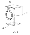
- Figure 8 is a perspective, partially see-through symbolical view similar of a further improved alternative embodiment of a machine according to the present invention;
- Figure 9 is a planar vertical and front cross-sectional view of the zone comprising said worktop and the portion lying therebelow, in a machine according to the present invention.
- With reference to Figure 1, a clothes washing machine according to the prior art comprises an
outer casing 1, which is delimited on top by ahorizontal worktop 2, while it is delimited by acontrol panel 4 on the upper front portion thereof. - Said control panel may be arranged so as illustrated in Figure 2, in which it is shown to substantially cover the whole upper front surface of the front wall of the outer casing and to join with the front edge of said worktop via a
juncture 6 extending vertically. It is readily apparent in this case that the two mutually facingedges 7 and 8 of the worktop and the control panel, respectively, are in a similar manner arranged along respective parallel, vertical planes. - Or said worktop may itself be arranged so as to extend frontally up to a point at which it covers the upper edge of the control panel, so that the
juncture 16 between the worktop and the control panel comes in this case to lie horizontally, so as this is shown in Figure 3. - As already mentioned, in both cases it may anyway occur that some liquid, such as typically the liquid dripping from wet clothes placed on the worktop or, for the matter, even any other kind of liquid being typically handled in the proximity of or in connection with the use of a washing machine, including the special low surface-tension liquid used to carry out the afore-mentioned dripping test provided for by the safety standard regulations, and sprayed with specially designed means onto the machine to that purpose, is able to seep through said
juncture - According to the present invention, and with reference to Figures 4 and 5, under the inner edge of said
juncture gutter 20, which clearly has a liquid collecting convexity facing, i.e. oriented upwards and aligned along the vertical of the contour of said inner edge of said juncture. - Basically, said
gutter 20 is so shaped and sized, and is so positioned, as to ensure that any liquid that may possibly seep through said juncture and drip down therefrom is reliably and effectively intercepted by and collected in said gutter, for being then removed or carried away in a manner that will be better explained further on in this description. - This
gutter 20 may be constituted by a specially provided, i.e. dedicated additional part to be installed with a specific assembly operation; however, given the fact that the material used to make said gutter and the sizing thereof are not critical factors, said gutter may also be made integral, i.e. as a unitary piece with either said worktop, so as shown in Figure 6, or said control panel, so as shown in Figure 7. - Or, anyway, even in the case that for any reason whatsoever it is not made integral with said parts of the machine, said gutter may be manufactured separately to be then applied in advance to the appropriate edges of said parts so that, when the worktop and the control panel are eventually assembled, the gutter itself is automatically brought into its intended position.
- With reference to Figure 6A, the case is illustrated in which a washing machine is provided with a
front crosspiece 30, as this occurs normally in the current practice whenever a clothes washing machine has a control panel extending for a short distance towards the worktop lying thereabove. In this case, it is a preferred option to appropriately process, i.e. form said crosspiece so as to shape its upper portion in the form of one of the above describedgutters 20. - Even in the case that the worktop extends to actually fully cover the machine, as illustrated in Figure 7A, the respective
front crosspiece 31, which most obviously cannot extend up to and within the worktop, may then be still advantageously shaped so as to form a respective upwards facinggutter 21 that comes to lie exactly underneath the inner end portion of therespective juncture 16, where - as it can be readily appreciated - liquid is most likely to possibly seep and drip. - In any case, the techniques needed to fabricate and assemble gutters of this kind are fully within the capabilities of those skilled in the art, so that no need arises here, actually, for them to be described and explained any further.
- The above-discussed gutter must anyway be made and provided so as to be able to be up to its task, which consists in preventing any liquid that may possibly seep through the juncture from being able to drip into and spread inside the washing machine. To such purpose, said gutter must be capable of safely carrying away the collected liquid for discharging it outside in a basically simple and spontaneous manner.
- This may of course be achieved in a number of ways. The simplest manner to do this basically consists in allowing the gutter to fill up, and therefore the level of the liquid collected therein to reach up to such value as to cause said liquid to overflow, for instance from the two opposite end portions of the gutter.
- As it flows over in this way, the liquid itself may be diverted, i.e. conveyed in any desired direction to be collected by or into any suitable means, provided that it is not conveyed or directed towards the electric circuits and parts of the machine.
- In particular, from said gutter there may be advantageously provided to depart appropriate drain channels, which are not specially shown in the Figures owing to them not being relevant to the purposes of the present invention, and which are adapted to allow the liquid collecting in said gutter to safely flow out.
- These drain channels may be such as to convey said liquid directly onto the floor on which the machine is resting. However, in order to avoid wetting or soiling the floor, the provision may advantageously be taken to allow said liquid to appropriately flow back into the same water-carrying circuit of the machine, which of course lies therebelow and, therefore, can be easily reached in a number of parts and/or fittings thereof.
- In particular, a solution in this connection may consist in allowing said liquid to be discharged into the lower drain sump of the washing tub, so as to avoid contaminating the washing/rinsing liquor contained in the same tub.
- This solution, however, has a drawback in that the drain conduit of said gutter must be water-tight at least along the lower portion thereof, so as to prevent the liquid contained therein from being able to again overflow and leak out into the machine owing to the principle of communicating vessels, as it is in direct communication with the washing/rinsing bath inside the tub.
- In view of avoiding such occurrence, and with reference to Figure 8, in washing machines provided with a
bottom pan 10 arranged immediately above the floor to collect possible water leakages from water-carrying parts and circuits located thereabove, use can be advantageously made of this facility to enable the liquid to directly flow from said gutter right down into said collectingpan 10 via anappropriate conduit 11. This solution would of course enable the need for special water-tight conduits and fittings to be done away with, while making it possible for a solution to be implemented, which is extremely simple, low-cost and reliable in its operation. - It may anyway still occur that, owing to the density of the liquid spilled onto said worktop of the machine, or even an insufficient amount of liquid actually dripping into the gutter, this liquid ends up by stagnating in the gutter itself and, as a result, cannot be discharged therefrom, thereby giving rise to well-known problems, such as bad odours, fermentations, and the like.
- In order to avoid such risk, and with reference to Figure 9, said gutter may advantageously be made, or positioned, so as to exhibit a downward inclination i relative to the horizontal plane H, so that one 24 of the end portions thereof comes to be positioned at a level l that is lower than the level L of the remaining part of the gutter and/or the
other end portion 25. This would facilitate the liquid that may possibly collect in the gutter to flow down by gravity towards saidlower end portion 24, so that it will not stagnate in the same gutter and will be discharged rapidly therefrom.
Claims (5)
- Front-loading clothes washing or drying machine comprising:- an outer casing (1),- a worktop (2) delimiting said outer casing at the top,- a facia or control panel (4) arranged on the upper front portion of said outer casing,in which said worktop and said control panel delimitate each other along respective edges (7, 8), which define a juncture (6, 16) extending vertically or horizontally, characterized in that underneath the inner end portion of said juncture there are arranged gutter-like means (20, 21) having an upward open convexity facing said juncture and, in particular, said inner end portion of said juncture, said gutter-like means extending substantially over the whole length of said juncture.
- Machine according to claim 1, characterized in that said gutter-like means (20) are provided as a unitary piece, i.e. integral with said worktop (2) or, alternatively, as a unitary piece, i.e. integral with said control panel (4).
- Machine according to claim 1, characterized in that it comprises an upper front crosspiece (30, 31) that is arranged between said control panel and said worktop, and that said gutter-like means (20, 21) are provided by suitably forming said upper front crosspiece into a corresponding shape.
- Machine according to any of the preceding claims, characterized in that it is provided with a bottom pan (10) arranged so as to be able to collect any possible leakage from parts of the water-carrying circuit of the machine, and that there is provided a suitable conduit (11) allowing for the liquid collected in said gutter-like means to flow off by gravity therefrom to be let out above and fall right into said bottom pan.
- Machine according to any of the preceding claims, characterized in that said gutter-like means (20, 21) are given a preferably continuous inclination (i) relative to a horizontal plane (H), so that an end portion (24) thereof comes to lie at a level (1) that is lower than the level (L) of the opposite end portion (25) thereof.
Priority Applications (5)
| Application Number | Priority Date | Filing Date | Title |
|---|---|---|---|
| EP04105038A EP1647624A1 (en) | 2004-10-14 | 2004-10-14 | Front-loading clothes washing machine with gutter arrangement on top |
| AU2005205815A AU2005205815A1 (en) | 2004-10-14 | 2005-09-05 | Front-loading clothes washing machine with a gutter arrangement on top |
| US11/225,545 US20060081015A1 (en) | 2004-10-14 | 2005-09-13 | Front-loading clothes washing machine with a gutter arrangement on top |
| BRPI0504200-3A BRPI0504200A (en) | 2004-10-14 | 2005-09-26 | front loading washer or dryer |
| JP2005298083A JP2006110352A (en) | 2004-10-14 | 2005-10-12 | Front-load laundry machine with drain on its top |
Applications Claiming Priority (1)
| Application Number | Priority Date | Filing Date | Title |
|---|---|---|---|
| EP04105038A EP1647624A1 (en) | 2004-10-14 | 2004-10-14 | Front-loading clothes washing machine with gutter arrangement on top |
Publications (1)
| Publication Number | Publication Date |
|---|---|
| EP1647624A1 true EP1647624A1 (en) | 2006-04-19 |
Family
ID=34929702
Family Applications (1)
| Application Number | Title | Priority Date | Filing Date |
|---|---|---|---|
| EP04105038A Withdrawn EP1647624A1 (en) | 2004-10-14 | 2004-10-14 | Front-loading clothes washing machine with gutter arrangement on top |
Country Status (5)
| Country | Link |
|---|---|
| US (1) | US20060081015A1 (en) |
| EP (1) | EP1647624A1 (en) |
| JP (1) | JP2006110352A (en) |
| AU (1) | AU2005205815A1 (en) |
| BR (1) | BRPI0504200A (en) |
Cited By (2)
| Publication number | Priority date | Publication date | Assignee | Title |
|---|---|---|---|---|
| KR100867121B1 (en) * | 2007-02-14 | 2008-11-06 | 삼성전자주식회사 | Drum type washing machine |
| EP2460454A3 (en) * | 2010-12-01 | 2017-06-14 | BSH Hausgeräte GmbH | Panel for a household appliance and household appliance |
Families Citing this family (11)
| Publication number | Priority date | Publication date | Assignee | Title |
|---|---|---|---|---|
| US7748243B2 (en) * | 2005-04-15 | 2010-07-06 | Lg Electronics Inc. | Washing machine |
| KR101263316B1 (en) * | 2006-05-30 | 2013-05-15 | 동부대우전자 주식회사 | Draining structure of washer |
| KR101416695B1 (en) * | 2007-05-07 | 2014-07-09 | 삼성전자 주식회사 | Washing machine |
| JP4821899B2 (en) * | 2009-09-10 | 2011-11-24 | パナソニック株式会社 | Drum washing machine |
| US11019738B2 (en) | 2019-01-21 | 2021-05-25 | Whirlpool Corporation | Laundry appliance |
| KR20210105683A (en) | 2020-02-19 | 2021-08-27 | 엘지전자 주식회사 | Laundry treating apparatus |
| US12049719B2 (en) | 2021-04-12 | 2024-07-30 | Whirlpool Corporation | Water intrusion protection for techframe and console |
| US12053134B2 (en) | 2021-08-12 | 2024-08-06 | Whirlpool Corporation | Dishwasher |
| USD1017934S1 (en) * | 2021-10-15 | 2024-03-12 | Lg Electronics Inc. | Electric drying machine for laundry purpose |
| USD1017149S1 (en) * | 2021-10-15 | 2024-03-05 | Lg Electronics Inc. | Electric drying machine for laundry purpose |
| USD1017159S1 (en) * | 2021-10-15 | 2024-03-05 | Lg Electronics Inc. | Electric washing machine |
Citations (6)
| Publication number | Priority date | Publication date | Assignee | Title |
|---|---|---|---|---|
| DE4104324A1 (en) * | 1991-02-13 | 1992-08-20 | Bosch Siemens Hausgeraete | Household washing machine or dishwasher - with cabinet-type housing with groove along wall to collect water leaking from inlet and lead it into collector |
| JPH08168588A (en) * | 1994-12-19 | 1996-07-02 | Toshiba Corp | Washing machine |
| DE19601124A1 (en) * | 1995-04-06 | 1996-10-10 | Miele & Cie | Cover panel for domestic appliances with core panel and plastic frame |
| DE19651821A1 (en) * | 1996-12-13 | 1998-06-18 | Miele & Cie | Washing machine, etc. |
| DE10101217A1 (en) * | 2001-01-12 | 2002-07-18 | Mecalit Gmbh | Domestic machine, e.g. a washing machine, has cover panel movably mounted on housing and able to be fixed by stops in end position guaranteeing flush butting with front of switch panel |
| WO2002090640A1 (en) * | 2001-05-04 | 2002-11-14 | Multibrâs S/A Electrodomèsticos | Clothes drying machine |
Family Cites Families (2)
| Publication number | Priority date | Publication date | Assignee | Title |
|---|---|---|---|---|
| DE19637742A1 (en) * | 1996-09-16 | 1998-03-19 | Bosch Siemens Hausgeraete | Household washing machine with pipes for the guidance of water and air |
| KR20040025139A (en) * | 2002-09-18 | 2004-03-24 | 엘지전자 주식회사 | structure of top cover in clothes dryer |
-
2004
- 2004-10-14 EP EP04105038A patent/EP1647624A1/en not_active Withdrawn
-
2005
- 2005-09-05 AU AU2005205815A patent/AU2005205815A1/en not_active Abandoned
- 2005-09-13 US US11/225,545 patent/US20060081015A1/en not_active Abandoned
- 2005-09-26 BR BRPI0504200-3A patent/BRPI0504200A/en not_active IP Right Cessation
- 2005-10-12 JP JP2005298083A patent/JP2006110352A/en active Pending
Patent Citations (6)
| Publication number | Priority date | Publication date | Assignee | Title |
|---|---|---|---|---|
| DE4104324A1 (en) * | 1991-02-13 | 1992-08-20 | Bosch Siemens Hausgeraete | Household washing machine or dishwasher - with cabinet-type housing with groove along wall to collect water leaking from inlet and lead it into collector |
| JPH08168588A (en) * | 1994-12-19 | 1996-07-02 | Toshiba Corp | Washing machine |
| DE19601124A1 (en) * | 1995-04-06 | 1996-10-10 | Miele & Cie | Cover panel for domestic appliances with core panel and plastic frame |
| DE19651821A1 (en) * | 1996-12-13 | 1998-06-18 | Miele & Cie | Washing machine, etc. |
| DE10101217A1 (en) * | 2001-01-12 | 2002-07-18 | Mecalit Gmbh | Domestic machine, e.g. a washing machine, has cover panel movably mounted on housing and able to be fixed by stops in end position guaranteeing flush butting with front of switch panel |
| WO2002090640A1 (en) * | 2001-05-04 | 2002-11-14 | Multibrâs S/A Electrodomèsticos | Clothes drying machine |
Non-Patent Citations (1)
| Title |
|---|
| PATENT ABSTRACTS OF JAPAN vol. 1996, no. 11 29 November 1996 (1996-11-29) * |
Cited By (2)
| Publication number | Priority date | Publication date | Assignee | Title |
|---|---|---|---|---|
| KR100867121B1 (en) * | 2007-02-14 | 2008-11-06 | 삼성전자주식회사 | Drum type washing machine |
| EP2460454A3 (en) * | 2010-12-01 | 2017-06-14 | BSH Hausgeräte GmbH | Panel for a household appliance and household appliance |
Also Published As
| Publication number | Publication date |
|---|---|
| BRPI0504200A (en) | 2006-06-27 |
| AU2005205815A1 (en) | 2006-05-04 |
| JP2006110352A (en) | 2006-04-27 |
| US20060081015A1 (en) | 2006-04-20 |
Similar Documents
| Publication | Publication Date | Title |
|---|---|---|
| US20060081015A1 (en) | Front-loading clothes washing machine with a gutter arrangement on top | |
| US20110131735A1 (en) | Washing machine and washing method | |
| EP1059058B1 (en) | Washing agents dispenser, in particular for diswashing machines | |
| US4413592A (en) | Water damage preventer pan | |
| TWI717172B (en) | Waterproof touch panel device | |
| CN209032242U (en) | Frame assembly and dish-washing machine | |
| KR101241866B1 (en) | Dish washer | |
| US6574996B1 (en) | Tub sump dam | |
| CN106618164A (en) | Cooking utensil | |
| WO2011009777A1 (en) | Water-bearing household appliance | |
| PL197055B1 (en) | Tray for entrapping leakage water from household appliances | |
| US4061002A (en) | Motor shield for appliance | |
| EP3983597B1 (en) | A household appliance having a top plate | |
| CN209032245U (en) | Liner component and dish-washing machine | |
| WO2020220939A1 (en) | Upper cover of clothing treatment equipment and clothing treatment equipment | |
| CN114808367B (en) | Clothes treating apparatus | |
| US2919568A (en) | Strainer for drain of a clothes washer | |
| EP2860302B1 (en) | Laundry treatment machine | |
| KR0124876Y1 (en) | Washing machine with detecting device for detergent | |
| CN218096101U (en) | Oil discharge device and integrated stove | |
| CN217792491U (en) | Cooking utensil | |
| KR101263316B1 (en) | Draining structure of washer | |
| CN209951036U (en) | Edge water leakage structure of cooking surface of water cooking stove | |
| CN206773571U (en) | Kitchen appliance | |
| KR970002813Y1 (en) | Dishwasher |
Legal Events
| Date | Code | Title | Description |
|---|---|---|---|
| PUAI | Public reference made under article 153(3) epc to a published international application that has entered the european phase |
Free format text: ORIGINAL CODE: 0009012 |
|
| AK | Designated contracting states |
Kind code of ref document: A1 Designated state(s): AT BE BG CH CY CZ DE DK EE ES FI FR GB GR HU IE IT LI LU MC NL PL PT RO SE SI SK TR |
|
| AX | Request for extension of the european patent |
Extension state: AL HR LT LV MK |
|
| AKX | Designation fees paid |
Designated state(s): AT BE BG CH CY CZ DE DK EE ES FI FR GB GR HU IE IT LI LU MC NL PL PT RO SE SI SK TR |
|
| STAA | Information on the status of an ep patent application or granted ep patent |
Free format text: STATUS: THE APPLICATION IS DEEMED TO BE WITHDRAWN |
|
| 18D | Application deemed to be withdrawn |
Effective date: 20061020 |