EP1647299A2 - Verstellbarer Ballonkatheter und Verfahren zur Herstellung der relativen Lage von verschiedenen Ballonen des Katheters in einem Körperkanal - Google Patents
Verstellbarer Ballonkatheter und Verfahren zur Herstellung der relativen Lage von verschiedenen Ballonen des Katheters in einem Körperkanal Download PDFInfo
- Publication number
- EP1647299A2 EP1647299A2 EP05026310A EP05026310A EP1647299A2 EP 1647299 A2 EP1647299 A2 EP 1647299A2 EP 05026310 A EP05026310 A EP 05026310A EP 05026310 A EP05026310 A EP 05026310A EP 1647299 A2 EP1647299 A2 EP 1647299A2
- Authority
- EP
- European Patent Office
- Prior art keywords
- shaft
- inflatable
- catheter
- moveable
- disposed
- Prior art date
- Legal status (The legal status is an assumption and is not a legal conclusion. Google has not performed a legal analysis and makes no representation as to the accuracy of the status listed.)
- Withdrawn
Links
- 238000000034 method Methods 0.000 title abstract description 16
- 239000012530 fluid Substances 0.000 claims description 45
- 239000003550 marker Substances 0.000 claims description 5
- 238000003780 insertion Methods 0.000 claims description 3
- 230000037431 insertion Effects 0.000 claims description 3
- 238000004891 communication Methods 0.000 description 4
- 210000001367 artery Anatomy 0.000 description 3
- 239000007943 implant Substances 0.000 description 3
- 238000001356 surgical procedure Methods 0.000 description 3
- 210000000626 ureter Anatomy 0.000 description 3
- 210000001124 body fluid Anatomy 0.000 description 2
- 239000010839 body fluid Substances 0.000 description 2
- 238000010276 construction Methods 0.000 description 2
- 238000003384 imaging method Methods 0.000 description 2
- 208000014674 injury Diseases 0.000 description 2
- 238000012986 modification Methods 0.000 description 2
- 230000004048 modification Effects 0.000 description 2
- 238000007789 sealing Methods 0.000 description 2
- 208000009087 False Aneurysm Diseases 0.000 description 1
- 206010016717 Fistula Diseases 0.000 description 1
- 208000027418 Wounds and injury Diseases 0.000 description 1
- 208000002223 abdominal aortic aneurysm Diseases 0.000 description 1
- 238000011161 development Methods 0.000 description 1
- 230000000916 dilatatory effect Effects 0.000 description 1
- 238000002224 dissection Methods 0.000 description 1
- 230000003890 fistula Effects 0.000 description 1
- 239000000463 material Substances 0.000 description 1
- 238000012544 monitoring process Methods 0.000 description 1
- 230000002787 reinforcement Effects 0.000 description 1
- 230000003014 reinforcing effect Effects 0.000 description 1
Images


Classifications
-
- A—HUMAN NECESSITIES
- A61—MEDICAL OR VETERINARY SCIENCE; HYGIENE
- A61M—DEVICES FOR INTRODUCING MEDIA INTO, OR ONTO, THE BODY; DEVICES FOR TRANSDUCING BODY MEDIA OR FOR TAKING MEDIA FROM THE BODY; DEVICES FOR PRODUCING OR ENDING SLEEP OR STUPOR
- A61M25/00—Catheters; Hollow probes
- A61M25/10—Balloon catheters
- A61M25/1006—Balloons formed between concentric tubes
-
- A—HUMAN NECESSITIES
- A61—MEDICAL OR VETERINARY SCIENCE; HYGIENE
- A61F—FILTERS IMPLANTABLE INTO BLOOD VESSELS; PROSTHESES; DEVICES PROVIDING PATENCY TO, OR PREVENTING COLLAPSING OF, TUBULAR STRUCTURES OF THE BODY, e.g. STENTS; ORTHOPAEDIC, NURSING OR CONTRACEPTIVE DEVICES; FOMENTATION; TREATMENT OR PROTECTION OF EYES OR EARS; BANDAGES, DRESSINGS OR ABSORBENT PADS; FIRST-AID KITS
- A61F2/00—Filters implantable into blood vessels; Prostheses, i.e. artificial substitutes or replacements for parts of the body; Appliances for connecting them with the body; Devices providing patency to, or preventing collapsing of, tubular structures of the body, e.g. stents
- A61F2/95—Instruments specially adapted for placement or removal of stents or stent-grafts
- A61F2/958—Inflatable balloons for placing stents or stent-grafts
-
- A—HUMAN NECESSITIES
- A61—MEDICAL OR VETERINARY SCIENCE; HYGIENE
- A61M—DEVICES FOR INTRODUCING MEDIA INTO, OR ONTO, THE BODY; DEVICES FOR TRANSDUCING BODY MEDIA OR FOR TAKING MEDIA FROM THE BODY; DEVICES FOR PRODUCING OR ENDING SLEEP OR STUPOR
- A61M25/00—Catheters; Hollow probes
- A61M25/10—Balloon catheters
- A61M25/1011—Multiple balloon catheters
-
- A—HUMAN NECESSITIES
- A61—MEDICAL OR VETERINARY SCIENCE; HYGIENE
- A61M—DEVICES FOR INTRODUCING MEDIA INTO, OR ONTO, THE BODY; DEVICES FOR TRANSDUCING BODY MEDIA OR FOR TAKING MEDIA FROM THE BODY; DEVICES FOR PRODUCING OR ENDING SLEEP OR STUPOR
- A61M25/00—Catheters; Hollow probes
- A61M25/10—Balloon catheters
- A61M25/1025—Connections between catheter tubes and inflation tubes
-
- A—HUMAN NECESSITIES
- A61—MEDICAL OR VETERINARY SCIENCE; HYGIENE
- A61F—FILTERS IMPLANTABLE INTO BLOOD VESSELS; PROSTHESES; DEVICES PROVIDING PATENCY TO, OR PREVENTING COLLAPSING OF, TUBULAR STRUCTURES OF THE BODY, e.g. STENTS; ORTHOPAEDIC, NURSING OR CONTRACEPTIVE DEVICES; FOMENTATION; TREATMENT OR PROTECTION OF EYES OR EARS; BANDAGES, DRESSINGS OR ABSORBENT PADS; FIRST-AID KITS
- A61F2/00—Filters implantable into blood vessels; Prostheses, i.e. artificial substitutes or replacements for parts of the body; Appliances for connecting them with the body; Devices providing patency to, or preventing collapsing of, tubular structures of the body, e.g. stents
- A61F2/82—Devices providing patency to, or preventing collapsing of, tubular structures of the body, e.g. stents
- A61F2002/826—Devices providing patency to, or preventing collapsing of, tubular structures of the body, e.g. stents more than one stent being applied sequentially
-
- A—HUMAN NECESSITIES
- A61—MEDICAL OR VETERINARY SCIENCE; HYGIENE
- A61M—DEVICES FOR INTRODUCING MEDIA INTO, OR ONTO, THE BODY; DEVICES FOR TRANSDUCING BODY MEDIA OR FOR TAKING MEDIA FROM THE BODY; DEVICES FOR PRODUCING OR ENDING SLEEP OR STUPOR
- A61M25/00—Catheters; Hollow probes
- A61M25/10—Balloon catheters
- A61M25/1011—Multiple balloon catheters
- A61M2025/1015—Multiple balloon catheters having two or more independently movable balloons where the distance between the balloons can be adjusted, e.g. two balloon catheters concentric to each other forming an adjustable multiple balloon catheter system
Definitions
- the invention relates to an adjustable catheter having multiple inflatable portions, and' a method for varying the position of at least one inflatable portion of a catheter with respect to another inflatable portion of the catheter while the catheter is in a body passageway.
- catheters having inflatable portions, or balloons are used to expand body passageways such as arteries and ureters, for the removal of blockages or other surgical procedures.
- Balloon catheters are also used to implant prostheses, or grafts, in arteries, ureters and other body passageways.
- the inflatable portion, or balloon, of a catheter is used to expand and deform an attachment device or securing means, disposed on the balloon and associated with the prosthesis, by subjecting the attachment device or securing means to expansion forces by inflation of the balloon.
- the attachment device and prosthesis Upon deflation of the balloon and removal of the catheter, the attachment device and prosthesis remain anchored to the internal wall of the body passageway.
- a conventional procedure is known for viewing the position of catheter balloons while the catheter is disposed in a body passageway, such as with an x-ray device or fluoroscope.
- the predetermined, fixed distance between the catheter balloons may not reflect the ideal, or desired, distance determined while the catheter is viewed in the body passageway between the attachment devices carried on the balloons.
- the catheter must be completely removed from the body passageway and the distance between the balloons readjusted or the catheter replaced with a catheter having a pre-determined distance between inflatable portions that more closely matches the desired distance; or the attachment devices and prosthesis may be implanted without accurate spacing.
- the art has sought a multi-balloon catheter and method for adjusting the distance between multiple balloons of a multi-balloon catheter which are believed to: be time and cost efficient; provide precise adjustment and placement of multiple balloons and attachment devices to secure a prosthesis within a body passageway; and not require the removal of the catheter for adjustment of the distance between balloons.
- the present invention includes a catheter for insertion into a body passageway, including: a shaft having first and second ends and a longitudinal axis extending therebetween; first and second inflatable members disposed on the shaft along the longitudinal axis of the shaft; and means for adjusting the position of at least one of the first and second inflatable members along the longitudinal axis of the shaft while the catheter is disposed within the body passageway.
- the shaft may include a first passage disposed in fluid transmitting relationship with the first inflatable member to allow the first inflatable member to be expanded upon the introduction of a fluid into the first passage.
- the first and second inflatable members may be first and second inflatable balloons.
- the adjusting means may be first and second moveable members that are: disposed on the shaft between the first inflatable member and the second end of the shaft; associated with each other by a connection means to allow their cooperative movement along the longitudinal axis of the shaft; and which carry the second inflatable member attached to the first moveable member at its first end and to the second moveable member at its second end.
- the first and second moveable members may be spaced from each other to form an annular clearance disposed between the first and second moveable members, the annular clearance being in fluid transmitting relationship with the second inflatable member so that the second inflatable member may be expanded upon the introduction of fluid into the annular clearance.
- the adjusting means of the present invention may take the form of an alternate embodiment that includes a single moveable member that: is disposed upon the shaft of the catheter for movement along the longitudinal axis of the shaft; carries the second inflatable member; includes a second passage disposed in fluid transmitting relationship with the second inflatable member to allow the second inflatable member to be expanded upon the introduction of a fluid into the second passage; and is moveable with respect to the first inflatable member.
- This aspect of the present invention may include: a catheter, having first and second inflatable members disposed upon its shaft along the longitudinal axis of the shaft; a first securing means disposed upon the first inflatable member; a second securing means disposed upon the second inflatable member; a prosthesis having first and second ends, whereby the first securing means is attached to the prosthesis proximate the first end of the prosthesis and the second securing means is associated with the prosthesis proximate the second end of the prosthesis; and means for adjusting the location of the second inflatable member with respect to the first inflatable member along the longitudinal axis of the shaft.
- the first and second securing means may be expandable tubular shaped members.
- the foregoing advantages have also been achieved through the present method for adjusting the position of at least one of the inflatable portions of a catheter while the catheter is located in a body passageway.
- the method of the present invention may include the steps of: disposing the catheter in the body passageway; positioning the first inflatable member of the catheter in the body passageway at a desired location; and moving the moveable means of the catheter relative the shaft of the catheter along the longitudinal axis of the shaft to selectively position the second inflatable portion of the catheter with respect to the first inflatable portion.
- Another aspect of the present invention is a method for adjusting the position of at least one of the inflatable portions of a catheter while the catheter is located in the body passageway to implant, within the body passageway, a prosthesis carried upon the catheter.
- This aspect of the present invention may include the steps of: providing a first securing means for the first end of the prosthesis; providing the first securing means and the first end of the prosthesis on the first inflatable portion of the catheter; providing a second securing means on the second inflatable portion of the catheter; disposing the catheter, first securing means and prosthesis within the body passageway; positioning the first inflatable portion of the catheter, first securing means and first end of the prosthesis within the body passageway at a desired location; and moving the second inflatable portion of the catheter with respect to the first inflatable portion.
- a further feature of this aspect of the present invention may include the steps of inflating the first inflatable portion to expand the first securing means, causing the first securing means and first end of the prosthesis to be secured within the body passageway.
- This aspect of the present invention may include the further steps of positioning the second inflatable portion of the catheter at a desired location within the prosthesis and inflating the second inflatable portion to expand the second securing means, securing the second securing means and prosthesis within the body passageway.
- An additional feature of the present method may include the steps of: providing at least one moveable member disposed on the catheter; disposing the second inflatable portion of the catheter onto the at least one moveable member; and positioning the second inflatable portion at a desired location within the body passageway by moving the at least one moveable member relative the first inflatable portion of the catheter after the first inflatable portion is positioned within the body passageway.
- a final feature of this aspect of the present invention may include the further steps of inflating the second inflatable member to expand the second securing means and secure the second securing means and prosthesis within the body passageway, deflating the first inflatable member, deflating the second inflatable member, and removing the catheter from the body passageway.
- the adjustable inflatable catheter and method for adjusting the relative position of multiple inflatable portions of a catheter within a body passageway of the present invention when compared with previously proposed prior art devices and methods, are believed to have the advantages of: being time and cost efficient; providing precise adjustment and placement of multiple balloons and attachment devices to secure a prosthesis to a body passageway; and not requiring the removal of the catheter for adjustment of the distance between adjacent balloons of a multi-balloon catheter.
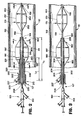
- FIGS. 1-3 illustrate a catheter 150 for expanding a body passageway 151 or implanting a prosthesis, or graft, (350, FIG. 9) in the body passageway 151 at a desired location 152.
- catheter 150 includes a shaft 154 having first and second ends 156 , 157 , respectively, and a longitudinal axis 158 extending therebetween.
- the first end 156 of the shaft 154 is located at the distal end of the catheter and is to be inserted into the body passageway 151 and the second end 157 of the shaft 154 is located at the proximal end of the catheter 150 .
- any number of inflatable members may be disposed upon the shaft 154.
- shaft 154 is shown in FIGS. 1-3 to have first and second inflatable members 170 and 180, respectively, disposed about its longitudinal axis 158.
- the inflatable members 170, 180 may be of any known type of inflatable member suitable for use in connection with catheters, such as balloons 170', 180' (FIGS. 2 and 3).
- the inflatable members 170, 180, or balloons 170', 180' may be of any shape, as long as they have the requisite strength and flexibility to be inflated and deflated, and are capable of expanding and deforming a means for securing a prosthesis within a body passageway as will be hereinafter described in further detail.
- the first inflatable member 170, or balloon 170' is disposed upon the shaft 154 proximate the first end 156 of the shaft 154.
- the second inflatable member 180, or balloon 180', having first and second ends 182, 183 and 182', 183', respectively, is disposed upon the shaft 154 between the first inflatable member 170, or balloon 170', and the second end 157 of 'the shaft 154.
- the shaft 154 of catheter 150 may include a plurality of internal passages.
- FIGS. 4-6 illustrate shaft 154 having three internal passages 190, 191 and 192, each extending through the shaft 154 along the longitudinal axis 158 of the shaft 154.
- One of the plurality of internal passages of the shaft 154 may be utilized to provide a passage, or lumen, for a conventional guide wire, or mandrel.
- FIG. 1 illustrates guide wire 162 extending through the passage 190 (FIGS. 4-6) of the shaft 154.
- the guide wire 162 is preferably of standard construction and may exit the shaft 154 through a conventional nosepiece 159.
- Another passage among the plurality of internal passages of the shaft 154 may be used to allow the introduction of a fluid into one of the inflatable members disposed on the shaft 154 from an outside source through an inlet port associated with the shaft 154 to allow such inflatable member to be selectively inflated and deflated.
- Each inflatable member may thus each be disposed on the shaft 154 in fluid transmitting relationship with at least one internal passage of the shaft 154 .
- the first inflatable member 170 or balloon 170' may be disposed in fluid communication with internal passage 191 (FIG. 4), which is in fluid communication with an inlet port 193 (FIG. 1).
- a suitable fluid may be provided into the inlet port 193 in a conventional manner from an outside source (not shown).
- the catheter 150 includes means for adjusting the position of at least one of the plurality of inflatable members along the longitudinal axis 158 of the shaft 154 relative the shaft 154 while the catheter 150 is disposed in the body passageway 151.
- the catheter 150 includes means for adjusting 200 the position.of the second inflatable member 180 relative to the shaft 154 and first inflatable member 170 along the longitudinal axis 158 of the shaft 154 .
- FIGS. 2 and 4-6 illustrates a preferred embodiment of the means for adjusting 200 the position of the second inflatable member 180 , or balloon 180' , which includes first and second moveable tubular members 210 and 220 .
- the first moveable member 210 has first and second ends 211 and 212, respectively, and the second moveable member 220 has first and second ends 221 and 222, respectively.
- the first moveable member 210 has a friction fit upon shaft 154 , whereby the internal diameter of first moveable member 210 closely conforms, in a sealing relationship, with the outer wall surface of shaft 154.
- the first and second movable members 210, 220 may be associated in a manner which allows their cooperative movement with respect to the shaft 154 along the longitudinal axis 158 of the shaft 154.
- the moveable members 210, 220 may be associated proximate their second ends 212, 222, by connection means 230, which connects the first and second moveable member 210, 220 to each other.
- the connection means 230 is illustrated by a Y-connector 232, which connects first and second moveable members 210, 220 proximate their respective second ends 212, 222 and includes an annulus 234 through which the shaft 154 passes to allow cooperative, slidable, movement of the Y-connector 232 and moveable members 210, 220 over the shaft 154 along its longitudinal axis 158.
- the second inflatable member 180, or balloon 180' is secured to the means for adjusting 200 the position of the second inflatable member 180, or balloon 180', to allow the second inflatable member 180, or balloon 180', to be moveable relative the first inflatable member 170, or balloon 170', along the longitudinal axis 158 of the shaft 154.
- the first end 182' of the second balloon 180' may be secured to the first moveable member 210 proximate its first end 211 and the second end 183' of the second balloon 180' may be secured to the second movable member 220 proximate its first end 221 .
- the location of the second inflatable member 180, or balloon 180' may be adjusted with respect to the first inflatable member 170 or balloon 170'.
- FIGS. 2 and 4 illustrate an annular clearance 226 formed between the first and second movable members 210, 220. Fluid may be introduced into the annular clearance 226 through an inlet port 227.
- the annular clearance 226 opens into the second inflatable member 180 or balloon 180' as a result of the length L 1 of the first moveable member 210 being greater than the length L 2 of the second movable member 220, allowing the annular clearance 226 to be in fluid communicating relationship with the second balloon 180'.
- connection means 200 upon controlled movement of the connection means 200 from outside the body, which in turn simultaneously moves the first and second moveable tubular members 210, 220, the location of the second inflatable member 180, or balloon 180', with respect to the first inflatable member 170, or balloon 170', may be adjusted along the longitudinal axis 158 of the shaft 154.
- the inflatable members 170, 180, or balloons 170', 180' may be expanded upon the introduction of a fluid into entry ports 19.3, 227 and through passage 191 (FIG. 5) and clearance 226, respectively, in a conventional manner.
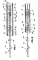
- FIG. 3 illustrates an alternate embodiment of the means for adjusting 200 , which includes a single moveable tubular member 202 , upon which the second inflatable member 180, or balloon 180' is disposed.
- Moveable member 202 is slidably moveable upon the shaft 154 along the longitudinal axis 158 of the shaft 154 relative to the shaft 154 and first inflatable member 170 , or balloon 170' .
- the moveable member 202 is disposed about, and has a friction fit about, the shaft 154, as previously described in connection with FIG. 2.
- the moveable member 202 may include a passage for the introduction of fluid into the second balloon 180' for inflation and deflation of the second balloon 180'.
- FIG. 3 illustrates an alternate embodiment of the means for adjusting 200 , which includes a single moveable tubular member 202 , upon which the second inflatable member 180, or balloon 180' is disposed.
- Moveable member 202 is slidably moveable upon the shaft 154 along the longitudinal axis 158 of the shaft 154 relative
- FIG. 2 illustrates a passage 204 formed between the moveable member 202 and shaft 154, seals 205 and 206 at each end of the moveable member 202, and fluid entry and exit ports, 207 and 208; respectively, for the introduction of fluid into the passage 204 and second balloon 180' from an outside source.
- Radiopaque markers may be attached to the catheter 150 at predetermined, select locations to allow the location of the catheter 150 and the inflatable members 170, 180 to be monitored with the use of a fluoroscope or x-ray device while the catheter 150 is in the body passageway 151.
- FIG. 3 illustrates the use of a first pair of radiopaque markers 252 disposed on the shaft 154 proximate the first balloon 170' and a second pair of radiopaque markers 254 disposed on the first movable member 210 proximate the second balloon 180' for monitoring the position of the first and second balloons 170', 180' in the body passageway 151.
- the catheter 150 of the present invention may include a prosthesis, or graft, 350 and means for securing 300 the prosthesis 350 within the body passageway 151.
- a securing means 300 is preferably attached to each end of the prosthesis 350 and is preferably disposed on at least one inflatable member of the catheter 150 for delivery into the body passageway 151, and to anchor the prosthesis 350 to the interior wall 153 of the body passageway 151.
- the prosthesis 350 provides a passageway 360 (FIG. 10) through the body passageway 151 so that the body fluid flowing through the body passageway 151 can pass through the location of the prosthesis 350, such as a location 152 of repair or reinforcement.
- the prosthesis 350 may be a tubular graft having first and second ends 354, 356 and a flexible wall 358 disposed therebetween, the graft 350 adapted to be disposed within the body passageway 151 , such as the graft described in U.S. Patent No. 5,360,443, issued November 1, 1994, and incorporated herein by reference.
- Each securing means 300 may be at least one expandable tubular shaped member 302.
- any known type of intraluminally deliverable expandable member 302 could be utilized as securing means 300 provided it has the ability to be secured to a prosthesis and carried on an inflatable member of a catheter and expanded from a first diameter D 1 , which permits intraluminal delivery of the expandable member 302, to a second expanded D 2 , in order to secure the expandable member 302 and prosthesis 350 to the interior wall 153 of the body passageway 151 (FIGS. 7 and 8).
- An example of an expandable tubular shaped member 302 suitable for use in the present invention is shown in U.S. Patent No. 4,773,665, issued March 29, 1988, incorporated herein by reference.
- FIG. 8 illustrates a prosthesis, or graft, 350 and first securing means 310 associated with the first end 354 of the graft 350 and releasably mounted onto the first inflatable member 170 and a second securing means 320 associated with the second end 356 of the graft 350 and releasably mounted onto the second inflatable member 180 for delivery into the body passageway 151.
- the first and second securing means 310, 320 may be associated with the first and second ends 354, 356 of the prosthesis 350 in any suitable manner, such as by small sutures.
- the second securing means 320 may be releasably mounted on the second inflatable member 180 without being attached to the prosthesis 350, such that the second securing means 320 becomes associated with the prosthesis 350 at a desired location within the prosthesis 350 when the second inflatable member 180 is inflated.
- the securing means 300 may be releasably mounted upon the inflatable members 170, 180 of catheter 150 in any suitable fashion, whereby upon inflation of the inflatable members 170, 180 , the securing means 300 is forced radially outwardly into contact with the interior wall 1 53 of the body passageway 151 and the interior wall of the prosthesis, or graft, 350 .
- the prosthesis 350 and securing means 300 are disposed on the catheter 150 by passing the catheter 150 through the prosthesis 350 and securing means 300, such that the securing means 300 are disposed on the inflatable members 170, 180 of the catheter 150 and the prosthesis 350 extends therebetween.
- the catheter 150 as illustrated in FIG. 7, is in the configuration it would have for intraluminal delivery.
- the first and second securing means 310, 320 have their first unexpanded, undeformed diameter D 1 , and first and second inflatable members 170, 180 are shown completely deflated.
- catheter 150, first and second securing means 310, 320, and prosthesis 350 are preferably enclosed by a conventional delivery sheath 246 (FIG.
- a third inflatable member 240 or balloon tip 252 may be disposed on the shaft 154 between the first inflatable member 170 and the first end 156 of the shaft 154 for sealing the end of the delivery sheath 246 to prevent body fluid from entering the sheath 246 and disturbing the integrity and positioning of the first and second inflatable members 170, 180, prosthesis 350 and securing means 300 .
- the third inflatable member 240 , or balloon tip 242 may be in fluid communication with one of the passages of the shaft 154, such as passage 192 (FIGS. 4-6) which is in fluid communication with inlet port 244 for inflation and deflation of the balloon tip 242.
- FIGS. 8-10 illustrate catheter 150 in use for implanting a prosthesis 350 in a body passageway 151 .
- the catheter 150, prosthesis 350 and securing means 300 may be intraluminally delivered to the desired location 152 within the body passageway 151 and the sheath 246 withdrawn in a conventional manner.
- the inflatable portions 170, 180 are expanded to expand the securing means 300 to a desired diameter
- the prosthesis 350 opens and has a diameter substantially equal to the diameter D 2 of the securing means 300 , as shown in FIGS. 8 and 9.
- Expansion and deformation of the first and second securing means 310, 320 is accomplished by the expansion of first and second inflatable members 170, 180 of catheter 150 , in a conventional manner.
- Such expansion of the inflatable members 170, 180 may be accomplished independently or simultaneously or independently as desired and controlled by an operator.
- FIG. 8 illustrates first inflatable member 170 inflated and first securing means 310 in its expanded configuration having diameter D 2 .
- First securing means 310 and the first end 354 of prosthesis 350 are shown urged against the interior wall 153 of the body passageway 151.
- FIG. 9 illustrates both first and second inflatable members 170, 180 inflated and first and second securing means 310, 320 in an expanded configuration having diameters D 2.
- Deflation of inflatable members 170, 180 permits release of the inflatable members 170, 180 and catheter 150 from the body passageway 151 and prosthesis 350, after the prosthesis 350 and first and second securing means 310, 320 have been expanded and anchored to the interior wall 153 of the body passageway 151.
- the body passageway 151, graft 350, and securing means 300 have the configuration shown in FIG. 10.
- the catheter 150 of the present invention may similarly be used without a prosthesis and securing means for other purposes.
- a method, for use with a catheter 150 having at least first and second inflatable portions 170, 180, for adjusting the position of at least one of the inflatable portions while the catheter 150 is located in a body passageway 151 will now be described.
- the catheter 150 as described with respect to FIGS. 1-3 above, includes a shaft 154, and moveable means 200 disposed on the shaft 154 for relative movement along the longitudinal axis 158 of the shaft 154.
- the first inflatable portion 170 is disposed on the shaft 154 and the second inflatable portion 180 is disposed on moveable means 200 .
- the catheter 150 is disposed in the body passageway 151.
- the first inflatable member 170 is then positioned in the body passageway 151 at a desired location by controllably moving the catheter 1 50.
- the second inflatable portion 180 may be selectively positioned with respect to the first inflatable portion 170 by moving the moveable means 200 relative the shaft 154 along the longitudinal axis 158 of the shaft 154.
- the first and second inflatable portions 170, 180 may be controllably inflated, as previously described, in order to urge the inflatable portions 170, 180 against the interior wall 153 of the body passageway 151 .
- FIGS. 7-10 a method for adjusting the position of at least one inflatable portion of a catheter 150, having at least two inflatable portions, while the catheter 150 is disposed in a body passageway 151 to implant a prosthesis 350 carried on the catheter 150 will be described.
- the catheter 150 as described above with reference to FIGS. 1-6, would initially have first and second inflatable members 170, 180 or balloons 170', 180' uninflated, with the inflatable members 170, 180 or balloons 170', 180' disposed with respect to catheter 150 in a conventional manner to permit intraluminal delivery of the catheter 150 (Fig. 7).
- a first securing means 310 would be associated with first inflatable member 170, and a second securing means 320 would be associated with the second inflatable member 180.
- the prosthesis 350 could be attached at its ends to the securing means 310, 320 and extend therebetween, or be attached only at its first end 354 to first securing means 310.
- the delivery sheath 246 would then be disposed about catheter 150, and the catheter 150 delivered into the body passageway 151. Thereafter, the delivery sheath 246 is withdrawn in a conventional manner.
- the first inflatable member 170 With a conventional intraluminal imaging technique, such as with the use of a fluoroscope or x-ray device, to view the radiopaque marker or markers 252 disposed in the proximity of the first inflatable member 170, the first inflatable member 170, upon which the first securing means 310 and first end 354 of the prosthesis 350 is disposed, may be positioned at the desired location in the body passageway 151 . As shown in FIG. 8, the first inflatable member 170 may be controllably inflated, as previously described, to expand the first securing means 310 and anchor the first securing means 310 and first end 354 of the prosthesis 350 to the interior wall 153 of the body passageway 151.
- the second inflatable member 180, second securing means 320, and second end 356 of the prosthesis 350 may be selectively positioned in the body passageway 151 relative the first inflatable member 170 by moving the means for adjusting 200, the position of the second inflatable member 180 relative the shaft 154 .
- the use of a similar imaging technique as described above would allow the location of the radiopaque members 254 and second inflatable member 180 to be viewed. If the second securing means 320 is attached to the prosthesis 350, the prosthesis 350 will stretch sufficiently to allow its cooperative movement with the second securing means 320, as the second inflatable member 180 is moved.
- the second inflatable member 180 will be moved within the prosthesis 350 along the longitudinal axis 156 of the shaft 154.
- the second inflatable member 180 may be inflated to expand the second securing means 320 and anchor the second securing means 320 and prosthesis 350 against the interior wall 153 of the body passageway 151 (FIG. 9).
- the inflatable members 170, 180 may be inflated and deflated simultaneously or independently as desired.
- the first and second securing means 310, 320 and prosthesis 350 will remain anchored within the body passageway 151 after the first and second inflatable members 170, 180 are deflated and the catheter 150 is removed from the body passageway 151 .
- the catheter 150 of the present invention thus allows the selective and precise positioning of the second securing means 320 and second end 356 of the prosthesis 350 within the body passageway 151 relative to the position of the first securing means 310 and first end 354 of the prosthesis 350.
- the catheter 150 of the present invention and method of positioning multiple inflatable portions of the catheter 150 in the body passageway 151 are believed to be useful to expand, repair or reinforce numerous types of body passageways including abdominal aortic aneurysms, arterial venous fistulas, false aneurysms, dissection procedures, trauma-injury of arteries, and ureters, as well as to provide internal bypasses.
- the catheter could be provided with three inflatable portions, at least one of which may be moveable relative the other inflatable portions. Accordingly, the invention is therefore to be limited only by the scope of the appended claims.
Landscapes
- Health & Medical Sciences (AREA)
- Heart & Thoracic Surgery (AREA)
- Life Sciences & Earth Sciences (AREA)
- Engineering & Computer Science (AREA)
- Biomedical Technology (AREA)
- Animal Behavior & Ethology (AREA)
- Veterinary Medicine (AREA)
- Public Health (AREA)
- General Health & Medical Sciences (AREA)
- Pulmonology (AREA)
- Child & Adolescent Psychology (AREA)
- Biophysics (AREA)
- Anesthesiology (AREA)
- Hematology (AREA)
- Vascular Medicine (AREA)
- Transplantation (AREA)
- Oral & Maxillofacial Surgery (AREA)
- Cardiology (AREA)
- Media Introduction/Drainage Providing Device (AREA)
- Prostheses (AREA)
Applications Claiming Priority (2)
| Application Number | Priority Date | Filing Date | Title |
|---|---|---|---|
| US08/475,755 US5820595A (en) | 1995-06-07 | 1995-06-07 | Adjustable inflatable catheter and method for adjusting the relative position of multiple inflatable portions of a catheter within a body passageway |
| EP96304143A EP0747088B1 (de) | 1995-06-07 | 1996-06-05 | Verstellbarer Ballonkatheter |
Related Parent Applications (1)
| Application Number | Title | Priority Date | Filing Date |
|---|---|---|---|
| EP96304143A Division EP0747088B1 (de) | 1995-06-07 | 1996-06-05 | Verstellbarer Ballonkatheter |
Publications (2)
| Publication Number | Publication Date |
|---|---|
| EP1647299A2 true EP1647299A2 (de) | 2006-04-19 |
| EP1647299A3 EP1647299A3 (de) | 2006-09-27 |
Family
ID=23888981
Family Applications (2)
| Application Number | Title | Priority Date | Filing Date |
|---|---|---|---|
| EP96304143A Expired - Lifetime EP0747088B1 (de) | 1995-06-07 | 1996-06-05 | Verstellbarer Ballonkatheter |
| EP05026310A Withdrawn EP1647299A3 (de) | 1995-06-07 | 1996-06-05 | Verstellbarer Ballonkatheter und Verfahren zur Herstellung der relativen Lage von verschiedenen Ballonen des Katheters in einem Körperkanal |
Family Applications Before (1)
| Application Number | Title | Priority Date | Filing Date |
|---|---|---|---|
| EP96304143A Expired - Lifetime EP0747088B1 (de) | 1995-06-07 | 1996-06-05 | Verstellbarer Ballonkatheter |
Country Status (9)
| Country | Link |
|---|---|
| US (1) | US5820595A (de) |
| EP (2) | EP0747088B1 (de) |
| JP (1) | JP3874034B2 (de) |
| KR (1) | KR100317970B1 (de) |
| AR (1) | AR002317A1 (de) |
| AU (1) | AU713038B2 (de) |
| CA (1) | CA2176685C (de) |
| DE (1) | DE69635538T2 (de) |
| ES (1) | ES2255070T3 (de) |
Families Citing this family (79)
| Publication number | Priority date | Publication date | Assignee | Title |
|---|---|---|---|---|
| KR980004313A (ko) * | 1996-06-29 | 1998-03-30 | 김광호 | 통신을 이용한 dpms 구동장치 |
| DE69725324T2 (de) * | 1997-10-23 | 2004-08-05 | Schneider (Europe) Gmbh | Dichtung für eine Kathetereinrichtung mit Dilatations- und Okklusionsballon |
| WO1999056809A2 (en) * | 1998-05-01 | 1999-11-11 | Intella Interventional Systems | Dual cathether assembly |
| US6156053A (en) * | 1998-05-01 | 2000-12-05 | Intella Interventional Systems, Inc. | Dual catheter assembly |
| US6231588B1 (en) | 1998-08-04 | 2001-05-15 | Percusurge, Inc. | Low profile catheter for angioplasty and occlusion |
| US6461327B1 (en) * | 1998-08-07 | 2002-10-08 | Embol-X, Inc. | Atrial isolator and method of use |
| US20050171594A1 (en) * | 1998-12-31 | 2005-08-04 | Angiotech International Ag | Stent grafts with bioactive coatings |
| US20020065546A1 (en) * | 1998-12-31 | 2002-05-30 | Machan Lindsay S. | Stent grafts with bioactive coatings |
| US6319275B1 (en) * | 1999-04-07 | 2001-11-20 | Medtronic Ave, Inc. | Endolumenal prosthesis delivery assembly and method of use |
| US6471672B1 (en) * | 1999-11-10 | 2002-10-29 | Scimed Life Systems | Selective high pressure dilation balloon |
| US6575932B1 (en) * | 1999-12-02 | 2003-06-10 | Ottawa Heart Institute | Adjustable multi-balloon local delivery device |
| DE10010467C2 (de) * | 2000-03-03 | 2002-10-31 | Gip Medizintechnik Gmbh | Ballonkatheter für die Vornahme von Schneidvorgängen in Gewebe von Individuen, insbesondere im Kardio- und/oder Gastrobereich |
| US6569180B1 (en) * | 2000-06-02 | 2003-05-27 | Avantec Vascular Corporation | Catheter having exchangeable balloon |
| US7238168B2 (en) * | 2000-06-02 | 2007-07-03 | Avantec Vascular Corporation | Exchangeable catheter |
| US20030055377A1 (en) * | 2000-06-02 | 2003-03-20 | Avantec Vascular Corporation | Exchangeable catheter |
| US6616673B1 (en) * | 2001-04-19 | 2003-09-09 | Biomet, Inc. | Segmented joint distractor |
| US7604612B2 (en) * | 2001-05-01 | 2009-10-20 | St. Jude Medical, Cardiology Division, Inc. | Emboli protection devices and related methods of use |
| US7374560B2 (en) | 2001-05-01 | 2008-05-20 | St. Jude Medical, Cardiology Division, Inc. | Emboli protection devices and related methods of use |
| US7422579B2 (en) | 2001-05-01 | 2008-09-09 | St. Jude Medical Cardiology Divison, Inc. | Emboli protection devices and related methods of use |
| US6752825B2 (en) * | 2001-10-02 | 2004-06-22 | Scimed Life Systems, Inc | Nested stent apparatus |
| ITMO20020152A1 (it) * | 2002-06-05 | 2003-12-05 | Mariangela Moggi | Dispositivo per il clampaggio di grandi vasi |
| US6761734B2 (en) | 2002-07-22 | 2004-07-13 | William S. Suhr | Segmented balloon catheter for stenting bifurcation lesions |
| CA2502967A1 (en) * | 2002-10-24 | 2004-05-06 | Boston Scientific Limited | Venous valve apparatus and method |
| AU2003300022A1 (en) * | 2002-12-30 | 2004-07-29 | Angiotech International Ag | Silk-containing stent graft |
| US8012192B2 (en) * | 2004-02-18 | 2011-09-06 | Boston Scientific Scimed, Inc. | Multi-stent delivery system |
| BG109111A (bg) * | 2005-04-05 | 2007-02-28 | Николай ДИМИТРОВ | Двубалонно катетърно устройство за коронарна ангиопластика |
| US8221348B2 (en) | 2005-07-07 | 2012-07-17 | St. Jude Medical, Cardiology Division, Inc. | Embolic protection device and methods of use |
| KR100660121B1 (ko) | 2005-07-18 | 2006-12-20 | (주)태연메디칼 | 척추복원시술용 복원기 |
| US8043366B2 (en) | 2005-09-08 | 2011-10-25 | Boston Scientific Scimed, Inc. | Overlapping stent |
| US8814826B2 (en) * | 2007-04-04 | 2014-08-26 | Abbott Cardiovascular Systems Inc. | Sequentially inflatable balloons for delivery of treatment agents |
| US20090138065A1 (en) * | 2007-11-28 | 2009-05-28 | Wilson-Cook Medical Inc. | Double loaded stent delivery system |
| US8892182B2 (en) * | 2008-02-08 | 2014-11-18 | Ethicon, Inc. | Double balloon isolation catheters and methods therefor |
| EP2110151A1 (de) * | 2008-04-16 | 2009-10-21 | Edward Diethrich | Verschlussvorrichtung mit zwei Ballons |
| US8974462B2 (en) | 2008-06-13 | 2015-03-10 | Pivot Medical, Inc. | Devices and methods for minimally invasive access into a joint |
| EP2317942B1 (de) | 2008-06-13 | 2020-02-12 | Stryker Corporation | Gerät zur gelenkdistraktion |
| US8900243B2 (en) * | 2009-03-17 | 2014-12-02 | Pivot Medical, Inc. | Method and apparatus for distracting a joint, including the provision and use of a novel joint-spacing balloon catheter and a novel inflatable perineal post |
| US12035902B2 (en) | 2009-03-17 | 2024-07-16 | Stryker Corporation | Method and apparatus for distracting a joint |
| US10426453B2 (en) | 2009-03-17 | 2019-10-01 | Pivot Medical, Inc. | Method and apparatus for distracting a joint |
| US9186181B2 (en) | 2009-03-17 | 2015-11-17 | Pivot Medical, Inc. | Method and apparatus for distracting a joint |
| US8956365B2 (en) | 2009-03-17 | 2015-02-17 | Pivot Medical, Inc. | Method and apparatus for distracting a joint |
| DE102009047925A1 (de) * | 2009-10-01 | 2011-06-16 | Qualimed Innovative Medizinprodukte Gmbh | Endoluminales schlauchförmiges Stentgraft |
| US8721649B2 (en) | 2009-12-04 | 2014-05-13 | Pivot Medical, Inc. | Hip joint access using a circumferential wire and balloon |
| US8926602B2 (en) | 2010-01-28 | 2015-01-06 | Medtronic Cryocath Lp | Triple balloon catheter |
| EP2598044B1 (de) * | 2010-07-27 | 2019-03-13 | Incept, LLC | Vorrichtung zur behandlung von verstopfungen neurovaskulärer venöser ausflüsse |
| ES2689500T3 (es) | 2010-12-15 | 2018-11-14 | Colospan Ltd. | Sistemas para bypass de un sitio de anastomosis |
| AU2012207362B2 (en) | 2011-01-18 | 2016-07-14 | Loma Vista Medical, Inc. | Inflatable medical devices |
| DE202011003097U1 (de) | 2011-02-23 | 2011-06-09 | Galden, Daniel, Dr. med., 56075 | Multi-Ballon-Approximator zur Anastomisierung von Hohllumen |
| US9254212B2 (en) | 2012-04-06 | 2016-02-09 | Abbott Cardiovascular Systems Inc. | Segmented scaffolds and delivery thereof for peripheral applications |
| US10342699B2 (en) | 2012-08-03 | 2019-07-09 | J.D. Franco & Co., Llc | Systems and methods for treating eye diseases |
| EP3510974B1 (de) | 2012-10-18 | 2023-11-29 | Loma Vista Medical, Inc. | Verstärkte aufblasbare medizinische vorrichtungen |
| US9180033B2 (en) | 2012-11-20 | 2015-11-10 | Indiana University Research And Technology Corp. | Intravascular shunt for traumatized arteries |
| US9358042B2 (en) | 2013-03-13 | 2016-06-07 | The Spectranetics Corporation | Expandable member for perforation occlusion |
| US10702678B2 (en) | 2013-10-14 | 2020-07-07 | Gerstner Medical, Llc | Multiple balloon venous occlusion catheter |
| JP2017535322A (ja) | 2014-10-14 | 2017-11-30 | コロスパン リミテッドColospan Ltd. | デバイスを中空器官に送達するための器具 |
| KR20170141188A (ko) | 2014-12-29 | 2017-12-22 | 오큐다인 엘엘씨 | 안질환을 치료하기 위한 장치 및 방법 |
| US10449336B2 (en) | 2015-08-11 | 2019-10-22 | The Spectranetics Corporation | Temporary occlusions balloon devices and methods for preventing blood flow through a vascular perforation |
| US10499892B2 (en) | 2015-08-11 | 2019-12-10 | The Spectranetics Corporation | Temporary occlusion balloon devices and methods for preventing blood flow through a vascular perforation |
| US10500373B2 (en) | 2015-12-04 | 2019-12-10 | Project Moray, Inc. | Lateral articulation anchors for catheters and other uses |
| AU2017229852B2 (en) | 2016-03-09 | 2022-03-03 | J.D. Franco & Co., Llc | Systems and methods for treating eye diseases using retrograde blood flow |
| US11420021B2 (en) | 2016-03-25 | 2022-08-23 | Project Moray, Inc. | Fluid-actuated displacement for catheters, continuum manipulators, and other uses |
| US10512757B2 (en) | 2016-03-25 | 2019-12-24 | Project Moray, Inc. | Fluid-actuated sheath displacement and articulation behavior improving systems, devices, and methods for catheters, continuum manipulators, and other uses |
| US11690985B2 (en) | 2016-09-24 | 2023-07-04 | J.D. Franco & Co., Llc | Systems and methods for single puncture percutaneous reverse blood flow |
| CN109996490B (zh) | 2016-09-28 | 2023-01-10 | 项目莫里股份有限公司 | 用于机器人导管系统和其它用途的基站、充电站和/或服务器以及改进的铰转装置和系统 |
| EP3518806A4 (de) | 2016-09-28 | 2020-06-17 | Project Moray, Inc. | Verfahren und vorrichtungen zur diagnose und/oder therapieverabreichung für arrhythmie sowie robotersysteme für andere verwendungen |
| US11278389B2 (en) | 2016-12-08 | 2022-03-22 | J.D. Franco & Co., Llc | Methods and devices for treating an eye using a filter |
| WO2018140371A1 (en) | 2017-01-25 | 2018-08-02 | Rmvidlund Llc | Blood vessel access and closure devices and related methods of use |
| WO2018200537A1 (en) | 2017-04-25 | 2018-11-01 | Project Moray, Inc. | Matrix supported balloon articulation systems, devices, and methods for catheters and other users |
| US10575972B2 (en) | 2017-04-28 | 2020-03-03 | Cook Medical Technologies Llc | Medical device with induction triggered anchors and system for deployment of the same |
| US10898212B2 (en) | 2017-05-07 | 2021-01-26 | J.D. Franco & Co., Llc | Devices and methods for treating an artery |
| US10779929B2 (en) | 2017-10-06 | 2020-09-22 | J.D. Franco & Co., Llc | Treating eye diseases by deploying a stent |
| US10398880B2 (en) | 2017-11-02 | 2019-09-03 | J.D. Franco & Co., Llc | Medical systems, devices, and related methods |
| US10758254B2 (en) | 2017-12-15 | 2020-09-01 | J.D. Franco & Co., Llc | Medical systems, devices, and related methods |
| US11478249B2 (en) | 2018-02-23 | 2022-10-25 | J.D. Franco & Co., Llc | Ophthalmic artery therapy under reverse flow |
| US10933226B2 (en) | 2018-12-31 | 2021-03-02 | J.D. Franco & Co., Llc | Intravascular devices, systems, and methods to address eye disorders |
| WO2020210659A1 (en) * | 2019-04-11 | 2020-10-15 | Boston Scientific Scimed, Inc. | Delivery systems for devices with unsupported structure |
| CN118949240A (zh) | 2019-06-24 | 2024-11-15 | 业聚医疗私人有限公司 | 引导导管延伸件以及引导导管延伸件系统 |
| CN111588970B (zh) * | 2020-05-29 | 2022-09-16 | 成都赛拉诺医疗科技有限公司 | 扩张球囊装置及扩张球囊装置的制作方法 |
| US20230414920A1 (en) * | 2020-10-02 | 2023-12-28 | Shifamed Holdings, Llc | Intravascular blood pumps and methods of use |
| US12521531B2 (en) | 2022-10-12 | 2026-01-13 | Medtronic, Inc. | Interventional medical device with balloon-actuated cover |
Citations (2)
| Publication number | Priority date | Publication date | Assignee | Title |
|---|---|---|---|---|
| US4733665A (en) | 1985-11-07 | 1988-03-29 | Expandable Grafts Partnership | Expandable intraluminal graft, and method and apparatus for implanting an expandable intraluminal graft |
| US5360443A (en) | 1990-06-11 | 1994-11-01 | Barone Hector D | Aortic graft for repairing an abdominal aortic aneurysm |
Family Cites Families (10)
| Publication number | Priority date | Publication date | Assignee | Title |
|---|---|---|---|---|
| US4105022A (en) * | 1976-05-24 | 1978-08-08 | Becton, Dickinson And Company | Method of determining cardiac output by thermodilution principles and utilization of a catheter assembly |
| DE2906649C2 (de) * | 1979-02-21 | 1981-02-19 | Licentia Patent-Verwaltungs-Gmbh, 6000 Frankfurt | Schaltung zur Verbesserung der Bildschärfe in einem Fernsehempfänger |
| JPS5827994B2 (ja) * | 1980-08-14 | 1983-06-13 | 工業技術院長 | 海水の淡水化装置 |
| US4577631A (en) * | 1984-11-16 | 1986-03-25 | Kreamer Jeffry W | Aneurysm repair apparatus and method |
| US4655746A (en) * | 1985-12-02 | 1987-04-07 | Target Therapeutics | Catheter device |
| IT8629545V0 (it) * | 1986-06-12 | 1986-06-12 | Fina Ernesto | Set cateteri ureterali coassiali a palloncino per estrazione di calcoli ureterali |
| FR2647681A1 (fr) * | 1989-05-31 | 1990-12-07 | Theron Jacques | Appareil d'angioplastie pour arteres |
| AR246020A1 (es) * | 1990-10-03 | 1994-03-30 | Hector Daniel Barone Juan Carl | Un dispositivo de balon para implantar una protesis intraluminal aortica para reparar aneurismas. |
| US5342306A (en) * | 1993-05-26 | 1994-08-30 | Don Michael T Anthony | Adjustable catheter device |
| WO1995016487A1 (en) * | 1993-12-17 | 1995-06-22 | Jang G David | Sliding receptacle catheter systems |
-
1995
- 1995-06-07 US US08/475,755 patent/US5820595A/en not_active Expired - Fee Related
-
1996
- 1996-05-15 CA CA002176685A patent/CA2176685C/en not_active Expired - Fee Related
- 1996-05-15 AU AU52277/96A patent/AU713038B2/en not_active Ceased
- 1996-05-31 JP JP15927396A patent/JP3874034B2/ja not_active Expired - Fee Related
- 1996-06-05 KR KR1019960019896A patent/KR100317970B1/ko not_active Expired - Fee Related
- 1996-06-05 EP EP96304143A patent/EP0747088B1/de not_active Expired - Lifetime
- 1996-06-05 ES ES96304143T patent/ES2255070T3/es not_active Expired - Lifetime
- 1996-06-05 EP EP05026310A patent/EP1647299A3/de not_active Withdrawn
- 1996-06-05 DE DE69635538T patent/DE69635538T2/de not_active Expired - Fee Related
- 1996-06-05 AR ARP960102922A patent/AR002317A1/es active IP Right Grant
Patent Citations (4)
| Publication number | Priority date | Publication date | Assignee | Title |
|---|---|---|---|---|
| US4733665A (en) | 1985-11-07 | 1988-03-29 | Expandable Grafts Partnership | Expandable intraluminal graft, and method and apparatus for implanting an expandable intraluminal graft |
| US4733665B1 (en) | 1985-11-07 | 1994-01-11 | Expandable Grafts Partnership | Expandable intraluminal graft,and method and apparatus for implanting an expandable intraluminal graft |
| US4733665C2 (en) | 1985-11-07 | 2002-01-29 | Expandable Grafts Partnership | Expandable intraluminal graft and method and apparatus for implanting an expandable intraluminal graft |
| US5360443A (en) | 1990-06-11 | 1994-11-01 | Barone Hector D | Aortic graft for repairing an abdominal aortic aneurysm |
Also Published As
| Publication number | Publication date |
|---|---|
| CA2176685A1 (en) | 1996-12-08 |
| KR100317970B1 (ko) | 2002-06-22 |
| JP3874034B2 (ja) | 2007-01-31 |
| EP0747088B1 (de) | 2005-12-07 |
| US5820595A (en) | 1998-10-13 |
| ES2255070T3 (es) | 2006-06-16 |
| EP0747088A1 (de) | 1996-12-11 |
| CA2176685C (en) | 2004-03-30 |
| AU5227796A (en) | 1996-12-19 |
| JPH09641A (ja) | 1997-01-07 |
| AR002317A1 (es) | 1998-03-11 |
| AU713038B2 (en) | 1999-11-18 |
| KR970000270A (ko) | 1997-01-21 |
| EP1647299A3 (de) | 2006-09-27 |
| DE69635538D1 (de) | 2006-01-12 |
| DE69635538T2 (de) | 2006-08-10 |
Similar Documents
| Publication | Publication Date | Title |
|---|---|---|
| US5820595A (en) | Adjustable inflatable catheter and method for adjusting the relative position of multiple inflatable portions of a catheter within a body passageway | |
| EP0809980B1 (de) | Vorrichtung zur Implantation einer Prothese in einem Körperkanal | |
| US10912665B2 (en) | Balloon catheter for multiple adjustable stent deployment | |
| EP1351624B1 (de) | Vorrichtung zum einbringen einer abzweigenden prothese | |
| US20200368053A1 (en) | Varying diameter vascular implant and balloon | |
| KR100386784B1 (ko) | 팽창형 분지 스텐트 및 이것의 이식방법 | |
| US6027519A (en) | Catheter with expandable multiband segment | |
| EP0057205B1 (de) | Ausdehnbares kalibrierkatheter | |
| CA2112845A1 (en) | Stent | |
| JP2002505148A (ja) | 分岐部における病変のための拡張及びステント配送システム |
Legal Events
| Date | Code | Title | Description |
|---|---|---|---|
| PUAI | Public reference made under article 153(3) epc to a published international application that has entered the european phase |
Free format text: ORIGINAL CODE: 0009012 |
|
| AC | Divisional application: reference to earlier application |
Ref document number: 0747088 Country of ref document: EP Kind code of ref document: P |
|
| AK | Designated contracting states |
Kind code of ref document: A2 Designated state(s): DE ES FR GB IT NL |
|
| PUAL | Search report despatched |
Free format text: ORIGINAL CODE: 0009013 |
|
| AK | Designated contracting states |
Kind code of ref document: A3 Designated state(s): DE ES FR GB IT NL |
|
| RIC1 | Information provided on ipc code assigned before grant |
Ipc: A61F 2/06 20060101ALI20060822BHEP Ipc: A61M 25/10 20060101AFI20060302BHEP |
|
| 17P | Request for examination filed |
Effective date: 20070321 |
|
| 17Q | First examination report despatched |
Effective date: 20070420 |
|
| AKX | Designation fees paid |
Designated state(s): DE ES FR GB IT NL |
|
| GRAP | Despatch of communication of intention to grant a patent |
Free format text: ORIGINAL CODE: EPIDOSNIGR1 |
|
| STAA | Information on the status of an ep patent application or granted ep patent |
Free format text: STATUS: THE APPLICATION IS DEEMED TO BE WITHDRAWN |
|
| 18D | Application deemed to be withdrawn |
Effective date: 20100105 |