EP1647218A2 - Zyklon-Staubsammelvorrichtung - Google Patents
Zyklon-Staubsammelvorrichtung Download PDFInfo
- Publication number
- EP1647218A2 EP1647218A2 EP05290543A EP05290543A EP1647218A2 EP 1647218 A2 EP1647218 A2 EP 1647218A2 EP 05290543 A EP05290543 A EP 05290543A EP 05290543 A EP05290543 A EP 05290543A EP 1647218 A2 EP1647218 A2 EP 1647218A2
- Authority
- EP
- European Patent Office
- Prior art keywords
- dust
- chamber
- cyclone
- prevention member
- backflow prevention
- Prior art date
- Legal status (The legal status is an assumption and is not a legal conclusion. Google has not performed a legal analysis and makes no representation as to the accuracy of the status listed.)
- Pending
Links
Images

Classifications
-
- A—HUMAN NECESSITIES
- A47—FURNITURE; DOMESTIC ARTICLES OR APPLIANCES; COFFEE MILLS; SPICE MILLS; SUCTION CLEANERS IN GENERAL
- A47L—DOMESTIC WASHING OR CLEANING; SUCTION CLEANERS IN GENERAL
- A47L9/00—Details or accessories of suction cleaners, e.g. mechanical means for controlling the suction or for effecting pulsating action; Storing devices specially adapted to suction cleaners or parts thereof; Carrying-vehicles specially adapted for suction cleaners
- A47L9/10—Filters; Dust separators; Dust removal; Automatic exchange of filters
- A47L9/16—Arrangement or disposition of cyclones or other devices with centrifugal action
-
- B—PERFORMING OPERATIONS; TRANSPORTING
- B01—PHYSICAL OR CHEMICAL PROCESSES OR APPARATUS IN GENERAL
- B01D—SEPARATION
- B01D45/00—Separating dispersed particles from gases or vapours by gravity, inertia, or centrifugal forces
- B01D45/12—Separating dispersed particles from gases or vapours by gravity, inertia, or centrifugal forces by centrifugal forces
-
- A—HUMAN NECESSITIES
- A47—FURNITURE; DOMESTIC ARTICLES OR APPLIANCES; COFFEE MILLS; SPICE MILLS; SUCTION CLEANERS IN GENERAL
- A47L—DOMESTIC WASHING OR CLEANING; SUCTION CLEANERS IN GENERAL
- A47L9/00—Details or accessories of suction cleaners, e.g. mechanical means for controlling the suction or for effecting pulsating action; Storing devices specially adapted to suction cleaners or parts thereof; Carrying-vehicles specially adapted for suction cleaners
- A47L9/10—Filters; Dust separators; Dust removal; Automatic exchange of filters
- A47L9/16—Arrangement or disposition of cyclones or other devices with centrifugal action
- A47L9/1608—Cyclonic chamber constructions
-
- A—HUMAN NECESSITIES
- A47—FURNITURE; DOMESTIC ARTICLES OR APPLIANCES; COFFEE MILLS; SPICE MILLS; SUCTION CLEANERS IN GENERAL
- A47L—DOMESTIC WASHING OR CLEANING; SUCTION CLEANERS IN GENERAL
- A47L9/00—Details or accessories of suction cleaners, e.g. mechanical means for controlling the suction or for effecting pulsating action; Storing devices specially adapted to suction cleaners or parts thereof; Carrying-vehicles specially adapted for suction cleaners
- A47L9/10—Filters; Dust separators; Dust removal; Automatic exchange of filters
- A47L9/16—Arrangement or disposition of cyclones or other devices with centrifugal action
- A47L9/1683—Dust collecting chambers; Dust collecting receptacles
-
- A—HUMAN NECESSITIES
- A47—FURNITURE; DOMESTIC ARTICLES OR APPLIANCES; COFFEE MILLS; SPICE MILLS; SUCTION CLEANERS IN GENERAL
- A47L—DOMESTIC WASHING OR CLEANING; SUCTION CLEANERS IN GENERAL
- A47L9/00—Details or accessories of suction cleaners, e.g. mechanical means for controlling the suction or for effecting pulsating action; Storing devices specially adapted to suction cleaners or parts thereof; Carrying-vehicles specially adapted for suction cleaners
- A47L9/10—Filters; Dust separators; Dust removal; Automatic exchange of filters
- A47L9/16—Arrangement or disposition of cyclones or other devices with centrifugal action
- A47L9/1691—Mounting or coupling means for cyclonic chamber or dust receptacles
-
- B—PERFORMING OPERATIONS; TRANSPORTING
- B04—CENTRIFUGAL APPARATUS OR MACHINES FOR CARRYING-OUT PHYSICAL OR CHEMICAL PROCESSES
- B04C—APPARATUS USING FREE VORTEX FLOW, e.g. CYCLONES
- B04C5/00—Apparatus in which the axial direction of the vortex is reversed
- B04C5/14—Construction of the underflow ducting; Apex constructions; Discharge arrangements ; discharge through sidewall provided with a few slits or perforations
- B04C5/185—Dust collectors
-
- Y—GENERAL TAGGING OF NEW TECHNOLOGICAL DEVELOPMENTS; GENERAL TAGGING OF CROSS-SECTIONAL TECHNOLOGIES SPANNING OVER SEVERAL SECTIONS OF THE IPC; TECHNICAL SUBJECTS COVERED BY FORMER USPC CROSS-REFERENCE ART COLLECTIONS [XRACs] AND DIGESTS
- Y10—TECHNICAL SUBJECTS COVERED BY FORMER USPC
- Y10S—TECHNICAL SUBJECTS COVERED BY FORMER USPC CROSS-REFERENCE ART COLLECTIONS [XRACs] AND DIGESTS
- Y10S55/00—Gas separation
- Y10S55/03—Vacuum cleaner
Definitions
- the present invention relates to a vacuum cleaner. More particularly, the present invention relates to a cyclone dust collector for centrifugally separating dust from drawn-in air.
- a cyclone dust collector comprises a cyclone body having a cyclone chamber and a dust chamber.
- dust-laden air drawn into the cyclone body is divided into a clean air and dust by a centrifugal force in the cyclone chamber, and the dust separated from the dust-laden air is collected in the dust chamber.
- the cyclone chamber and the dust chamber may be arranged vertically in a serial manner or in parallel, in the cyclone body.
- a Korean Patent No. 2001-009957 (filed by LG Electronics Co., Ltd) discloses an exemplary cyclone dust collector vacuum cleaner wherein the dust chamber is disposed under the cyclone body in a serial manner.
- a Japanese Patent No. 2001-029289 discloses a cyclone dust collector having a cylindrical dust collector and a removable dust chamber dust chamber mounted on a part of a circumference of the dust collector.
- an aspect of the present invention is to solve at least the above problems and/or disadvantages and to provide at least the advantages described below. Accordingly, an aspect of the present invention is to provide a cyclone dust collector having a compact size, which is able to effectively prevent backflow of collected dust.
- a cyclone dust collector comprising a cyclone body including a cyclone chamber, a connection path and a dust chamber, wherein the cyclone chamber and the dust chamber are arranged in parallel, a cover unit connected to an upper part of the cyclone body and having a suction path for external air to flow in therethrough, and a backflow prevention member disposed at one sidewall of the dust chamber to prevent collected dust from flowing to the cyclone chamber.
- the backflow prevention member is mounted at a right wall of the dust chamber, which is a partition between the dust chamber and the connection path.
- the backflow prevention member covers approximately 30 to 50% (percent) of a top area of the dust chamber.
- the backflow prevention member is inclined toward a bottom of the dust chamber, having a substantially arc-shaped section.
- a first length of the backflow prevention member and a secondlength of the dust chamber are substantially in the ratio of 0.8:1 to 0.9:1, and a first width of the backflow prevention member and a second width of the dust chamber are substantially in the ratio of 0.4:1 to 0.5:1.
- FIG 1 is a perspective view of a vacuum cleaner having a cyclone dust collector according to an embodiment of the present invention
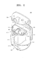
- FIG. 2 is an exploded perspective view of the cyclone dust collector of FIG. 1;
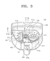
- FIG. 3 is a perspective view of a cyclone body of FIG 2;
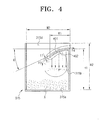
- FIG. 4 is a sectional view of a cyclone chamber cut away along a line IV-IV of FIG. 3.
- FIG 1 shows a vacuum cleaner 200 adopting a cyclone dust collector 300 according to an embodiment of the present invention.
- the vacuum cleaner 200 comprises a cleaner body 250, a suction brush 210 for drawing in dust on a surface being cleaned, an operation part 230 for operating the vacuum cleaner 200, an extension pipe 220 connecting the suction brush 210 and the operation part 230, a flexible hose 240 connecting the operation part 230 and the cleaner body 250, and the cyclone dust collector 300.
- a driving motor (not shown) for supplying a suction force is mounted in the cleaner body 250.
- the cleaner body 250 includes a driving chamber (not shown) for mounting the driving motor (not shown) and a dust chamber 251 connected to the driving chamber (not shown).
- the cyclone dust collector 300 is removably mounted to centrifugally separate dust from drawn-in air.
- the cyclone dust collector 300 comprises a cover unit 330, a door unit 350 and a cyclone body 310.
- the cover unit 330 is removably mounted at an upper part of the cyclone body 310. As the cover unit 330 is mounted to the upper part of the cyclone body 310, a dust moving path 318 is naturally formed between a cyclone chamber 313 and a dust chamber 315. Through the dust moving path 318, the dust separated from dust-laden air in the cyclone chamber 313 moves into the dust chamber 315.
- a suction path 331 is formed in the middle of the cover unit 330.
- the suction path 331 is fluidly communicated with the flexible hose 240 (FIG. 1).
- the door unit 350 is hinged to a lower part of the cyclone body 310 to open in an arrow G direction and close in an arrow G' direction with respect to a hinge 351.
- a bottom surface of a connection path 311 (FIG. 3) and the dust chamber 315 is opened, and accordingly, the dust collected in the connection path 311 (FIG. 3) and the dust chamber 315 falls to be discharged.
- a button 319a formed at a handle 319 is pressed to thereby depress a hook (not shown) connected to one side of the door unit 350. Accordingly, connection between the door unit 350 and the hook (not shown) is released, and therefore, the door unit 350 is opened as the other side thereof rotates with respect to the hinge 351.
- the user has to forcibly rotate the door unit 350 with respect to the hinge 351 in the G' direction, such that the one side of the door unit 350 is fastened with the hook (not shown).
- the cyclone body 310 comprises the handle 319, the connection path 311, the cyclone chamber 313, and the dust chamber 315.
- the handle 319 substantially has a flattened U shape, and is mounted on a front of the cyclone body 310 to be grabbed by the user when separating the cyclone body 310 from the cleaner body 250.
- the handle 319 includes the button 319a for opening the door unit 350 at a lower part thereof, and a link member (not shown) for connecting the button 319a and the hook (not shown) therein.
- connection path 311 is formed in the middle of the cyclone body 310 and fluidly communicated with the suction path 331 (FIG. 2) so as to guide the dust-laden air drawn into the suction path 331 1 (FIG 2) toward the cyclone chamber 313.
- a mesh hole 311a is formed to mount a mesh filter M capable of filtering fine dust.
- the connection path 311 is fluidly communicated with the driving motor (not shown) through the mesh filter M.
- the bottom of the connection path 311 is opened as opening the door unit 350, thereby discharging the dust collected on the bottom of the connection path 311.
- the cyclone chamber 313 is disposed on the right with respect to the connection path 311 in the cyclone body 310, referring to FIG. 2, to centrifugally separate the dust from the dust-laden air.
- an entering path 313a and a discharge path 314 are formed on a bottom surface of the cyclone chamber 313.
- the air drawn in through the suction path 331 (FIG. 2) and the connection path 311 flows into the cyclone chamber 313 through the entering path 313a, and the centrifuged air is discharged through the discharge path 314.
- the discharge path 314 for discharging the centrifuged air has a substantially circular section and a predetermined height from a mid-bottom in the cyclone chamber 313.
- the discharge path 314 may be formed integrally with or separately from the cyclone chamber 313.
- the discharge path 314 has four ribs 317 for reducing noise and loss of pressure which are generated when the air is discharged through the discharge path 314.
- the dust chamber 315 is formed on the left with respect to the connection path 311 within the cyclone body 310 to collect the dust separated at the cyclone chamber 313.
- a bottom of the dust chamber 315 is opened by opening the door unit 350, such that the dust collected on the bottom of the dust chamber 315 can be discharged.
- a backflow prevention member 400 is mounted in the dust chamber 315 to prevent the separated and collected dust X from flowing back to the cyclone chamber 313.
- the backflow prevention member 400 has a substantially arc-shaped section.
- the backflow prevention member 400 is made of the same material as the cyclone body 310, such as transparent acryl, having a length L1, a width W1 and a thickness t1.
- the length L1 and the width W1 of the backflow prevention member 400 are properly determined so as to prevent the dust collected in the dust chamber 315 from flowing back to the cyclone chamber 313.
- the length L1 of the backflow prevention member and a length L2 of the dust chamber are substantially in the ratio of 0.8:1 to 0.9:1.
- the width W1 of the backflow prevention member and a width W2 of the dust chamber are substantially in the ratio of 0.4:1 to 0.5:1.
- the backflow prevention member 400 covers approximately 30-50% of a top area 315d of the dust chamber 315.
- the backflow prevention member 400 is attached on a right wall 315b and a rear wall 315c of the dust chamber 315 by welding or by an adhesive to be inclined toward the bottom 315a of the dust chamber 315 by an angle ⁇ .
- a height H for mounting the backflow prevention member 400 and a height H2 of the dust chamber 315 are preferably in the ratio of 0.8:1 to 0.9: 1.
- the angle ⁇ is approximately 20° to 25°, such that the dust, as flowing into the dust chamber 315 in an arrowed direction F3, can overcome friction with an upper surface 401 of the backflow prevention member 400 and fall to the bottom 315a of the dust chamber 315.
- the suction force is transmitted to the suction brush 210 through the cyclone dust collector 300.
- the suction brush 210 draws in dust-laden air on a surface being cleaned.
- the drawn-in air enters the suction path 331 of the cover unit 330, passing through the suction brush 210, the extension pipe 220 and the flexible hose 240 in an arrowed direction F.
- a part of the drawn-in air is passed through the mesh filter M disposed in the mesh hole 311a, in the connection path 311, in an arrowed direction F1, and is discharged out of the cyclone dust collector 300 through a discharge filter 500 formed at a rear side of the cyclone body 310, in an arrowed direction F7.
- the rest part of the drawn-in air flows into the entering path 313a of the cyclone chamber 313 in an arrowed direction F2.
- the drawn-in air while rotating, rises from the bottom of the cyclone chamber 313 up to an upper part (not shown) of the cover unit 330. During this, the dust is bounced out to the dust chamber 315 formed on the left of the cyclone body 310 in the arrowed direction F3 by a centrifugal force.
- Dust-separated air collides with the upper part (not shown) of the cover unit 330, descends in an arrowed direction F5, and is discharged out of the discharge path 314 formed on the center of the cyclone chamber 313.
- the air discharged out of the discharge path 314 is discharged to the outside of the cyclone dust collector 300 through the discharge filter 500 formed at the rear side of the cyclone body 310, in an arrowed direction F6.
- the air which entered the connection path 311 is mostly discharged through the mesh filter M mounted in the mesh hole 311a at the beginning of driving of the vacuum cleaner.
- the mesh filter M is stuffed by dust or foreign substances, most of the air flows to the entering path 313a of the cyclone chamber 313 because fluid such as air is apt to move to a side having a relatively lower resistance.
- loss of pressure can be reduced when the vacuum cleaner is initially driven.
- the dust bounced out to the dust chamber 315 moves in the arrowed direction F3 along the dust moving path 318 and the upper surface 401 of the backflow prevention member 400 and falls on the bottom 315a of the dust chamber 315.
- the dust-separated air moves along a lower surface 402 and the upper surface 401 of the backflow prevention member 400 in an arrowed direction F4 and enters the cyclone chamber 313. At this time, the dust collected in the dust chamber 315 may flow back to the cyclone chamber 313.
- the dust since capacity of the dust chamber 315 is relatively small, the dust easily fills the dust chamber 315, piling up near the cyclone chamber 313.
- the dust in the dust chamber 315 can be prevented from flowing back to the cyclone chamber 313.
- the dust flowing back to the cyclone chamber 313 in the arrowed direction F4, is collided with the lower surface 402 of the backflow prevention member 400.
- the backflow prevention member 400 can restrain the collected dust from being flowing back to the cyclone chamber 313. As a result, deterioration of suction efficiency, caused by the dust blocking the discharge path 314 and the discharge filter 500, can be prevented.
Landscapes
- Engineering & Computer Science (AREA)
- Mechanical Engineering (AREA)
- Chemical & Material Sciences (AREA)
- Chemical Kinetics & Catalysis (AREA)
- Filters For Electric Vacuum Cleaners (AREA)
- Cyclones (AREA)
Applications Claiming Priority (1)
| Application Number | Priority Date | Filing Date | Title |
|---|---|---|---|
| KR1020040082107A KR100595916B1 (ko) | 2004-10-14 | 2004-10-14 | 사이클론 집진장치 |
Publications (2)
| Publication Number | Publication Date |
|---|---|
| EP1647218A2 true EP1647218A2 (de) | 2006-04-19 |
| EP1647218A3 EP1647218A3 (de) | 2006-05-10 |
Family
ID=35601818
Family Applications (1)
| Application Number | Title | Priority Date | Filing Date |
|---|---|---|---|
| EP05290543A Pending EP1647218A3 (de) | 2004-10-14 | 2005-03-10 | Zyklon-Staubsammelvorrichtung |
Country Status (6)
| Country | Link |
|---|---|
| US (1) | US7381236B2 (de) |
| EP (1) | EP1647218A3 (de) |
| JP (1) | JP2006110321A (de) |
| KR (1) | KR100595916B1 (de) |
| CN (1) | CN100393266C (de) |
| RU (1) | RU2294685C2 (de) |
Cited By (3)
| Publication number | Priority date | Publication date | Assignee | Title |
|---|---|---|---|---|
| WO2013093754A1 (en) * | 2011-12-19 | 2013-06-27 | Koninklijke Philips Electronics N.V. | Cyclone vacuum cleaner and cyclone separation device |
| WO2015157336A1 (en) * | 2014-04-08 | 2015-10-15 | Euro-Pro Operating Llc | Surface cleaning apparatus |
| CN105852737A (zh) * | 2016-05-27 | 2016-08-17 | 苏州川欧电器有限公司 | 一种多功能地拖 |
Families Citing this family (61)
| Publication number | Priority date | Publication date | Assignee | Title |
|---|---|---|---|---|
| US20070144116A1 (en) * | 2005-12-23 | 2007-06-28 | Samsung Electronics Co., Ltd. | Cyclonic cleaner |
| CA2542630A1 (en) * | 2006-04-10 | 2007-10-10 | Enbridge Gas Distribution Inc. | Service tee cutting apparatus and abandonment method |
| US20070294858A1 (en) * | 2006-06-23 | 2007-12-27 | Murphy Jerry A | Portable Vacuum Canister and Method of Waste Disposal Therefrom |
| US12220099B2 (en) | 2006-12-12 | 2025-02-11 | Omachron Intellectual Property Inc. | Surface cleaning apparatus |
| EP2117400A4 (de) | 2006-12-12 | 2010-06-23 | Gbd Corp | Umrüstbare oberflächenreinigungsvorrichtung |
| US8950039B2 (en) | 2009-03-11 | 2015-02-10 | G.B.D. Corp. | Configuration of a surface cleaning apparatus |
| US10765277B2 (en) | 2006-12-12 | 2020-09-08 | Omachron Intellectual Property Inc. | Configuration of a surface cleaning apparatus |
| US12048409B2 (en) | 2007-03-11 | 2024-07-30 | Omachron Intellectual Property Inc. | Portable surface cleaning apparatus |
| US11751733B2 (en) | 2007-08-29 | 2023-09-12 | Omachron Intellectual Property Inc. | Portable surface cleaning apparatus |
| US7828876B2 (en) * | 2007-04-20 | 2010-11-09 | Southern Company | Systems and methods for organic particulate filtration |
| US7691161B2 (en) * | 2008-01-31 | 2010-04-06 | Samsung Gwangju Electronics Co., Ltd. | Cyclone dust-collecting apparatus |
| US8062398B2 (en) * | 2008-12-19 | 2011-11-22 | Bissell Homecare, Inc. | Vacuum cleaner and cyclone module therefor |
| US9591952B2 (en) | 2009-03-11 | 2017-03-14 | Omachron Intellectual Property Inc. | Hand vacuum cleaner with removable dirt chamber |
| US9392916B2 (en) | 2009-03-13 | 2016-07-19 | Omachron Intellectual Property Inc. | Surface cleaning apparatus |
| US9226633B2 (en) | 2009-03-13 | 2016-01-05 | Omachron Intellectual Property Inc. | Surface cleaning apparatus |
| US9591953B2 (en) | 2009-03-13 | 2017-03-14 | Omachron Intellectual Property Inc. | Surface cleaning apparatus |
| US9427122B2 (en) | 2009-03-13 | 2016-08-30 | Omachron Intellectual Property Inc. | Surface cleaning apparatus |
| US9480373B2 (en) | 2009-03-13 | 2016-11-01 | Omachron Intellectual Property Inc. | Surface cleaning apparatus |
| CA2907064C (en) | 2009-03-13 | 2018-01-02 | Wayne Ernest Conrad | Portable surface cleaning apparatus |
| CA2674761C (en) | 2009-03-13 | 2016-10-04 | G.B.D. Corp. | Surface cleaning apparatus with different cleaning configurations |
| US11690489B2 (en) | 2009-03-13 | 2023-07-04 | Omachron Intellectual Property Inc. | Surface cleaning apparatus with an external dirt chamber |
| US11612288B2 (en) | 2009-03-13 | 2023-03-28 | Omachron Intellectual Property Inc. | Surface cleaning apparatus |
| US9211044B2 (en) | 2011-03-04 | 2015-12-15 | Omachron Intellectual Property Inc. | Compact surface cleaning apparatus |
| US9198551B2 (en) | 2013-02-28 | 2015-12-01 | Omachron Intellectual Property Inc. | Surface cleaning apparatus |
| RU2433778C1 (ru) * | 2009-06-25 | 2011-11-20 | Кабусики Кайся Тосиба | Пылесборное устройство и электрический пылесос |
| US9101252B2 (en) | 2011-03-03 | 2015-08-11 | G.B.D. Corp. | Configuration of a surface cleaning apparatus |
| US8769767B2 (en) | 2011-03-03 | 2014-07-08 | G.B.D. Corp. | Removable cyclone chamber and dirt collection assembly for a surface cleaning apparatus |
| US8763202B2 (en) | 2011-03-03 | 2014-07-01 | G.B.D. Corp. | Cyclone chamber and dirt collection assembly for a surface cleaning apparatus |
| US8739357B2 (en) | 2011-03-03 | 2014-06-03 | G.B.D. Corp | Filter construction for a surface cleaning apparatus |
| US8973214B2 (en) | 2011-03-03 | 2015-03-10 | G.B.D. Corp. | Cyclone chamber and dirt collection assembly for a surface cleaning apparatus |
| US8739359B2 (en) | 2011-03-03 | 2014-06-03 | G.B.D. Corp. | Configuration of a surface cleaning apparatus |
| US8813306B2 (en) | 2011-03-03 | 2014-08-26 | G.B.D. Corp. | Openable side compartments for a surface cleaning apparatus |
| US8646149B2 (en) | 2011-03-03 | 2014-02-11 | G.B.D. Corp. | Filter housing construction for a surface cleaning apparatus |
| US8869345B2 (en) | 2011-03-03 | 2014-10-28 | G.B.D. Corp. | Canister vacuum cleaner |
| US8978198B2 (en) | 2011-03-03 | 2015-03-17 | G.B.D. Corp. | Filter housing for a surface cleaning apparatus |
| US8973212B2 (en) | 2011-03-03 | 2015-03-10 | G.B.D. Corp. | Filter housing construction for a surface cleaning apparatus |
| US8997309B2 (en) | 2012-03-02 | 2015-04-07 | G.B.D. Corp. | Surface cleaning apparatus |
| US9009912B2 (en) | 2011-03-04 | 2015-04-21 | G.B.D. Corp. | Dirt separation apparatus for a surface cleaning apparatus |
| US8863352B2 (en) | 2011-03-04 | 2014-10-21 | G.B.D. Corp. | Dirt collection chamber for a surface cleaning apparatus |
| WO2012119220A1 (en) * | 2011-03-04 | 2012-09-13 | Gbd Corp. | Surface cleaning apparatus |
| US9204772B2 (en) | 2011-03-04 | 2015-12-08 | Omachron Intellectual Property Inc. | Dirt collection chamber for a surface cleaning apparatus |
| US8800104B2 (en) | 2011-03-04 | 2014-08-12 | G.B.D. Corp. | Dirt collection chamber with a recessed column |
| DE102012202286A1 (de) * | 2012-02-15 | 2013-08-22 | BSH Bosch und Siemens Hausgeräte GmbH | Auffangbehälter zum Auffangen von Partikeln für einen Wirbelabscheider |
| US9215960B2 (en) | 2013-02-28 | 2015-12-22 | Omachron Intellectual Property Inc. | Surface cleaning apparatus |
| US9456721B2 (en) | 2013-02-28 | 2016-10-04 | Omachron Intellectual Property Inc. | Surface cleaning apparatus |
| US9314138B2 (en) | 2013-02-28 | 2016-04-19 | Omachron Intellectual Property Inc. | Surface cleaning apparatus |
| US9364127B2 (en) | 2013-02-28 | 2016-06-14 | Omachron Intellectual Property Inc. | Surface cleaning apparatus |
| GB2522658B (en) * | 2014-01-31 | 2016-04-06 | Dyson Technology Ltd | Separating apparatus in a vacuum cleaner |
| WO2015123538A1 (en) | 2014-02-14 | 2015-08-20 | Techtronic Industries Co. Ltd. | Vacuum cleaner with a separator received within the dirt collection chamber |
| WO2016065146A1 (en) | 2014-10-22 | 2016-04-28 | Techtronic Industries Co. Ltd. | Vacuum cleaner having cyclonic separator |
| WO2016065151A1 (en) | 2014-10-22 | 2016-04-28 | Techtronic Industries Co. Ltd. | Handheld vacuum cleaner |
| CN110123203A (zh) | 2014-10-22 | 2019-08-16 | 创科实业有限公司 | 具有旋风分离器的真空吸尘器 |
| KR102277144B1 (ko) | 2014-12-18 | 2021-07-14 | 삼성전자주식회사 | 청소기 |
| KR101653481B1 (ko) * | 2015-01-16 | 2016-09-01 | 엘지전자 주식회사 | 진공 청소기 및 집진장치 |
| US11285495B2 (en) | 2016-12-27 | 2022-03-29 | Omachron Intellectual Property Inc. | Multistage cyclone and surface cleaning apparatus having same |
| TWI666047B (zh) * | 2018-03-09 | 2019-07-21 | 緯穎科技服務股份有限公司 | 集塵器及自動除塵的電子系統 |
| JP7074576B2 (ja) * | 2018-06-14 | 2022-05-24 | 東芝ライフスタイル株式会社 | 集塵装置および電気掃除機 |
| US12514418B2 (en) | 2018-07-19 | 2026-01-06 | Omachron Intellectual Property Inc. | Hand vacuum cleaner |
| EP3698697A1 (de) * | 2019-02-25 | 2020-08-26 | Koninklijke Philips N.V. | Zyklonabscheidervorrichtung |
| DE102019121373B4 (de) * | 2019-08-07 | 2022-03-10 | Netzsch Trockenmahltechnik Gmbh | Abscheider mit partieller filtrierung |
| JP1771572S (ja) * | 2023-10-18 | 2024-05-28 | 切削工具 |
Family Cites Families (14)
| Publication number | Priority date | Publication date | Assignee | Title |
|---|---|---|---|---|
| SU1260003A1 (ru) * | 1985-03-13 | 1986-09-30 | Всесоюзный Проектно-Технологический Институт По Электробытовым Машинам И Приборам | Пылесос дл уборки электризующейс пыли и порошка |
| SU1764625A1 (ru) * | 1990-09-27 | 1992-09-30 | В.А.Д тлов и Б.В.Иванов | Пылесос дл уборки пыли и порошка |
| JP3350025B2 (ja) | 1991-03-18 | 2002-11-25 | 松下電器産業株式会社 | 電気掃除機 |
| DE9303083U1 (de) | 1993-03-03 | 1993-04-15 | Electrostar Schöttle GmbH & Co, 7313 Reichenbach | Staubsauger, insbesondere Zyklonstaubsauger mit Filter |
| KR100437364B1 (ko) | 2000-07-26 | 2004-06-25 | 삼성광주전자 주식회사 | 진공청소기의 사이클론 집진장치 |
| KR100437371B1 (ko) * | 2000-07-26 | 2004-06-25 | 삼성광주전자 주식회사 | 진공청소기의 사이클론 집진장치 |
| KR100444553B1 (ko) * | 2001-09-17 | 2004-08-16 | 삼성광주전자 주식회사 | 진공청소기의 사이클론 집진장치 |
| KR100444322B1 (ko) | 2001-12-12 | 2004-08-16 | 삼성광주전자 주식회사 | 진공청소기의 사이클론 집진장치 |
| JP2003180569A (ja) | 2001-12-21 | 2003-07-02 | Sanyo Electric Co Ltd | 電気掃除機 |
| JP2003190058A (ja) | 2001-12-27 | 2003-07-08 | Matsushita Electric Ind Co Ltd | 電気掃除機 |
| DE10248087B4 (de) | 2002-10-15 | 2011-05-19 | BSH Bosch und Siemens Hausgeräte GmbH | Staubsauger mit einem entnehmbaren Staubsammelbehälter |
| DE20306405U1 (de) | 2003-04-24 | 2003-08-28 | BSH Bosch und Siemens Hausgeräte GmbH, 81669 München | Entnehmbarer Staubsammelbehälter |
| KR100474078B1 (ko) * | 2003-06-02 | 2005-03-14 | 삼성광주전자 주식회사 | 진공청소기의 사이클론 집진장치 |
| JP2006055622A (ja) | 2004-08-23 | 2006-03-02 | Samsung Kwangju Electronics Co Ltd | サイクロン集塵装置及びこれを備えた掃除機 |
-
2004
- 2004-10-14 KR KR1020040082107A patent/KR100595916B1/ko not_active Expired - Fee Related
-
2005
- 2005-02-24 JP JP2005048324A patent/JP2006110321A/ja active Pending
- 2005-03-04 US US11/072,386 patent/US7381236B2/en not_active Expired - Fee Related
- 2005-03-10 EP EP05290543A patent/EP1647218A3/de active Pending
- 2005-03-16 CN CNB2005100547989A patent/CN100393266C/zh not_active Expired - Fee Related
- 2005-03-25 RU RU2005109377/12A patent/RU2294685C2/ru not_active IP Right Cessation
Cited By (8)
| Publication number | Priority date | Publication date | Assignee | Title |
|---|---|---|---|---|
| WO2013093754A1 (en) * | 2011-12-19 | 2013-06-27 | Koninklijke Philips Electronics N.V. | Cyclone vacuum cleaner and cyclone separation device |
| RU2620710C2 (ru) * | 2011-12-19 | 2017-05-29 | Конинклейке Филипс Н.В. | Циклонный пылесос и устройство циклонного сепаратора |
| US9820622B2 (en) | 2011-12-19 | 2017-11-21 | Koninklijke Philips N.V. | Cyclone vacuum cleaner and cyclone separation device |
| WO2015157336A1 (en) * | 2014-04-08 | 2015-10-15 | Euro-Pro Operating Llc | Surface cleaning apparatus |
| CN106163358A (zh) * | 2014-04-08 | 2016-11-23 | 尚科宁家运营有限公司 | 表面清洁装置 |
| CN106163358B (zh) * | 2014-04-08 | 2019-07-26 | 尚科宁家运营有限公司 | 表面清洁装置 |
| CN105852737A (zh) * | 2016-05-27 | 2016-08-17 | 苏州川欧电器有限公司 | 一种多功能地拖 |
| CN105852737B (zh) * | 2016-05-27 | 2018-03-02 | 苏州川欧电器有限公司 | 一种多功能地拖 |
Also Published As
| Publication number | Publication date |
|---|---|
| EP1647218A3 (de) | 2006-05-10 |
| KR100595916B1 (ko) | 2006-07-05 |
| KR20060033147A (ko) | 2006-04-19 |
| US20060080947A1 (en) | 2006-04-20 |
| RU2005109377A (ru) | 2006-09-10 |
| JP2006110321A (ja) | 2006-04-27 |
| CN100393266C (zh) | 2008-06-11 |
| CN1759796A (zh) | 2006-04-19 |
| US7381236B2 (en) | 2008-06-03 |
| RU2294685C2 (ru) | 2007-03-10 |
Similar Documents
| Publication | Publication Date | Title |
|---|---|---|
| US7381236B2 (en) | Cyclone dust-separating apparatus | |
| US7501002B2 (en) | Cyclone dust separator and a vacuum cleaner having the same | |
| KR100554238B1 (ko) | 사이클론 집진장치 | |
| US7601188B2 (en) | Vacuum cleaner | |
| US7857878B2 (en) | Dust collection unit for vacuum cleaner | |
| US7381234B2 (en) | Dust collecting apparatus for vacuum cleaner | |
| US7410535B2 (en) | Cyclone separating apparatus and a vacuum cleaner having the same | |
| EP1688184A1 (de) | Zyklonstaubsammelvorrichtung mit einem flexiblen Luftrückströmungsdeflektor | |
| US20060272299A1 (en) | Cyclone dust collecting apparatus | |
| GB2456192A (en) | Sloped upper wall of cyclone inflow channel | |
| KR20160089201A (ko) | 진공 청소기용 집진장치 | |
| KR100540793B1 (ko) | 사이클론 집진장치 및 이를 구비한 진공청소기 | |
| EP1692991B1 (de) | Staubsammler für Staubsauger | |
| EP1692992B1 (de) | Staubsammler für Staubsauger | |
| EP1692993A1 (de) | Staubsammler für Staubsauger | |
| KR100548933B1 (ko) | 진공 청소기의 흡입구조 | |
| KR100672474B1 (ko) | 진공청소기 | |
| KR100651280B1 (ko) | 진공 청소기의 커버구조 | |
| KR100577277B1 (ko) | 진공청소기 | |
| KR100553044B1 (ko) | 진공 청소기의 집진유닛 | |
| GB2425078A (en) | Cyclonic separator with noise reducing feature | |
| KR20060074616A (ko) | 진공 청소기의 유로구조 |
Legal Events
| Date | Code | Title | Description |
|---|---|---|---|
| PUAI | Public reference made under article 153(3) epc to a published international application that has entered the european phase |
Free format text: ORIGINAL CODE: 0009012 |
|
| PUAL | Search report despatched |
Free format text: ORIGINAL CODE: 0009013 |
|
| AK | Designated contracting states |
Kind code of ref document: A2 Designated state(s): AT BE BG CH CY CZ DE DK EE ES FI FR GB GR HU IE IS IT LI LT LU MC NL PL PT RO SE SI SK TR |
|
| AX | Request for extension of the european patent |
Extension state: AL BA HR LV MK YU |
|
| AK | Designated contracting states |
Kind code of ref document: A3 Designated state(s): AT BE BG CH CY CZ DE DK EE ES FI FR GB GR HU IE IS IT LI LT LU MC NL PL PT RO SE SI SK TR |
|
| AX | Request for extension of the european patent |
Extension state: AL BA HR LV MK YU |
|
| RIC1 | Information provided on ipc code assigned before grant |
Ipc: B04C 5/185 20060101ALI20060317BHEP Ipc: A47L 5/36 20060101ALI20060317BHEP Ipc: A47L 9/16 20060101AFI20060125BHEP |
|
| 17P | Request for examination filed |
Effective date: 20060817 |
|
| AKX | Designation fees paid |
Designated state(s): DE ES FR GB IT NL |
|
| 17Q | First examination report despatched |
Effective date: 20070315 |
|
| GRAP | Despatch of communication of intention to grant a patent |
Free format text: ORIGINAL CODE: EPIDOSNIGR1 |
|
| STAA | Information on the status of an ep patent application or granted ep patent |
Free format text: STATUS: GRANT OF PATENT IS INTENDED |
|
| R17C | First examination report despatched (corrected) |
Effective date: 20070315 |