EP1646296B1 - Stollen mit selbstschneidendem gewinde für gummiträger von schuhen, reifen und ähnlichen - Google Patents
Stollen mit selbstschneidendem gewinde für gummiträger von schuhen, reifen und ähnlichen Download PDFInfo
- Publication number
- EP1646296B1 EP1646296B1 EP04740837A EP04740837A EP1646296B1 EP 1646296 B1 EP1646296 B1 EP 1646296B1 EP 04740837 A EP04740837 A EP 04740837A EP 04740837 A EP04740837 A EP 04740837A EP 1646296 B1 EP1646296 B1 EP 1646296B1
- Authority
- EP
- European Patent Office
- Prior art keywords
- stud
- self
- support
- core
- tool
- Prior art date
- Legal status (The legal status is an assumption and is not a legal conclusion. Google has not performed a legal analysis and makes no representation as to the accuracy of the status listed.)
- Expired - Lifetime
Links
- 238000010079 rubber tapping Methods 0.000 title claims abstract description 19
- 238000003780 insertion Methods 0.000 description 4
- 230000037431 insertion Effects 0.000 description 4
- 230000014759 maintenance of location Effects 0.000 description 3
- 239000000463 material Substances 0.000 description 2
- 238000012986 modification Methods 0.000 description 1
- 230000004048 modification Effects 0.000 description 1
- 230000035515 penetration Effects 0.000 description 1
- 230000000717 retained effect Effects 0.000 description 1
- 239000002023 wood Substances 0.000 description 1
Images

Classifications
-
- A—HUMAN NECESSITIES
- A43—FOOTWEAR
- A43C—FASTENINGS OR ATTACHMENTS OF FOOTWEAR; LACES IN GENERAL
- A43C15/00—Non-skid devices or attachments
- A43C15/16—Studs or cleats for football or like boots
- A43C15/161—Studs or cleats for football or like boots characterised by the attachment to the sole
-
- A—HUMAN NECESSITIES
- A43—FOOTWEAR
- A43B—CHARACTERISTIC FEATURES OF FOOTWEAR; PARTS OF FOOTWEAR
- A43B1/00—Footwear characterised by the material
- A43B1/0054—Footwear characterised by the material provided with magnets, magnetic parts or magnetic substances
-
- B—PERFORMING OPERATIONS; TRANSPORTING
- B60—VEHICLES IN GENERAL
- B60C—VEHICLE TYRES; TYRE INFLATION; TYRE CHANGING; CONNECTING VALVES TO INFLATABLE ELASTIC BODIES IN GENERAL; DEVICES OR ARRANGEMENTS RELATED TO TYRES
- B60C11/00—Tyre tread bands; Tread patterns; Anti-skid inserts
- B60C11/14—Anti-skid inserts, e.g. vulcanised into the tread band
- B60C11/16—Anti-skid inserts, e.g. vulcanised into the tread band of plug form, e.g. made from metal, textile
- B60C11/1637—Attachment of the plugs into the tread, e.g. screwed
Definitions
- the present invention relates to a self-tapping stud for rubber supports of shoes, tyres and the like.
- Studs of this type currently exist comprising a body provided with a threaded portion to be connected to a rubber support (for example a shoe sole or a tyre) and, at its opposite end, a head of particularly hard material to ensure that the shoe or tyre grips the ground or to protect the sole against wear.
- a rubber support for example a shoe sole or a tyre
- a head of particularly hard material to ensure that the shoe or tyre grips the ground or to protect the sole against wear.
- the threaded portion of said studs presents a cylindrical core from which a thread projects with its free helical edge contained substantially within a conical surface converging towards the free end of the thread (to facilitate its insertion into the rubber).
- the thread and core are similar to those of self-tapping wood screws.
- the free end of the thread (that which enters first into the rubber support when the stud is applied) presents in some cases a small cutting edge positioned substantially in a direction perpendicular to a core axis.
- This stud is applied to rubber supports by a tool comprising two mutually communicating seats, the more inner seat receiving the head of the stud and the more outer its body; for its insertion, the stud is mounted on the tool with the threaded portion projecting, and is screwed into the support such that during its screwing, the stud leaves the seats naturally and remains locked in the support.
- the depth of the tool seat and the height of the stud head have to be calculated to achieve optimum positioning of the body within the rubber support.
- the stud should self-release naturally.
- the stud often does not automatically leave the seats in which it is housed but, because of rotation, the threaded part tears the rubber from the support, leaving the support surface damaged and the stud badly positioned.
- the technical aim of the present invention is therefore to provide a self-tapping stud for rubber supports of shoes, tyres and the like, by which the stated technical drawbacks of the known art are overcome.
- an object of the invention is to provide a stud which grips the rubber support in an optimum manner even if the threaded portions are of small dimensions (in the longitudinal direction, i.e. along the axis of the stud core).
- the stud of the invention does not escape, does not bend, and can project from the rubber support to a sufficiently large extent, depending on requirements.
- Another object of the invention is to provide a stud which can be applied to the rubber support without causing problems to the support structure or damage to its surface.
- a further object of the invention is to provide a mounting tool for said stud which enables the stud to be applied in an extremely reliable manner, with a very low risk of tearing rubber portions of the support.
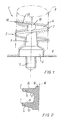
- the stud 1 comprises a body 2 presenting a threaded portion 3 lockable into the rubber support 4 (the stud 1 is shown locked into the support 4 in Figure 1 ) and a head 5 which projects from the support 4 when the stud is mounted.
- the threaded portion 3 presents a thread 6 provided with a free helical edge 7 which extends along a substantially cylindrical surface 8.
- the threaded portion 3 also presents a substantially conical or frusto-conical core 9, with its converging end 10 disposed towards the free end of the core 9.
- the thread 6 of the threaded portion 3 is provided at its free start 12 with a cutting edge 13, which is orientated with the same inclination as the thread and could reach the centre of the core.
- the thread 6 presents a good capacity for penetration and retention within the support 4 along its entire length.
- a first thread profile 15 facing the convergent end 10 of the core 9 is substantially perpendicular to an axis 16 of the core 9, while a second thread profile 17 facing the body 2 of the core 9 is substantially inclined to the axis 16 of the core 9; preferably the second profile 17 is inclined at an obtuse angle of between 95 and 110 degrees to the axis of said core, depending on the rubber mix.
- the free helical edge 7 presents a substantially flat longitudinal profile having dimensions between 0.4 and 1.6 millimetres based on the stud dimensions.
- the angle between the second profile 17 and the core axis is approximately 95° and the longitudinal profile of the free helical edge 7 presents a length of approximately 1.6 millimetres.
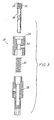
- a mounting tool for studs of the stated type is indicated overall by the reference numeral 20.
- the tool 20 comprises a seat 21 to receive as an exact fit the head 5 of the stud 1 and/or the body 2 if this is faceted (in the form of an ellipse 3A or having a notch 4A at its end) and an abutment surface 22 adjacent to the mouth 23 of the seat 21, so that the tool 20 enables the stud 1 to be screwed into the support 4 such that the abutment surface 4 abuts against the support 4, an indication that the stud is completely mounted being given when the surface of the first element 24 abuts against the surface of the second element 25.
- the tool 20 also comprises a body 24, 25 in which an operating element 26 is slidable, carrying at its end the seat 21.
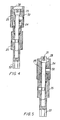
- the body presents a first element 24 and a second element 25 which are slidable one in the other against and by the action of elastic means 27 such that the body can assume a first extended position (in which as shown in Figure 4 the element 24 and the element 25 are spaced apart from each other longitudinally), in which the first element 24 defines a widened chamber 28 facing the seat 21 of the operating element 26, to receive as an exact fit at least a part of the body 2 of the stud 1, and a second contracted position (in which as shown in Figure 5 the element 24 and element 25 are inserted longitudinal one into the other until they mutually abut), in which the seat 21 of the operating element 26 projects from the first element 24.
- the seat also preferably comprises magnetic means 29 such as a magnet to retain the stud 1 in the seat during mounting and removal.
- the tool of the first embodiment enables studs to be both applied and extracted; specifically, in the configuration shown in Figure 4 the tool is particularly suitable for applying studs, whereas in that of Figure 5 it is particularly suitable for extracting them.
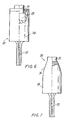
- the tool 20 comprises a body 24 from which the seat 21 projects.
- Magnetic means in the form of a magnet 29 are again provided in this case.
- This embodiment of the tool 20 is suitable both for mounting studs 1 and for extracting them.
- the tool 20 comprises the body 24 from which the seat 21 projects, the body 24 presenting close to said seat an end portion 31 which converges to facilitate visibility in the seat region.
- This embodiment of the tool is particularly suitable for removing studs 1, as it provides high visibility in the seat region; the tool can evidently also be used for mounting.
- the tool 20 presents a faceted shank 32 for its connection to an electric screwdriver or drill, enabling the studs to be applied easily and quickly; in other examples the tool can be used with a manual handgrip.
- the stud has its body 2 elliptically faceted at 3A and notched at 2a, with the head 5 presenting rounded or round profiles.
- the mounting and/or removal tool 20 presents a very wide seat 21 for receiving the faceted portions of the body. Adjacent to the seat 21 this tool carries the retention magnet 29.
- mounting is achieved by setting the tool in the configuration shown in Figure 4 , enabling it to correctly receive the stud 1.
- the stud 1 is then inserted by inserting its head 5 into the seat 21 and its body 2 at least partially into the wide chamber 28 (the body 2 is preferably completely housed in the wide chamber 28).
- Insertion is very simple because the cutting edge 13 has the same inclination as the thread and the thread presents large longitudinal dimensions (pitch), the connection obtained being very secure because of the large surface of the thread 6 which is obtained by making the free edge of the thread 6 with an obtuse angle along the cylindrical surface 8 and by making the core 9 cylindrical to increase the dimensions of the thread for gripping along the free portion of the stud 1.
- the stud is extracted with the tool of Figures 3-5 by firstly setting the tool in the configuration of Figure 5 ; the head of the stud 1 (which projects from the support) is then inserted into the seat 21 and the tool rotated to unscrew the stud.
- the magnet 29 enables the stud to be retained within the seat 21, 28 until it has been brought into contact with and properly positioned on the support.
- the second embodiment of the tool is used by inserting the head 5 of the stud 1 into the seat 21 of the tool 20 and then rotating the tool 20 while pressing it against the surface of the support to screw in the stud 1 (the stud is mounted when the surface 22 abuts against the support 4).
- This tool can also be used for unscrewing, although for this function the third embodiment of the tool 20 is particularly suitable.
- the third embodiment of the tool is particularly suitable for unscrewing because it provides excellent visibility around the seat 21, enabling the head 5 of the stud 1 projecting from the support to be easily and quickly inserted therein; it can also be used for screwing and hence for mounting studs in the rubber support.
- the self-tapping stud for rubber supports of shoes, tyres and the like of the invention and the tool for mounting said stud are particularly advantageous because studs can be very securely fixed into a rubber support without damaging the support.
Landscapes
- Engineering & Computer Science (AREA)
- Mechanical Engineering (AREA)
- Footwear And Its Accessory, Manufacturing Method And Apparatuses (AREA)
- Tires In General (AREA)
Claims (8)
- Selbstschneidender Spike (1) für Gummiträger (4) von Schuhen, Reifen und dergleichen mit einem Körper (2), der einen mit einem Gewinde versehenen Abschnitt (3) aufweist, der in dem Gummiträger befestigt werden kann, und einem Kopf (5), der von dem Träger vorsteht, wenn der Spike befestigt worden ist, dadurch gekennzeichnet, dass der mit einem Gewinde versehene Abschnitt ein Gewinde (6), das mit einer freien wendelförmigen Kante (7) versehen ist, die entlang einer zylindrischen Fläche (8) verläuft, und einen konischen oder kegelstumpfförmigen Kern (9) aufweist und dass er an seinem freien Beginn mit einer Schneidkante (13) versehen ist, die mit derselben Neigung wie das Gewinde ausgerichtet ist und das Zentrum des Kerns (9) erreichen könnte.
- Selbstschneidender Spike nach dem vorhergehenden Anspruch, dadurch gekennzeichnet, dass ein erstes Gewindeprofil (15), das dem zusammenlaufenden Ende (10) des Kerns (9) zugewandt ist, im wesentlichen senkrecht zu einer Achse (16) des Kerns (9) ist.
- Selbstschneidender Spike nach einem oder mehreren der vorhergehenden Ansprüche, dadurch gekennzeichnet, dass ein zweites Gewindeprofil (17), das dem Körper des Kerns (9) zugewandt ist, im wesentlichen zu einer Achse (16) des Kerns (9) geneigt ist.
- Selbstschneidender Spike nach einem oder mehreren der vorhergehenden Ansprüche, dadurch gekennzeichnet, dass das zweite Profil (17) in einem stumpfen Winkel zu einer Achse (16) des Kerns (9) geneigt ist.
- Selbstschneidender Spike nach einem oder mehreren der vorhergehenden Ansprüche, dadurch gekennzeichnet, dass der stumpfe Winkel zwischen 95 und 110 Grad beträgt.
- Selbstschneidender Spike nach einem oder mehreren der vorhergehenden Ansprüche, dadurch gekennzeichnet, dass die freie wendelförmige Kante (7) ein im wesentlichen ebenes Längsprofil aufweist.
- Selbstschneidender Spike nach einem oder mehreren der vorhergehenden Ansprüche, dadurch gekennzeichnet, dass das im wesentlichen ebene Längsprofil Abmessungen zwischen 0,4 und 1,6 mm aufweist.
- Selbstschneidender Spike nach einem oder mehreren der vorhergehenden Ansprüche, dadurch gekennzeichnet, dass der Körper (2) facettiert (2a) ist, wobei der Teil (5) ein abgerundetes oder rundes Profil aufweist.
Applications Claiming Priority (2)
| Application Number | Priority Date | Filing Date | Title |
|---|---|---|---|
| IT001516A ITMI20031516A1 (it) | 2003-07-23 | 2003-07-23 | Chiodo autofilettante per supporti gommosi di scarpe, pneumatici e simili ed utensile di montaggio del suddetto chiodo |
| PCT/EP2004/007551 WO2005013749A1 (en) | 2003-07-23 | 2004-07-09 | Self-tapping stud for rubber supports of shoes, tyres and the like, and a tool for mounting said stud |
Publications (2)
| Publication Number | Publication Date |
|---|---|
| EP1646296A1 EP1646296A1 (de) | 2006-04-19 |
| EP1646296B1 true EP1646296B1 (de) | 2008-07-09 |
Family
ID=34131199
Family Applications (1)
| Application Number | Title | Priority Date | Filing Date |
|---|---|---|---|
| EP04740837A Expired - Lifetime EP1646296B1 (de) | 2003-07-23 | 2004-07-09 | Stollen mit selbstschneidendem gewinde für gummiträger von schuhen, reifen und ähnlichen |
Country Status (7)
| Country | Link |
|---|---|
| US (1) | US7552550B2 (de) |
| EP (1) | EP1646296B1 (de) |
| AT (1) | ATE400202T1 (de) |
| CA (1) | CA2533093C (de) |
| DE (1) | DE602004014932D1 (de) |
| IT (1) | ITMI20031516A1 (de) |
| WO (1) | WO2005013749A1 (de) |
Families Citing this family (4)
| Publication number | Priority date | Publication date | Assignee | Title |
|---|---|---|---|---|
| US10076160B2 (en) | 2013-06-05 | 2018-09-18 | Boa Technology Inc. | Integrated closure device components and methods |
| US11618073B2 (en) | 2018-03-01 | 2023-04-04 | Pride Manufacturing Company, Llc | Method for manufacturing a traction element using a coring process |
| CA3200480A1 (en) * | 2022-05-29 | 2023-11-29 | Nine Point Eight Inc. | Bicycle pedal with elastometric surface |
| USD1074158S1 (en) * | 2023-05-09 | 2025-05-13 | Bestgrip S.R.L. | Nail |
Family Cites Families (7)
| Publication number | Priority date | Publication date | Assignee | Title |
|---|---|---|---|---|
| US3124191A (en) * | 1964-03-10 | Skidding guard for pneumatic | ||
| GB191112231A (en) | 1911-05-20 | 1912-03-28 | William Edward Carmont | Improved Construction of Non-skid Stud for India Rubber Tyres or Tyre Covers. |
| DE3148059A1 (de) | 1981-12-04 | 1983-06-16 | Sportartikelfabrik Karl Uhl, 7460 Balingen | "sohle fuer sportschuhe" |
| AU572097B2 (en) * | 1982-02-17 | 1988-05-05 | Trisport Limited | Studded footwear |
| US5458174A (en) * | 1994-06-14 | 1995-10-17 | Bruno Wessel, Inc. | Threadedly engageable tire stud |
| US5782017A (en) | 1996-11-18 | 1998-07-21 | Maven Golf Products Llc | Coupling device for a tread insert |
| US5897177A (en) * | 1997-09-09 | 1999-04-27 | Bergstrom; Scott T. | Stud having a multifaceted surface for use on a tread element |
-
2003
- 2003-07-23 IT IT001516A patent/ITMI20031516A1/it unknown
-
2004
- 2004-07-09 CA CA2533093A patent/CA2533093C/en not_active Expired - Lifetime
- 2004-07-09 AT AT04740837T patent/ATE400202T1/de not_active IP Right Cessation
- 2004-07-09 DE DE602004014932T patent/DE602004014932D1/de not_active Expired - Lifetime
- 2004-07-09 WO PCT/EP2004/007551 patent/WO2005013749A1/en not_active Ceased
- 2004-07-09 EP EP04740837A patent/EP1646296B1/de not_active Expired - Lifetime
- 2004-07-09 US US10/565,441 patent/US7552550B2/en not_active Expired - Lifetime
Also Published As
| Publication number | Publication date |
|---|---|
| EP1646296A1 (de) | 2006-04-19 |
| DE602004014932D1 (de) | 2008-08-21 |
| WO2005013749A1 (en) | 2005-02-17 |
| US20060263168A1 (en) | 2006-11-23 |
| CA2533093C (en) | 2011-12-06 |
| ITMI20031516A1 (it) | 2005-01-24 |
| ATE400202T1 (de) | 2008-07-15 |
| CA2533093A1 (en) | 2005-02-17 |
| US7552550B2 (en) | 2009-06-30 |
Similar Documents
| Publication | Publication Date | Title |
|---|---|---|
| EP0933536B1 (de) | Anker mit Gewinde | |
| CA2736503C (en) | Adjustable one way screw remover | |
| US6599063B1 (en) | Hole saw having efficient slug removal | |
| KR20170088949A (ko) | 회전 가능한 나사못 | |
| US9689416B2 (en) | Torque limiting set screw | |
| MXPA02009606A (es) | Dispositivo anti-salto de apretamiento y extraccion de sujetadores. | |
| US20250369476A1 (en) | Slot geometry | |
| US7552550B2 (en) | Self-tapping stud for rubber supports of shoes, tyres and the like | |
| US4434687A (en) | Damaged screw remover | |
| US20140150613A1 (en) | Torx Head Bit | |
| US4572035A (en) | Tool constructions for removing frozen nuts | |
| US4898398A (en) | High performance grinding king pin and associated apparatus | |
| US4706394A (en) | Golf spike holder | |
| US4603605A (en) | Thread vise | |
| US6161456A (en) | Shielded spike tool | |
| US3074187A (en) | Heel lift | |
| US4827998A (en) | Tire repair plug | |
| CN209903071U (zh) | 一种新型防滑强力套筒 | |
| US20160151897A1 (en) | Tire Stud Removal Tool with Different Fulcrum Points for Use on Tires of Varying Tread Wear | |
| KR100801845B1 (ko) | 직결나사 구조 | |
| US20130327188A1 (en) | Slip-resistant screwdriver for slotted screws and method for driving slotted screws | |
| JP3722481B2 (ja) | ネジの抜き取り工具 | |
| KR200478117Y1 (ko) | 목재에 체결이 용이한 나사못 | |
| US20240175460A1 (en) | Removable studs, tool for inserting and removing same and kit comprising studs and tool | |
| CN110509215B (zh) | 一种改进型螺丝工具套件 |
Legal Events
| Date | Code | Title | Description |
|---|---|---|---|
| PUAI | Public reference made under article 153(3) epc to a published international application that has entered the european phase |
Free format text: ORIGINAL CODE: 0009012 |
|
| 17P | Request for examination filed |
Effective date: 20060203 |
|
| AK | Designated contracting states |
Kind code of ref document: A1 Designated state(s): AT BE BG CH CY CZ DE DK EE ES FI FR GB GR HU IE IT LI LU MC NL PL PT RO SE SI SK TR |
|
| RTI1 | Title (correction) |
Free format text: SELF-TAPPING STUD FOR RUBBER SUPPORTS OF SHOES, TYRES AND THE LIKE |
|
| DAX | Request for extension of the european patent (deleted) | ||
| GRAP | Despatch of communication of intention to grant a patent |
Free format text: ORIGINAL CODE: EPIDOSNIGR1 |
|
| GRAS | Grant fee paid |
Free format text: ORIGINAL CODE: EPIDOSNIGR3 |
|
| GRAA | (expected) grant |
Free format text: ORIGINAL CODE: 0009210 |
|
| RIN1 | Information on inventor provided before grant (corrected) |
Inventor name: MAFFEIS, LUCA Inventor name: MAFFEIS, REMO |
|
| AK | Designated contracting states |
Kind code of ref document: B1 Designated state(s): AT BE BG CH CY CZ DE DK EE ES FI FR GB GR HU IE IT LI LU MC NL PL PT RO SE SI SK TR |
|
| REG | Reference to a national code |
Ref country code: GB Ref legal event code: FG4D |
|
| REG | Reference to a national code |
Ref country code: CH Ref legal event code: EP |
|
| REF | Corresponds to: |
Ref document number: 602004014932 Country of ref document: DE Date of ref document: 20080821 Kind code of ref document: P |
|
| REG | Reference to a national code |
Ref country code: IE Ref legal event code: FG4D |
|
| REG | Reference to a national code |
Ref country code: CH Ref legal event code: NV Representative=s name: R. A. EGLI & CO. PATENTANWAELTE |
|
| REG | Reference to a national code |
Ref country code: SE Ref legal event code: TRGR |
|
| NLV1 | Nl: lapsed or annulled due to failure to fulfill the requirements of art. 29p and 29m of the patents act | ||
| PG25 | Lapsed in a contracting state [announced via postgrant information from national office to epo] |
Ref country code: NL Free format text: LAPSE BECAUSE OF FAILURE TO SUBMIT A TRANSLATION OF THE DESCRIPTION OR TO PAY THE FEE WITHIN THE PRESCRIBED TIME-LIMIT Effective date: 20080709 Ref country code: PT Free format text: LAPSE BECAUSE OF FAILURE TO SUBMIT A TRANSLATION OF THE DESCRIPTION OR TO PAY THE FEE WITHIN THE PRESCRIBED TIME-LIMIT Effective date: 20081209 Ref country code: ES Free format text: LAPSE BECAUSE OF FAILURE TO SUBMIT A TRANSLATION OF THE DESCRIPTION OR TO PAY THE FEE WITHIN THE PRESCRIBED TIME-LIMIT Effective date: 20081020 |
|
| PG25 | Lapsed in a contracting state [announced via postgrant information from national office to epo] |
Ref country code: SI Free format text: LAPSE BECAUSE OF FAILURE TO SUBMIT A TRANSLATION OF THE DESCRIPTION OR TO PAY THE FEE WITHIN THE PRESCRIBED TIME-LIMIT Effective date: 20080709 Ref country code: AT Free format text: LAPSE BECAUSE OF FAILURE TO SUBMIT A TRANSLATION OF THE DESCRIPTION OR TO PAY THE FEE WITHIN THE PRESCRIBED TIME-LIMIT Effective date: 20080709 Ref country code: BG Free format text: LAPSE BECAUSE OF FAILURE TO SUBMIT A TRANSLATION OF THE DESCRIPTION OR TO PAY THE FEE WITHIN THE PRESCRIBED TIME-LIMIT Effective date: 20081009 |
|
| PG25 | Lapsed in a contracting state [announced via postgrant information from national office to epo] |
Ref country code: BE Free format text: LAPSE BECAUSE OF FAILURE TO SUBMIT A TRANSLATION OF THE DESCRIPTION OR TO PAY THE FEE WITHIN THE PRESCRIBED TIME-LIMIT Effective date: 20080709 Ref country code: MC Free format text: LAPSE BECAUSE OF NON-PAYMENT OF DUE FEES Effective date: 20080731 |
|
| REG | Reference to a national code |
Ref country code: IE Ref legal event code: MM4A |
|
| PG25 | Lapsed in a contracting state [announced via postgrant information from national office to epo] |
Ref country code: DK Free format text: LAPSE BECAUSE OF FAILURE TO SUBMIT A TRANSLATION OF THE DESCRIPTION OR TO PAY THE FEE WITHIN THE PRESCRIBED TIME-LIMIT Effective date: 20080709 Ref country code: EE Free format text: LAPSE BECAUSE OF FAILURE TO SUBMIT A TRANSLATION OF THE DESCRIPTION OR TO PAY THE FEE WITHIN THE PRESCRIBED TIME-LIMIT Effective date: 20080709 |
|
| PLBE | No opposition filed within time limit |
Free format text: ORIGINAL CODE: 0009261 |
|
| STAA | Information on the status of an ep patent application or granted ep patent |
Free format text: STATUS: NO OPPOSITION FILED WITHIN TIME LIMIT |
|
| PG25 | Lapsed in a contracting state [announced via postgrant information from national office to epo] |
Ref country code: SK Free format text: LAPSE BECAUSE OF FAILURE TO SUBMIT A TRANSLATION OF THE DESCRIPTION OR TO PAY THE FEE WITHIN THE PRESCRIBED TIME-LIMIT Effective date: 20080709 Ref country code: RO Free format text: LAPSE BECAUSE OF FAILURE TO SUBMIT A TRANSLATION OF THE DESCRIPTION OR TO PAY THE FEE WITHIN THE PRESCRIBED TIME-LIMIT Effective date: 20080709 Ref country code: CZ Free format text: LAPSE BECAUSE OF FAILURE TO SUBMIT A TRANSLATION OF THE DESCRIPTION OR TO PAY THE FEE WITHIN THE PRESCRIBED TIME-LIMIT Effective date: 20080709 |
|
| 26N | No opposition filed |
Effective date: 20090414 |
|
| PG25 | Lapsed in a contracting state [announced via postgrant information from national office to epo] |
Ref country code: IE Free format text: LAPSE BECAUSE OF NON-PAYMENT OF DUE FEES Effective date: 20080709 |
|
| PG25 | Lapsed in a contracting state [announced via postgrant information from national office to epo] |
Ref country code: IT Free format text: LAPSE BECAUSE OF FAILURE TO SUBMIT A TRANSLATION OF THE DESCRIPTION OR TO PAY THE FEE WITHIN THE PRESCRIBED TIME-LIMIT Effective date: 20080709 |
|
| PG25 | Lapsed in a contracting state [announced via postgrant information from national office to epo] |
Ref country code: PL Free format text: LAPSE BECAUSE OF FAILURE TO SUBMIT A TRANSLATION OF THE DESCRIPTION OR TO PAY THE FEE WITHIN THE PRESCRIBED TIME-LIMIT Effective date: 20080709 |
|
| PG25 | Lapsed in a contracting state [announced via postgrant information from national office to epo] |
Ref country code: LU Free format text: LAPSE BECAUSE OF NON-PAYMENT OF DUE FEES Effective date: 20080709 Ref country code: HU Free format text: LAPSE BECAUSE OF FAILURE TO SUBMIT A TRANSLATION OF THE DESCRIPTION OR TO PAY THE FEE WITHIN THE PRESCRIBED TIME-LIMIT Effective date: 20090110 Ref country code: CY Free format text: LAPSE BECAUSE OF FAILURE TO SUBMIT A TRANSLATION OF THE DESCRIPTION OR TO PAY THE FEE WITHIN THE PRESCRIBED TIME-LIMIT Effective date: 20080709 |
|
| PG25 | Lapsed in a contracting state [announced via postgrant information from national office to epo] |
Ref country code: TR Free format text: LAPSE BECAUSE OF FAILURE TO SUBMIT A TRANSLATION OF THE DESCRIPTION OR TO PAY THE FEE WITHIN THE PRESCRIBED TIME-LIMIT Effective date: 20080709 |
|
| PG25 | Lapsed in a contracting state [announced via postgrant information from national office to epo] |
Ref country code: GR Free format text: LAPSE BECAUSE OF FAILURE TO SUBMIT A TRANSLATION OF THE DESCRIPTION OR TO PAY THE FEE WITHIN THE PRESCRIBED TIME-LIMIT Effective date: 20081010 |
|
| REG | Reference to a national code |
Ref country code: FR Ref legal event code: PLFP Year of fee payment: 13 |
|
| REG | Reference to a national code |
Ref country code: FR Ref legal event code: PLFP Year of fee payment: 14 |
|
| REG | Reference to a national code |
Ref country code: FR Ref legal event code: PLFP Year of fee payment: 15 |
|
| PGFP | Annual fee paid to national office [announced via postgrant information from national office to epo] |
Ref country code: GB Payment date: 20230727 Year of fee payment: 20 Ref country code: FI Payment date: 20230725 Year of fee payment: 20 Ref country code: CH Payment date: 20230802 Year of fee payment: 20 |
|
| PGFP | Annual fee paid to national office [announced via postgrant information from national office to epo] |
Ref country code: SE Payment date: 20230727 Year of fee payment: 20 Ref country code: FR Payment date: 20230725 Year of fee payment: 20 Ref country code: DE Payment date: 20230720 Year of fee payment: 20 |
|
| REG | Reference to a national code |
Ref country code: CH Ref legal event code: PL |
|
| REG | Reference to a national code |
Ref country code: GB Ref legal event code: PE20 Expiry date: 20240708 |
|
| REG | Reference to a national code |
Ref country code: SE Ref legal event code: EUG |
|
| PG25 | Lapsed in a contracting state [announced via postgrant information from national office to epo] |
Ref country code: GB Free format text: LAPSE BECAUSE OF EXPIRATION OF PROTECTION Effective date: 20240708 |
|
| PG25 | Lapsed in a contracting state [announced via postgrant information from national office to epo] |
Ref country code: GB Free format text: LAPSE BECAUSE OF EXPIRATION OF PROTECTION Effective date: 20240708 |