EP1646190B1 - Eine drahtlose Kommunikationsvorrichtung, ein drahtloses Kommunikationssystem und ein drahtloses Kommunikationsverfahren mit einer variablen Datenübertragungsrate - Google Patents
Eine drahtlose Kommunikationsvorrichtung, ein drahtloses Kommunikationssystem und ein drahtloses Kommunikationsverfahren mit einer variablen Datenübertragungsrate Download PDFInfo
- Publication number
- EP1646190B1 EP1646190B1 EP20050255282 EP05255282A EP1646190B1 EP 1646190 B1 EP1646190 B1 EP 1646190B1 EP 20050255282 EP20050255282 EP 20050255282 EP 05255282 A EP05255282 A EP 05255282A EP 1646190 B1 EP1646190 B1 EP 1646190B1
- Authority
- EP
- European Patent Office
- Prior art keywords
- wireless communication
- data
- communication device
- amount
- access point
- Prior art date
- Legal status (The legal status is an assumption and is not a legal conclusion. Google has not performed a legal analysis and makes no representation as to the accuracy of the status listed.)
- Active
Links
- 230000005540 biological transmission Effects 0.000 title claims description 133
- 238000004891 communication Methods 0.000 title claims description 58
- 238000000034 method Methods 0.000 title claims description 6
- 238000004364 calculation method Methods 0.000 description 17
- 230000007727 signaling mechanism Effects 0.000 description 13
- 238000012545 processing Methods 0.000 description 12
- 230000004044 response Effects 0.000 description 9
- 230000007246 mechanism Effects 0.000 description 4
- 238000012544 monitoring process Methods 0.000 description 4
- 238000013459 approach Methods 0.000 description 3
- 238000005516 engineering process Methods 0.000 description 3
- 230000008901 benefit Effects 0.000 description 2
- 230000008859 change Effects 0.000 description 2
- 238000012986 modification Methods 0.000 description 2
- 230000004048 modification Effects 0.000 description 2
- 230000006978 adaptation Effects 0.000 description 1
- 230000015556 catabolic process Effects 0.000 description 1
- 230000003247 decreasing effect Effects 0.000 description 1
- 238000006731 degradation reaction Methods 0.000 description 1
- 238000011156 evaluation Methods 0.000 description 1
- 230000000737 periodic effect Effects 0.000 description 1
- 230000008707 rearrangement Effects 0.000 description 1
- 230000011664 signaling Effects 0.000 description 1
- 238000006467 substitution reaction Methods 0.000 description 1
- 238000012546 transfer Methods 0.000 description 1
Images


Classifications
-
- H—ELECTRICITY
- H04—ELECTRIC COMMUNICATION TECHNIQUE
- H04W—WIRELESS COMMUNICATION NETWORKS
- H04W28/00—Network traffic management; Network resource management
- H04W28/16—Central resource management; Negotiation of resources or communication parameters, e.g. negotiating bandwidth or QoS [Quality of Service]
- H04W28/18—Negotiating wireless communication parameters
-
- H—ELECTRICITY
- H04—ELECTRIC COMMUNICATION TECHNIQUE
- H04W—WIRELESS COMMUNICATION NETWORKS
- H04W28/00—Network traffic management; Network resource management
- H04W28/02—Traffic management, e.g. flow control or congestion control
- H04W28/10—Flow control between communication endpoints
- H04W28/14—Flow control between communication endpoints using intermediate storage
-
- H—ELECTRICITY
- H04—ELECTRIC COMMUNICATION TECHNIQUE
- H04W—WIRELESS COMMUNICATION NETWORKS
- H04W84/00—Network topologies
- H04W84/18—Self-organising networks, e.g. ad-hoc networks or sensor networks
-
- H—ELECTRICITY
- H04—ELECTRIC COMMUNICATION TECHNIQUE
- H04W—WIRELESS COMMUNICATION NETWORKS
- H04W88/00—Devices specially adapted for wireless communication networks, e.g. terminals, base stations or access point devices
- H04W88/02—Terminal devices
- H04W88/04—Terminal devices adapted for relaying to or from another terminal or user
Definitions
- the present invention relates to a wireless communication device, a wireless communication system and a wireless communication method for reducing data packets remaining in a relay node, and for equally setting end-to-end throughput for each link within a wireless ad-hoc network.
- a wireless ad-hoc network system allows each of plural wireless communication devices (access points or nodes) to communicate data with the other wireless communication devices within a predetermined coverage area, without a centralized control station such as a base station for a mobile phone system. Also, it allows each of the wireless communication devices to communicate data over a long distance by relaying data from a source wireless communication device to a destination wireless communication device.
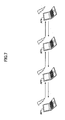
- Fig.1 shows a typical wireless ad-hoc network system.
- Access Points AP1-AP4 are wireless communication devices each functioning as an access point.
- a wireless ad-hoc network is categorized into an ad-hoc based network and a mesh based network.
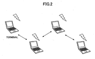
- the ad-hoc based network is composed of wireless LAN terminals only, as shown in Fig.2 .
- the mesh based network is composed of wireless LAN base stations and wireless LAN terminals, as shown in Fig.3 .
- a wireless ad-hoc network system includes both the ad-hoc based network and the mesh based network.
- the access points AP1-AP4 in Fig.1 correspond to the wireless LAN terminals in Fig.2 or the wireless LAN base stations in Fig.3 . If the wireless LAN terminals in Fig.3 include a relay function, they are included in the access points.
- Fig. 1 when one of the access points (nodes) is located so as to communicate data (transfer packets) with the neighbor access points, the access point can communicate data directly with its neighbor access points within its coverage area. That is, data can be communicated directly between AP1 and AP2, between AP2 and AP3, and between AP3 and AP4.
- each of the access points can communicate data indirectly with its non-neighbor access points via intermediate access points. That is, data can be communicated indirectly via the intermediate access points between AP1 and AP4, between AP1 and AP3, and between AP2 and AP4. It is noted that around each of the access points AP1-AP4, there may be terminals (stations) without the relay function, and the terminals may communicate via the access points AP1-AP4.
- Figs.4(a) and (b) show examples of data transmission in accordance with IEEE 802.11, one of the wireless LAN standards.
- the collision avoidance for the data transmission is based on so-called virtual carrier sense.
- Virtual carrier sense See Non-Patent Reference 1, for example, which discloses a wireless LAN system comprising a base station and a terminal.
- Fig.4(a) when the access point AP1 attempts to send data to the access point AP2, the access point AP1 sends the data after a predetermined period called DIFS (Distributed Inter Frame Space) and a random Backoff time(Step S01). In response to the data, the access point AP2 sends an ACK (ACKnowledgement) packet (Step S02).
- DIFS Distributed Inter Frame Space
- ACK ACKnowledgement
- the access point AP1 when the access point AP1 attempts to send data to the access point AP2, the access point AP1 sends a RTS (Request To Send) packet indicating the following data transmission, after the predetermined perid DIFS and the random Backoff time, prior to sending the data (Step S1).
- the access point AP2 In response to the RTS packet, the access point AP2 returns a CTS (Clear To Send) packet which allows the data transmission (Step S2).
- the access point AP1 In response to the CTS packet, the access point AP1 sends data (Step S3), and then access point AP2 returns an ACK packet after receiving the data (Step S4).
- This CTS/CTS mechanism is able to solve a hidden terminal problem.
- the number of data transmissions is limited even if the access point transmits data continuously (not interrupted by another access point data transmission), because the waiting period for Backoff is required for each data transmission.
- Figs.5(a) and (b) show examples of data transmission in accordance with IEEE 802.11e.
- a TXOP Transmission Opportunity
- QoS Quality of Service
- improved efficiency See Non-Patent Reference 2, for example.
- the RTS/CTS is exchanged when the hidden terminal problem mentioned in Fig.4(b) is happening.
- the access point AP1 when the access point AP1 attempts to send data to the access point AP2, the access point AP1 sends a data transmission after the predetermined period DIFS and the random Backoff time (Step S011). In response to the data transmission, the access point AP2 sends the ACK packet as well. However, the access point AP1 can send the next data transmissions continuously during a predetermined duration called "TXOP Limit", upon receiving the ACK packet from the access point AP2.
- TXOP Limit a predetermined duration
- the access point AP1 when the access point AP1 attempts to send data to the access point AP2, the access point AP1 sends the RTS packet to the access point AP2 (Step S11). In response to the RTS packet, the access point AP2 returns the CTS packet which allows the data transmission (Step S12), and then the access point AP1 starts sending data (Step S13) as well. However, the access point AP1 can send the next data transmissions continuously during the predetermined duration "TXOP Limit" (Step S15 and S17), upon receiving the corresponding ACK packets from the access point AP2 (Step S14, S16 and S18).
- TXOP Limit Step S15 and S17
- Non-Patent Reference 1 ANSI/IEEE std 802.11, Wireless LAN medium access control (MAC) and physical layer (PHY) specifications, 1999
- Non-Patent Reference 2 IEEE P802.11e/D9.0, August 2004
- Non-Patent Reference 3 Fusao Nuno, Ichihiko Toyoda, and Masahiro Umehira, "Performance evaluation of QoS Control Scheme that uses back pressure traffic control," PIMRC2004, Vol.2, pp.830-834
- the conventional wireless ad-hoc network system based on the above-mentioned protocol has the following problems.
- each of the access points AP1-AP4 in Fig.1 acquires a transmission opportunity with an equal probability.
- the access points AP2 and AP3 act as relay nodes to relay data for the other access points. Therefore, the access points AP2 and AP3 have a larger amount of data and acquire fewer transmission opportunities compared to the access points AP1 and AP4 located at the left/right ends.
- data may overflow from a transmission buffer (a relay buffer) for storing data to be transmitted, retransmission for the overflowed data may be required, and throughput within the whole wireless ad-hoc network system may be degraded.
- the TXOP aims to improve throughput within the system. Because each of the access points AP1-AP4 transmits a larger amount of data, the data stored in the relay node becomes larger.
- access points AP1-AP3 send data to an access point AP4, and the access point AP4 sends data to access points AP5-AP7.
- the access point AP4 acts as a relay node within the wireless ad-hoc network.
- each of the access points AP1-AP4 acquires the transmission opportunity equally.
- the amount of data to be transmitted from the access point AP4 to the access points AP5-AP7 will be approximately one third of the total amount of data to be transmitted from the access points AP1-AP3 to the access pioint AP4. Therefore, data packets tend to remain at the transmission buffer in the access point AP4 as a relay node, and buffer overflow occurs when the data packets reach the limit of the buffer.
- an access point AP1 sends data to an access point AP4 via access points AP2 and AP3, and at the same time the access point AP4 sends data to the access point AP1 via the access points AP3 and AP2.
- the access points for sending data (AP1 and AP4) send data to their neighbor access points (AP1 sends data to AP2, and AP4 sends data to AP3).
- the access points as relay nodes (AP2 and AP3) need to relay data to plural of their neighbor access points (AP2 sends data to AP1 and AP3, and AP3 sends data to AP2 and AP4). Therefore, the access points as relay nodes (AP2 and AP3) need to acquire more transmission opportunities than the access points for sending data (AP1 and AP4); otherwise, data packets remain at the transmission buffer and accordingly buffer overflow occurs.
- the relay node When buffer overflow occurs within the wireless ad-hoc network, the relay node will discard the data packets communicated via plural relay nodes using wireless resources. Discarding data packets due to buffer overflow wastes the wireless resources. Therefore, buffer overflow in the relay node may cause a serious problem within the wireless ad-hoc network.
- Non-Patent Reference 1 the current wireless LAN standards (such as Non-Patent Reference 1) do not define the technologies to solve the problem of buffer overflow in the relay node. Therefore, the performance in the relay node will be degraded significantly due to buffer overflow, when those standards are applied to the wireless ad-hoc network.
- Non-Patent Reference 3 describes the technology to avoid data packets remaining at the buffer. According to the Non-Patent Reference 3, a field comprising 1 bit is added to the ACK packet transmitted from the relay node. When buffer overflow is likely to occur, the command to decrease the rate is transmitted to the sending node. This technology uses only 1 bit to control traffic for the sending node, and does not take into consideration the amount of data to be transmitted (Packet Transmission Rate) and the amount of data packets at the transmission buffer.
- Packet Transmission Rate Packet Transmission Rate
- US 2002/0154653A discloses collision avoidance in multiple access networks using backoff adaptation to traffic fluctuations.
- a message format includes the number of transmission attempts, and congestion is estimated for each urgency class using this format, which includes the age of the retried transmissions.
- WO 01/95641A discloses a multi-path dynamic routing algorithm in a buffer configured to temporarily store data; a transmitting and receiving unit configured to transmit information related to the amount of data in the buffer to a neighbour wireless communication device and receive information related to the amount of data in a buffer of the neighbour wireless communication device from the neighbour wireless communication device; and a control unit configured to control a transmission rate based on the information related to the amount of data in the buffer of the neighbour wireless communication device.
- the present invention is a device and method as defined in claims 1 and 8.
- the present invention can prevent buffer overflow due to data packets remaining in a relay node within a wireless ad-hoc network system, and can improve throughput within the whole system.
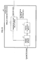
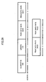
- Fig.8 shows a wireless communication device according to a first embodiment of the present invention.
- the wireless communication device acting as an access point AP includes the following data transmission (data relay) functions: a transmission buffer 1 for temporarily storing data to be transmitted (received signals); a priority control module 2 for transmitting data based on a transmission priority calculated from a priority related parameter (explained below); an association information module 3 for counting the number of stations (STAs) within a coverage area of its own access point AP and the number of neighbor nodes in direct association with its own access point AP, and for acquiring information on the amount of data relay processing; a priority calculation module 4 for calculating the transmission priority of its own access point AP based on the information from the association information module 3, and for determining the priority related parameter of the priority control module 2.
- a transmission buffer 1 for temporarily storing data to be transmitted (received signals)
- a priority control module 2 for transmitting data based on a transmission priority calculated from a priority related parameter (explained below)
- an association information module 3 for counting the number of stations (STAs) within a coverage area
- Fig.9 shows an example of stations within a coverage area of each access point.
- an access point AP1 has three stations (STAs)
- an access point AP2 has six stations
- an access point AP3 has one station
- an access point AP2 has two stations.
- the association information module 3 ( Fig.8 ) in each of the access points AP1-AP4 counts the number of stations within the coverage area of its own access point. Based on the number of stations within the coverage area, the priority calculation module 4 calculates the transmission priority. More specifically, if the number of stations within the coverage area increases, the amount of data relay processing is expected to be increased. In this case, the priority calculation module 4 sets a higher priority, in order to prevent buffer overflow.
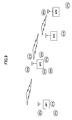
- Fig.10 shows an example of association relationships among access points.
- An access point AP1 has one neighbor node (associated with AP4)
- an access point AP2 has one neighbor node (associated with AP3)
- access point AP3 has two neighbor nodes (associated with AP2 and AP4)
- access point AP4 has three neighbor nodes (associated with AP1, AP3 and AP5)
- access point AP5 has two neighbor access points (associated with AP4 and AP6)
- access point AP6 has one neighbor access point (associated with AP5).
- the association information module 3 ( Fig.8 ) in each of the access points AP1-AP4 counts the number of its neighbor nodes. Based on the number of its neighbor nodes, the priority calculation module 4 calculates the transmission priority. More specifically, if the number of neighbor nodes increases, the amount of data relay processing is expected to be increased. In this case, the priority calculation module 4 sets a higher priority, in order to prevent buffer overflow.
- Controlling the amount of data to be transmitted based on the transmission priority calculated by the priority control module 2 can be achieved by changing an EDCA (Enhanced Distributed Channel Access) parameter defined in IEEE 802.11e.
- the EDCA is a mechanism for QoS.
- the EDCA is used to control transmission traffic.
- Fig.11 shows an EDCA parameter.
- the EDCA parameter for determining the EDCA operation includes AIFS (Arbitrary Inter Frame Space), Backoff and TXOP Limit (Transmission Opportunity Limit).
- AIFS defines a predetermined period necessary to wait before Backoff
- Backoff defines a random time necessary to wait before transmitting the packet
- TXOP Limit defines the duration for which one node can transmit data packets continuously.
- CW (Contention Window) is a fixed value determined from the physical layer, the number of times to be retransmitted, the priority of QoS, etc. Particularly, the CW value before retransmission is called CWmin.
- the default value for CWmin is 31 according to IEEE 802.11. In this case, using 20 ⁇ s of SlotTime, the average Backoff is derived to be 310 ⁇ s.
- TXOP Limit is a fixed value determined from the priority of QoS only. Without QoS, TXOP Limit is not defined and only one packet can be transmitted (plural packets cannot be transmitted continuously).
- the AIFSN parameter smaller, the waiting period before transmitting data will be shorter, and then the transmission priority will be higher.
- the CW parameter smaller, the Backoff time will be shorter, and then the transmission priority will be higher.
- the TXOP Limit parameter longer, the access point can occupy the bandwidth over a longer time period, and then the transmission priority will be higher.
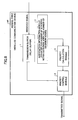
- Fig.12 is a flowchart which illustrates data transmission processing in the first embodiment shown in Fig.8 .
- each access point AP within the wireless ad-hoc network system receives a beacon and the like from the other access points under the control of the association information module 3 (Step S101), and counts the number of stations within the coverage area of the access point AP and the number of neighbor nodes associated with the access point AP (Step S102).
- the priority calculation module 4 calculates the transmission priority based on the number of stations and the number of the access points acquired by the association information module 3, and determines the priority related parameter (CW, AIFSN and/or TXOP Limit) (Step S103).
- the priority control module 2 transmits data held at the transmission buffer 1, based on the priority related parameter (Step S104).
- Fig.13 shows a wireless communication device according to a second embodiment of the present invention.
- the priority calculation module 4 acquires information on the amount of buffered data indicating the amount of data relay processing from a transmission buffer 1. Then, the priority calculation module 4 calculates the transmission priority of its own access point AP based on the information on the amount of buffered data, and determines the priority related parameter of the priority control module 2.
- the other components operate similarly to the components shown in Fig.8 .
- the wireless communication device in Fig.13 may include the association information module 3 in Fig.8 , and use the number of stations, the number of neighbor nodes and the amount of buffered data to determine the priority related parameter in the priority calculation module 4.
- Fig.14 shows an example of the amount of data at the transmission buffer in each access point.
- the amount of buffered data in an access point A3 is largest, that in an access point A2 is the second largest, that in an access point A1 is the third largest, and that in an access point A4 is the smallest.
- Each of the access points AP1-AP4 monitors its own transmission buffer 1 ( Fig.13 ), and the priority calculation module 4 calculates the transmission priority based on the amount of buffered data. More specifically, if the amount of buffered data increases, the amount of data relay processing is expected to be increased. In this case, the priority calculation module 4 sets a higher priority, in order to prevent buffer overflow.
- Fig.15 is a flowchart which illustrates data transmission processing in the second embodiment shown in Fig.13 .
- each access point AP within the wireless ad-hoc network system monitors the amount of data at the transmission buffer (Step S201), and calculates the ratio of the data size to the whole buffer size (Step S202).
- the priority calculation module 4 calculates the transmission priority based on the ratio of the data size to the whole buffer size, and determines the priority related parameter (CW, AIFSN and/or TXOP Limit) (Step S203).
- the priority control module 2 transmits data held at the transmission buffer 1, based on the priority related parameter (Step S204).
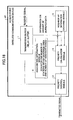
- Fig.16 shows a wireless communication device according to a third embodiment of the present invention.
- a neighbor AP information exchange module 5 exchanges the number of stations within the coverage area, the number of neighbor nodes, and the amount of buffered data in its own access point with a neighbor access point.
- the priority calculation module 4 determines the priority related parameter, considering the number of stations within the coverage area, the number of neighbor nodes, and the amount of bufferd data in both its own access point and the neighbor access point.
- the wireless communication device can determine the transmission priority relative to the other wireless communication devices, and it is possible to adapt the transmission priority to the network conditions.
- Fig.17 is a flowchart which illustrates data transmission processing in the third embodiment shown in Fig.16 .
- each access point AP within the wireless ad-hoc network system transmits the number of stations within the coverage area, the number of its neighbor nodes, and the amount of buffered data (the ratio) acquired by the association information module 3 to the neighbor access point using a beacon and the like (Step S301).
- the neighbor AP information exchange module 5 receives the number of stations within the coverage area, the number of neighbor nodes, and the amount of buffered data in the neighbor access point (Step S302).
- the priority calculation module 4 compares the information acquired from the neighbor access point by the neighbor AP information exchange module 5 with the number of stations, the number of its neighbor nodes, and the amount of buffered data in its own access point acquired by the association information module 3 (Step S303). Based on this total comparison, the priority calculation module 4 calculates the transmission priority and determines the priority related parameter (CW, AIFSN and/or TXOP Limit) (Step S304).
- the priority related parameter CW, AIFSN and/or TXOP Limit
- the priority control module 2 transmits data held at the transmission buffer 1, based on the priority related parameter (Step S305).
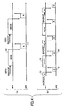
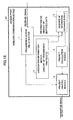
- Fig.18 shows a wireless communication device according to a fourth embodiment of the present invention.
- the neighbor AP information exchange module 5 transmits information on the amount of transmission traffic and the like to the neighbor access point, for example using a signaling mechanism, as a control packet.
- the neighbor AP information exchange module 5 recieves a control packet from the neighbor access point, and the priority calculation module 4 determines the priority related parameter.
- Fig.19 is a flowchart which illustrates flow control in the fourth embodiment. The flowchart is classified into the following three steps.
- the access point which relays data packets constantly monitors the amount of transmission traffic and the number of packets at the transmission buffer (Step S401). Since the amount of transmission traffic and the number of packets at the transmission buffer can change at any time, the relay access point constantly monitors them. Then, the access point which relays data packets transmits the monitored information (the amount of transmission traffic and the number of packets at the transmission buffer) to the associated neighbor access point using a control packet (Step S402).
- the associated neighbor access point When the associated neighbor access point receives the control packet (Step S403), it controls transmission traffic by controlling the above-mentioned EDCA parameter based on the monitored information (the amount of transmission traffic and the number of packets at the transmission buffer in the relay node) included in the control packet.
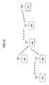
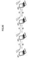
- Fig.20 shows an example of the amount of transmission traffic monitored by each access point.
- Each of access points AP1-AP4 monitors its own transmission traffic.
- the access point AP1 monitors its transmission traffic F1
- the access point AP2 monitors its transmission traffic F2 and R3
- the access point AP3 monitors its transmission traffic F3 and R2
- the access point AP4 monitors its transmission traffic R1.
- Fig.21 shows another example of the amount of transmission traffic monitored by each access point.
- An access point AP1 monitors its transmission traffic F1
- an access point AP2 monitors its transmission traffic F2
- an access point AP3 monitors its transmission traffic F3
- an access point AP4 monitors either transmission traffic F5, F6 and F7 respectively transmitted to access points AP5-AP7 or total transmission traffic F4 (F5+F6+F7).
- monitoring the amount of transmission traffic is achieved by monitoring the number of received ACK packets with respect to the data packets sent from the access point for a certain period of time.
- the access point may use a peak value of the amount of transmission traffic, instead of the amount of transmission traffic for a certain period of time.
- the access point may collect and transmit statistical traffic information for either each priority of QoS or each link for the purpose of accurate flow control. With regard to the period of monitoring, the access point may use the average or the running average for a predetermined period.
- Unicast (1) has an advantage of ensuring the transmission of the signal controlling the transmission rate to the receiver.
- Fig.22 shows an example of a signaling mechanism by means of unicast.
- an access point AP3 sends transmission traffic F3 to an access point AP4 and transmission traffic R2 (in the opposite direction) to an access point AP2, including a FC-Req (Flow Control Request) packet.
- FC-Req Flow Control Request
- the access points AP2 and AP4 receive the FC-Req, they each return a FC-Res (Flow control Response) to the access point AP3.
- This signaling mechanism by means of unicast can ensure communications with the neighbor nodes. However, if the number of nodes associated with the relay node increases, the number of unicast packets is expected to be increased, which may cause degradation in the wireless bandwidth (throughput).
- Fig.23 shows an example of a signaling mechanism by means of a beacon, in which flow control signaling is achieved by adding a new element to the beacon packet broadcast periodically.
- This signaling mechanism is achieved easily, because it adds the new element to the packet instead of defining a new packet for flow control.
- this signaling mechanism has disadvantages in that reliability will be reduced due to broadcasting and flow control for a short period cannot be achieved due to periodic broadcasting.
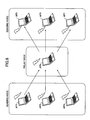
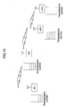
- Fig.24 shows an example of a signaling mechanism in a star topology, in which FC-Req (Flow Control Request) packets are transmitted from a relay access point AP4 to access points AP1-AP3 attempting to send data to this access point AP4.
- FC-Req Flow Control Request
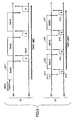
- Fig.25-Fig.28 show example frames used for flow control.
- Each of the frames has the example element included in a packet, and can be applied to both the mechanisms by means of unicast and the mechanisms by means of the beacon.
- a packet shown in Fig.25 has an Element ID, a length of the payload (Length) and the amount of data transmission (Packet Transmission Rate), which are elements used for transmitting the amount of data transmission in the access point to the neighbor node.
- a packet shown in Fig.26 has an Element ID, a length of the payload (Length) and the number of associated nodes (Number of associated MP (Mesh Point)), which are elements used for transmitting the number of associated nodes to the neighbor node, as additional information.
- a packet shown in Fig.27 has an Element ID, a length of the payload (Length), an identifier for links (Associated MP's MAC Address), and the amount of received data (Packet receiving rate), which shows the amount of data received by the node for each link.
- Fig.28 shows an example element including a Peak Data Rate for each priority AC (Access Category) of QoS.
- the packet shown in Fig.28 further includes an Expiration Timer which indicates the time when the node receiving the Flow Control Request packet should control transmission traffic.
- the Flow Control Response is just an ACK (ACKnowledgement) packet.
- the Flow Control Response may include the amount of requested transmission traffic (Offered Load).
- the amount of requested transmission traffic may be transmitted after being categorized into each priority of QoS. In this case, the access point which has the larger amount of requested transmission traffic can be given a higher priority for transmitting data.
- Fig.29 shows an example element indicating the amount of requested transmission traffic for each AC, which can be included in the ACK packet.
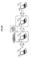
- Fig.30 shows an example of the control of Packet Transmission Rate.
- An access point AP2 controls the transmission rate, using information on the amount of transmission traffic and the number of associated nodes included in a flow control packet received from an access point AP3. For example, when “Offerd Load” in the frame indicates “6 Mbps" and “Number of associated MP on the receiving side” indicates "2", transmission traffic in the access point AP2 should be 3 Mbps (6 Mbps / 2) or less. If transmission traffic is above 3 Mbps, the amount of buffered data in the access point AP3 will be increased. For this reason, the access point AP2 increments the value of AIFSN, in order to decrease transmission traffic.
- AIFSN Packet Transmission Rate
- CWmin and/or TXOP Limit can be changed in order to decrease or increase Packet Transmission Rate.
- Packet Transmission Rate can be decreased or increased significantly, compared to changing AIFSN.
- the control of Packet Transmission Rate using AIFSN can be more moderate than the control using CWmin and/or TXOP Limit.
- AIFSN, CWmin and/or TXOP Limit can be controlled using buffer usage included in the flow control packet. For example, when the buffer usage becomes above half of the buffer capacity while the Packet Transmission Rate at the relay node included in the flow control packet remains below its threshold, it is possible to increase AIFSN and/or CWmin and decrease TXOP Limit to prevent buffer overflow.
- the access point acquires the number of stations within the coverage area, the number of neighbor nodes, and the amount of buffered data, as information on the amount of data relay processing in the own access point (and the other access points, if necessary). Based on the information, the access point calculates the transmission priority and determines the priority related parameter (CW, AIFSN and/or TXOP Limit) for data transmission.
- CW priority related parameter
- AIFSN priority related parameter
- TXOP Limit TXOP Limit
- the present invention can be applied to VoIP (Voice over Internet Protocol) which requires high capacity and short delay, in order to improve performance within the network. VoIP is expected to be used as an application within the wireless ad-hoc network system.
- the access point according to the present invention controls the priority related parameter and does not change its data transmission protocol itself. For this reason, the access point applying the present invention can communicate with an access point that does not apply the present invention. That is, the access point according to the present invention has backward compatibility.
Claims (8)
- Drahtlose Kommunikationsvorrichtung zur Verwendung in einem Relaisknoten innerhalb eines drahtlosen Ad-hoc-Netzwerks oder eines drahtlosen Maschennetzwerks, umfassend:einen Zwischenspeicher (1), der dafür konfiguriert ist, Daten zeitweilig zu speichern;eine Sende- und Empfangseinheit (5), die dafür konfiguriert ist, Information in Bezug auf die Datenmenge im Zwischenspeicher (1) zu einer benachbarten drahtlosen Kommunikationsvorrichtung zu übertragen und Information in Bezug auf die Datenmenge in einem Zwischenspeicher der benachbarten drahtlosen Kommunikationsvorrichtung von der benachbarten drahtlosen Kommunikationsvorrichtung zu empfangen; undeine Steuerungseinheit (2), die dafür konfiguriert ist, eine Übertragungsrate der drahtlosen Kommunikationsvorrichtung auf der Grundlage der Information in Bezug auf die Datenmenge im Zwischenspeicher der benachbarten drahtlosen Kommunikationsvorrichtung zu steuern,wobei die Information in Bezug auf die Datenmenge im Zwischenspeicher der benachbarten drahtlosen Kommunikationsvorrichtung einen Ablaufzeitgeber aufweist, der einen Zeitpunkt angibt, wann die Steuerungseinheit die Übertragungsrate der drahtlosen Kommunikationsvorrichtung steuern sollte.
- Drahtlose Kommunikationsvorrichtung nach Anspruch 1, wobei:die Sende- und Empfangseinheit (5) dafür konfiguriert ist, die Information in Bezug auf die Datenmenge im Zwischenspeicher (1) zu der benachbarten drahtlosen Kommunikationsvorrichtung mittels eines Signals zu übertragen, das Übertragungsratensteuerung anfordert.
- Drahtlose Kommunikationsvorrichtung nach Anspruch 1, wobei:die Sende und Empfangseinheit (5) dafür konfiguriert ist, die Information in Bezug auf die Datenmenge im Zwischenspeicher der benachbarten drahtlosen Kommunikationsvorrichtung von der benachbarten drahtlosen Kommuntikationsworrichtung mittels eines Signals zu empfangen, mit dem Übertragungsratensteuerung angefordert wird.
- Drahtlose Kommunikationsvorrichtung nach Anspruch 1, wobei:die Sende- und Empfangseinheit (5) dafür konfiguriert ist, die Information in Bezug auf die Datenmenge im Zwischenspeicher (1) zu der benachbarten drahtlosen Kommunikationsvorrichtung zu übertragen, wobei die Information in Bezug auf die Datenmenge nach der jeweiligen Priorität kategorisiert ist.
- Drahtlose Kommunikationsvorrichtung nach Anspruch 1, wobei:die Sende- und Empfangseinheit (5) dafür konfiguriert ist, die Information in Bezug auf die Datenmenge im Zwischenspeicher der benachbarten drahtlosen Kommunikationsvorrichtung von der benachbarten drahtlosen Kommunikationsvorrichtung zu empfangen, wobei die Information in Bezug auf die Datenmenge nach der jeweiligen Priorität kategorisiert ist, unddie Steuerungseinheit (2) dafür konfiguriert ist, die Übertragungsrate auf der Grundlage der Information in Bezug auf die Datenmenge im Zwischenspeicher der benachbarten drahtlosen Kommunikationsvorrichtung zu steuern, wobei die Information in Bezug auf die Datenmenge nach der jeweiligen Priorität kategorisiert ist.
- Drahtlose Kommunikationsvorrichtung nach Anspruch 1, wobei:die Steuerungseinheit (2) dafür konfiguriert ist, die Übertragungsrate durch Ändern eines EDCA-Parameters zu steuern.
- Drahtloses Ad-hoc-Netzwerk mit einer Vielzahl von drahtlosen Kommunikationsvorrichtungen, jeweils nach einem der vorhergehenden Ansprüche.
- Drahtloses Kommunikationsverfahren, durchgeführt durch eine drahtlose Kommunikationsvorrichtung zur Verwendung in einem Relaisknoten innerhalb eines drahtlosen Ad-hoc-Netzwerks oder eines drahtlosen Maschennetzwerks, umfassend:zeitweiliges Speichern von Daten in einem Zwischenspeicher (1);Übertragen von Information in Bezug auf die Datenmenge im Zwischenspeicher (1) zu einer benachbarten drahtlosen Kommunikationsvorrichtung und Empfangen von Information in Bezug auf die Datenmenge in einem Zwischenspeicher der benachbarten drahtlosen Kommunikationsvorrichtung; undSteuern der Übertragungsrate der drahtlosen Kommunikationsvorrichtung auf der Grundlage der Information in Bezug auf die Datenmenge im Zwischenspeicher der benachbarten drahtlosen Kommunikationsvorrichtung,wobei die Information in Bezug auf die Datenmenge im Zwischenspeicher der benachbarten drahtlosen Kommunikationsvorrichtung einen Ablaufzeitgeber aufweist, der einen Zeitpunkt angibt, wann die Übertragungsrate der drahtlosen Kommunikationsvorrichtung gesteuert werden sollte.
Applications Claiming Priority (2)
| Application Number | Priority Date | Filing Date | Title |
|---|---|---|---|
| JP2004254595 | 2004-09-01 | ||
| JP2005156395A JP4718242B2 (ja) | 2004-09-01 | 2005-05-27 | 無線通信装置、無線通信システムおよび無線通信方法 |
Publications (3)
| Publication Number | Publication Date |
|---|---|
| EP1646190A2 EP1646190A2 (de) | 2006-04-12 |
| EP1646190A3 EP1646190A3 (de) | 2009-04-22 |
| EP1646190B1 true EP1646190B1 (de) | 2011-08-10 |
Family
ID=35809618
Family Applications (1)
| Application Number | Title | Priority Date | Filing Date |
|---|---|---|---|
| EP20050255282 Active EP1646190B1 (de) | 2004-09-01 | 2005-08-26 | Eine drahtlose Kommunikationsvorrichtung, ein drahtloses Kommunikationssystem und ein drahtloses Kommunikationsverfahren mit einer variablen Datenübertragungsrate |
Country Status (3)
| Country | Link |
|---|---|
| US (1) | US7813275B2 (de) |
| EP (1) | EP1646190B1 (de) |
| JP (1) | JP4718242B2 (de) |
Families Citing this family (54)
| Publication number | Priority date | Publication date | Assignee | Title |
|---|---|---|---|---|
| US8027327B2 (en) | 2004-06-25 | 2011-09-27 | Alcatel Lucent | Distributed scheduling in wireless networks with service differentiation |
| EP1845666A1 (de) * | 2005-02-02 | 2007-10-17 | Matsushita Electric Industrial Co., Ltd. | Pakettransferverfahren in einem kommunikations-netzwerksystem und paketverarbeitungsverfahren in einer kommunikationseinrichtung, wodurch das system gebildet wird |
| US9131371B2 (en) * | 2005-09-30 | 2015-09-08 | Alcatel Lucent | Method and apparatus for managing a random access communication system |
| US9521584B2 (en) * | 2005-10-17 | 2016-12-13 | Qualcomm Incorporated | Method and apparatus for managing data flow through a mesh network |
| US8605579B2 (en) * | 2005-10-17 | 2013-12-10 | Qualcomm Incorporated | Method and apparatus for flow control of data in a mesh network |
| JP4799213B2 (ja) * | 2006-02-28 | 2011-10-26 | 株式会社エヌ・ティ・ティ・ドコモ | 無線通信端末及び無線通信方法 |
| US20070214379A1 (en) * | 2006-03-03 | 2007-09-13 | Qualcomm Incorporated | Transmission control for wireless communication networks |
| US7978725B2 (en) * | 2006-03-06 | 2011-07-12 | Cisco Technology, Inc. | Dynamic modification of contention-based transmission control parameters achieving load balancing scheme in wireless mesh networks |
| US7969878B2 (en) * | 2006-04-28 | 2011-06-28 | Siemens Enterprise Communications Gmbh & Co. Kg | Quality guarantee for real-time applications over shared networks |
| CN101502059B (zh) * | 2006-08-07 | 2014-07-09 | 高通股份有限公司 | 用于异步无线通信的消息交换方案 |
| US9008002B2 (en) | 2006-08-07 | 2015-04-14 | Qualcomm Incorporated | Conditional requests for asynchronous wireless communication |
| JP2008072381A (ja) * | 2006-09-13 | 2008-03-27 | Toshiba Corp | 基地局、移動体通信システム、及びチャネル割当方法 |
| US20080144588A1 (en) * | 2006-12-14 | 2008-06-19 | Amir Mezer | Method and apparatus of prioritizing services of wireless local area network |
| CN101009652A (zh) * | 2007-01-23 | 2007-08-01 | 中兴通讯股份有限公司 | 以太网无源光网络下行流控信息传递方法 |
| JP4384675B2 (ja) | 2007-02-14 | 2009-12-16 | 日本電気通信システム株式会社 | 無線装置およびそれを用いた無線ネットワーク |
| EP1962456B1 (de) * | 2007-02-21 | 2009-08-19 | NTT DoCoMo Inc. | Sende/Empfangsgerät für kooperative drahtlose Netzwerke |
| US9807803B2 (en) * | 2007-03-01 | 2017-10-31 | Qualcomm Incorporated | Transmission control for wireless communication networks |
| US7978636B2 (en) * | 2007-03-27 | 2011-07-12 | Hitachi, Ltd. | System and method for controlling throughput of access classes in a WLAN |
| AU2007201693C1 (en) * | 2007-04-11 | 2016-09-29 | Ess Engineering Services & Supplies Pty Limited | A conveyor belt cleaner blade |
| US9497229B2 (en) * | 2007-05-16 | 2016-11-15 | At&T Intellectual Property I, L.P. | Methods and apparatus to manage internet protocol (IP) multimedia subsystem (IMS) network capacity |
| US8184538B2 (en) * | 2007-06-22 | 2012-05-22 | At&T Intellectual Property I, L.P. | Regulating network service levels provided to communication terminals through a LAN access point |
| US20080316983A1 (en) * | 2007-06-22 | 2008-12-25 | At&T Intellectual Property, Inc. | Service information in a LAN access point that regulates network service levels provided to communication terminals |
| US8300618B2 (en) | 2007-07-20 | 2012-10-30 | Motorola Solutions, Inc. | User priority based preemption techniques in a time division multiple access multi-hop ad hoc network |
| JP2009060213A (ja) * | 2007-08-30 | 2009-03-19 | Sony Corp | 無線通信装置、無線通信システム、無線通信方法及びプログラム |
| JP4986155B2 (ja) * | 2007-10-15 | 2012-07-25 | 横河電機株式会社 | 通信品質診断装置 |
| US8767541B2 (en) | 2008-02-14 | 2014-07-01 | Qualcomm Incorporated | Scheduling policy-based traffic management |
| US8964651B2 (en) | 2008-02-14 | 2015-02-24 | Qualcomm Incorporated | Traffic management employing interference management messages |
| US8737314B2 (en) * | 2008-02-14 | 2014-05-27 | Qualcomm Incorporated | Traffic management for multi-hop wireless communication |
| US8477674B2 (en) * | 2008-03-12 | 2013-07-02 | Nokia Corporation | Wireless network including post groupcast time |
| US8274894B2 (en) * | 2008-05-07 | 2012-09-25 | Nokia Corporation | Quality of service and power aware forwarding rules for mesh points in wireless mesh networks |
| US9467308B2 (en) * | 2008-08-01 | 2016-10-11 | At&T Intellectual Property I, L.P. | Methods and apparatus to control synchronization in voice over internet protocol networks after catastrophes |
| JP5141570B2 (ja) | 2009-01-20 | 2013-02-13 | 富士通株式会社 | 無線アドホックネットワークのための無線通信機 |
| US8285900B2 (en) | 2009-02-17 | 2012-10-09 | The Board Of Regents Of The University Of Texas System | Method and apparatus for congestion-aware routing in a computer interconnection network |
| EP2244516B1 (de) * | 2009-04-23 | 2016-05-18 | Alcatel Lucent | Weiterleiten von Daten zwischen einer Basisstation und einem Teilnehmergerät |
| US9584416B2 (en) | 2009-06-08 | 2017-02-28 | Qualcomm Incorporated | Systems and methods to provide flow control for mobile devices |
| JP2011010018A (ja) * | 2009-06-25 | 2011-01-13 | Oki Electric Industry Co Ltd | 通信制御装置及びプログラム |
| US8948806B2 (en) * | 2009-07-02 | 2015-02-03 | Empire Technology Development Llc | Loss differentiation based management of wireless networks |
| CN102474748B (zh) * | 2009-09-29 | 2014-06-04 | 上海贝尔股份有限公司 | 调度方法和调度器 |
| US9226323B2 (en) * | 2011-01-14 | 2015-12-29 | Electronics And Telecommunications Research Institute | Method and apparatus for transmitting relay frame in wireless communication system |
| WO2012127597A1 (ja) | 2011-03-19 | 2012-09-27 | 富士通株式会社 | 輻輳制御方法および無線通信装置 |
| US9247482B2 (en) * | 2011-08-03 | 2016-01-26 | Harris Corporation | Ad hoc wireless communications network with node role information routing and associated methods |
| WO2013098255A1 (en) * | 2011-12-29 | 2013-07-04 | Thomson Licensing | A network gateway and a method for transmitting packets of a data stream |
| US9131519B2 (en) * | 2012-12-20 | 2015-09-08 | Broadcom Corporation | Communications coexistence signaling |
| US9854991B2 (en) | 2013-03-15 | 2018-01-02 | Medtronic Navigation, Inc. | Integrated navigation array |
| CN105340350B (zh) | 2013-07-02 | 2019-03-22 | Kt株式会社 | 在无线lan系统中的信道接入方法及装置 |
| KR20150111732A (ko) * | 2014-03-26 | 2015-10-06 | 한국전자통신연구원 | 동시 전송을 이용한 데이터 통신 장치 및 방법 |
| JP6185882B2 (ja) * | 2014-05-20 | 2017-08-23 | 日本電信電話株式会社 | アクセスポイント装置 |
| US20160192377A1 (en) * | 2014-12-30 | 2016-06-30 | Qualcomm Incorporated | Adaptive edca adjustment for dynamic sensitivity control |
| JP6953896B2 (ja) * | 2017-08-23 | 2021-10-27 | 富士通株式会社 | 通信装置、通信システム、通信方法、及び通信プログラム |
| JP6882684B2 (ja) * | 2017-09-04 | 2021-06-02 | 富士通株式会社 | 通信装置、通信システム、通信制御方法、及び通信制御プログラム |
| CN111602122B (zh) | 2018-01-19 | 2023-08-22 | 三菱电机株式会社 | 通信控制装置、通信控制方法和计算机能读取的存储介质 |
| US11057748B1 (en) * | 2018-09-17 | 2021-07-06 | Synapse Wireless, Inc. | Prioritized communication windows in a wireless mesh network |
| JP7039447B2 (ja) * | 2018-11-29 | 2022-03-22 | 株式会社東芝 | 無線通信装置、無線通信方法及びプログラム |
| TWI789116B (zh) * | 2021-11-15 | 2023-01-01 | 瑞昱半導體股份有限公司 | 具有資料流傳輸排序機制的網格網路系統及其通訊方法 |
Family Cites Families (34)
| Publication number | Priority date | Publication date | Assignee | Title |
|---|---|---|---|---|
| JP2705686B2 (ja) | 1996-01-26 | 1998-01-28 | 日本電気株式会社 | 無線データ通信方式 |
| US6452933B1 (en) * | 1997-02-07 | 2002-09-17 | Lucent Technologies Inc. | Fair queuing system with adaptive bandwidth redistribution |
| US6026075A (en) * | 1997-02-25 | 2000-02-15 | International Business Machines Corporation | Flow control mechanism |
| JP3733784B2 (ja) * | 1999-05-21 | 2006-01-11 | 株式会社日立製作所 | パケット中継装置 |
| US6618378B1 (en) * | 1999-07-21 | 2003-09-09 | Alcatel Canada Inc. | Method and apparatus for supporting multiple class of service connections in a communications network |
| JP3586788B2 (ja) * | 1999-09-14 | 2004-11-10 | 株式会社日立製作所 | 無線ネットワーク |
| US6438135B1 (en) * | 1999-10-21 | 2002-08-20 | Advanced Micro Devices, Inc. | Dynamic weighted round robin queuing |
| ATE430423T1 (de) * | 2000-06-07 | 2009-05-15 | Intel Corp | Dynamischer mehrwege-routing-algorithmus |
| KR100428309B1 (ko) * | 2000-09-30 | 2004-04-30 | 엘지전자 주식회사 | 라우터의 적응적 폴링방법 |
| US20020059408A1 (en) * | 2000-11-02 | 2002-05-16 | Krishna Pattabhiraman | Dynamic traffic management on a shared medium |
| JP2002171572A (ja) * | 2000-12-01 | 2002-06-14 | Hitachi Ltd | 無線基地局、パケット中継装置並びに無線通信システム |
| US7027462B2 (en) * | 2001-01-02 | 2006-04-11 | At&T Corp. | Random medium access methods with backoff adaptation to traffic |
| US7110359B1 (en) * | 2001-03-05 | 2006-09-19 | Advanced Micro Devices, Inc. | System and method for dynamically updating weights of weighted round robin in output queues |
| US20020159460A1 (en) * | 2001-04-30 | 2002-10-31 | Carrafiello Michael W. | Flow control system to reduce memory buffer requirements and to establish priority servicing between networks |
| US8213322B2 (en) * | 2001-09-24 | 2012-07-03 | Topside Research, Llc | Dynamically distributed weighted fair queuing |
| US20030081603A1 (en) * | 2001-10-26 | 2003-05-01 | Johan Rune | Pending data announcements |
| US7062568B1 (en) * | 2002-01-31 | 2006-06-13 | Forcelo Networks, Inc. | Point-to-point protocol flow control extension |
| JP3898965B2 (ja) * | 2002-03-06 | 2007-03-28 | 株式会社エヌ・ティ・ティ・ドコモ | 無線リソース割り当て方法及び基地局 |
| US20040125815A1 (en) * | 2002-06-24 | 2004-07-01 | Mikio Shimazu | Packet transmission apparatus and method thereof, traffic conditioner, priority control mechanism and packet shaper |
| JP2004147275A (ja) * | 2002-08-30 | 2004-05-20 | Matsushita Electric Ind Co Ltd | パケット送信スケジューリング方法および基地局装置 |
| JP3733943B2 (ja) * | 2002-10-16 | 2006-01-11 | 日本電気株式会社 | データ転送速度調停システム及びそれに用いるデータ転送速度調停方法 |
| JP4058326B2 (ja) * | 2002-10-17 | 2008-03-05 | 株式会社エヌ・ティ・ティ・ドコモ | 無線基地局、制御装置、無線通信システム及び通信方法 |
| JP2004187237A (ja) * | 2002-12-06 | 2004-07-02 | Matsushita Electric Ind Co Ltd | 基地局装置およびパケット送信スケジューリング方法 |
| US7047310B2 (en) * | 2003-02-25 | 2006-05-16 | Motorola, Inc. | Flow control in a packet data communication system |
| JP5054377B2 (ja) * | 2003-06-06 | 2012-10-24 | メッシュネットワークス インコーポレイテッド | アドホック・ネットワークにおけるフェアネスおよびサービスの差別化を実現するシステムおよび方法 |
| US7295519B2 (en) * | 2003-06-20 | 2007-11-13 | Motorola, Inc. | Method of quality of service based flow control within a distributed switch fabric network |
| US7245946B2 (en) * | 2003-07-07 | 2007-07-17 | Texas Instruments Incorporated | Optimal power saving scheduler for 802.11e APSD |
| US7480248B2 (en) * | 2003-08-22 | 2009-01-20 | Samsung Electronics Co., Ltd. | Apparatus and method for determining aggregated link costs in a mobile ad hoc network |
| US7385920B2 (en) * | 2003-09-15 | 2008-06-10 | Qualcomm Incorporated | Flow admission control for wireless systems |
| US7706403B2 (en) * | 2003-11-25 | 2010-04-27 | Telefonaktiebolaget Lm Ericsson (Publ) | Queuing delay based rate control |
| EP1714435A1 (de) * | 2004-02-09 | 2006-10-25 | Research In Motion Limited | Verfahren und vorrichtungen zur steuerung von mit einem flusssteuerprozess assoziierten operationen eines drahtlosen netzwerks |
| US20050185583A1 (en) * | 2004-02-19 | 2005-08-25 | Hosein Patrick A. | QoS management for multiple service instances |
| US7724750B2 (en) * | 2004-04-01 | 2010-05-25 | Nokia Corporation | Expedited data transmission in packet based network |
| WO2005107292A1 (en) * | 2004-04-28 | 2005-11-10 | Nortel Networks Limited | Independent scheduling in a wireless network |
-
2005
- 2005-05-27 JP JP2005156395A patent/JP4718242B2/ja active Active
- 2005-08-26 EP EP20050255282 patent/EP1646190B1/de active Active
- 2005-08-29 US US11/212,785 patent/US7813275B2/en active Active
Non-Patent Citations (1)
| Title |
|---|
| CAMPBELL A.T. ET AL: "Supporting service differentiation for real-time and best-effort traffic in stateless wireless ad hoc networks (SWAN)", IEEE TRANSACTIONS ON MOBILE COMPUTING, vol. 1, no. 3, 1 July 2002 (2002-07-01), IEEE SERVICE CENTER, LOS ALAMITOS, CA, US, pages 192 - 207, XP011095348 * |
Also Published As
| Publication number | Publication date |
|---|---|
| JP4718242B2 (ja) | 2011-07-06 |
| US7813275B2 (en) | 2010-10-12 |
| JP2006101477A (ja) | 2006-04-13 |
| US20060056382A1 (en) | 2006-03-16 |
| EP1646190A3 (de) | 2009-04-22 |
| EP1646190A2 (de) | 2006-04-12 |
Similar Documents
| Publication | Publication Date | Title |
|---|---|---|
| EP1646190B1 (de) | Eine drahtlose Kommunikationsvorrichtung, ein drahtloses Kommunikationssystem und ein drahtloses Kommunikationsverfahren mit einer variablen Datenübertragungsrate | |
| EP1430619B1 (de) | Ssystgem und Verfahren zur Verwendung von Algorithmen und Protokollen zur optimierung von CSMA-Protokollen (Carrier Sense Multiple Access) in drahtlosen Netzwerken | |
| KR100823467B1 (ko) | 애드 혹 네트워크들에서 공평성 및 서비스 차별성을 제공하기 위한 시스템 및 방법 | |
| US7733766B2 (en) | System and method for providing quality of service provisions and congestion control in a wireless communication network | |
| US7027462B2 (en) | Random medium access methods with backoff adaptation to traffic | |
| CN100407678C (zh) | 无线通信装置、无线通信系统和无线通信方法 | |
| Choi et al. | Multi-channel MAC protocol for mobile ad hoc networks | |
| JP4734227B2 (ja) | Wlanにおける帯域プロビジョニング方法及び装置 | |
| US7542478B1 (en) | System and method for rate limiting in multi-hop wireless ad hoc networks | |
| US20080240049A1 (en) | System and method for controlling throughput of access classes in a wlan | |
| US8077665B2 (en) | Bandwidth allocation in a wireless network | |
| JP4750644B2 (ja) | 無線システム、無線通信装置及び通信方法 | |
| Abdalla et al. | Space-orthogonal frequency-time medium access control (SOFT MAC) for VANET | |
| Aad et al. | Remarks on per-flow differentiation in IEEE 802.11 | |
| Li et al. | ECS: An enhanced carrier sensing mechanism for wireless ad hoc networks | |
| US20120127981A1 (en) | Method and device for sending packets on a wireless local area network | |
| WO2009154581A1 (en) | Wireless local area networking devices providing protection for high priority packets | |
| Moad et al. | Padovan sequence based Backoff Algorithm for improved wireless medium access in MANETs | |
| EP1708382A1 (de) | Algorithmen und Protokolle zur Optimierung von CSMA-Protokollen (Carrier Sense Multiple Access) in drahtlosen Netzwerken | |
| JP2008211600A (ja) | 無線通信システム、通信装置及び通信制御方法 | |
| Le | Back-Pressure Based Throughput Enhancement Algorithms for Cognitive Radio Networks | |
| EP1783957A1 (de) | Bandbreitenzuteilung in einem drahtlosen Netzwerk | |
| Nuno et al. | Performance evaluation of QoS control scheme that uses back pressure traffic control | |
| Duvvuru et al. | Persistence based cooperative MAC protocol for Ad Hoc wireless networks | |
| Saraireh et al. | A comparative study of IEEE 802.11 MAC access mechanisms for different traffic types |
Legal Events
| Date | Code | Title | Description |
|---|---|---|---|
| PUAI | Public reference made under article 153(3) epc to a published international application that has entered the european phase |
Free format text: ORIGINAL CODE: 0009012 |
|
| 17P | Request for examination filed |
Effective date: 20050914 |
|
| AK | Designated contracting states |
Kind code of ref document: A2 Designated state(s): AT BE BG CH CY CZ DE DK EE ES FI FR GB GR HU IE IS IT LI LT LU LV MC NL PL PT RO SE SI SK TR |
|
| AX | Request for extension of the european patent |
Extension state: AL BA HR MK YU |
|
| PUAL | Search report despatched |
Free format text: ORIGINAL CODE: 0009013 |
|
| AK | Designated contracting states |
Kind code of ref document: A3 Designated state(s): AT BE BG CH CY CZ DE DK EE ES FI FR GB GR HU IE IS IT LI LT LU LV MC NL PL PT RO SE SI SK TR |
|
| AX | Request for extension of the european patent |
Extension state: AL BA HR MK YU |
|
| RIC1 | Information provided on ipc code assigned before grant |
Ipc: H04L 12/56 20060101AFI20090313BHEP |
|
| AKX | Designation fees paid |
Designated state(s): DE GB |
|
| 17Q | First examination report despatched |
Effective date: 20091222 |
|
| RTI1 | Title (correction) |
Free format text: A WIRELESS COMMUNICATION DEVICE, A WIRELESS COMMUNICATION SYSTEM AND A WIRELESS COMMUNICATION METHOD USING A VARIABLE DATA TRANSMISSION RATE |
|
| GRAP | Despatch of communication of intention to grant a patent |
Free format text: ORIGINAL CODE: EPIDOSNIGR1 |
|
| RIN1 | Information on inventor provided before grant (corrected) |
Inventor name: YAMADA, AKIRA C/O INTELLECTUAL PROPERTY DPT. Inventor name: FUJIWARA, ATSUSHI C/O INTELLECTUAL PROPERTY DPT. |
|
| GRAS | Grant fee paid |
Free format text: ORIGINAL CODE: EPIDOSNIGR3 |
|
| GRAA | (expected) grant |
Free format text: ORIGINAL CODE: 0009210 |
|
| AK | Designated contracting states |
Kind code of ref document: B1 Designated state(s): DE GB |
|
| REG | Reference to a national code |
Ref country code: GB Ref legal event code: FG4D |
|
| REG | Reference to a national code |
Ref country code: DE Ref legal event code: R096 Ref document number: 602005029406 Country of ref document: DE Effective date: 20111006 |
|
| PLBE | No opposition filed within time limit |
Free format text: ORIGINAL CODE: 0009261 |
|
| STAA | Information on the status of an ep patent application or granted ep patent |
Free format text: STATUS: NO OPPOSITION FILED WITHIN TIME LIMIT |
|
| 26N | No opposition filed |
Effective date: 20120511 |
|
| REG | Reference to a national code |
Ref country code: DE Ref legal event code: R097 Ref document number: 602005029406 Country of ref document: DE Effective date: 20120511 |
|
| P01 | Opt-out of the competence of the unified patent court (upc) registered |
Effective date: 20230509 |
|
| PGFP | Annual fee paid to national office [announced via postgrant information from national office to epo] |
Ref country code: GB Payment date: 20230824 Year of fee payment: 19 |
|
| PGFP | Annual fee paid to national office [announced via postgrant information from national office to epo] |
Ref country code: DE Payment date: 20230821 Year of fee payment: 19 |