EP1645839A1 - Dispositif et procédé pour surveiller des objets en motion - Google Patents
Dispositif et procédé pour surveiller des objets en motion Download PDFInfo
- Publication number
- EP1645839A1 EP1645839A1 EP05020110A EP05020110A EP1645839A1 EP 1645839 A1 EP1645839 A1 EP 1645839A1 EP 05020110 A EP05020110 A EP 05020110A EP 05020110 A EP05020110 A EP 05020110A EP 1645839 A1 EP1645839 A1 EP 1645839A1
- Authority
- EP
- European Patent Office
- Prior art keywords
- optical sensor
- evaluation circuit
- objects
- optical
- interest
- Prior art date
- Legal status (The legal status is an assumption and is not a legal conclusion. Google has not performed a legal analysis and makes no representation as to the accuracy of the status listed.)
- Granted
Links
- 238000000034 method Methods 0.000 title claims abstract description 14
- 230000000007 visual effect Effects 0.000 claims abstract description 10
- 238000011156 evaluation Methods 0.000 claims description 93
- 230000003287 optical effect Effects 0.000 claims description 93
- 230000006835 compression Effects 0.000 claims description 9
- 238000007906 compression Methods 0.000 claims description 9
- 238000011144 upstream manufacturing Methods 0.000 claims description 5
- 239000011159 matrix material Substances 0.000 claims description 2
- 238000001514 detection method Methods 0.000 description 6
- 238000005286 illumination Methods 0.000 description 6
- 230000008901 benefit Effects 0.000 description 5
- 230000008569 process Effects 0.000 description 4
- 238000007781 pre-processing Methods 0.000 description 3
- 238000004364 calculation method Methods 0.000 description 2
- 230000006855 networking Effects 0.000 description 2
- 230000002411 adverse Effects 0.000 description 1
- 238000010276 construction Methods 0.000 description 1
- 230000001419 dependent effect Effects 0.000 description 1
- 238000010586 diagram Methods 0.000 description 1
- 230000000694 effects Effects 0.000 description 1
- 238000012432 intermediate storage Methods 0.000 description 1
- 238000001454 recorded image Methods 0.000 description 1
- 230000009467 reduction Effects 0.000 description 1
- 238000002310 reflectometry Methods 0.000 description 1
- 230000008672 reprogramming Effects 0.000 description 1
- 230000009466 transformation Effects 0.000 description 1
- 230000032258 transport Effects 0.000 description 1
Images


Classifications
-
- G—PHYSICS
- G01—MEASURING; TESTING
- G01B—MEASURING LENGTH, THICKNESS OR SIMILAR LINEAR DIMENSIONS; MEASURING ANGLES; MEASURING AREAS; MEASURING IRREGULARITIES OF SURFACES OR CONTOURS
- G01B11/00—Measuring arrangements characterised by the use of optical techniques
- G01B11/02—Measuring arrangements characterised by the use of optical techniques for measuring length, width or thickness
- G01B11/04—Measuring arrangements characterised by the use of optical techniques for measuring length, width or thickness specially adapted for measuring length or width of objects while moving
-
- B—PERFORMING OPERATIONS; TRANSPORTING
- B07—SEPARATING SOLIDS FROM SOLIDS; SORTING
- B07C—POSTAL SORTING; SORTING INDIVIDUAL ARTICLES, OR BULK MATERIAL FIT TO BE SORTED PIECE-MEAL, e.g. BY PICKING
- B07C3/00—Sorting according to destination
- B07C3/10—Apparatus characterised by the means used for detection ofthe destination
- B07C3/14—Apparatus characterised by the means used for detection ofthe destination using light-responsive detecting means
-
- G—PHYSICS
- G01—MEASURING; TESTING
- G01B—MEASURING LENGTH, THICKNESS OR SIMILAR LINEAR DIMENSIONS; MEASURING ANGLES; MEASURING AREAS; MEASURING IRREGULARITIES OF SURFACES OR CONTOURS
- G01B11/00—Measuring arrangements characterised by the use of optical techniques
Definitions
- the invention relates to an apparatus and a method for detecting objects moving through the visual field of an optical sensor, having means for selecting areas of interest which are each associated with only a part of the field of view of the optical sensor.
- the ROIs have been defined by means of the preprocessing stage, it is possible within the scope of the actual evaluation circuit to process only the captured image data of these ROIs, which requires correspondingly less processing power than the processing of the complete images recorded by the optical sensor or by the camera ,
- the ROIs are determined by preprocessing the complete acquired image data, simple algorithms being used here on the basis of the high image data stream, which only determine, for example, whether the gray value of a pixel is above a predetermined threshold value. If this is the case, the checked pixel is assigned to a ROI, otherwise it will not be taken into account in the further evaluation.
- One of the disadvantages of such algorithms is that the respective condition, in the aforementioned example the exceeding of a predetermined threshold, is not always reliably fulfilled, since, for example, an object of interest to be detected is not always brighter than the background surrounding the object , In such cases, the mentioned algorithms can not or only partially be used.
- a device having the features of claim 1 and in particular in that a rangefinder is integrated into the optical sensor or this upstream or downstream in the direction of movement of the objects that the rangefinder for determining the distances of the Rangefinder facing object surfaces designed and equipped with an evaluation circuit to calculate the areas of interest in Depending on the determined distances is coupled, and that the evaluation circuit is designed to determine the resolution or the magnification factor of the images detected by the optical sensor.
- this object is achieved according to the first variant of the invention by a method having the features of claim 20 and in particular that with a built in the optical sensor or this in the direction of movement of the objects upstream or downstream rangefinder, the distances of the rangefinder facing object surfaces are determined , whereupon by means of an evaluation circuit, the regions of interest are calculated as a function of the determined distances, wherein the resolution or the magnification factor of the images detected by the optical sensor is determined by the evaluation circuit.
- the image data determined by the optical sensor are not used at all to determine the ROIs, but instead a separate device, namely a rangefinder, is used to determine the ROIs, which is capable of determining its distance from the object surfaces facing it , Then, if the distance between the range finder and the surface on which the objects to be detected rest are still known, the positions of those rangefinder detected areas can be easily determined where the determined distance does not coincide with the distance to the background. These areas are then ROIs in which an object exists.
- the position information of the ROIs determined in the manner according to the invention can then be used in the context of the evaluation circuit only still evaluate those captured by the optical sensor image content that are assigned to the previously determined ROIs.
- the resolution or the magnification factor of the images captured by the optical sensor are calculated from the distances provided by the rangefinder, so that it is known, for example with further processing of the ROIs, with which dpi resolution the images captured by the optical sensor are present. If, for example, existing letters or numbers in the ROIs which have absolute values defined on the detected objects are then to be recognized by means of automated image processing algorithms, information is available to the respective image processing algorithm as to which size, measured in pixels of the captured images, increases possessing recognizable letters or numbers. As a result, the efficiency of the respective image processing algorithm can be improved.
- the evaluation circuit used according to all variants of the invention can be a separate component, but also a component of the optical sensor or of the distance and / or remission meter.
- the evaluation circuit can represent a single component which calculates both the regions of interest and the resolution or the magnification factor.
- separate, spatially separated components of the evaluation circuit can be used for the calculation of the areas of interest.
- the computing power of the evaluation circuit can be designed in all variants according to the invention so that it is capable of processing the image data of the ROIs in the respectively required speed, if necessary in real time. A higher computing power is not required, since the ROIs - as mentioned - according to the invention can be determined to a certain extent without stress on the computing capacity of the evaluation circuit.
- the evaluation circuit is preferably designed to determine the geometry of the objects as a function of the determined distances.
- information about the size of the detected objects or about their shape can then also be made available for the purpose of suitable further processing.
- the volume of each detected object can also be determined via the evaluation circuit as a function of the determined distances.
- the above object can also be achieved according to a second variant of the invention by a device having the features of claim 5 and in particular by the fact that a distance and / or remission meter integrated in the optical sensor or upstream or downstream thereof in the direction of movement of the objects, that the distance and / or remission meter designed to determine the distances and / or remissions of the distance and / or remission knife facing object surfaces and with an evaluation circuit for calculating the areas of interest in dependence is coupled by the determined distances and / or remissions, and that at least two optical sensors are provided, which detect the moving objects from different angles.
- a remission knife can be used here alternatively or in addition to the rangefinder, so that in this case the ROIs can be determined as a function of the remission behavior of the object surfaces.
- ROIs can be identified as those areas in which the remission behavior does not coincide with the remission behavior of background areas.
- two or more optical sensors are used to detect the objects from different angles. This is particularly advantageous, for example, when ROIs to be detected are arranged on an object surface facing away from a sensor. Such ROIs can then be detected by the at least one further sensor, so that the reliable detection of ROIs can be ensured regardless of the orientation and position of the objects on a conveyor by the use of multiple sensors.
- the optical axes of the optical sensors can be perpendicular or oblique to the direction of movement of the objects. For example, if the optical axis of a sensor is at an angle of approximately 45 ° to the direction of movement of the objects, such an optical sensor is capable of, for example, simultaneously detecting two sides of a parallelepiped object aligned on a conveyor such that two extending opposite sides of this object substantially parallel to the direction of movement of the object.
- the optical axis of an optical sensor can run perpendicular to the conveying plane.
- the plurality of optical sensors are connected via a data network with one or more evaluation circuits.
- This makes it possible, for example, for an evaluation circuit to process the data of a plurality of sensors, or for two or more evaluation circuits, for example, to process the data of an optical sensor together in the case of a particularly high data throughput.
- changing associations between the optical sensors and the evaluation circuits can be made.
- each optical sensor in each case a separate evaluation circuit, which increases the speed of the overall device and in particular allows real-time processing of the acquired data.
- the plurality of optical sensors can be connected in a star shape to the or the evaluation circuits via a data network.
- a data network can be connected in each case one network branch an optical sensor and an evaluation circuit assigned to it, wherein the outputs of said evaluation circuits are guided on a common network node, which in turn is connected to a further processing station.
- the latter variant has the disadvantage over star-shaped networking that an evaluation circuit can always access only the data of the optical sensor arranged in the same network branch.
- Each evaluation circuit provided according to the invention can be designed for the automated decoding of characters and / or for the optical presentation of image areas with non-automatically decodable characters. If both variants mentioned above are realized simultaneously, it is possible by means of the evaluation circuit to first decode the automatically decoded characters and then visually present the non-automatically decodable characters, so that they can be visually recognized by an operator. After such a recognition, the recognized characters can then be manually entered, for example via an input medium by the operator and transmitted to the evaluation, so that the evaluation ultimately has both the automatically decodable characters and the non-automatically decodable characters for the purpose of further processing available.
- At least one evaluation circuit is provided for the optical presentation of image areas supplied by different optical sensors is designed. If in this case, for example, an operator can not recognize a character due to the data supplied by an optical sensor, it is possible to optically present the data of another sensor, which sees an object from another angle, for example recognizable character is more readable.
- An invented rangefinder may consist of one or more units and must be able to determine distances to different points of the surface of the objects to be detected.
- a remission knife used according to the invention may also consist of one or more units.
- Such a remission meter also has to be able to determine remission values of different points on the surface of the objects to be detected.
- positional information associated with the respective distance or remission values must then be known or ascertainable, so that it can be determined at which locations object regions are present in order to be able to take these regions into consideration as ROIs.
- a particularly accurate operation of the device according to the invention can be achieved if the distance or remission meter or an arrangement of several distance or remission meters is capable of the distance or remission values to or from as many as possible, close together Points of the object surfaces it being particularly advantageous to allow full scanning of the object surfaces.
- the distance or remission meter used according to the invention itself is designed not only for determining distances but additionally also for determining associated position information.
- the distance or remission knife is preferably designed as a scanner, in particular as a laser scanner.
- a scanner which can be designed as a line or surface scanner, allows the complete scanning of objects, wherein for each determined distance or remission value, for example in the form of polar coordinates present position information can be determined.
- a further advantage is that such scanners are commercially available devices, so that with them a device according to the invention can be realized economically.
- a laser scanner used according to the invention is preferably designed for emitting a laser beam moved periodically within a scanning plane.
- a scanning plane When an object to be detected is moved through this scanning plane, it is possible to fully scan the object and obtain a three-dimensional height profile of the object. The position of this height profile over the entire scanned area then corresponds to an ROI.
- the scanning plane of the laser scanner can extend perpendicular or obliquely to the direction of movement of the objects. It is only important that the scanning plane is oriented relative to the objects to be detected in such a way that the laser beam can reach all object surfaces facing the laser scanner.
- the measuring device used according to the invention can determine not only distances and associated position information, but additionally also the remission behavior of the detected object areas.
- only these particularly interesting areas can then be examined. Specifically, for example, by examining the remission behavior of a determined ROI within this ROI, it can be determined at which point a code, for example a barcode, is located.
- the evaluation circuit can then restrict itself to examining only the area in which the code is located, which requires correspondingly less computing power than the examination of the complete object surface determined as ROI. According to the explained preferred variant according to the invention, therefore, the regions which are ultimately of particular interest and are to be further processed are calculated as a function of the determined distances and the determined remission behavior.
- the evaluation circuit is designed in such a way to take into account the depth of field of the optical sensor that only those areas of interest can be determined, in which the object surface is in the depth of field of the optical sensor.
- This variant of the invention can be readily implemented if the evaluation circuit is aware of the distance values corresponding to the depth of field depression, since in this case all those areas of the object surface can be disregarded in the evaluation whose distances to the rangefinder are outside the depth of field of the optical sensor. In this way lets the required computing power of the evaluation circuit can be further reduced since, during the evaluation, areas of the object surfaces lying within ROIs can also be disregarded if they are outside the depth of field. Computing power is only needed for those object surface areas that lie within a determined ROI on the one hand and within the depth of field, on the other hand.
- the optical sensor used in the invention can be designed, for example, as a camera, in particular as a line or matrix camera or as a barcode scanner. It is particularly advantageous if a line scan camera is used in conjunction with a rangefinder designed as a laser scanner, since the scanning or detection planes of both devices can then be aligned with one another in such a way that they capture the objects within their respective fields of view at the same positions that the positions of the ROIs determined via the laser scanner can be further processed directly as position information for the line scan camera without having to transform between different coordinate systems of both devices.
- optical sensor and the distance or remission meter into a single device with a common housing, so that an on-site alignment of the optical sensor and the distance or remission meter to each other can be omitted. Furthermore, in this case also the above-mentioned transformation is saved.
- the objects moved according to the invention through the visual field of the optical sensor can be moved by means of a conveying device, in particular by means of a conveyor belt.
- the conveyor is preferably operated at a constant speed.
- the invention used distance or remission knife can be mounted above the conveyor, but also on the side of the conveyor, depending on whether surfaces or side surfaces of objects to be detected.
- the speed of the conveyor and the distance between the fields of vision and the distance of the remission meter and the optical sensor can be calculated in a simple manner, at which time the ROI determined via the distance or remission meter is located in the field of view of the optical sensor and where the determined ROI lies within this field of view.
- the evaluation circuit can be designed in addition to determining the geometry of the objects as a function of the determined distances. From this information, if necessary, the volume of the detected objects can also be calculated.
- laser scanners are used anyway to determine the volumes of objects conveyed past these laser scanners.
- the device according to the invention is particularly economical to use, since no additional equipment has to be operated, but the realization of a device according to the invention can only be done by reprogramming the likewise regularly located either within the laser scanner or as a separate component evaluation circuit.
- a camera focusing device acted upon by the determined distances is provided. In this way, it can be ensured that a camera used as an optical sensor is always focused on the particular object surface of interest.
- an object lighting device can be provided, which can be controlled via the evaluation circuit in such a way that ROIs are illuminated and areas not of interest are not illuminated.
- the light sources of the object illumination device are loaded less, so that their service life can be increased.
- Such an increased illuminance in the area of the ROIs makes it possible to increase the image quality of the images captured by the optical sensor or, for example, also the reading rate of a barcode scanner used.
- the light sources are not burdened overall by the overall measure, so that their life is not adversely affected by the increased illuminance in the area of ROIs.
- control of the object illumination device can be used particularly advantageously when the light sources of the object illumination device are designed as LEDs.
- the measures described have a particularly advantageous effect, since the lifetime of LEDs is basically limited.
- the optical sensor and / or the evaluation circuit are equipped with a data interface which is suitable for transmitting the data relating to areas of interest to an external device.
- an external device may be suitable, for example, for the automated decoding of characters and / or for the optical presentation of image areas with automatically non-decodable characters. Due to the aforementioned data interface, it is possible to reduce the amount of data transmitted to an external device for further processing to the necessary minimum, so that the external device is not unnecessarily burdened with the further processing of this data, but only to the extent required.
- the optical sensor and / or the evaluation circuit is equipped with a compression stage for compressing the data relating to regions of interest to be transmitted via the data interface.
- a compression level the amount of data to be transmitted to an external device is further reduced after restriction to the areas of interest.
- the compression stage for compressing image data relating to regions of interest is already designed during the acquisition of the respective image. In this way, the compression takes place practically at the earliest possible time, since it at least largely already runs during image acquisition, so that the data are available at a very early date on the external device, which ultimately has the consequence that for further processing by the external device has more time.
- Compression during capture can be done in different ways:
- the optical sensor when designing the optical sensor as a line scan camera, it is possible to compress each fully received image line related to a region of interest immediately after its detection. Alternatively, it is possible to compress a predetermined number of fully received image lines related to a region of interest immediately after the detection of said number of image lines. Finally, it is also possible, for example, to compress a predetermined number of received pixels, which are related to a region of interest, of one or more picture lines immediately after the detection of said number of pixels. Other variants are also conceivable.
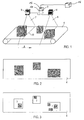
- Fig. 1 shows three objects 1, 2, 3, which are located on a conveyor belt 4, which transports the objects 1, 2, 3 in the direction of the arrow A. Above the conveyor belt 4, a laser scanner 5 and a line camera 6 are successively mounted in the conveying direction A.
- the laser scanner 5 is a line scanner which is suitable for emitting periodically a laser beam moved within a scanning plane 7.
- the scanning plane 7 extends perpendicular to the conveying direction A.
- the laser scanner 5 is positioned relative to the conveyor belt 4 so that the emitted laser beam scans the conveyor belt 4 over a little more than its entire width, so that all objects that are on the conveyor belt 4 , can be detected by the laser scanner 5.
- the V-shaped field of view of the line scan camera 6 lying within a plane 8 is aligned such that all objects conveyed on the conveyor belt 4 under the line scan camera 6 can be detected by the line scan camera 6.
- the plane 8 of the field of view of the line camera 6 extends parallel to the scanning plane 7 of the laser scanner 5 and perpendicular to the conveying direction A.
- Laser scanner 5 and line camera 6 are connected to a control and evaluation circuit 9, which is suitable for one to control laser scanner 5 and line camera 6 in the manner required according to the invention and on the other hand also provides for an evaluation of the data supplied by laser scanner 5 and line scan camera 6 data ,
- the control and evaluation circuit 9 the distances of the laser scanner 5 to the conveying plane of the conveyor belt 4 with respect to all those points are known in which the scanning plane 7 of the laser scanner 5 intersects this conveying plane.
- the corresponding section line is indicated in FIG. 1 by the reference numeral 10.
- the laser scanner 5 delivers distance data which deviates from the known distance data between the laser scanner 5 and the conveying plane, object surfaces which do not coincide with the conveying plane, but which are closer to the laser scanner 5, exist at the positions where the deviations occur the funding level. These positions are then assigned by the control and evaluation circuit 9 of an ROI.
- the evaluation circuit 9 is equipped with a data interface 15, via which data related to ROIs can be transmitted to an external device 16.
- the external device 16 may be suitable, for example, for the automated decoding of characters.
- the evaluation circuit 9 is also equipped with a compression stage 17 which is suitable for compressing the data related to ROIs, in particular already during their detection, so that they can then be transmitted via the data interface 15 to the external device 16 with reduced scope.
- the resolution or the magnification factor of the images captured by the line camera 6 is calculated from the distances supplied by the laser scanner 5, so that it is known, for example with further processing of the ROIs, with which dpi resolution the images captured by the line scan camera 6 are present. This then results in the already explained advantages.
- FIG. 2 shows in plan view the objects 1, 2, 3 transported on the conveyor belt 4.
- the object surfaces visible in plan view, which are shown in gray in FIG. 2, are classified as ROIs by a device according to FIG. 1, so that the Control and evaluation 9 processed only supplied by the line camera 6 image data associated with these ROIs.
- the laser scanner 5 can additionally also be designed to determine the remission behavior of the object surfaces be able to determine in this way, for example, the positions of attached to the object surfaces codes.
- FIG. 3 shows a representation corresponding to FIG. 2, but here only those areas of particular interest are shown as gray-marked ROIs, in which codes to be read by the line scan camera 6 according to FIG. 1 are present.
- the control and evaluation unit 9 it is not necessary to take into account the entire object surfaces apparent from FIG. 2 during image processing by the control and evaluation unit 9. Instead, an evaluation of the areas of the object surfaces indicated in gray in FIG. 3 is sufficient.
- FIG. 4 shows a side view of a line camera 6, which is aligned so that it is suitable for detecting an object 11 which is triangular in cross section.
- the depth of field of the line camera 6 is indicated at 12. It can be seen from FIG. 4 that only a small area 13 of the object 11 facing the line camera 6 is located in the depth of field 12 of the line scan camera 6. In the context of image processing, it therefore makes sense to process only those image data taken by the object 11 which originate from an object surface area which is located within the depth of field 12.
- the distance between the line camera and the surfaces of the object 11 facing it can be determined beforehand, so that ultimately only those image data are processed in the control and evaluation circuit 9 which are assigned to the object surface areas which are located in the depth of field range 12 , In this way, the image data to be processed can be further reduced, which is illustrated in FIGS. 5a and 5b.
- Fig. 5a shows in dark gray color all surface areas of the object 11, which can be detected by the line scan camera 6 of FIG. 4, and regardless of whether they are within the depth of field 12 or not.
- FIG. 5b only those surface areas which can be assigned to the depth of field 12 are shown in dark gray. All other surface areas of the object 11 are shown in light gray color. According to the preferred method according to the invention according to FIG. 4, only those image data reach the further processing by the control and evaluation circuit 9, which are marked dark gray in FIG. 5b and which originate from object surface areas which are located within the depth of field 12 of the line scan camera 6. Thus, depending on the depth of field 12 of the line camera 6, a further reduction of the ROIs defined by the laser scanner 5 is possible.
- Fig. 6 again shows the conveyor belt according to FIGS. 1 to 4, wherein in addition to the objects 1, 2, 3 in top view dark gray hatched also that area 14 is characterized, which can be specifically illuminated by means of an object lighting device, not shown.
- a lighting device can be controlled in such a way that essentially only the ROIs or areas that go beyond the ROIs are illuminated.
- the illumination area 14 according to FIG. 6 is not illuminated at the same time. Rather, it is sufficient to illuminate substantially strip-shaped only that area of the objects 1, 2, 3 which is located within the field of view plane 8 of the line scan camera 6 according to FIG.
- the length and the position of the transversely to the conveying direction A extending strip-shaped area are dependent on the determined via laser scanner 5 and control and evaluation circuit 9 ROIs.
- Fig. 7 shows analogous to Fig. 1 three objects 1, 2, 3, which are transported on a conveyor belt 4 in the direction of arrow A. Above the conveyor belt 4, a laser scanner 5 and a total of three line scan cameras 6, 6 ', 6 "are successively mounted in the conveying direction A.
- the optical axes of the three line scan cameras 6, 6 ', 6 are perpendicular to each other, with the optical axis of the line camera 6 perpendicular to the plane of the conveyor belt 4 and the optical axes of the line scan cameras 6' and 6" extending parallel to said plane. All optical axes of the line scan cameras 6, 6 ', 6 "run perpendicular to the conveying direction A.
- the line scan camera 6 looks from above and the line scan cameras 6', 6" from opposite sides onto the objects 1, 2, 3.
- the control and evaluation circuit 9 is in turn connected to an external device 16, to which the data related to ROIs can be transmitted the operation of the device according to FIG. 7 of the operation of the device shown in Fig. 1, with the only difference that shown in FIG. 7, the data supplied by three line scan cameras 6, 6 ', 6 "for the purpose of further processing stand.
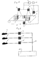
- FIG 8 shows a schematic representation of a network which has a total of three network branches, in each of which an optical sensor 6, 6 ', 6 "and an evaluation circuit 9, 9', 9" assigned to it are arranged.
- the outputs of the evaluation circuits 9, 9 ', 9 " are routed to a common network node 18, which is connected to a further processing station or an external device 16.
- the external device is preferably a host computer which receives the information from the evaluation circuits 9 , 9 ', 9 "supplied data processed.
- the evaluation circuits 9, 9 ', 9 " are designed according to FIG. 8 such that they are also suitable for the optical presentation of the data supplied by the optical sensors 6, 6', 6". Furthermore, they each have an input medium, via which manually recognized by an operator data in the evaluation circuit 9, 9 ', 9 "can be entered.
- FIG. 9 essentially corresponds to FIG. 8 with the difference that the network here does not consist of three network branches, but rather is of star-shaped construction.
- a control computer 19 is also provided, which is designed for the coordination of the data flows and possibly also for the intermediate storage of data.
- An advantage of an arrangement according to FIG. 9 is the fact that all the components 6, 6 ', 6 “, 9, 9', 9", 19 and 16 can communicate with one another within the network. As a result, the advantages already explained above are achieved. In particular, it becomes possible to display on the display unit of any evaluation circuit 9, 9 ', 9 "the data acquired by any of the optical sensors 6, 6', 6".
Landscapes
- Physics & Mathematics (AREA)
- General Physics & Mathematics (AREA)
- Length Measuring Devices By Optical Means (AREA)
- Geophysics And Detection Of Objects (AREA)
- Investigating Materials By The Use Of Optical Means Adapted For Particular Applications (AREA)
- Radar Systems Or Details Thereof (AREA)
Priority Applications (7)
| Application Number | Priority Date | Filing Date | Title |
|---|---|---|---|
| PL05020110T PL1645839T3 (pl) | 2004-10-11 | 2005-09-15 | Urządzenie i sposób kontroli przemieszczanych obiektów |
| DE502005001232T DE502005001232D1 (de) | 2004-10-11 | 2005-09-15 | Vorrichtung und Verfahren zur Überwachung von bewegten Objekten |
| DK05020110T DK1645839T3 (da) | 2004-10-11 | 2005-09-15 | Anordning og metode til registrering af bevægelige objekter |
| ES05020110T ES2289633T3 (es) | 2004-10-11 | 2005-09-15 | Dispositivo y procedimiento para la vigilancia de objetos en movimiento. |
| EP05020110A EP1645839B1 (fr) | 2004-10-11 | 2005-09-15 | Dispositif et procédé pour surveiller des objets en motion |
| AT05020110T ATE370387T1 (de) | 2004-10-11 | 2005-09-15 | Vorrichtung und verfahren zur überwachung von bewegten objekten |
| US11/248,121 US7721964B2 (en) | 2004-10-11 | 2005-10-11 | Apparatus and method for monitoring moved objects |
Applications Claiming Priority (3)
| Application Number | Priority Date | Filing Date | Title |
|---|---|---|---|
| DE102004049482A DE102004049482A1 (de) | 2004-10-11 | 2004-10-11 | Vorrichtung zur Überwachung von bewegten Objekten |
| EP05010273A EP1645838B1 (fr) | 2004-10-11 | 2005-05-11 | Dispositif et procédé pour surveiller des objets en motion |
| EP05020110A EP1645839B1 (fr) | 2004-10-11 | 2005-09-15 | Dispositif et procédé pour surveiller des objets en motion |
Publications (2)
| Publication Number | Publication Date |
|---|---|
| EP1645839A1 true EP1645839A1 (fr) | 2006-04-12 |
| EP1645839B1 EP1645839B1 (fr) | 2007-08-15 |
Family
ID=35149683
Family Applications (1)
| Application Number | Title | Priority Date | Filing Date |
|---|---|---|---|
| EP05020110A Active EP1645839B1 (fr) | 2004-10-11 | 2005-09-15 | Dispositif et procédé pour surveiller des objets en motion |
Country Status (7)
| Country | Link |
|---|---|
| US (1) | US7721964B2 (fr) |
| EP (1) | EP1645839B1 (fr) |
| AT (1) | ATE370387T1 (fr) |
| DE (1) | DE502005001232D1 (fr) |
| DK (1) | DK1645839T3 (fr) |
| ES (1) | ES2289633T3 (fr) |
| PL (1) | PL1645839T3 (fr) |
Cited By (3)
| Publication number | Priority date | Publication date | Assignee | Title |
|---|---|---|---|---|
| US8503027B2 (en) | 2009-03-25 | 2013-08-06 | Heidelberger Druckmaschinen Ag | Method for angle-dependent color value correction |
| US9191567B2 (en) | 2012-07-31 | 2015-11-17 | Sick Ag | Camera system and method of detecting a stream of objects |
| EP3812953A1 (fr) * | 2019-10-22 | 2021-04-28 | Sick Ag | Lecteur de codes et procédé de lecture des codes optiques |
Families Citing this family (22)
| Publication number | Priority date | Publication date | Assignee | Title |
|---|---|---|---|---|
| EP2026249B1 (fr) * | 2007-08-10 | 2010-02-10 | Sick Ag | Réception d'images corrigées d'objets déplacés à l'aide d'une dissolution régulière à l'aide d'un capteur horizontal |
| DE102007048679A1 (de) * | 2007-10-10 | 2009-04-16 | Sick Ag | Vorrichtung und Verfahren zum Aufnehmen von Bildern von auf einer Fördereinrichtung bewegten Objekten |
| US9104935B1 (en) | 2010-12-30 | 2015-08-11 | Cognex Corporation | Mark reader configured to prioritize images |
| IT1404187B1 (it) * | 2011-02-28 | 2013-11-15 | Datalogic Automation Srl | Metodo per l'identificazione ottica di oggetti in movimento |
| US20120327218A1 (en) * | 2011-06-21 | 2012-12-27 | Microsoft Corporation | Resource conservation based on a region of interest |
| US9367725B2 (en) | 2011-11-03 | 2016-06-14 | Cognex Corporation | Method and apparatus for performing different decoding algorithms in different locations |
| US8740081B2 (en) * | 2011-11-03 | 2014-06-03 | Cognex Corporation | Method and apparatus for ordering code candidates in image for decoding attempts |
| EP2693364B1 (fr) | 2012-07-31 | 2014-12-17 | Sick Ag | Système de caméra et procédé de détermination d'un flux d'objets |
| EP2693362B1 (fr) * | 2012-07-31 | 2015-06-17 | Sick Ag | Système de détection destiné à être monté sur une bande de transport |
| CN104955587B (zh) * | 2012-11-21 | 2018-09-18 | 英特里格拉特德总部有限公司 | 用于分选的动态卸料补偿的方法、材料处理系统以及控制器 |
| US9305231B2 (en) | 2013-08-01 | 2016-04-05 | Cognex Corporation | Associating a code with an object |
| KR102273027B1 (ko) * | 2014-06-09 | 2021-07-05 | 삼성전자주식회사 | 위치정보를 사용하여 설정된 관심영역을 사용하여 영상데이터를 생성하는 방법 및 장치 |
| EP3574647B1 (fr) * | 2017-01-25 | 2022-10-26 | Carrier Corporation | Système imageur et de détection en matrice ligne |
| ES2745066T3 (es) | 2017-09-06 | 2020-02-27 | Sick Ag | Dispositivo de cámara y método para grabar un flujo de objetos |
| US10809357B2 (en) | 2017-10-03 | 2020-10-20 | Datalogic Usa, Inc. | Determining object attributes using photoelectric sensors |
| DE102017128331A1 (de) * | 2017-11-29 | 2019-05-29 | Ioss Intelligente Optische Sensoren & Systeme Gmbh | Bildaufnehmersystem |
| EP3663963B1 (fr) | 2018-12-04 | 2021-03-10 | Sick Ag | Lecture de codes optiques |
| US10846551B2 (en) * | 2019-02-06 | 2020-11-24 | Apical Limited | Video data processing |
| DK3708265T3 (da) * | 2019-03-11 | 2021-07-12 | Sick Ag | Sorteringsdetektionssystem til detektion af et objekt, der passerer gennem én af en flerhed af åbninger |
| DE102020112430B4 (de) * | 2020-05-07 | 2021-12-23 | Sick Ag | Kamera und Verfahren zur Erfassung von Objekten |
| DE102020113183B4 (de) * | 2020-05-15 | 2021-12-16 | Sick Ag | Kamera und Verfahren zur Erfassung von bewegten Objekten |
| DE102021109078B3 (de) | 2021-04-12 | 2022-11-03 | Sick Ag | Kameravorrichtung und Verfahren zur Erfassung eines bewegten Stromes von Objekten |
Citations (6)
| Publication number | Priority date | Publication date | Assignee | Title |
|---|---|---|---|---|
| US5311999A (en) * | 1989-12-23 | 1994-05-17 | Licentia Patent-Verwaltungs-Gmbh | Method of distributing packages or the like |
| JPH10210354A (ja) * | 1997-01-27 | 1998-08-07 | Minolta Co Ltd | デジタルカメラ |
| US5912698A (en) * | 1995-09-05 | 1999-06-15 | International Business Machines Corporation | Image recording system |
| EP0984382A2 (fr) * | 1998-09-04 | 2000-03-08 | Sick AG | Methode d'utilisation d'un lecteur de code à barres |
| WO2002007904A1 (fr) * | 2000-07-25 | 2002-01-31 | Solystic | Procede de traitement d'objets postaux de grande taille dans une installation de tri |
| EP1431707A1 (fr) * | 2002-12-20 | 2004-06-23 | Sick AG | Procédé et dispositif pour l'acquisition, au moyen d'un capteur optoélectronique, d'objets placés sur un convoyeur |
Family Cites Families (16)
| Publication number | Priority date | Publication date | Assignee | Title |
|---|---|---|---|---|
| IL107265A0 (en) | 1993-10-12 | 1994-01-25 | Galai Lab Ltd | Parcel sorting system |
| FR2746330B1 (fr) * | 1996-03-22 | 1998-04-17 | Alcatel Postal Automation Syst | Systeme d'acquisition d'images pour le tri de paquets |
| DE19639854A1 (de) | 1996-09-27 | 1998-06-10 | Vitronic Dr Ing Stein Bildvera | Verfahren und Vorrichtung zur Erfassung von auf potentiell großflächigen Gegenständen aufgebrachten, optisch erfaßbaren Informationen |
| DE19727459A1 (de) | 1997-06-27 | 1999-01-07 | Sick Ag | Opto-elektronische Sensoranordnung mit mehreren in einer Zeile oder einem Array angeordneten photoempfindlichen Elementen |
| DE19946476A1 (de) | 1999-09-28 | 2001-03-29 | Sick Ag | Verfahren und Vorrichtung zum Überwachen eines Schutzbereichs |
| US6603563B1 (en) | 2000-04-05 | 2003-08-05 | Accu-Sort Systems, Inc. | Apparatus for determining measurements of an object utilizing negative imaging |
| DE10113641B4 (de) | 2001-03-21 | 2005-05-19 | Leuze Electronic Gmbh & Co Kg | Optoelektronische Vorrichtung |
| DE10126086A1 (de) | 2001-05-29 | 2002-12-05 | Sick Ag | Optoelektronischer Sensor |
| DE10148062A1 (de) | 2001-09-28 | 2003-04-10 | Ibeo Automobile Sensor Gmbh | Verfahren zur Verarbeitung eines tiefenaufgelösten Bildes |
| DE10154861A1 (de) | 2001-11-08 | 2003-05-22 | Ibeo Automobile Sensor Gmbh | Verfahren zur Bereitstellung von Bildinformationen |
| KR100456628B1 (ko) * | 2001-12-28 | 2004-11-10 | 한국전자통신연구원 | 물류 정보 자동식별 처리시스템 및 그 방법 |
| JP4251312B2 (ja) | 2002-03-08 | 2009-04-08 | 日本電気株式会社 | 画像入力装置 |
| DE10229408B4 (de) | 2002-06-29 | 2006-09-07 | Leuze Electronic Gmbh & Co Kg | Optischer Sensor |
| DE10231178B4 (de) | 2002-07-10 | 2008-12-04 | Sick Ag | Optoelektronischer Sensor |
| DE10304054B4 (de) | 2003-02-01 | 2005-03-03 | Leuze Lumiflex Gmbh + Co. Kg | Optischer Sensor |
| DE102004008925B4 (de) | 2003-02-28 | 2006-04-13 | Leuze Electronic Gmbh & Co Kg | Optoelektronische Vorrichtung |
-
2005
- 2005-09-15 DE DE502005001232T patent/DE502005001232D1/de active Active
- 2005-09-15 AT AT05020110T patent/ATE370387T1/de active
- 2005-09-15 PL PL05020110T patent/PL1645839T3/pl unknown
- 2005-09-15 DK DK05020110T patent/DK1645839T3/da active
- 2005-09-15 EP EP05020110A patent/EP1645839B1/fr active Active
- 2005-09-15 ES ES05020110T patent/ES2289633T3/es active Active
- 2005-10-11 US US11/248,121 patent/US7721964B2/en active Active
Patent Citations (6)
| Publication number | Priority date | Publication date | Assignee | Title |
|---|---|---|---|---|
| US5311999A (en) * | 1989-12-23 | 1994-05-17 | Licentia Patent-Verwaltungs-Gmbh | Method of distributing packages or the like |
| US5912698A (en) * | 1995-09-05 | 1999-06-15 | International Business Machines Corporation | Image recording system |
| JPH10210354A (ja) * | 1997-01-27 | 1998-08-07 | Minolta Co Ltd | デジタルカメラ |
| EP0984382A2 (fr) * | 1998-09-04 | 2000-03-08 | Sick AG | Methode d'utilisation d'un lecteur de code à barres |
| WO2002007904A1 (fr) * | 2000-07-25 | 2002-01-31 | Solystic | Procede de traitement d'objets postaux de grande taille dans une installation de tri |
| EP1431707A1 (fr) * | 2002-12-20 | 2004-06-23 | Sick AG | Procédé et dispositif pour l'acquisition, au moyen d'un capteur optoélectronique, d'objets placés sur un convoyeur |
Non-Patent Citations (1)
| Title |
|---|
| PATENT ABSTRACTS OF JAPAN vol. 1998, no. 13 30 November 1998 (1998-11-30) * |
Cited By (4)
| Publication number | Priority date | Publication date | Assignee | Title |
|---|---|---|---|---|
| US8503027B2 (en) | 2009-03-25 | 2013-08-06 | Heidelberger Druckmaschinen Ag | Method for angle-dependent color value correction |
| US9191567B2 (en) | 2012-07-31 | 2015-11-17 | Sick Ag | Camera system and method of detecting a stream of objects |
| EP3812953A1 (fr) * | 2019-10-22 | 2021-04-28 | Sick Ag | Lecteur de codes et procédé de lecture des codes optiques |
| US11170191B2 (en) | 2019-10-22 | 2021-11-09 | Sick Ag | Code reader and method for reading of optical codes |
Also Published As
| Publication number | Publication date |
|---|---|
| ES2289633T3 (es) | 2008-02-01 |
| US20060076415A1 (en) | 2006-04-13 |
| ATE370387T1 (de) | 2007-09-15 |
| DE502005001232D1 (de) | 2007-09-27 |
| DK1645839T3 (da) | 2007-10-29 |
| PL1645839T3 (pl) | 2007-12-31 |
| EP1645839B1 (fr) | 2007-08-15 |
| US7721964B2 (en) | 2010-05-25 |
Similar Documents
| Publication | Publication Date | Title |
|---|---|---|
| EP1645839B1 (fr) | Dispositif et procédé pour surveiller des objets en motion | |
| EP1645838B1 (fr) | Dispositif et procédé pour surveiller des objets en motion | |
| EP3454298B1 (fr) | Système de caméra et procédé de détermination d'un flux d'objets | |
| EP2693364B1 (fr) | Système de caméra et procédé de détermination d'un flux d'objets | |
| EP3275313A1 (fr) | Dispositif de détection et d'évaluation d'informations spécifiques à des produits provenant de l'industrie agroalimentaire et système comprenant un tel dispositif et procédé de traitement de produits provenant de l'industrie agroalimentaire | |
| EP2555160B1 (fr) | Production d'une image présegmentée en domaines intéressants et inintéressants | |
| DE112013000571B4 (de) | Verfahren zum Decodieren eines Strichcodes innerhalb eines Bilderzeugungssichtfelds eines Bilderzeugungssystems und Vorrichtung | |
| DE202006020599U1 (de) | Optische Erfassung von bewegten Objekten und Vorrichtung | |
| EP2003599A1 (fr) | Capteur optoélectronique et procédé destiné à la saisie de codes | |
| DE102017215334A1 (de) | Verfahren, Computerprogrammprodukt und Messsystem zum Betrieb mindestens eines Triangulations-Laserscanners zur Identifizierung von Oberflächeneigenschaften eines zu vermessenden Werkstücks | |
| EP3789906B1 (fr) | Déterminer la taille du module d'un code optique | |
| EP3663963A1 (fr) | Lecture de codes optiques | |
| DE69921021T2 (de) | Verfahren zum Unterscheiden von Produkteinheiten und Vorrichtung dazu | |
| DE102017106831A1 (de) | Kamera und Verfahren zur Erfassung von relativ zu der Kamera in einer Förderrichtung bewegten Objekten | |
| DE102019100821A1 (de) | Boroskop zur optischen Inspektion von Gasturbinen | |
| EP2677492A1 (fr) | Lecteur de code et procédé de vérification en ligne d'un code | |
| EP1365577B1 (fr) | Procédé de fonctionnement d'un capteur opto-électronique | |
| DE102017128032A1 (de) | Codelesevorrichtung und Verfahren zur Online-Verifikation eines Codes | |
| WO2019185184A1 (fr) | Dispositif et procédé pour la détection optique de position d'objets transportés | |
| EP1139285B1 (fr) | Procédé et dispositif pour contrôle ou inspection d'objets | |
| DE20317095U1 (de) | Vorrichtung zur Erkennung von Oberflächenfehlern | |
| DE202014101714U1 (de) | Codelesesystem zum Lesen von Codes | |
| DE4200801A1 (de) | Vorrichtung zur durchfuehrung einer qualitaetskontrolle | |
| EP1357506A2 (fr) | Procédé d'utilisation d'un capteur optique, notamment d'un lecteur de code et lecteur de code | |
| EP0789832A1 (fr) | Procede et dispositif de verification optique de produits |
Legal Events
| Date | Code | Title | Description |
|---|---|---|---|
| PUAI | Public reference made under article 153(3) epc to a published international application that has entered the european phase |
Free format text: ORIGINAL CODE: 0009012 |
|
| AK | Designated contracting states |
Kind code of ref document: A1 Designated state(s): AT BE BG CH CY CZ DE DK EE ES FI FR GB GR HU IE IS IT LI LT LU LV MC NL PL PT RO SE SI SK TR |
|
| AX | Request for extension of the european patent |
Extension state: AL BA HR MK YU |
|
| 17P | Request for examination filed |
Effective date: 20060726 |
|
| 17Q | First examination report despatched |
Effective date: 20061114 |
|
| AKX | Designation fees paid |
Designated state(s): AT BE BG CH CY CZ DE DK EE ES FI FR GB GR HU IE IS IT LI LT LU LV MC NL PL PT RO SE SI SK TR |
|
| RAP1 | Party data changed (applicant data changed or rights of an application transferred) |
Owner name: SICK AG |
|
| GRAP | Despatch of communication of intention to grant a patent |
Free format text: ORIGINAL CODE: EPIDOSNIGR1 |
|
| GRAS | Grant fee paid |
Free format text: ORIGINAL CODE: EPIDOSNIGR3 |
|
| GRAA | (expected) grant |
Free format text: ORIGINAL CODE: 0009210 |
|
| AK | Designated contracting states |
Kind code of ref document: B1 Designated state(s): AT BE BG CH CY CZ DE DK EE ES FI FR GB GR HU IE IS IT LI LT LU LV MC NL PL PT RO SE SI SK TR |
|
| REG | Reference to a national code |
Ref country code: GB Ref legal event code: FG4D Free format text: NOT ENGLISH |
|
| REG | Reference to a national code |
Ref country code: CH Ref legal event code: EP |
|
| REG | Reference to a national code |
Ref country code: IE Ref legal event code: FG4D Free format text: LANGUAGE OF EP DOCUMENT: GERMAN |
|
| REF | Corresponds to: |
Ref document number: 502005001232 Country of ref document: DE Date of ref document: 20070927 Kind code of ref document: P |
|
| GBT | Gb: translation of ep patent filed (gb section 77(6)(a)/1977) |
Effective date: 20071001 |
|
| REG | Reference to a national code |
Ref country code: DK Ref legal event code: T3 |
|
| REG | Reference to a national code |
Ref country code: PT Ref legal event code: SC4A Free format text: AVAILABILITY OF NATIONAL TRANSLATION Effective date: 20071105 |
|
| REG | Reference to a national code |
Ref country code: SE Ref legal event code: TRGR |
|
| REG | Reference to a national code |
Ref country code: PL Ref legal event code: T3 |
|
| PG25 | Lapsed in a contracting state [announced via postgrant information from national office to epo] |
Ref country code: LT Free format text: LAPSE BECAUSE OF FAILURE TO SUBMIT A TRANSLATION OF THE DESCRIPTION OR TO PAY THE FEE WITHIN THE PRESCRIBED TIME-LIMIT Effective date: 20070815 Ref country code: IS Free format text: LAPSE BECAUSE OF FAILURE TO SUBMIT A TRANSLATION OF THE DESCRIPTION OR TO PAY THE FEE WITHIN THE PRESCRIBED TIME-LIMIT Effective date: 20071215 Ref country code: BG Free format text: LAPSE BECAUSE OF FAILURE TO SUBMIT A TRANSLATION OF THE DESCRIPTION OR TO PAY THE FEE WITHIN THE PRESCRIBED TIME-LIMIT Effective date: 20071115 |
|
| REG | Reference to a national code |
Ref country code: ES Ref legal event code: FG2A Ref document number: 2289633 Country of ref document: ES Kind code of ref document: T3 |
|
| ET | Fr: translation filed | ||
| PG25 | Lapsed in a contracting state [announced via postgrant information from national office to epo] |
Ref country code: LV Free format text: LAPSE BECAUSE OF FAILURE TO SUBMIT A TRANSLATION OF THE DESCRIPTION OR TO PAY THE FEE WITHIN THE PRESCRIBED TIME-LIMIT Effective date: 20070815 |
|
| PG25 | Lapsed in a contracting state [announced via postgrant information from national office to epo] |
Ref country code: GR Free format text: LAPSE BECAUSE OF FAILURE TO SUBMIT A TRANSLATION OF THE DESCRIPTION OR TO PAY THE FEE WITHIN THE PRESCRIBED TIME-LIMIT Effective date: 20071116 Ref country code: MC Free format text: LAPSE BECAUSE OF NON-PAYMENT OF DUE FEES Effective date: 20070930 |
|
| PG25 | Lapsed in a contracting state [announced via postgrant information from national office to epo] |
Ref country code: CZ Free format text: LAPSE BECAUSE OF FAILURE TO SUBMIT A TRANSLATION OF THE DESCRIPTION OR TO PAY THE FEE WITHIN THE PRESCRIBED TIME-LIMIT Effective date: 20070815 Ref country code: SK Free format text: LAPSE BECAUSE OF FAILURE TO SUBMIT A TRANSLATION OF THE DESCRIPTION OR TO PAY THE FEE WITHIN THE PRESCRIBED TIME-LIMIT Effective date: 20070815 |
|
| PLBE | No opposition filed within time limit |
Free format text: ORIGINAL CODE: 0009261 |
|
| STAA | Information on the status of an ep patent application or granted ep patent |
Free format text: STATUS: NO OPPOSITION FILED WITHIN TIME LIMIT |
|
| PG25 | Lapsed in a contracting state [announced via postgrant information from national office to epo] |
Ref country code: RO Free format text: LAPSE BECAUSE OF FAILURE TO SUBMIT A TRANSLATION OF THE DESCRIPTION OR TO PAY THE FEE WITHIN THE PRESCRIBED TIME-LIMIT Effective date: 20070815 |
|
| 26N | No opposition filed |
Effective date: 20080516 |
|
| PG25 | Lapsed in a contracting state [announced via postgrant information from national office to epo] |
Ref country code: EE Free format text: LAPSE BECAUSE OF FAILURE TO SUBMIT A TRANSLATION OF THE DESCRIPTION OR TO PAY THE FEE WITHIN THE PRESCRIBED TIME-LIMIT Effective date: 20070815 |
|
| PG25 | Lapsed in a contracting state [announced via postgrant information from national office to epo] |
Ref country code: SI Free format text: LAPSE BECAUSE OF FAILURE TO SUBMIT A TRANSLATION OF THE DESCRIPTION OR TO PAY THE FEE WITHIN THE PRESCRIBED TIME-LIMIT Effective date: 20070815 |
|
| PG25 | Lapsed in a contracting state [announced via postgrant information from national office to epo] |
Ref country code: CY Free format text: LAPSE BECAUSE OF FAILURE TO SUBMIT A TRANSLATION OF THE DESCRIPTION OR TO PAY THE FEE WITHIN THE PRESCRIBED TIME-LIMIT Effective date: 20070815 |
|
| PG25 | Lapsed in a contracting state [announced via postgrant information from national office to epo] |
Ref country code: LU Free format text: LAPSE BECAUSE OF NON-PAYMENT OF DUE FEES Effective date: 20070915 |
|
| PG25 | Lapsed in a contracting state [announced via postgrant information from national office to epo] |
Ref country code: TR Free format text: LAPSE BECAUSE OF FAILURE TO SUBMIT A TRANSLATION OF THE DESCRIPTION OR TO PAY THE FEE WITHIN THE PRESCRIBED TIME-LIMIT Effective date: 20070815 Ref country code: HU Free format text: LAPSE BECAUSE OF FAILURE TO SUBMIT A TRANSLATION OF THE DESCRIPTION OR TO PAY THE FEE WITHIN THE PRESCRIBED TIME-LIMIT Effective date: 20080216 |
|
| PGFP | Annual fee paid to national office [announced via postgrant information from national office to epo] |
Ref country code: PL Payment date: 20100906 Year of fee payment: 6 |
|
| PGFP | Annual fee paid to national office [announced via postgrant information from national office to epo] |
Ref country code: PT Payment date: 20100906 Year of fee payment: 6 |
|
| REG | Reference to a national code |
Ref country code: PT Ref legal event code: MM4A Free format text: LAPSE DUE TO NON-PAYMENT OF FEES Effective date: 20120315 |
|
| PG25 | Lapsed in a contracting state [announced via postgrant information from national office to epo] |
Ref country code: PT Free format text: LAPSE BECAUSE OF NON-PAYMENT OF DUE FEES Effective date: 20120315 |
|
| PG25 | Lapsed in a contracting state [announced via postgrant information from national office to epo] |
Ref country code: PL Free format text: LAPSE BECAUSE OF NON-PAYMENT OF DUE FEES Effective date: 20110915 |
|
| REG | Reference to a national code |
Ref country code: PL Ref legal event code: LAPE |
|
| PGFP | Annual fee paid to national office [announced via postgrant information from national office to epo] |
Ref country code: AT Payment date: 20130919 Year of fee payment: 9 Ref country code: IE Payment date: 20130919 Year of fee payment: 9 Ref country code: ES Payment date: 20130923 Year of fee payment: 9 Ref country code: FI Payment date: 20130919 Year of fee payment: 9 Ref country code: SE Payment date: 20130920 Year of fee payment: 9 |
|
| PGFP | Annual fee paid to national office [announced via postgrant information from national office to epo] |
Ref country code: BE Payment date: 20130919 Year of fee payment: 9 |
|
| PGFP | Annual fee paid to national office [announced via postgrant information from national office to epo] |
Ref country code: CH Payment date: 20140922 Year of fee payment: 10 |
|
| PG25 | Lapsed in a contracting state [announced via postgrant information from national office to epo] |
Ref country code: FI Free format text: LAPSE BECAUSE OF NON-PAYMENT OF DUE FEES Effective date: 20140915 |
|
| REG | Reference to a national code |
Ref country code: SE Ref legal event code: EUG |
|
| REG | Reference to a national code |
Ref country code: AT Ref legal event code: MM01 Ref document number: 370387 Country of ref document: AT Kind code of ref document: T Effective date: 20140915 |
|
| PG25 | Lapsed in a contracting state [announced via postgrant information from national office to epo] |
Ref country code: SE Free format text: LAPSE BECAUSE OF NON-PAYMENT OF DUE FEES Effective date: 20140916 |
|
| REG | Reference to a national code |
Ref country code: IE Ref legal event code: MM4A |
|
| PG25 | Lapsed in a contracting state [announced via postgrant information from national office to epo] |
Ref country code: BE Free format text: LAPSE BECAUSE OF NON-PAYMENT OF DUE FEES Effective date: 20140930 |
|
| PG25 | Lapsed in a contracting state [announced via postgrant information from national office to epo] |
Ref country code: AT Free format text: LAPSE BECAUSE OF NON-PAYMENT OF DUE FEES Effective date: 20140915 Ref country code: IE Free format text: LAPSE BECAUSE OF NON-PAYMENT OF DUE FEES Effective date: 20140915 |
|
| REG | Reference to a national code |
Ref country code: FR Ref legal event code: PLFP Year of fee payment: 11 |
|
| REG | Reference to a national code |
Ref country code: ES Ref legal event code: FD2A Effective date: 20151027 |
|
| PGFP | Annual fee paid to national office [announced via postgrant information from national office to epo] |
Ref country code: GB Payment date: 20150922 Year of fee payment: 11 |
|
| PGFP | Annual fee paid to national office [announced via postgrant information from national office to epo] |
Ref country code: FR Payment date: 20150923 Year of fee payment: 11 |
|
| PGFP | Annual fee paid to national office [announced via postgrant information from national office to epo] |
Ref country code: DK Payment date: 20150923 Year of fee payment: 11 |
|
| PG25 | Lapsed in a contracting state [announced via postgrant information from national office to epo] |
Ref country code: ES Free format text: LAPSE BECAUSE OF NON-PAYMENT OF DUE FEES Effective date: 20140916 |
|
| PGFP | Annual fee paid to national office [announced via postgrant information from national office to epo] |
Ref country code: NL Payment date: 20150923 Year of fee payment: 11 |
|
| REG | Reference to a national code |
Ref country code: CH Ref legal event code: PL |
|
| PG25 | Lapsed in a contracting state [announced via postgrant information from national office to epo] |
Ref country code: LI Free format text: LAPSE BECAUSE OF NON-PAYMENT OF DUE FEES Effective date: 20150930 Ref country code: CH Free format text: LAPSE BECAUSE OF NON-PAYMENT OF DUE FEES Effective date: 20150930 |
|
| REG | Reference to a national code |
Ref country code: DK Ref legal event code: EBP Effective date: 20160930 |
|
| REG | Reference to a national code |
Ref country code: NL Ref legal event code: MM Effective date: 20161001 |
|
| GBPC | Gb: european patent ceased through non-payment of renewal fee |
Effective date: 20160915 |
|
| PG25 | Lapsed in a contracting state [announced via postgrant information from national office to epo] |
Ref country code: NL Free format text: LAPSE BECAUSE OF NON-PAYMENT OF DUE FEES Effective date: 20161001 |
|
| REG | Reference to a national code |
Ref country code: FR Ref legal event code: ST Effective date: 20170531 |
|
| PG25 | Lapsed in a contracting state [announced via postgrant information from national office to epo] |
Ref country code: FR Free format text: LAPSE BECAUSE OF NON-PAYMENT OF DUE FEES Effective date: 20160930 Ref country code: GB Free format text: LAPSE BECAUSE OF NON-PAYMENT OF DUE FEES Effective date: 20160915 |
|
| PG25 | Lapsed in a contracting state [announced via postgrant information from national office to epo] |
Ref country code: DK Free format text: LAPSE BECAUSE OF NON-PAYMENT OF DUE FEES Effective date: 20160930 |
|
| PGFP | Annual fee paid to national office [announced via postgrant information from national office to epo] |
Ref country code: DE Payment date: 20230919 Year of fee payment: 19 |
|
| PGFP | Annual fee paid to national office [announced via postgrant information from national office to epo] |
Ref country code: IT Payment date: 20230929 Year of fee payment: 19 |