EP1645708A2 - Unité d'entraînement avec élément flexible de transmission et ensemble de poulie réglable - Google Patents
Unité d'entraînement avec élément flexible de transmission et ensemble de poulie réglable Download PDFInfo
- Publication number
- EP1645708A2 EP1645708A2 EP05077212A EP05077212A EP1645708A2 EP 1645708 A2 EP1645708 A2 EP 1645708A2 EP 05077212 A EP05077212 A EP 05077212A EP 05077212 A EP05077212 A EP 05077212A EP 1645708 A2 EP1645708 A2 EP 1645708A2
- Authority
- EP
- European Patent Office
- Prior art keywords
- pulley
- guide channel
- axis
- assembly
- axially spaced
- Prior art date
- Legal status (The legal status is an assumption and is not a legal conclusion. Google has not performed a legal analysis and makes no representation as to the accuracy of the status listed.)
- Withdrawn
Links
Images

Classifications
-
- E—FIXED CONSTRUCTIONS
- E05—LOCKS; KEYS; WINDOW OR DOOR FITTINGS; SAFES
- E05F—DEVICES FOR MOVING WINGS INTO OPEN OR CLOSED POSITION; CHECKS FOR WINGS; WING FITTINGS NOT OTHERWISE PROVIDED FOR, CONCERNED WITH THE FUNCTIONING OF THE WING
- E05F15/00—Power-operated mechanisms for wings
- E05F15/60—Power-operated mechanisms for wings using electrical actuators
- E05F15/603—Power-operated mechanisms for wings using electrical actuators using rotary electromotors
- E05F15/611—Power-operated mechanisms for wings using electrical actuators using rotary electromotors for swinging wings
- E05F15/627—Power-operated mechanisms for wings using electrical actuators using rotary electromotors for swinging wings operated by flexible elongated pulling elements, e.g. belts, chains or cables
-
- E—FIXED CONSTRUCTIONS
- E05—LOCKS; KEYS; WINDOW OR DOOR FITTINGS; SAFES
- E05F—DEVICES FOR MOVING WINGS INTO OPEN OR CLOSED POSITION; CHECKS FOR WINGS; WING FITTINGS NOT OTHERWISE PROVIDED FOR, CONCERNED WITH THE FUNCTIONING OF THE WING
- E05F15/00—Power-operated mechanisms for wings
- E05F15/60—Power-operated mechanisms for wings using electrical actuators
- E05F15/603—Power-operated mechanisms for wings using electrical actuators using rotary electromotors
- E05F15/611—Power-operated mechanisms for wings using electrical actuators using rotary electromotors for swinging wings
- E05F15/63—Power-operated mechanisms for wings using electrical actuators using rotary electromotors for swinging wings operated by swinging arms
-
- E—FIXED CONSTRUCTIONS
- E05—LOCKS; KEYS; WINDOW OR DOOR FITTINGS; SAFES
- E05Y—INDEXING SCHEME ASSOCIATED WITH SUBCLASSES E05D AND E05F, RELATING TO CONSTRUCTION ELEMENTS, ELECTRIC CONTROL, POWER SUPPLY, POWER SIGNAL OR TRANSMISSION, USER INTERFACES, MOUNTING OR COUPLING, DETAILS, ACCESSORIES, AUXILIARY OPERATIONS NOT OTHERWISE PROVIDED FOR, APPLICATION THEREOF
- E05Y2201/00—Constructional elements; Accessories therefor
- E05Y2201/20—Brakes; Disengaging means; Holders; Stops; Valves; Accessories therefor
- E05Y2201/214—Disengaging means
- E05Y2201/216—Clutches
-
- E—FIXED CONSTRUCTIONS
- E05—LOCKS; KEYS; WINDOW OR DOOR FITTINGS; SAFES
- E05Y—INDEXING SCHEME ASSOCIATED WITH SUBCLASSES E05D AND E05F, RELATING TO CONSTRUCTION ELEMENTS, ELECTRIC CONTROL, POWER SUPPLY, POWER SIGNAL OR TRANSMISSION, USER INTERFACES, MOUNTING OR COUPLING, DETAILS, ACCESSORIES, AUXILIARY OPERATIONS NOT OTHERWISE PROVIDED FOR, APPLICATION THEREOF
- E05Y2201/00—Constructional elements; Accessories therefor
- E05Y2201/20—Brakes; Disengaging means; Holders; Stops; Valves; Accessories therefor
- E05Y2201/23—Actuation thereof
- E05Y2201/246—Actuation thereof by auxiliary motors, magnets, springs or weights
-
- E—FIXED CONSTRUCTIONS
- E05—LOCKS; KEYS; WINDOW OR DOOR FITTINGS; SAFES
- E05Y—INDEXING SCHEME ASSOCIATED WITH SUBCLASSES E05D AND E05F, RELATING TO CONSTRUCTION ELEMENTS, ELECTRIC CONTROL, POWER SUPPLY, POWER SIGNAL OR TRANSMISSION, USER INTERFACES, MOUNTING OR COUPLING, DETAILS, ACCESSORIES, AUXILIARY OPERATIONS NOT OTHERWISE PROVIDED FOR, APPLICATION THEREOF
- E05Y2201/00—Constructional elements; Accessories therefor
- E05Y2201/40—Motors; Magnets; Springs; Weights; Accessories therefor
- E05Y2201/46—Magnets
- E05Y2201/462—Electromagnets
-
- E—FIXED CONSTRUCTIONS
- E05—LOCKS; KEYS; WINDOW OR DOOR FITTINGS; SAFES
- E05Y—INDEXING SCHEME ASSOCIATED WITH SUBCLASSES E05D AND E05F, RELATING TO CONSTRUCTION ELEMENTS, ELECTRIC CONTROL, POWER SUPPLY, POWER SIGNAL OR TRANSMISSION, USER INTERFACES, MOUNTING OR COUPLING, DETAILS, ACCESSORIES, AUXILIARY OPERATIONS NOT OTHERWISE PROVIDED FOR, APPLICATION THEREOF
- E05Y2900/00—Application of doors, windows, wings or fittings thereof
- E05Y2900/50—Application of doors, windows, wings or fittings thereof for vehicles
- E05Y2900/53—Type of wing
- E05Y2900/546—Tailboards, tailgates or sideboards opening upwards
Definitions
- This invention relates to an adjustable pulley assembly and a drive unit having an endless flexible drive member that is suitable for use in a power operated closure system such as, for example, a power operated lift-gate system in an automotive vehicle.
- U.S. Patent No. 6,367,864 B2 granted to Lloyd Walker Rogers, Jr. et al. April 9, 2004 discloses a vehicle having a power operated lift-gate system that includes at least one drive unit.
- the drive unit comprises a fixed linear guide channel and a follower that moves in the guide channel.
- a rod is universally connected to the follower at one end and universally connected to the lift-gate at the opposite end.
- An endless flexible drive member that is attached to the follower wraps part way around two idler pulleys at the opposite ends of the guide channel and travels in a closed loop.
- the flexible drive member is driven by a bi-directional power unit that includes a drive sprocket.
- the drive sprocket drivingly engages the loop of the flexible drive member outside the drive channel midway between the two idler pulleys.
- this invention provides a drive unit having an endless flexible drive member that is more compact than the drive unit that is disclosed in the Rogers et al. '864 patent.
- this invention provides a compact drive unit that includes an adjustable pulley assembly to take up slack in the flexible drive member.
- this invention provides an adjustable pulley assembly that is unique, compact and economical.
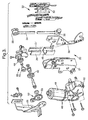
- vehicle 10 has a closure or lift-gate 12 that is attached to the aft end of the vehicle roof by two hinge assemblies 14.
- Hinge assemblies 14 have hinge portions that are secured to a roof channel of the vehicle 10 and hinge portions that are secured to lift-gate 12 so that lift-gate 12 pivots about a substantially horizontal hinge axis 16 between a closed position shown in solid line in figure 1 and an open position shown in dashed lines in figure 1.
- Lift-gate 12 is generally permitted to pivot about 90° about the substantially horizontal hinge axis 16. However, the range of movement can be varied substantially from one model of vehicle to another.
- Lift-gate 12 is opened and closed manually or by a suitable power operated closure system comprising two identical drive units 20 that are installed in the aft end of the vehicle body at the respective vertical body pillars 22, commonly referred to as the D pillars, that define the width of the rear opening that is closed by lift-gate 12.
- the typical drive unit 20 is shown in greater detail in figures 2 through 6.
- Each power unit 20 comprises a fixed rectangular guide channel 24 that is fixed to a body portion of the vehicle in a generally vertical orientation by upper and lower brackets 25 and 26 at or near the D pillar 22.
- the rectangular guide channel 24 has an elongated longitudinal slot 27 in a rearward facing wall 28 of the guide channel 24 that faces toward lift-gate 12 when lift-gate 12 is in the closed position.
- Attachment Assembly 30 is disposed in the guide channel 24 and moves along in the guide channel.
- Attachment Assembly 30 has a universal connector in the form of a ball stud 32 that projects through slot 27.
- a rod 34 has a mating universal connector in the form of a socket 36 at one end that receives the ball stud 32 so that rod 34 is universally connected to assembly 30.
- Rod 34 has a socket 38 at an opposite end that is universally connected to a mating ball stud 40 attached to a side wall of the vehicle lift gate 12.
- any type of universal connector can be used between rod 34 and attachment assembly 30 at one end of rod 34 and between rod 34 and lift-gate 12 at the other end of rod 34 and that the positions of the ball studs and the sockets of the ball joints 32, 36 and 38, 40 of illustrated example can be reversed.
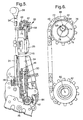
- Drive unit 20 further comprises a first pulley 42 at a lower end of the guide channel 24 and a second pulley 44 at an upper end of the guide channel.
- a flexible drive member in the form of a drive chain 46 extends into the upper and lower open ends of guide channel 24.
- the opposite ends of drive chain 46 are attached to the opposite ends of attachment assembly 30 so that drive chain 46 is in effect, an endless flexible drive member that travels in a loop.
- the drive chain or flexible drive member 46 is trained solely around pulleys 42 and 44.
- drive chain 46 extends up from attachment assembly 30 directly to pulley 44, then wraps substantially 180 degrees around upper pulley 44, then extends directly down to lower pulley 42, then wraps substantially 180 degrees around lower pulley 42 and then extends directly back up to attachment assembly 30 as best shown in figure 5.
- flexible drive member 46 of drive unit 20 is engaged solely by two pulleys, drive pulley 42 and idler pulley 44 to form the flexible drive member 46 in a narrow loop having a width determined by the diameter of pulleys 42 and 44.
- Pulleys 42 and 44 preferably have equal diameters. This contributes to a very compact arrangement for drive unit 20.
- Pulleys 42 and 44 (which are preferably sprockets when a drive chain is used) are aligned with the end wall 45 of rectangular guide channel 24 so that the portions of the drive chain 46 between pulleys 42 and 44 inside as well as outside the guide channel 24 are spaced from the end wall 45.
- Drive unit 20 further comprises a bi-directional power unit 48 that is drivingly connected to the lower pulley 42 so that power unit 20 drives drive chain 46 in one direction to move lift-gate 12 to the open position and in an opposite direction to move lift-gate 12 to the closed position.
- Power unit 48 is drivingly attached to a pulley at one end of the guide channel 24 for efficient packaging.
- Power unit 48 is preferably drivingly attached to the lower pulley 42 to minimize the intrusion into the load area of the vehicle but may be drivingly attached to the upper pulley 44.
- one pulley is a drive pulley while the other pulley is an idler pulley, or in the case of a chain drive unit, one is an idler sprocket while the other is a drive sprocket.
- Bi-directional power unit 48 includes a reversible electric motor 49 and preferably an electromagnetic clutch 50 attached to the lower end of the guide channel 24 by a power unit bracket 51.
- Electromagnetic clutch 50 is driven by reversible electric motor 49 via a suitable gear set and lower pulley (drive sprocket) 42 is driven by electromagnetic clutch 50 through a second suitable gear set 52.
- drive unit 20 includes a pulley 44 at the upper end of guide channel 24 that is an idler pulley or in the case of a chain drive unit, an idler sprocket.
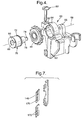
- Pulley 44 is part of an adjustable pulley assembly 60 that includes a housing 62 that is attached to the upper end of guide channel 24 as best shown in figures 2 through 6.
- Housing 62 has a first journal box 64 and a second journal box 66 located on a fixed housing axis 68 that is generally coplanar with or closely parallel to the end wall 45 of the guide channel 24.
- Journal boxes 64 and 66 are spaced axially from each other to provide space for pulley 44.
- Pulley assembly 60 also includes a camshaft 70 having axially spaced concentric bearing portions 72 and 74 that are disposed in the first journal box 64 and the second journal box 64, respectively for rotation about the fixed housing axis 68.
- Camshaft 70 has a cam 76 between the bearing portions 72 and 74.
- Cam 76 is circular having a center that defines an adjustable pulley axis 78 that is substantially parallel to and offset from the fixed housing axis 68 defined by the bearing portions 72 and 74 disposed in the journal boxes 64 and 66.
- Pulley 44 is disposed between journal boxes 64 and 66 and rotationally supported on circular cam 76 for rotation about the adjustable pulley axis 78.
- Cam shaft 70 can be clamped in housing 62 in a variety of rotational positions about the fixed housing axis 68 of housing 62 to adjust the location of the adjustable pulley axis 78 with respect to housing 62 and the fixed housing axis 68.
- Pulley 42 at the lower end of the guide channel 24 rotates about a fixed pulley axis 80 that is fixed with respect to the guide channel 24 by the power unit bracket 51 and that preferably is substantially coplanar with end wall 45.
- the adjustment of cam shaft 70 adjusts the location of the adjustable pulley axis 78 of pulley 44 with respect to the fixed pulley axis 80 of pulley 42 as explained further below.
- Journal box 64 is an open journal box in the form of a generally C-shaped clamp while journal box 66 is preferably a closed journal box in the interests of design simplicity and manufacturing economy.
- Cam shaft 70 is also preferably shaped so that bearing portion 72 is larger than cam 76 which is turn is larger than bearing portion 74 so that cam 76 and bearing portion 74 can be inserted through journal box 64 to facilitate assembly of cam shaft 70 to housing 62.
- Open journal box 64 also includes a lock 82 in the form of a screw or the like to clamp the journal box 64 into tight engagement with the bearing portion 72 to fix the rotational position of the cam shaft 70 in the housing 62.
- the surface of the bearing portion 72 is preferably knurled or otherwise roughened to enhance the clamping action of the journal box 64.
- the flexible drive member (drive chain) 46 may have slack due to manufacturing tolerances. This slack can be eliminated or at least substantially reduced by operation of the adjustable pulley assembly 60.
- the drive unit 48 is illustrated with the movable or adjustable pulley axis 78 at a minimum distance from the fixed pulley axis 80 where the adjustable pulley axis 78 lies between the fixed pulley axis 80 and the fixed housing axis 68.
- the adjustable pulley axis 78 can be moved anywhere in a fixed orbit or circle 84 around the fixed housing axis 68 by rotating the cam shaft 70 in the housing 62 about the fixed housing axis 68.
- Rotation of cam shaft 70 in either the clockwise direction or the counterclockwise direction increases the distance between the adjustable pulley axis 78 and the fixed pulley axis 80 thus reducing any slack in the flexible drive member 46.
- the maximum adjustment occurs when the adjustable pulley axis is located as shown at point 86 which is at a half turn or 180 degrees from the minimum distance position shown in figure 6. It should be noted that the amount of slack that can be taken up by the adjustable pulley assembly 60 is twice the diameter of the adjustment orbit 84 because slack is taken up in both portions of the loop of flexible drive member 46 between the pulleys 42 and 44 when the distance or length between the pulley axes 78 and 80 is increased.
- Cam shaft 70 preferably includes a hexagonal or other non-circular socket portion 88 at one end to receive a tool (not shown) to rotate cam shaft 70 about the fixed housing axis 68 and adjust the position of the pulley axis 78.
- Cam shaft 70 and housing 62 also preferably include cooperating indicia to indicate the position of the adjustable pulley axis 78 with respect to the fixed housing axis 68, such as scribe lines 90 and 92.
- attachment assembly 30 is at or near the bottom of the elongated slot 27 in guide channel 24 as best shown in figure 5.
- motor 49 and electromagnetic clutch 50 are energized to rotate lower pulley (drive sprocket) 42 clockwise as viewed in figure 5. This moves drive chain 46 counterclockwise in the loop defined by pulleys 42 and 44 and pulls attachment assembly 30 up in guide channel 24.
- lift-gate 12 is moved toward the open position by rod 34.
- Attachment assembly 30 is pulled up in guide channel 24 until lift-gate 12 is opened at which time assembly 30 is positioned at or near the top of elongated slot 27 in guide channel 24 as shown in phantom in figure 1.
- a limit switch or the like is actuated to de-energize motor 49 and electromagnetic clutch 50.
- the open lift-gate 12 shown in phantom in figure 1 is closed by energizing motor 49 and electromagnetic clutch 50 to rotate drive sprocket 42 counterclockwise as viewed in figures 5.
- This moves drive chain 46 counterclockwise in its loop and pulls attachment assembly 30 down in guide channel 24.
- attachment assembly 30 is pulled down, lift-gate 12 is moved toward the closed position by rod 34.
- Attachment assembly 30 is pulled down in guide channel 24 until lift-gate 12 is closed at which time attachment assembly 30 is positioned at or near the bottom of elongated slot 27 in guide channel 24 as shown in figures 5 and 6.
- a limit switch or the like is actuated to de-energize motor 49 and electromagnetic clutch 50.
- the electromagnetic clutch 50 is de-energized after the lift-gate 12 is opened or closed to facilitate manual opening and closing of the lift-gate 12 in the event of power failure.
- the electromagnetic clutch 50 can be eliminated so long as the bi-directional electric motor 49 can be back driven by manual movement of the lift-gate in the event of a power failure.
- any flexible drive member can be used, such as a slotted drive tape 146 that is shown in figure 7. In such instances, pulleys 42 and 44 would be modified to cooperate with the slotted drive tape 46A.
- adjustable pulley assembly 60 has been disclosed in connection with an idler pulley 44, the adjustable pulley assembly 60 can be used in connection with a drive pulley, such as the drive pulley 42, or with both the idler pulley 44 and the drive pulley 42.
- a drive pulley such as the drive pulley 42
- both the idler pulley 44 and the drive pulley 42 both the idler pulley 44 and the drive pulley 42.
Landscapes
- Devices For Conveying Motion By Means Of Endless Flexible Members (AREA)
- Power-Operated Mechanisms For Wings (AREA)
- Platform Screen Doors And Railroad Systems (AREA)
Applications Claiming Priority (2)
| Application Number | Priority Date | Filing Date | Title |
|---|---|---|---|
| US61625904P | 2004-10-06 | 2004-10-06 | |
| US11/217,113 US7785220B2 (en) | 2004-10-06 | 2005-08-31 | Adjustable pulley assembly and drive unit having an adjustable pulley assembly for an endless flexible drive member of the drive unit |
Publications (2)
| Publication Number | Publication Date |
|---|---|
| EP1645708A2 true EP1645708A2 (fr) | 2006-04-12 |
| EP1645708A3 EP1645708A3 (fr) | 2012-07-18 |
Family
ID=35502720
Family Applications (1)
| Application Number | Title | Priority Date | Filing Date |
|---|---|---|---|
| EP05077212A Withdrawn EP1645708A3 (fr) | 2004-10-06 | 2005-09-28 | Unité d'entraînement avec élément flexible de transmission et ensemble de poulie réglable |
Country Status (3)
| Country | Link |
|---|---|
| US (1) | US7785220B2 (fr) |
| EP (1) | EP1645708A3 (fr) |
| CN (1) | CN1757869B (fr) |
Cited By (1)
| Publication number | Priority date | Publication date | Assignee | Title |
|---|---|---|---|---|
| WO2011042018A1 (fr) * | 2009-10-08 | 2011-04-14 | Rehabiler & Busser A/S | Système de commande de porte |
Families Citing this family (7)
| Publication number | Priority date | Publication date | Assignee | Title |
|---|---|---|---|---|
| US9523231B2 (en) | 2003-11-10 | 2016-12-20 | Strattec Power Access Llc | Attachment assembly and drive unit having same |
| US7566087B2 (en) * | 2006-08-18 | 2009-07-28 | Dura Global Technologies, Inc. | Power closure assembly |
| US8256825B1 (en) * | 2011-03-08 | 2012-09-04 | Nissan North America, Inc. | Vehicle body structure |
| DE102013213574A1 (de) * | 2013-07-11 | 2015-01-15 | Dorma Gmbh + Co. Kg | Um eine Achse verschwenkbare angetriebene Drehtür |
| US10301863B2 (en) * | 2015-09-14 | 2019-05-28 | Ford Global Technologies, Llc | Mounting and aligning a vehicle side door motor within the current bill of process |
| DE102017113682A1 (de) * | 2017-06-21 | 2018-12-27 | Inteva Products, Llc | Seilumlenkscheibenbefestigung und verfahren zum befestigen einer seilumlenkscheibe für einen fensterheber eines fahrzeugs |
| US10208523B1 (en) * | 2017-08-07 | 2019-02-19 | Honda Motor Co., Ltd. | Power tailgate mounting system for a vehicle |
Citations (1)
| Publication number | Priority date | Publication date | Assignee | Title |
|---|---|---|---|---|
| US6367864B2 (en) | 2000-04-18 | 2002-04-09 | Delphi Technologies, Inc. | Vehicle having power operated liftgate |
Family Cites Families (13)
| Publication number | Priority date | Publication date | Assignee | Title |
|---|---|---|---|---|
| US1218686A (en) * | 1915-06-01 | 1917-03-13 | Morse Chain Co | Adjustable bearing for sprocket-wheels. |
| US2589480A (en) * | 1951-04-05 | 1952-03-18 | Us Motors Corp | Automatic door operator |
| BE639980A (fr) * | 1962-11-21 | |||
| US3733919A (en) * | 1971-09-20 | 1973-05-22 | Adjustable eccentric bearing mountings background | |
| US4237744A (en) * | 1978-11-20 | 1980-12-09 | Jolly James D | Chain tensioning system for vehicles |
| US4541502A (en) * | 1982-05-31 | 1985-09-17 | Honda Giken Kogyo Kabushiki Kaisha | Rear axle supporting structure in three-wheeled motor vehicle |
| US5676615A (en) * | 1996-11-05 | 1997-10-14 | Belt Technologies, Inc. | Independently steerable drive pulley |
| DE19746584A1 (de) | 1997-10-22 | 1999-04-29 | Merck Patent Gmbh | Gehäuse für Mikromischer |
| US6367199B2 (en) | 2000-02-22 | 2002-04-09 | Delphi Technologies, Inc. | Vehicle liftgate power operating system |
| CA2407642C (fr) * | 2000-04-27 | 2008-04-22 | Atoma International Corp. | Ensemble pour ouverture et fermeture d'un hayon |
| US6453614B1 (en) | 2001-05-03 | 2002-09-24 | Delphi Technologies, Inc. | Vehicle liftgate power operating system |
| DE60321263D1 (de) * | 2002-04-17 | 2008-07-10 | Delphi Tech Inc | Motorbetriebene Antriebsvorrichtung für ein Schliesselement eines Fahrzeuges |
| US7578094B2 (en) * | 2003-03-05 | 2009-08-25 | Strattec Power Access Llc | Drive unit for power operated vehicle closure |
-
2005
- 2005-08-31 US US11/217,113 patent/US7785220B2/en active Active
- 2005-09-28 EP EP05077212A patent/EP1645708A3/fr not_active Withdrawn
- 2005-10-08 CN CN2005101070943A patent/CN1757869B/zh not_active Expired - Lifetime
Patent Citations (1)
| Publication number | Priority date | Publication date | Assignee | Title |
|---|---|---|---|---|
| US6367864B2 (en) | 2000-04-18 | 2002-04-09 | Delphi Technologies, Inc. | Vehicle having power operated liftgate |
Cited By (1)
| Publication number | Priority date | Publication date | Assignee | Title |
|---|---|---|---|---|
| WO2011042018A1 (fr) * | 2009-10-08 | 2011-04-14 | Rehabiler & Busser A/S | Système de commande de porte |
Also Published As
| Publication number | Publication date |
|---|---|
| US7785220B2 (en) | 2010-08-31 |
| US20060071505A1 (en) | 2006-04-06 |
| EP1645708A3 (fr) | 2012-07-18 |
| CN1757869B (zh) | 2012-05-02 |
| CN1757869A (zh) | 2006-04-12 |
Similar Documents
| Publication | Publication Date | Title |
|---|---|---|
| US7555867B2 (en) | Swing door operator | |
| US6108975A (en) | Automatic door operator | |
| US7243461B2 (en) | Hinge mechanism for a sliding door | |
| US5036899A (en) | Panel garage door opening and closing | |
| EP1148202A2 (fr) | Véhicule avec hayon motorisé | |
| US5253903A (en) | Espagnolette mechanism | |
| US7287804B2 (en) | Tension controller and opening-and-closing device for vehicle having the same | |
| KR920009627A (ko) | 동력식 래치 결합 및 분리장치 | |
| EP1645708A2 (fr) | Unité d'entraînement avec élément flexible de transmission et ensemble de poulie réglable | |
| KR930001632B1 (ko) | 자동차창의 수직 및 수평 이동장치 | |
| US7578094B2 (en) | Drive unit for power operated vehicle closure | |
| AU3139100A (en) | Drive mechanism for selectively opening and closing a closure panel manually or automatically | |
| JP4746400B2 (ja) | ワイヤ巻回装置 | |
| JPS59109681A (ja) | 窓調整装置 | |
| US9523231B2 (en) | Attachment assembly and drive unit having same | |
| US7059653B2 (en) | Actuator and control for power decklid pulldown | |
| GB2405852A (en) | Ramp assembly | |
| CN107829640B (zh) | 一种传动防潮密闭门的自动启闭装置 | |
| CN216240228U (zh) | 开关门装置及室内机器人 | |
| KR100252595B1 (ko) | 자동문개폐장치 | |
| WO2006013461A3 (fr) | Assemblage automatique de porte coulissante | |
| EP1359277B1 (fr) | Dispositif motorisé d'entraînement d'un élément de fermeture de vehicule | |
| CN221958075U (zh) | 车窗升降器和用于车窗升降器的张紧器 | |
| US20020144625A1 (en) | Motorised door-locking device of reduced size | |
| JPH027169Y2 (fr) |
Legal Events
| Date | Code | Title | Description |
|---|---|---|---|
| PUAI | Public reference made under article 153(3) epc to a published international application that has entered the european phase |
Free format text: ORIGINAL CODE: 0009012 |
|
| AK | Designated contracting states |
Kind code of ref document: A2 Designated state(s): AT BE BG CH CY CZ DE DK EE ES FI FR GB GR HU IE IS IT LI LT LU LV MC NL PL PT RO SE SI SK TR |
|
| AX | Request for extension of the european patent |
Extension state: AL BA HR MK YU |
|
| PUAL | Search report despatched |
Free format text: ORIGINAL CODE: 0009013 |
|
| AK | Designated contracting states |
Kind code of ref document: A3 Designated state(s): AT BE BG CH CY CZ DE DK EE ES FI FR GB GR HU IE IS IT LI LT LU LV MC NL PL PT RO SE SI SK TR |
|
| AX | Request for extension of the european patent |
Extension state: AL BA HR MK YU |
|
| RIC1 | Information provided on ipc code assigned before grant |
Ipc: E05F 15/12 20060101AFI20120608BHEP |
|
| AKY | No designation fees paid | ||
| REG | Reference to a national code |
Ref country code: DE Ref legal event code: R108 |
|
| REG | Reference to a national code |
Ref country code: DE Ref legal event code: R108 Effective date: 20130327 |
|
| STAA | Information on the status of an ep patent application or granted ep patent |
Free format text: STATUS: THE APPLICATION IS DEEMED TO BE WITHDRAWN |
|
| 18D | Application deemed to be withdrawn |
Effective date: 20130119 |